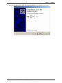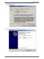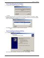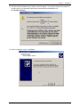
1
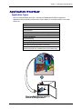
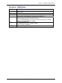
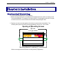
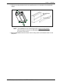
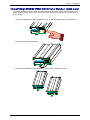
Chapter 1 – Description & Specifications MultiModem® GPRS External Wireless USB Modem Data/Fax/Voice MTCBA-G-UF1 MTCBA-G-UF2 User Guide Multi-Tech Systems, Inc. MultiModem® GPRS with USB User Guide 1 Chapter 1 – Description & Specifications User Guide for MultiModem® GPRS External Data/Fax/Voice USB Wireless Modem Models MTCBA-G-UF1 & MTCBA-G-UF2 P/N S000346E, Revision E Copyright © 2005 by Multi-Tech Systems, Inc. All rights reserved. This publication may not be reproduced, in whole or in part, without prior expressed written permission from Multi-Tech Systems, Inc. Multi-Tech Systems, Inc. makes no representation or warranties with respect to the contents hereof and specifically disclaims any implied warranties of merchantability or fitness for any particular purpose. Furthermore, Multi-Tech Systems, Inc. reserves the right to revise this publication and to make changes from time to time in the content hereof without obligation of Multi-Tech Systems, Inc., to notify any person or organization of such revisions or changes. Revision History Revision Date A 07/13/04 B 04/04/05 C 05/05/05 D 09/15/05 E 10/13/05 Description Initial Release Changed model nomenclature to GPRS. Revised installation procedures. Add WEEE update to User Guide. Change temperature range, added humidity rating, changed modem maintenance, and warranty chapter. Trademarks and Logos Multi-Tech, MultiModem and the Multi-Tech logo are trademarks of Multi-Tech Systems, Inc. Windows is a registered trademark of Microsoft in the U.S. and other countries. Other trademarks and trade names mentioned in this publication belong to their respective owners. Patents This device is covered by one or more of the following patents: 6,031,867; 6,012,113; 5,724,356; 5,673,268; 5,628,030; 5,450,425; 5,355,365. Other patents pending. World Headquarters Multi-Tech Systems, Inc. 2205 Woodale Drive, Mounds View, Minnesota 55112 (763) 785-3500; (800) 328-9717; Fax (763) 785-9874 Technical Support Country By Email By Phone France: India: U.K.: U.S. and Canada: Rest of the World: [email protected] [email protected] [email protected] [email protected] [email protected] (33) 1-64 61 09 81 91 (124) 6340778 (44) 118 959 7774 (800) 972-2439 (763) 717-5863 Internet Address: http://www.multitech.com Multi-Tech Systems, Inc. MultiModem® GPRS with USB User Guide 2 Chapter 1 – Description & Specifications Contents CHAPTER 1: PRODUCT DESCRIPTION AND SPECIFICATIONS .................................................................4 PRODUCT DESCRIPTION ..............................................................................................................................................4 Package Contents ...................................................................................................................................................4 Interfaces................................................................................................................................................................4 Parts to be Supplied by Wireless Service Provider ................................................................................................4 Parts to be Supplied by End User ..........................................................................................................................4 Antenna/RF Specifications .....................................................................................................................................5 AT Command Info ..................................................................................................................................................5 Phone Number for the Wireless Modem.................................................................................................................5 Network Access.......................................................................................................................................................5 Features..................................................................................................................................................................6 APPLICATION OVERVIEW ............................................................................................................................................7 Application Types ...................................................................................................................................................7 Benefits/Features in Applications...........................................................................................................................8 Functions – GSM Modes ........................................................................................................................................9 SPECIFICATIONS ........................................................................................................................................................10 General Specifications ......................................................................................................................................10 Electrical Characteristics ..................................................................................................................................10 Current Requirements ..........................................................................................................................................10 LED Indicators.....................................................................................................................................................11 CHAPTER 2: INSTALLATION..............................................................................................................................12 MECHANICAL MOUNTING .........................................................................................................................................12 INSERTING SIM/R-UIM CARD INTO HOLDER (GSM ONLY) ....................................................................................14 CONNECTING THE ANTENNA .....................................................................................................................................15 SOFTWARE INSTALLATION (WINDOWS XP/2000) .....................................................................................................16 Part A: Preparing the Setup.................................................................................................................................16 Part B: Installing the USB Driver ........................................................................................................................17 Part C: Associating PC Port with USB Driver ....................................................................................................21 Part D: Identifying the Port Number....................................................................................................................23 Part E: Installing the Modem INF File ................................................................................................................23 CONNECTING THE OPTIONAL HANDSET ....................................................................................................................28 MOBILE PHONETOOLS...............................................................................................................................................28 VERIFYING SIGNAL STRENGTH .................................................................................................................................28 VERIFYING NETWORK REGISTRATION ......................................................................................................................29 TESTING THE CONFIGURATION .................................................................................................................................30 UNINSTALLING THE MODEM SOFTWARE...................................................................................................................31 CHAPTER 3: TROUBLESHOOTING ...................................................................................................................33 TROUBLESHOOTING EXAMPLES ................................................................................................................................33 Situation A: The modem always returns «Error» when trying to issue a communication ...................................33 Situation B: The modem always returns «No carrier» when trying to issue a communication ...........................34 GSM/GPRS GENERAL FAQ.....................................................................................................................................35 GSM/GPRS FAQ ON THE IP STACK .........................................................................................................................37 FAQ FOR MOBILE PHONETOOLS V2.1 ......................................................................................................................38 CHAPTER 4: SAFETY ............................................................................................................................................39 SAFETY .....................................................................................................................................................................39 General Safety ......................................................................................................................................................39 Vehicle Safety .......................................................................................................................................................39 Maintenance of GPRS Modem .............................................................................................................................40 Your Responsibility...............................................................................................................................................40 CHAPTER 5: WARRANTY AND REPAIRS ........................................................................................................41 Replacement Parts................................................................................................................................................42 CHAPTER 6: REFERENCE INFORMATION .....................................................................................................43 WIRELESS MODEM REFERENCE INFORMATION .........................................................................................................43 APPENDIX A - WASTE ELECTRICAL AND ELECTRONIC EQUIPMENT (WEEE) STATEMENT .......44 Multi-Tech Systems, Inc. MultiModem® GPRS with USB User Guide 3 Chapter 1 – Description & Specifications Chapter 1: Product Description and Specifications Product Description The Multi-Tech MultiModem® GPRS is an external data/fax/voice wireless modem with an USB interface. It also supports mobile originated short message service (SMS) and mobile-terminated SMS. Designed for global use, it offers standards-based multi-band GSM/GPRS Class 10 performance. This ready-to-deploy, standalone modem allows developers to add wireless communication to products with a minimum of development time and expense. The MultiModem® GPRS is based on industry-standard open interfaces, is fully type approved, and can be desktop or panel mounted. Package Contents Basic Package one modem mounting bracket(s) one Quick Start Guide Bundled Package all Basic Package items, plus one USB cable (with Series A to Series B connectors) one antenna four adhesive-backed rubber feet for table-top mounting one product CD Interfaces The Wireless MultiModem has several interfaces: • • • • • LED function indicating operating status External antenna (via SMA connector) Serial and control link (via USB connector) Microphone and speaker (via handset jack) SIM card holder Parts to be Supplied by Wireless Service Provider • Subscriber Identity Module (SIM) configuration chip The SIM contains information specific to your wireless account and its features. Parts to be Supplied by End User • • mounting screws (screw shaft diameter = .17” max.) antenna In the bundled package, the Wireless MultiModem is shipped with an antenna suited for it. However, if the antenna supplied does not meet your application requirements (for size, shape, mounting style, etc.), you must supply an antenna yourself. In general, the antenna used must be both of the correct frequency and of a style appropriate to the application. See the Antenna/RF Specifications section below. Multi-Tech Systems, Inc. MultiModem® GPRS with USB User Guide 4 Chapter 1 – Description & Specifications Antenna/RF Specifications Frequency RX Frequency TX RF Power Stand Impedance VSWR Typical Radiated Gain Frequency RX Frequency TX RF Power Stand Impedance VSWR Typical Radiated Gain GSM 850 869 to 894 MHz 824 to 849 MHz 2W at 12.5% duty cycle 50 ohms <2 0 dBi on azimuth plane GSM 1800 1805 to 1880 MHz 1710 to 1785 MHz 1W at 12.5% duty cycle 50 ohms <2 0 dBi on azimuth plane GSM 1900 1930 to 1990 MHz 1850 to 1910 MHz 1W at 12.5% duty cycle AT Command Info AT commands for the GPRS wireless modem are published in a separate Reference Guide included on the product CD and posted on the Multi-Tech web site. IP commands for GPRS modems are also published in a separate Reference Guide included on the product CD and posted on the Multi-Tech web site. Phone Number for the Wireless Modem • Every wireless modem will have its own unique phone number. • The wireless modem’s phone number may simply be told to the subscriber or be on the SIM or both. Wireless provider implementations may vary. Network Access The network access arrangements to be specified in Windows Dial-Up Networking (of the computer that the wireless modem is serving) will vary according to the type of wireless service used. • For GSM-without-GPRS, a circuit-switched data connection is used. The user can set up DUN to make a conventional V.32 modem connection to any terminating modem at the other end. The phone number specified in DUN can be one supplied by the wireless service provider or another phone number related to a different dialup modem service (e.g., a dialup modem service phone number from any commercial or private dialup network). • For GSM-with-GPRS, a single DUN number is generally used by all of a wireless provider’s subscribers throughout its area of coverage (regional, nationwide, continental, etc.). Rather than being a literal phone directory number, as in conventional DUN, this is a code that gives the modem Internet access. Normally, this phone number is *99***1# . Multi-Tech Systems, Inc. MultiModem® GPRS with USB User Guide 5 Chapter 1 – Description & Specifications Features • GPRS Class 10 operation • Dual-band 850/1900 or 900/1800 GSM/GPRS • GSM Class 1 and Class 2 Group 3 FAX • Desktop or panel mounting • Short Message Services including text and PDU, point-to-point, cell broadcast • 14.4K GSM circuit switched data • SMA antenna connector and SIM socket • Serial interface supports DTE speeds to 115.2K • AT command compatible • MNP2 V.42bis data compression • Numerous LEDs provide operational status • ME + SIM phone book management • Fixed dialing number • SIM Toolkit Class 2 • SIM, network and service provider locks • Real time clock • Alarm management • UCS2 character set management • Packet data up to 85K bps • Embedded TCP/IP stack • Circuit-switched data (GSM) up to 14.4K bps transparent and nontransparent Multi-Tech Systems, Inc. MultiModem® GPRS with USB User Guide 6 Chapter 1 – Description & Specifications Application Overview Application Types With circuit switched data rates up to 14.4K bps, the MultiModem® GPRS is targeted at applications that periodically need to send or receive data over a wireless network. It is an ideal solution for: Appliances ATM Terminals Automotive Data Collection Gas Pumps Industrial and Medical Remote Monitoring Systems Remote Diagnostics Remote Metering Security Systems Vending/Gaming Machines Other devices requiring wireless connectivity. Note: The Wireless MultiModem must be mounted with at least 8 inches (20 cm) of clearance from the human body. RS232 Wireless MultiModem used in remote ATM application. Multi-Tech Systems, Inc. MultiModem® GPRS with USB User Guide 7 Chapter 1 – Description & Specifications Benefits/Features in Applications Short Development Time. The MultiModem® GPRS can make your existing and next generation device, machine, or system, communication-ready without requiring any hardware changes to its design. It actually provides faster time-to-market because it relieves the burden and expense of obtaining network and RF approvals. This complete, ready-to-deploy wireless modem allows you to enhance your product while you focus on developing its core features. Voice Features. The MultiModem® GPRS provides telephony and Dual Tone Multi Frequency (DTMF) functionality. It also allows for emergency calls as well as echo cancellation and noise reduction (option), and full rate, enhanced Full Rate and Half Rate (FR/EFR/HR). Short Message Services. The MultiModem® GPRS offers SMS features such as text and PDU, point-to-point (MT/MO) and cell broadcast. Compatible Supplementary Services. The MultiModem® GPRS is compatible with supplementary services such as call forwarding, call barring, multiparty, call waiting and call hold, calling line identification, advice of charge, USSD, closed user group and explicit call transfer. Management Features. The MultiModem® GPRS provides advanced management features including phone book management, fixed dialing number, and real time clock and alarm management. Industry-standard Modem Commands. The MultiModem® GPRS provides industry-standard ATstyle commands for ease of integration into your existing software application. Industrial Chassis. The MultiModem® GPRS is packaged in a rugged, water resistant, industrial chassis. The chassis has a USB connector for power and data. It has an SMA antenna connector. It also has modular phone handset receptacle. The chassis can be side-mounted on a panel or topmounted on a desktop or other surface. A set of LEDs indicates the modem’s operational status. Packet-Switched Data. The MultiModem® GPRS supports GPRS Class 10 packet-switched cellular data. This enables mobile Internet functionality by allowing interworking between the existing Internet and the cellular network at speeds up to 85K bps. Any service that is used over the fixed Internet today – File Transfer Protocol (FTP), web browsing, chat, e-mail, telnet -- is available over the cellular network, as well. The MultiModem GPRS supports PBCCH and coding schemes CS1 to CS4, and is compliant with SMG31bis. Circuit-Switched Data (CSD). The MultiModem® GPRS also supports GSM circuit-switched cellular data connections. Circuit-switched data connections support speeds up to 14.4K bps, Class 1 and Class 2 Group 3 fax, as well as MNP2 V.42bis compression. CSD cellular wireless connections are ideal for applications that require a quick wireless replacement of an existing pointto-point analog dial-up connection. They integrate seamlessly with your current application requiring little infrastructure change. Internet-Enabled. The MultiModem® GPRS includes an embedded TCP/IP protocol stack to bring Internet connectivity to any device. Using the embedded Internet protocols and the wirless connection to an IP network, it sends and receives data over the Internet. It can also serve a single web page in response to a web browser request. Multi-Tech Systems, Inc. MultiModem® GPRS with USB User Guide 8 Chapter 1 – Description & Specifications Functions – GSM Modes MODE Standard Interface SMS Data Fax GPRS DESCRIPTION Dual Band Extended GSM 900 MHz Class 4 (2W) and GSM 1800/1900 MHz Class 1 (1W) USB 12 Mbps. AT command set based on V.25ter and GSM 07.05 & 07.07 Mobile Originated (MO) and Mobile Terminated (MT) SMS Mode Text & PDU point to point. Cell broadcast in accordance with GSM 07.05. Asynchronous 2400, 4800, 9600 and 14400 bps. Data Transparent and Non Transparent modes. In Non Transparent Mode only: 300, 1200, 1200/75 baud rates are available. Mode 3.1 KHz (PSTN) and V110 (ISDN). 2400/4800/7200/9600 bps Fax GSM teleservice 62 in Transparent Mode. Class 2. Group 3 compatible. Class 10. Coding schemes: CS1 to CS4. Multi-Tech Systems, Inc. MultiModem® GPRS with USB User Guide 9 Chapter 1 – Description & Specifications Specifications General Specifications Mechanical Dimensions & Weight 4.3" w x 2.4" h x 0.94" d; 3.6 oz. (11 cm x 6.1 cm x 2.4 cm; 102 g) Antenna Connection type: SMA jack Data/Power Connector: USB Series A receptacle Connectors & Fasteners Phone Handset: Modular Handset Jack SIM receptacle: (standard) 0 to +50°C Relative humidity 20% to 90% noncondensing CE Mark EMC: FCC Part 2, 15, 22, 24, EN 55022 & EN 55024 Safety: UL 60950, EN 60950 Operating Temperatures Humidity Certifications Electrical Characteristics Switching the GSM modem on/off The device is permanently powered (when connected to the power supply). Voltage range : 5 to 32V DC GND : 0V Voltage Range Current Requirements GSM/GPRS 850/900 Typ. GSM/GPRS 1800/1900 Typ. Unit Input average supply current in comm. mode at Pmax 360 300 mA Input average supply current in idle mode 30 30 mA Parameters Multi-Tech Systems, Inc. MultiModem® GPRS with USB User Guide 10 Chapter 1 – Description & Specifications LED Indicators TD. RD. CD. LS. Transmit Data. Receive Data. Carrier Detect. Line Status. TR. Terminal Ready. PWR. Power. Lit when modem is transmitting data. Lit when modem is receiving data. Lit when data connection has been established. Continuous “on” state indicates that the wireless modem is not registered on the network. Flashing state indicates registration on network. Off state. Modem is off (not ready) or in download mode. Commonly called “Data Terminal Ready.” This is a readiness signal from the PC. Indicates presence of DC power when lit. Multi-Tech Systems, Inc. MultiModem® GPRS with USB User Guide 11 Chapter 2 – Installation Chapter 2: Installation Mechanical Mounting To mount the Wireless MultiModem, do the following: 1. Obtain mounting screws (two are needed) that are appropriate for the surface on which you will mount the MultiModem. For example, one might use two 6-32 self-tapping screws 5/8” in length to mount the unit in a truck to the wall of the cab behind the passenger’s seat. 2. Typically, the unit is mounted against a flat surface into which holes can be drilled. The mounting holes (center-to-center) must be separated by 125mm or 4 -15/16 inches. Spacing of Mounting Screws 125 mm or 4 1516 inches Mounting Bracket Locations (2) Drill the mounting holes at the desired mounting location (if applicable). Chapter 2 – Installation 3. Slide the mounting brackets into the corresponding slots on the backside of the MultiModem chassis. NOTE: Some MultiModem units will be shipped with a single mounting bracket. Slide it through the channel on the MultiModem chassis and secure it with screws. 4. Attach the MultiModem with two screws to the mounting surface at the desired location on the equipment. Multi-Tech Systems, Inc. MultiModem® GPRS with USB User Guide 13 Chapter 2 – Installation Inserting SIM/R-UIM Card into Holder (GSM Only) The wireless MultiModem requires a SIM card (Subscriber Identity Module) to operate on a GSM network. Some CDMA networks, mostly in China, require an R-UIM card (Removable User Identity Module). To install the card, do the following: 1. Using your fingernail or a small wedging tool (e.g., a small screwdriver), pry off the SIM cover. 2. Insert the SIM card into the holder. 3. Verify that the SIM card fits into the holder properly and then replace the cover. Multi-Tech Systems, Inc. MultiModem® GPRS with USB User Guide 14 Chapter 2 – Installation Connecting the Antenna Connect a suitable antenna to the SMA connector (see “Antenna/RF Specifications” in the User Guide). Antenna Connector (SMA Type) Multi-Tech Systems, Inc. MultiModem® GPRS with USB User Guide 15 Chapter 2 – Installation Software Installation (Windows XP/2000) There are five parts to this procedure: Part A: Preparing the Setup Part B: Installing the USB Driver Part C: Associating the PC Port with the USB Driver Part D: Identifying the Port Number Part E: Installing the Modem INF File Part A: Preparing the Setup 1. CAUTION! DO NOT connect the MultiModem to the PC at this point. Follow the steps below in sequence. Premature connection of the USB cable will cause the installation to fail. If you have already plugged in the USB cable prematurely, cancel out of the installation wizard and follow the instructions below. Insert the MultiModem Product CD into your CDROM drive. Insertion of the product CD will trigger the Autorun feature. At the MultiModem Autorun screen, click USB Installer. 2. After a brief delay (and one transient screen), the “MultiModem Setup -- Welcome” screen will appear. Click Next. Multi-Tech Systems, Inc. MultiModem® GPRS with USB User Guide 16 Chapter 2 – Installation Part B: Installing the USB Driver 3. After a brief transient progress screen, the Choose the Options screen will appear. Select Install MultiTech Wireless USB Modem and click Next. 4. A ‘Windows Logo Testing’ screen will appear. Click Continue Anyway. 5. Transient screens will appear while files are being copied. Multi-Tech Systems, Inc. MultiModem® GPRS with USB User Guide 17 Chapter 2 – Installation 6. CAUTION! Do not click OK at this screen until the stated conditions have been met. Clicking OK prematurely will cause the installation to fail. Connect the USB cable between the MultiModem and the computer. Wait while Windows prepares the installation. The screen above will stay open behind other screens. You will need to access it later (see step 17). Here begins the first of two installation sequences, the first for the USB driver, the second for the port. A New Hardware Found bubble will emerge from the tray area (lower right corner) of the screen and appear briefly. 7. The Welcome to the Found New Hardware Wizard screen will appear. This is the beginning of the “Found New Hardware” sequence for the USB driver. Select “No, not this time” and click Next. Multi-Tech Systems, Inc. MultiModem® GPRS with USB User Guide 18 Chapter 2 – Installation 8. The next screen says “This wizard helps you install software for:” and then names the USB driver by type. Select “Install the software automatically” and then click Next. 9. A transient screen appears while files are being copied. 10. A second ‘Windows Logo Testing’ screen will appear. This screen pertains to the USB driver. Click Continue Anyway. Multi-Tech Systems, Inc. MultiModem® GPRS with USB User Guide 19 Chapter 2 – Installation 11. When the Completing the Found New Hardware Wizard screen appears, click “Finish.” Multi-Tech Systems, Inc. MultiModem® GPRS with USB User Guide 20 Chapter 2 – Installation Part C: Associating PC Port with USB Driver 12. Wait while Windows prepares the next phase of the installation (associating the PC port with the USB drive). A New Hardware Found bubble will emerge from the tray area (lower right corner) of the screen and appear briefly. 13. The Welcome to the Found New Hardware Wizard screen will appear. This is the beginning of the “Found New Hardware” sequence for the port. Select “No, not this time” and click Next. 14. The next screen says “This wizard helps you install software for:” and then names the serial port by type. Select “Install the software automatically” and then click Next. Multi-Tech Systems, Inc. MultiModem® GPRS with USB User Guide 21 Chapter 2 – Installation 15. A third ‘Windows Logo Testing’ screen will appear. This screen pertains to the serial port. Click Continue Anyway. 16. When the Completing the Found New Hardware Wizard screen appears, click “Finish.” Multi-Tech Systems, Inc. MultiModem® GPRS with USB User Guide 22 Chapter 2 – Installation Part D: Identifying the Port Number 17. Go back to the “Connect the USB Modem …” screen. Click OK. 18. Wait while Windows prepares the next phase of the installation (installation of the modem). A New Hardware Found bubble will emerge from the tray area (lower right corner) of the screen and appear briefly. Then the Detected USB Device screen will appear. Click Install. Note the COM port number that has been assigned. COM____ Part E: Installing the Modem INF File 19. The Install New Modem screen will appear. Select “Don’t detect my modem; I will select it from a list.” Then click Next. Multi-Tech Systems, Inc. MultiModem® GPRS with USB User Guide 23 Chapter 2 – Installation 20. In the “Models” list of the Install New Modem screen, select your modem (a MultiTech Systems Wireless Modem of type CDMA USB, or GSM/GPRS USB). Then click Next. 21. At the next screen, you must select the port on which you will install the modem. The COM port number here should be the same as that shown in step 18 above. Click Next. Multi-Tech Systems, Inc. MultiModem® GPRS with USB User Guide 24 Chapter 2 – Installation 22. A fourth and final ‘Windows Logo Testing’ screen will appear. This screen pertains to the creation of a modem entity in the operating system that accommodates the MultiModem unit. Click Continue Anyway. 23. At the ‘Completion’ screen, click Finish. Multi-Tech Systems, Inc. MultiModem® GPRS with USB User Guide 25 Chapter 2 – Installation 24. The presence of a modem in the computer can now be seen in the Modems Properties screen. Click OK to exit from the Modems Properties screen. 25. The ‘Successful Installation’ screen will appear. Multi-Tech Systems, Inc. MultiModem® GPRS with USB User Guide 26 Chapter 2 – Installation 26. A final ‘Completion’ screen will appear. Click Finish. Multi-Tech Systems, Inc. MultiModem® GPRS with USB User Guide 27 Chapter 2 – Installation Connecting the Optional Handset If you intend to use a phone handset, connect it to the MultiModem now. Modular Handset Cable (use of handset optional; handset cable not included) Mobile Phonetools For initial configuration of your wireless device, Multi-Tech offers a Windows® based mobile Phone Tools application. To load mobile Phone Tools, click on the mobile Phone Tools icon on your product CD and follow the on-screen prompts. Verifying Signal Strength The Wireless MultiModem establishes a call if the signal is sufficiently strong. To verify the signal strength, do the following: 1. Using the HyperTerminal program at the computer to which the Wireless MultiModem is connected, type the AT command AT+CSQ. A value for the received signal strength will be returned. 2. Verify the result with the following chart: Signal Strength Verification Value of signal strength Signal strength (AT+CSQ response) (RSSI) 10 - 31 Sufficient 0-9 Weak or Insufficient 99 Insufficient Multi-Tech Systems, Inc. MultiModem® GPRS with USB User Guide 28 Chapter 2 – Installation Verifying Network Registration In this procedure, you will verify that the Wireless MultiModem has been registered on the wireless network. To do so, you will use the common communications program Hyperterminal. 1. Using the Hyperterminal program at the computer to which the Wireless MultiModem is connected, type the AT command AT+CREG?. A value for the modem’s network registration status will be returned. 2. Verify the result with the following chart: Network Registration Verification Value Network Registration Status 0, 1 Yes 0, 5 Yes (registered roaming) Note: If the modem is not registered, perform the procedure for verifying signal strength to determine the strength of the received signal. Multi-Tech Systems, Inc. MultiModem® GPRS with USB User Guide 29 Chapter 2 – Installation Testing the Configuration Description AT Commands Response Returned Comments AT+CPIN =1234 OK PIN Code accepted +CME ERROR : 16 +CME ERROR : 3 Incorrect PIN Code PIN already entered (with +CMEE : 1 mode) modem synchronized on the network synchronization lost, re-synchronization attempt Modem not synchronized on network. No synchronization attempt Enter PIN Code AT + CREG ? Module synchro checking Receiving an incoming call CREG = <mode>, 1 CREG = <mode>, 2 CREG = <mode>, 0 RING ATA Answer the call. OK ATD1234; Initiate a call OK CME ERROR :11 CME ERROR :3 Initiate an emergency call Communication loss Hang up ATD112; OK Don’t forget the “;” at the end for “voice” calls. Communication established PIN Code not entered (with +CMEE : 1 mode) AOC credit (Advice of Charge tells the user how much a call will cost) has been exceeded or a communication is already established. Don’t forget the “;” at the end for “voice” calls. NO CARRIER ATH OK Store the parameters in non-volatile memory AT&W OK The communications program has saved the configuration settings in nonvolatile memory. Multi-Tech Systems, Inc. MultiModem® GPRS with USB User Guide 30 Chapter 2 – Installation Uninstalling the Modem Software 1. Insert the product CD into the CD-ROM drive. The Autorun function will bring up the main menu screen. Click on USB Installer. 2. A transient screen will appear briefly. At the ‘Welcome’ screen, click Next. Multi-Tech Systems, Inc. MultiModem® GPRS with USB User Guide 31 Chapter 2 – Installation 3. A transient screen will appear briefly. At the Choose the options screen, select “Uninstall MultiTech Wireless USB Modem” and click Next. 4. A transient screen will appear briefly while files are being deleted and while the registry is being updated. At the ‘Completion’ screen, click Finish. Multi-Tech Systems, Inc. MultiModem® GPRS with USB User Guide 32 Chapter 3 – Troubleshooting Chapter 3: Troubleshooting Troubleshooting Examples Situation A: The modem always returns «Error» when trying to issue a communication If the Wireless MultiModem returns a message of error upon an attempted transmission of data or voice signals, see the table below for possible causes and solutions. Solutions for “error” message situations If the modem returns Then ask … Action Error Is the modem registered on the network? Follow “Verifying network registration" procedure to be sure modem is registered on network. Is the modem receiving an incoming call or is it already in communication? End any communication using the ATH command. Does AT+CREG? return 0,1 (registered) or 0,5 (registered roaming)? If not, check for adequate signal strength on network. Use AT+CSQ. Is the selected bearer type supported by the called party? In comm. program, type AT+CMEE=1 to view the extended error codes (see “Error Results Codes" in the AT Command guide). Be sure called party and network support selected bearer type. Be sure that semi-colon (“;”) is typed immediately after the phone number in the AT command. e.g., ATD######; See “Verifying Signal Strength.” Is the selected bearer type supported by the network? Is the received signal strong enough? Is the antenna properly connected? See “Antenna/RF Specifications.” Multi-Tech Systems, Inc. MultiModem® GPRS with USB User Guide 33 Chapter 3 – Troubleshooting Situation B: The modem always returns «No carrier» when trying to issue a communication Solutions for “no carrier” message If the modem returns … Then ask … no carrier (esp. for data communication) Is the selected bearer type supported by the called party? Is the selected bearer type supported by the network? no carrier (esp. for voice communication) Is the received signal strong enough? Is the antenna properly connected? Action Type AT+CEER to view the extended error code (see “Error Results Codes" in the AT Command guide). Be sure that the selected bearer type is supported by the called party. Be sure that the selected bearer type is supported by the network. If no success, try bearer selection type: AT+CBST=0,0,3 Be sure SIM card is available for data/fax calls. Be sure that the semicolon character (“;”) is typed immediately after the phone number in the AT command. E.g., ATD######; type AT+CBST=0,0,3 Configure the SIM card for data/fax calls. See “Verifying Signal Strength.” See “Antenna/RF Specifications.” Multi-Tech Systems, Inc. MultiModem® GPRS with USB User Guide 34 Chapter 3 – Troubleshooting GSM/GPRS General FAQ The modem is answering, but seems not to be doing anything. What’s the problem? • • The modem is answering in voice mode. If you are trying to make a data call, make sure the account has CSD service. You will also need the data number (separate number from the main phone number given by the provider). I am trying to make a data connection by dialing from my wireless modem to an analog modem. Why does the analog modem answer and send tones, but never connect? • • To make a data call you must use the ATD<number> command. Make sure the account has CSD service. How do I get the voice portion to work so I can talk to others using the wireless modem? • • You will need a cable that has the speaker pins connected to a speaker and mic. MTS offers a “Y” cable that splits out to an RJ10 connector. The RJ10 connector plugs into the receiver of a handset. How do I make a GPRS (Internet) connection using Windows? • • • You must set the APN into the modem by using the command: AT+CGDCONT=1,”IP”,”<APN>” (APN is given by the provider). This must be done using a terminal program. Create a dial-up connection in Windows to dial the number ‘*99***1#’ using no username or password. You can also use Mobile PhoneTools which will set the APN automatically and create a dial connection. How do I make an Internet connection to my dial-up ISP? • • Make sure you have CSD service. Create a dial-up connection to the ISP’s access number. Then, using your account username and password, choose the wireless modem as the device. How does faxing work? • • You will need fax services set up on your account. You should receive a separate phone number for fax, just as you have done for voice and data. You must call the fax number for the modem to receive a fax. You will also need a fax software package (not provided by MTS). Why do I get garbage when I am in HyperTerminal and I try to connect to the GPRS network by sending ‘ATD*99***1#’? I have already set the APN correctly. • HyperTerminal will only return garbage in this situation. You will need to use a PPP application instead. The PPP application is needed to control the PPP session. When I do ‘ATD*99***1#’ in HyperTerminal I get an error. • • • • Set AT+CMEE=1 and then try again to see what CME error is shown. Check the CME error in the AT Command Reference Guide. Make sure the APN is programmed correctly into the modem by sending ‘AT+CGDCONT?’. Check ‘AT+CGCLASS?’, If it returns anything other than “B”, change it to “B” by setting ‘AT+CGCLASS=”B”’. Make sure that you have GPRS (packet switched data) service. I can’t make any outoing calls and I have a solid LS light. I’m receiving a NO CARRIER response. • • • Make sure the antenna is connected and the SIM is inserted correctly. Check signal and registration: ‘AT+CSQ’ (10-31 is good), ‘AT+CREG?’ (0,1 is registered & 0,5 is roaming). Check NO CARRIER issue with ‘AT+CEER’. Look up error code in AT Command Reference Guide. Multi-Tech Systems, Inc. MultiModem® GPRS with USB User Guide 35 Chapter 3 – Troubleshooting The modem will not answer. • • • To have modem auto-answer, set modem with ‘ATS0=1’. Use ‘AT&W’ to store the setting. Send ‘ATA’ to the modem once the RING is indicated on the terminal screen. If you aren’t providing DTR, you may need to set the modem to ignore DTR by using this command: ‘AT&D0’ . Which providers can I use? • • T-Mobile, AT&T, and Cingular AT&T doesn’t support CSD (wireless to analog connection) I am trying to make a GPRS connection using a Windows dial-up session. It connects and then immediately disconnects. What’s wrong? • • • Make sure the APN is stored in the modem (the APN is given by the provider). Check the APN with ‘AT+CGDCONT?’ to make sure it is correct. If no APN is inserted, then insert the correct APN: ‘AT+CGDCONT=1,”IP”,”<APN>”’. When I try to make a GPRS connection using Windows dial-up I get this error: “Hardware Failure”. • • • Check the modem to make sure it is installed. Check the Modem Properties screen to be sure the modem can be queried. Make sure the modem is not being held by another application. Look for the TR light indication. If it is on, most likely another application is holding onto the port. Try rebooting the system. What is the maximum number of characters I can use to send a SMS message? • • The modem supports up to 160 characters max. In PDU mode using 7-bit, the modem still supports 160 characters. But in 8-bit mode the modem will only support 70 characters. Multi-Tech Systems, Inc. MultiModem® GPRS with USB User Guide 36 Chapter 3 – Troubleshooting GSM/GPRS FAQ on the IP Stack Whenever I send the # commands, I receive an error. • • • You must enable the stack before the modem will accept the # commands. ‘AT+WOPEN=1’ will enable the stack and ‘AT#VVERSION’ will display the version of the stack. If you receive an error when sending ‘AT+WOPEN=1’, then you may not have the stack present on the modem. How do I know if I have the stack? • Use the ‘AT+WOPEN=1’ command. If it returns an error, then the stack may not be present in the modem. How do I make a GPRS connection using the stack? • Send: AT#GPRSMODE=1 (sets the modem to GPRS mode) AT#APNSERV=”APN” (sets the APN for the modem to connect) AT+CGATT=1 (attaches the modem to the GPRS network) AT+CGREG=1 (registers the modem onto the GPRS network) AT#CONNECTIONSTART (to start the connection) AT#CONNECTIONSTOP (to stop the connection) I have T-Mobile. When I try to establish a GPRS connection using the stack, the modem doesn’t connect. It seems like the modem gets reset. • • • Check the firmware version: ‘AT+CGMR’. Version 640b had a bug that caused the modem to reset when using a non-authenticated account. Authenticated accounts such as AT&T and Cingular work OK. Firmware version 641a fixes this issue. You will have to send the modem in for a firmware upgrade. Send it to the attention of the MultiTech Repairs Department. Include a letter stating the problem and that you need the version 641a firmware. How do I make a connection to my ISP using the stack? Make sure you have CSD service. Send: AT#GPRSMODE=0 (sets the modem to GSM mode) AT#DIALN1=”ISP’s access #” AT#DIALSELECT=1 AT#ISPUN=”username” AT#ISPPW=”password” AT#CONNECTIONSTART AT#CONNECTIONSTOP I can’t use the stack to connect to the GPRS network. I keep getting CME errors. • • • Check the CME error number in the AT Command Reference Guide. Make sure the modem is attached and registered with the ‘AT+CGATT?’ and ‘AT+CGREG?’ commands. Make sure the APN is correct with ‘AT#APNSERV?’. Can I ping the modem when I have a connection established with the stack? • Yes, but you must be connected to an APN or server that provides public IP address and is not blocked by a firewall. Can I ping out using the stack? • • • • Yes, but you must have the firmware version 641a or higher. The command is ‘AT#PINGREMOTE=”<address to ping>”’ and ‘AT#PING’ to start the ping. You must have a connection established with the stack in order to use the ping commands. Does the stack support UDP? • Yes, but only on the firmware version 641a and above. Multi-Tech Systems, Inc. MultiModem® GPRS with USB User Guide 37 Chapter 3 – Troubleshooting FAQ for Mobile PhoneTools v2.1 What is the Mobile PhoneTools program? • A software developed by BVRP used for the GPRS & CDMA modems for voice, SMS, email, and Internet (packet-switched) connections. How do I make an Internet connection? • Click on Menu – Setup – Internet Connection; or click on the globe icon that says “Create Internet Connection”. Then follow the wizard. How do I send a SMS message? • Click on Menu – Send – Send Short Message; or click on the envelope icon that says “Send Message”. How do I make a voice call? • • Dial the phone number using the numeric pad on the keyboard, or click on the keypad using the mouse. Then click on the “YES” button to initiate the call. You must use our “Y” cable or your own voice-pinned cable to be able to talk. Multi-Tech Systems, Inc. MultiModem® GPRS with USB User Guide 38 Chapter 4 – Safety Chapter 4: Safety Safety General Safety The modem is designed for and intended to be used in fixed and mobile applications. “Fixed” means that the device is physically secured at one location and is not able to be easily moved to another location. “Mobile” means that the device is designed to be used in other than fixed locations and generally in such a way that a separation distance of at least 20 cm (8 inches) is normally maintained between the transmitter’s antenna and the body of the user or nearby persons. The Modem is not designed for or intended to be used in portable applications (within 20 cm. or 8 in. of the body of the user) and such uses are strictly prohibited. It is important to follow any special regulations regarding the use of radio equipment due in particular to the possibility of radio frequency, RF, interference. Please follow the safety advice given below carefully. • Power OFF your Wireless MultiModem when in an aircraft. The use of cellular telephones in an aircraft may endanger the operation of the aircraft, disrupt the cellular network and is illegal. Failure to observe this instruction may lead to suspension or denial of cellular telephone services to the offender, or legal action or both. • Power OFF your Wireless MultiModem when around gasoline or diesel-fuel pumps and before filling your vehicle with fuel. • Power OFF your Wireless MultiModem in hospitals and any other place where medical equipment may be in use. • Respect restrictions on the use of radio equipment in fuel depots, chemical plants or where blasting operations are in progress. • There may be a hazard associated with the operation of your Wireless MultiModem close to inadequately protected personal medical devices such as hearing aids and pacemakers. Consult the manufacturers of the medical device to determine if it is adequately protected. • Operation of your Wireless MultiModem close to other electronic equipment may also cause interference if the equipment is inadequately protected. Observe any warning signs and manufacturers’ recommendations. Vehicle Safety • Respect national regulations on the use of cellular telephones in vehicles. Road safety always comes first. • If incorrectly installed in a vehicle, the operation of Wireless MultiModem telephone could interfere with the correct functioning of vehicle electronics. To avoid such problems, be sure that qualified personnel have performed the installation. Verification of the protection of vehicle electronics should be part of the installation. • The use of an alert device to operate a vehicle’s lights or horn on public roads is not permitted. Multi-Tech Systems, Inc. MultiModem® GPRS with USB User Guide 39 Chapter 4 – Safety Maintenance of GPRS Modem • Your Wireless MultiModem is the product of advanced engineering, design and craftsmanship and should be treated with care. The suggestions below will help you to enjoy this product for many years. Do not expose the Wireless MultiModem to any extreme environment where the temperature is above 50ºC or humidity is above 90% noncondensing. • Do not attempt to disassemble the Wireless MultiModem. There are no user serviceable parts inside. • Do not expose the Wireless MultiModem to water, rain or spilled beverages. It is not waterproof. • Do not place the Wireless MultiModem alongside computer discs, credit or travel cards, or other magnetic media. The phone may affect the information contained on discs or cards. • The use of accessories not authorized by Multi-Tech or not compliant with Multi-Tech's accessory specifications may invalidate the warranty of the Wireless MultiModem. • In the unlikely event of a fault in the Wireless MultiModem, contact Multi-Tech Tech Support. Your Responsibility This Wireless MultiModem is your responsibility. Please treat it with care respecting all local regulations. It is not a toy. Therefore, keep it in a safe place at all times and out of the reach of children. Try to remember your Unlock and PIN codes. Become familiar with and use the security features to block unauthorized use and theft. Multi-Tech Systems, Inc. MultiModem® GPRS with USB User Guide 40 Chapter 5 – Warranty and Repairs Chapter 5: Warranty and Repairs Multi_Tech Warranty Statement Multi-Tech Systems, Inc., (hereafter “MTS”) warrants that its products will be free from defects in material or workmanship for a period of two, five, or ten years (depending on model) from date of purchase, or if proof of purchase is not provided, two, five, or ten years (depending on model) from date of shipment. MTS MAKES NO OTHER WARRANTY, EXPRESS OR IMPLIED, AND ALL IMPLIED WARRANTIES OF MERCHANTABILITY AND FITNESS FOR A PARTICULAR PURPOSE ARE HEREBY DISCLAIMED. This warranty does not apply to any products which have been damaged by lightning storms, water, or power surges or which have been neglected, altered, abused, used for a purpose other than the one for which they were manufactured, repaired by Customer or any party without MTS’s written authorization, or used in any manner inconsistent with MTS’s instructions. MTS’s entire obligation under this warranty shall be limited (at MTS’s option) to repair or replacement of any products which prove to be defective within the warranty period or, at MTS’s option, issuance of a refund of the purchase price. Defective products must be returned by Customer to MTS’s factory — transportation prepaid. MTS WILL NOT BE LIABLE FOR CONSEQUENTIAL DAMAGES, AND UNDER NO CIRCUMSTANCES WILL ITS LIABILITY EXCEED THE PRICE FOR DEFECTIVE PRODUCTS. Repair Procedures for U.S. and Canadian Customers In the event that service is required, products may be shipped, freight prepaid, to our Mounds View, Minnesota factory: Multi-Tech Systems, Inc. 2205 Woodale Drive Mounds View, MN 55112 U.S.A Attn: Repairs, Serial # ____________ A Returned Materials Authorization (RMA) is not required. Return shipping charges (surface) will be paid by MTS to destinations in U.S. and Canada. Please include, inside the shipping box, a description of the problem, a return shipping address (must have street address, not P.O. Box), your telephone number, and if the product is out of warranty, a check or purchase order for repair charges. For out of warranty repair charges, go to COMPANY/Policies/warranty/ Extended two-year overnight replacement service agreements are available for selected products. Please call MTS customer service at (888) 288-5470 or visit our web site at COMPANY/Programs/overnight_replacement for details on rates and coverage’s. Please direct your questions regarding technical matters, product configuration, verification that the product is defective, etc., to our Technical Support department at (800) 972-2439 or email [email protected]. Please direct your questions regarding repair expediting, receiving, shipping, billing, etc., to our Repair Accounting department at (800) 328-9717 or (763) 717-5631, or email [email protected]. Repairs for damages caused by lightning storms, water, power surges, incorrect installation, physical abuse, or usercaused damages are billed on a time-plus-materials basis. Multi-Tech Systems, Inc. MultiModem® GPRS with USB User Guide 41 Chapter 5 – Warranty and Repairs Repair Procedures for International Customers (Outside U.S.A. and Canada) Your original point of purchase Reseller may offer the quickest and most economical repair option for your Multi-Tech product. You may also contact any Multi-Tech sales office for information about the nearest distributor or other repair service for your Multi-Tech product. The Multi-Tech sales office directory is available at http://www.multitech.com/COMPANY/contact_us/ In the event that factory service is required, products may be shipped, freight prepaid to our Mounds View, Minnesota factory. Recommended international shipment methods are via Federal Express, UPS or DHL courier services, or by airmail parcel post; shipments made by any other method will be refused. Please include, inside the shipping box, a description of the problem, a return shipping address (must have street address, not P.O. Box), your telephone number, and if the product is out of warranty, a check in U.S. dollars drawn on a U.S. bank or your company’s purchase order for repair charges. Repaired units shall be shipped freight collect, unless other arrangements are made in advance. Please direct your questions regarding technical matters, product configuration, verification that the product is defective, etc., to our Technical Support department nearest you or email [email protected]. When calling the U.S., please direct your questions regarding repair expediting, receiving, shipping, billing, etc., to our Repair Accounting department at +(763) 717-5631 in the U.S.A., or email [email protected]. Repairs for damages caused by lightning storms, water, power surges, incorrect installation, physical abuse, or usercaused damages are billed on a time-plus-materials basis. Repair Procedures for International Distributors International distributors should contact their MTS International sales representative for information about the repair of the Multi-Tech products. Please direct your questions regarding technical matters, product configuration, verification that the product is defective, etc., to our International Technical Support department at +(763)717-5863. When calling the U.S., please direct your questions regarding repair expediting, receiving, shipping, billing, etc., to our Repair Accounting department at +(763) 717-5631 in the U.S.A. or email [email protected]. Repairs for damages caused by lightning storms, water, power surges, incorrect installation, physical abuse, or usercaused damages are billed on a time-plus-materials basis Replacement Parts SupplyNet, Inc., can supply you with replacement power supplies, cables and connectors for selected Multi-Tech products. You can place an order with SupplyNet via mail, phone, fax or the Internet at the following addresses: Mail: SupplyNet, Inc. 614 Corporate Way Valley Cottage, NY 10989 Phone: 800 826-0279 Fax: 914 267-2420 Email: Internet: [email protected] http://www.thesupplynet.com Multi-Tech Systems, Inc. MultiModem® GPRS with USB User Guide 42 Chapter 6 – Reference Information Chapter 6: Reference Information Wireless Modem Reference Information GSM reference documents: GSM 03.40, GSM 03.45, GSM 04.11,GSM 04.21, GSM05.08, GSM 07.01,GSM 07.02, GSM 07.05, GSM 07.07. ETSI contact: Service: ETSI Secretariat F-06921 Sophia Antipolis Cedex, France e-mail: [email protected] The AT commands manual is available on the Multi-Tech web site: http://www.multitech.com Disclaimer Wireless MultiModem specifications and manuals are subject to change without notice. MTS assumes no liability for damage incurred directly or indirectly from errors, omissions or discrepancies between the Wireless MultiModem and its manual. Multi-Tech Systems, Inc. MultiModem® GPRS with USB User Guide 43 Appendix A – WEEE Statement Appendix A - Waste Electrical and Electronic Equipment (WEEE) Statement July, 2005 The WEEE directive places an obligation on EU-based manufacturers, distributors, retailers and importers to take-back electronics products at the end of their useful life. A sister Directive, ROHS (Restriction of Hazardous Substances) complements the WEEE Directive by banning the presence of specific hazardous substances in the products at the design phase. The WEEE Directive covers all Multi-Tech products imported into the EU as of August 13, 2005. EU-based manufacturers, distributors, retailers and importers are obliged to finance the costs of recovery from municipal collection points, reuse, and recycling of specified percentages per the WEEE requirements. Instructions for Disposal of WEEE by Users in the European Union The symbol shown below is on the product or on its packaging, which indicates that this product must not be disposed of with other waste. Instead, it is the user’s responsibility to dispose of their waste equipment by handing it over to a designated collection point for the recycling of waste electrical and electronic equipment. The separate collection and recycling of your waste equipment at the time of disposal will help to conserve natural resources and ensure that it is recycled in a manner that protects human health and the environment. For more information about where you can drop off your waste equipment for recycling, please contact your local city office, your household waste disposal service or where you purchased the product. Multi-Tech Systems, Inc. MultiModem® GPRS with USB User Guide 44