1
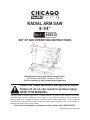
RADIAL ARM SAW
8-1/4”
42933
Set up and Operating Instructions
Distributed exclusively by Harbor Freight Tools®.
3491 Mission Oaks Blvd., Camarillo, CA 93011
Visit our website at: http://www.harborfreight.com
Read this material before using this product.
Failure to do so can result in serious injury.
Save this manual.
Copyright© 2000 by Harbor Freight Tools®. All rights reserved. No portion of this manual or any artwork
contained herein may be reproduced in any shape or form without the express written consent of
Harbor Freight Tools. Diagrams within this manual may not be drawn proportionally. Due to continuing
improvements, actual product may differ slightly from the product described herein. Tools required for
assembly and service may not be included.
For technical questions or replacement parts, please call 1-800-444-3353.
REV 04k; 06l; manual revised 09d
Contents
Important SAFETY
Information............................ 3
General Tool Safety
Warnings...................................... 3
Grounding Instructions..... 5
Operation................................ 16
Cross Cutting............................ 16
Mitre Cross Cutting................ 16
Bevel Cross Cutting............... 17
Compound Cross Cutting...... 17
In-Rip Cutting.............................. 17
Out-Rip Cutting........................... 18
110-120 V~ Grounded Tools:
Tools with Three Prong
Plugs............................................. 5
Maintenance........................... 19
Radial Arm Saw Safety
Warnings...................................... 5
Parts List................................. 21
Troubleshooting...................... 20
Essential Straight Pushstick Features and
Functions.................................... 7
Assembly Diagram (1-97)..... 22
Specifications........................ 10
LIMITED 90 DAY WARRANTY.... 24
Assembly Diagram (98-167). 23
Unpacking................................ 10
Installation............................ 10
Operating Controls........... 12
Adjustments........................... 14
Cutting Kerf Marks............. 15
SKU 42933
For technical questions, please call 1-800-444-3353.
Page 2
NOTICE is used to
address practices
not related to personal injury.
Save This Manual
Keep this manual for the safety warnings and precautions, assembly, operating, inspection, maintenance and cleaning
procedures. Write the product’s serial
number in the back of the manual near the
assembly diagram (or month and year of
purchase if product has no number). Keep
this manual and the receipt in a safe and
dry place for future reference.
CAUTION, without
the safety alert
symbol, is used to address
practices not related to
personal injury.
General Tool Safety Warnings
WARNING Read all safety
warnings and instructions.
Failure to follow the warnings and
instructions may result in electric
shock, fire and/or serious injury.
Save all warnings and
instructions for future reference.
Important SAFETY
Information
In this manual, on the labeling,
and all other information provided with this product:
This is the safety alert
symbol. It is used to alert
you to potential personal
injury hazards. Obey all
safety messages that
follow this symbol to avoid
possible injury or death.
DANGER indicates
a hazardous
situation which, if not
avoided, will result in death or
serious injury.
1.
KEEP GUARDS IN PLACE and in
working order.
2.
REMOVE ADJUSTING KEYS AND
WRENCHES. Form habit of checking to see that keys and adjusting
wrenches are removed from tool
before turning it on.
3.
KEEP WORK AREA CLEAN. Cluttered areas and benches invite accidents.
4.
DON’T USE IN DANGEROUS ENVIRONMENT. Don’t use power tools
in damp or wet locations, or expose
them to rain. Keep work area well
lighted.
5.
KEEP CHILDREN AWAY. All visitors
should be kept safe distance from
work area.
6.
MAKE WORKSHOP KID PROOF
with padlocks, master switches, or by
removing starter keys.
7.
DON’T FORCE TOOL. It will do the
job better and safer at the rate for
which it was designed.
WARNING
indicates a
hazardous situation which, if
not avoided, could result in
death or serious injury.
CAUTION, used
with the safety
alert symbol, indicates a
hazardous situation which, if
not avoided, could result in
minor or moderate injury.
SKU 42933
For technical questions, please call 1-800-444-3353.
Page 3
8.
USE RIGHT TOOL. Don’t force tool
or attachment to do a job for which it
was not designed.
RECOMMENDED MINIMUM WIRE
GAUGE FOR EXTENSION CORDS
(120 VOLT)
NAMEPLATE
AMPERES
(at full load)
EXTENSION CORD
LENGTH
25’
50’ 100’ 150’
0–6
18
16
16
14
6.1 – 10
18
16
14
12
10.1 – 12
16
16
14
12
12.1 – 16
14
12
Do not use.
TABLE A
9.
USE PROPER EXTENSION CORD.
Make sure your extension cord is
in good condition. When using an
extension cord, be sure to use one
heavy enough to carry the current
your product will draw. An undersized
cord will cause a drop in line voltage
resulting in loss of power and overheating. Table A shows the correct
size to use depending on cord length
and nameplate ampere rating. If in
doubt, use the next heavier gauge.
The smaller the gauge number, the
heavier the cord.
10. WEAR PROPER APPAREL. Do not
wear loose clothing, gloves, neckties, rings, bracelets, or other jewelry
which may get caught in moving
parts. Nonslip footwear is recommended. Wear protective hair covering to contain long hair.
11. ALWAYS USE SAFETY GLASSES.
Also use face or dust mask if cutting
operation is dusty. Everyday eyeglasses only have impact resistant
lenses, they are NOT safety glasses.
12. SECURE WORK. Use clamps or a
vise to hold work when practical. It’s
SKU 42933
safer than using your hand and it
frees both hands to operate tool.
13. DON’T OVERREACH. Keep proper
footing and balance at all times.
14. MAINTAIN TOOLS WITH CARE.
Keep tools sharp and clean for best
and safest performance. Follow
instructions for lubricating and changing accessories.
15. DISCONNECT TOOLS before servicing; when changing accessories,
such as blades, bits, cutters, and the
like.
16. REDUCE THE RISK OF UNINTENTIONAL STARTING. Make sure
switch is in off position before plugging in.
17. USE RECOMMENDED ACCESSORIES. Consult the owner’s manual for
recommended accessories. The use
of improper accessories may cause
risk of injury to persons.
18. NEVER STAND ON TOOL. Serious
injury could occur if the tool is tipped
or if the cutting tool is unintentionally
contacted.
19. CHECK DAMAGED PARTS. Before
further use of the tool, a guard or
other part that is damaged should
be carefully checked to determine
that it will operate properly and perform its intended function – check for
alignment of moving parts, binding
of moving parts, breakage of parts,
mounting, and any other conditions
that may affect its operation. A guard
or other part that is damaged should
be properly repaired or replaced.
20. DIRECTION OF FEED. Feed work
into a blade or cutter against the
direction of rotation of the blade or
cutter only.
For technical questions, please call 1-800-444-3353.
Page 4
21. NEVER LEAVE TOOL RUNNING
UNATTENDED. TURN POWER OFF.
Don’t leave tool until it comes to a
complete stop.
4.
Check with a qualified electrician or
service personnel if the grounding
instructions are not completely understood, or if in doubt as to whether the
tool is properly grounded.
Grounding Instructions
5.
Use only 3-wire extension cords that
have 3-prong grounding plugs and
3-pole receptacles that accept the
tool’s plug.
6.
Repair or replace damaged or worn
cord immediately.
To prevent
electric shock
and death from
incorrect grounding
wire connection
Read and follow these
instructions:
110-120 V~ Grounded Tools: Tools
with Three Prong Plugs
1.
2.
3.
Grounding
Pin
In the event of a malfunction or
breakdown, grounding provides a
path of least resistance for electric
current to reduce the risk of electric
shock. This tool is equipped with an
electric cord having an equipmentgrounding conductor and a grounding plug. The plug must be plugged
into a matching outlet that is properly
installed and grounded in accordance
with all local codes and ordinances.
7.
Do not modify the plug provided – if it
will not fit the outlet, have the proper
outlet installed by a qualified electrician.
This tool is intended for use on a circuit that has an outlet that looks like
the one illustrated above in 125 V~
3-Prong Plug and Outlet. The tool
has a grounding plug that looks like
the plug illustrated above in 125 V~
3-Prong Plug and Outlet.
8.
The outlet must be properly installed
and grounded in accordance with all
codes and ordinances.
9.
Do not use an adapter to connect this
tool to a different outlet.
Improper connection of the equipment-grounding conductor can result in a risk of electric shock. The
conductor with insulation having an
outer surface that is green with or
without yellow stripes is the equipment-grounding conductor. If repair
or replacement of the electric cord or
plug is necessary, do not connect the
equipment-grounding conductor to a
live terminal.
SKU 42933
125 V~ 3-Prong Plug and Outlet
(for up to 125 V~ and up to 15 A)
Radial Arm Saw Safety Warnings
For Your Own Safety Read Instruction
Manual Before Operating Saw
1.
DANGER! Coasting Cutting Tool
Can Be Dangerous – Apply brake
immediately to stop cutting tool
when the switch is turned off.
For technical questions, please call 1-800-444-3353.
Page 5
2.
The torque developed during braking may loosen the blade-retaining
nut/bolt. The blade retaining nut/
bolt should be checked periodically
and tightened if necessary, especially
after braking.
3.
Wear eye protection.
4.
Keep hands out of path of saw blade.
5.
Know how to reduce risk of kickback.
6.
Use an appropriate push-stick for
narrow work.
7.
Do not perform any operation freehand.
8.
Never reach around saw blade.
9.
Return carriage to the full rear position after each crosscut operation.
10. Turn off tool and wait for saw blade
to stop before moving workpiece or
changing settings.
11. Disconnect power before changing
blade or servicing.
the cut width to prevent contact with
the blade.
e.Freehand – Feeding a workpiece
through the saw without using a
fence or guided support to guide it.
Not a safe method.
f. Kerf – The gap made by the saw in
the workpiece.
g.Kickback – A sudden reaction to a
pinched, bound, or misaligned blade,
causing an uncontrolled workpiece
to lift up and out of the saw toward
the operator.
h.Spreader – A metal plate that follows the saw blade to keep the kerf
(gap) from closing on the saw blade.
Spreaders, except riving knives,
must be aligned to the blade after
blade adjustment to prevent binding.
13. Construct a Push Stick out of Wood
according to the guidelines on the following page.
12. To properly understand all safety
warnings, be familiar with the following safety terms and equipment:
a.Through-sawing – A cut made from
one side of a board to the opposite
side, without stopping.
b.Ripcut or Ripping - A cut made parallel to (along with) the grain of the
wood.
c. Crosscut or Crosscutting - A cut
made perpendicular (at a 90° angle)
to the grain of the wood.
d.Push-stick – A narrow strip of wood
or other soft material with a notch
cut into one end and which is used
to push short pieces of material
through saws. It provides a safe
distance between the hands and the
cutting tool. Must be narrower than
SKU 42933
For technical questions, please call 1-800-444-3353.
Page 6
Essential Straight Push-stick Features and
Functions
Note: Straight style (traditional) stick shown. A different stick design may be used if it properly
protects against all hazards.
Diagram not to scale.
Handle Notch
• Must be far
enough down
the stick to allow
a comfortable and
firm grip.
• Push sticks must be made from sturdy, defect-free,
plywood or normal wood to prevent unexpected
breakage. Material must be at least 1/4” thick ,but
no thicker than the finished wood.
• Must be deep enough
to prevent hand from
slipping down the
stick.
• Inspect push stick before use and do not use a
damaged or deteriorated push stick.
• Push stick dimensions will vary depending
on the application and user.
• Do not cut more than
halfway into the stick
to prevent weakening.
• Corners may be
rounded to increase
comfort.
Stick Length
• Must be long enough
to prevent accidental
blade contact.
At
t
as
Le
• At least 6” from end of
handle to closest part
of notch.
6”
• Must be right angle cut 30°-40° from the angle of the stick to
keep hands out of the line of the blade.
• The lower lip of the notch must be no longer than the workpiece
is thick.
SKU 42933
Le
wo ss th
r
thi kpie an
ck
ne ce
ss
Notch
For technical questions, please call 1-800-444-3353.
Page 7
14. Always use the anti-kickback finger
attachment when making rip cuts.
Feed stock from the opposite end
from the anti-kickback finger attachment.
15. Only use 8 1/4” saw blades with 5/8”
arbor on this machine.
16. Before making any adjustments
to the Radial Arm Saw, the Switch
should be in the OFF position and the
Switch locked OFF.
17. Lock the carriage arm in place before
lowering the saw blade. Otherwise,
when the saw blade touches the
stock, it may draw itself backward
(with you) into the cutting area.
18. Do not cut more than one piece of
stock at a time, for any type of cut.
19. When cross cutting, return the carriage arm to the rear position before
letting go of the Handle.
20. Do not use abrasive, cut off, or wire
wheels.
21. Do not operate with ANY
guard disabled, damaged,
or removed. Moving guards
must move freely and close instantly.
22. The use of accessories or attachments not recommended by the
manufacturer may result in a risk of
injury to persons.
23. When servicing use only identical
replacement parts.
24. Only use safety equipment that has
been approved by an appropriate
standards agency. Unapproved
safety equipment may not provide
adequate protection. Eye protection
must be ANSI-approved and breathing protection must be NIOSH-apSKU 42933
proved for the specific hazards in the
work area.
25. Industrial applications must follow
OSHA guidelines.
26. Maintain labels and nameplates on
the tool. These carry important safety
information. If unreadable or missing, contact Harbor Freight Tools for a
replacement.
27. Avoid unintentional starting. Prepare
to begin work before turning on the
tool.
28. People with pacemakers should
consult their physician(s) before use.
Electromagnetic fields in close proximity to heart pacemaker could cause
pacemaker interference or pacemaker failure.
29. WARNING: Some dust created by
power sanding, sawing, grinding, drilling, and other construction activities,
contains chemicals known [to the
State of California] to cause cancer,
birth defects or other reproductive
harm. Some examples of these
chemicals are:
• Lead from lead-based paints
• Crystalline silica from bricks and cement or other masonry products
• Arsenic and chromium from chemically treated lumber
Your risk from these exposures varies, depending on how often you do
this type of work. To reduce your
exposure to these chemicals: work in
a well ventilated area, and work with
approved safety equipment, such as
those dust masks that are specially
designed to filter out microscopic
particles. (California Health & Safety
Code § 25249.5, et seq.)
30. WARNING: Handling the cord on
this product will expose you to lead,
For technical questions, please call 1-800-444-3353.
Page 8
a chemical known to the State of
California to cause cancer, and birth
defects or other reproductive harm.
Wash hands after handling. (California Health & Safety Code § 25249.5,
et seq.)
31. The warnings, precautions, and instructions discussed in this instruction
manual cannot cover all possible conditions and situations that may occur.
It must be understood by the operator
that common sense and caution are
factors which cannot be built into this
product, but must be supplied by the
operator.
Vibration Safety
This tool vibrates during use. Repeated or long-term exposure to
vibration may cause temporary or
permanent physical injury, particularly
to the hands, arms and shoulders. To
reduce the risk of vibration-related
injury:
1.
Anyone using vibrating tools regularly or for an extended period should
first be examined by a doctor and
then have regular medical checkups to ensure medical problems are
not being caused or worsened from
use. Pregnant women or people
who have impaired blood circulation
to the hand, past hand injuries, nervous system disorders, diabetes, or
Raynaud’s Disease should not use
this tool. If you feel any medical or
physical symptoms related to vibration (such as tingling, numbness, and
white or blue fingers), seek medical
advice as soon as possible.
2.
Do not smoke during use. Nicotine reduces the blood supply to the
hands and fingers, increasing the risk
of vibration-related injury.
SKU 42933
3.
Wear suitable gloves to reduce the
vibration effects on the user.
4.
Use tools with the lowest vibration
when there is a choice between different processes.
5.
Include vibration-free periods each
day of work.
6.
Grip tool as lightly as possible (while
still keeping safe control of it). Let
the tool do the work.
7.
To reduce vibration, maintain the tool
as explained in this manual. If any
abnormal vibration occurs, stop use
immediately.
Save these
instructions.
For technical questions, please call 1-800-444-3353.
Page 9
• The workbench should be of the appropriate length and width to allow
the operator to stand aside of the
saw blade, whatever position the
saw blade is in.
• The work area should have adequate, overhead, non-glare lighting.
• Lock the radial arm carriage before
moving the unit.
Specifications
Power
Requirements
120 V~, 60 Hz, 1-ph
20.9 A (start); 6.9 A (load); 1330 W
1-3/4 HP, 4200 spindle RPM,
Motor
electric brake
Saw Blade
8-1/4” (dia.)
Arbor
5/8”
Crosscut Distance 11” (maximum)
Rip Cut Distance 20” (maximum)
Depth of Cuts
45°: 2”; 90°: 2-1/8”
Bevel Index Stops 0, 45, 90°
Mitre Index Stops Left and right: 0, 15, 30, 45, and 60°
Table Size
15-1/16 x 27-5/8 x 3/4”
Accessories
Blade Replacement: Item # 43204
Note: Performance of this tool may vary
depending on variations in local line
voltage. Extension cord usage may
also affect tool performance.
Unpacking
When unpacking, check to make sure
that all the parts are included. Refer to the
Parts List and Assembly Drawing at the
end of this manual. If any parts are missing or broken, please call Harbor Freight
Tools at 1-800-444-3353 as soon as possible.
Installation
During the assembly and installation
procedure, you may have to refer to the
Parts List and Assembly Drawings located
at the end of this manual.
1.
Secure the Radial Arm Saw to a solid
bench top (or table) by bolting (or
clamping) the saw frame down to the
bench top.
• The workbench must not be able to
slide or tip over. Affix to floor if necessary.
• Position the Radial Arm Saw (or saw
and bench) to slope slightly to the
rear so the radial arm carriage will
not roll forward due to gravity.
2.
Turn the Base (152) assembly upside
down. Attach Table A (127) squarely
to the Base assembly using the four
cross-head Tapping Screws (165).
3.
Attach the table stabilizer Stands to
both sides of the Base using four Hex
Nuts (82), Washers (149), and Round
Head Bolts (148).
4.
Place the Table and Base assembly on the workbench, right side up.
Secure to the workbench with nuts,
bolts, and washers (not supplied).
5.
Position Table B (126) and Table C
(125), and the rip fence (guide) and
REV 01c
SKU 42933
For technical questions, please call 1-800-444-3353.
Page 10
secure them by partially tightening
the two screw clamps built into the
Base assembly.
6.
9.
Place the Safety Guard (10) over the
Saw Blade and tighten in place.
Set the Arm (118) assembly column
into the Column Base. Move the Arm
slightly to the left or right until the
column index knob locks into the arm
support column.
The arm support column has nine
positive stops: 0, 15, 30, 45, and 60°
(left and right).
10. Install the anti-kickback pawl on the
Safety Guard (10) with the pawls facing the rear of the machine.
7.
Attach the Elevating Handle assembly to the Arm using the Allen wrench
(provided).
11. Set the height by loosening its lock
knob and moving it up or down. Retighten again when set to the proper
height.
12. Verify that no play exists in the carriage, and that the arm, yoke, and
bevel locks and clamps are tight.
8.
Attach the Saw Blade (17) to the
Gear Shaft (19) and secure with the
Outside Flange (16) and Bolt (15).
Lock the Gear Shaft with the Stopper
Pin (22) located at the front part of
the Gear Case Cover (26).
Using a wrench, tighten the Bolt (15)
over the Outside Flange (16), counterclockwise.
SKU 42933
13. Slip the Dust Guide (4) over the
exhaust stem located on the Safety
Guard.
For technical questions, please call 1-800-444-3353.
Page 11
Operating Controls
Elevating Handle (88)
Yoke Pivot Clamp Handle (88)
Switch (122) with Key (98)
Trigger
Bevel Index Knob (74)
Safety Guard (10)
Bevel Lock Knob (71)
Lock On Button
Arm Index Knob (115)
Safety Guard Lock Knob (5)
Anti-kickback Arm (13)
Screw Clamp (137)
ON / OFF Switch – The Switch has a built-in
locking feature which requires a key to be
inserted before the saw can be turned ON.
Removing the Key and pushing the OFF button locks the saw against unintended use.
For crosscutting, press the green Switch in,
then squeeze and hold the Trigger. For rip
cutting, press the green Switch in, squeeze
the Trigger (motor starts), then push up on
the Lock On Button (for rip cutting only) to
keep the motor running without holding the
Trigger in. Depressing the Trigger again
will release the Lock On Button, turning the
motor off.
Carriage Lock – The Carriage Lock Knob
located on the left side of the Radial Arm,
permits the saw assembly to be moved
in or out, and locked at the desired position on the arm. It must be fully released
for any crosscutting, and tightly locked for
all operations in which the saw assembly
is stationary. To lock turn clockwise. To
unlock turn counterclockwise.
Arm Angle – The Arm Index Knob (142)
and Washer (140) are located at the Column Base (132). They can index, release,
SKU 42933
For technical questions, please call 1-800-444-3353.
Page 12
and secure the arm angle for various miter
positions. Positive index stops are 0, 15,
30, 45, and 60° (left and right). Non-index
stops can also be set within the range of
the arm assembly.
Yoke Pivot- The Yoke Index Knob, located
at the top of the Yoke (under the Carriage
Arm) indexes the Yoke horizontally to 0°
(crosscuts) or 90° (for rip cuts). Loosen the
Yoke Pivot Clamp Handle and pull out the
Yoke Index Knob. Turn the motor assembly until it locks at the index position. Lock
the Yoke Pivot Clamp Handle.
Depth of Cut – The Elevating Handle
(100) at the rear of the arm is used to raise
and lower the height of the Saw Blade.
Turn the Elevating Handle clockwise to
raise the Saw Blade or counterclockwise
to lower it.
Blade Angle – The Bevel Index Knob (74)
and the Bevel Lock Knob (71) are used to
set the Blade angle (variable or indexed).
Loosen the Bevel Index Knob (71). Turn
the motor assembly clockwise or counterclockwise to the index notch of 0, 45, or
90°, or to a variable position without using
the index notch. Tighten the Bevel Lock
Knob by turning clockwise.
SKU 42933
For technical questions, please call 1-800-444-3353.
Page 13
there is full travel alignment. Tighten
the Screw Clamps again.
Adjustments
The following checks, and possible adjustments, should be done in the order listed
before beginning operation.
4.
Check that the Saw Blade is square
to Table A.
- Place a framing
square on Table A
so that the square
is flat on the Saw
Blade (not touching
teeth).
- If there is no gap between the
square and the Saw Blade, no adjustment is necessary.
- If the square does not touch the
Saw Blade evenly (with the square
flat on the Table A), loosen the Bevel
Lock Knob (71) and adjust the motor
until the gap between Saw Blade and
the square is eliminated.
5.
Check that the Saw Blade is square
to the rip fence.
- Firmly place a
framing square
against the rip
fence and the blade
as shown to the
right. The square
should not touch any teeth.
- If the square is not flush with the
entire blade, loosen the yoke
pivot Clamp Handle (66) and move
the motor assembly until any gaps
have been eliminated. Tighten the
Yoke Pivot Clamp and recheck alignment. (This will simultaneously set
both yoke indexing positions for in
and out ripping.)
WARNING: For safety, unplug the line
cord to the Radial Arm Saw.
1.
Tables A (127), B (126), and C (125)
are checked for straightness at the
factory.
However, changes in humidity can
slightly alter the condition of the
wood. With the Screw Clamps (131)
tightened, use a straight edge or
framing square to check for flatness
and squareness. Sand down any high
spots using fine sandpaper.
2.
Check for Arm tightness on the Column (132). If loose, tighten Bolt (115).
3.
Check the crosscut travel of the Saw
Blade for squareness.
- Lock or tighten all adjustment levers
and knobs.
- Lower the Arm until it just clears the
Table A front.
- Place a framing square so it just
touches a tooth of the Saw Blade.
- Mark this location with a pencil on
the table and draw a straight line using the square.
- Check that the Saw blade follows
this line from front to back.
If the Saw Blade moves to the right
or left side of the line as it travels the
entire length of the Arm, loosen the
Screw Clamps (137) and lightly tap
on the Table left or right side until
SKU 42933
For technical questions, please call 1-800-444-3353.
Page 14
Cutting Kerf Marks
In order to move the Saw Blade into
different cutting positions, kerf marks (or
grooves) must be cut into the worktable.
It is recommended to cut grooves into a
piece of 1/4” plywood mounted to the surface of Table A.
1.
Cut a piece of 1/4” plywood the same
size as Table A.
2.
Mount the plywood to Table A using
self-tapping, countersinking screws at
the four corners of Table A.
3.
Set the Carriage Arm at 0° and lock in
place.
4.
Set the Saw Blade angle to 0° index
position (perpendicular to the worktable).
5.
Draw out the Saw Blade to mid-range
on the Carriage Arm and lock in that
position.
6.
Turn the Elevating Handle to lower
the Saw Blade so it just touches the
plywood top.
7.
Place your hand on the Handle Assembly (87) and press the green ON
button with the other hand. Squeeze
the Trigger (86) to start the motor.
8.
With the same hand that you turned
ON the machine, loosen the Carriage
Lock Knob and slowly move the Saw
Blade back, cutting the rip fence; and
then move it all the way forward, cutting a groove into the entire depth of
the plywood.
9.
With the machine still running, turn
the Elevating Handle 1/4 turn, lowering the Saw Blade a little more. Pull
the Handle back and forth again to
cut the plywood groove a little deeper. Tighten the Carriage Lock Knob
again.
SKU 42933
10. With the machine still running, loosen
the yoke Clamp Handle (66) and pull
out the Yoke Index Knob and turn the
yoke clockwise until it locks into the
90°.
This cuts a swing line into the worktable for in-ripping.
11. Once the quarter turn (swing line cut)
is complete, lock the yoke Clamp
Handle. With the Saw Blade still turning, push on the Handle until the Saw
Blade reaches the rip fence, cutting
the rip trough in the center of the
worktable.
12. Turn the machine OFF and return the
Saw Blade to the crosscut position.
Lock the Carriage Lock Knob.
13. Turn the machine ON and rotate the
Yoke counterclockwise to the out-rip
position. This cuts the swing line for
out-ripping. Loosen the Carriage Lock
Knob.
14. Lock the yoke Clamp Handle (66)
and, with the Saw Blade revolving,
push the Handle back until the new
groove matches the groove cut in
step 11. Turn the machine OFF.
15. Return the Saw Blade to the crosscut
position. Unlock the Carriage Lock
Knob (74b) and move the motor assembly to the rear position, behind
the fence. Pull out the Bevel Index
Knob (74) and lock the Saw Blade at
index position 60°. Turn on machine
and pull the Handle forward. This will
cut a kerf mark for bevel crosscuts.
Turn the machine OFF.
16. Lock the Carriage Lock Knob and
start the motor. Pull the Carriage Arm
Index Lock Knob and move the Arm
to the 45° right-hand miter position.
This will cut a groove for miter cuts.
Turn the machine OFF.
For technical questions, please call 1-800-444-3353.
Page 15
Operation
8.
WARNING: The Radial Arm Saw can be
very dangerous and cause serious
injuries if not operated properly.
Review all safety precautions before operating. Keep hands out of
the path of the moving Saw Blade.
Wait for the Saw Blade to stop turning
before removing the stock.
Mitre Cross Cutting
Cross Cutting
1.
Secure the stock to be cut against the
table and fence.
If the stock length is short, do not
hold with your hand. Use a clamp to
hold in place.
2.
Adjust the Anti-kickback Arm (13) so
it just clears the stock.
3.
Check that the Pivot Yoke Clamp
Lock and Bevel Index Knob are set to
0° and are secure in place.
4.
5.
6.
7.
Adjust the Elevating Handle (100) so
the Saw Blade (17) height is only 1/8”
into the worktable.
Push the Handle backward so that
the Saw Blade is in behind the stock
to be cut.
Press the green Switch (122).
Squeeze the Handle Trigger and
slowly pull the Handle toward you,
causing the Saw Blade to cut the
stock.
1.
Loosen the yoke Clamp Handle (66)
and pull out the Yoke Index Knob.
2.
Turn the motor assembly to the left or
right and lock the Yoke Index Knob at
45°.
3.
Tighten the yoke Clamp Handle (66).
4.
Push the Handle backward so that
the Saw Blade is in behind the stock
to be cut.
5.
Secure the stock to be cut against the
table and fence.
If the stock length is short, do not
hold with your hand. Use a clamp to
hold in place.
6.
Adjust the Anti-kickback Arm (13) so
it just clears the stock.
7.
Press the green Switch (122). Depress and hold the Trigger in. Slowly
pull the Handle toward you, causing
the Saw Blade to cut the stock.
8.
When the cut is complete, release the
Trigger and push the Handle all the
way back.
9.
Wait for the Saw Blade to stop turning
before removing the stock.
When the cut is complete, release the
Trigger and push the Handle all the
way back.
SKU 42933
For technical questions, please call 1-800-444-3353.
Page 16
Bevel Cross Cutting
1.
Loosen the Bevel Lock Knob (71) and
pull out the Bevel Index Knob (74).
2.
Turn the motor assembly clockwise
or counterclockwise, selecting the
desired angle (variable or indexed,
i.e., 45°).
3.
4.
5.
In-Rip Cutting
Ripping is the process of cutting stock
along the grain (or lengthwise). The stock
if fed into the Saw Blade against the blade
Tighten the Bevel Lock Knob (71) and
rotation (similar to a table saw). The fence
push in the Bevel Index Knob (74).
is used as a guide to help maintain cutting
Push the Handle backward so that
width.
the Saw Blade is in behind the stock
1. Loosen the yoke Clamp Handle (66)
to be cut.
and pull out the Yoke Index Knob.
Secure the stock to be cut against the
2. Turn the motor assembly to the left
table and fence. If the stock length
and lock the Yoke Index Knob at 90°.
is short, do not hold with your hand.
3. Tighten the yoke Clamp Handle (66).
Use a clamp to hold in place.
6.
Adjust the Anti-kickback Arm (15) so
it just clears the stock.
7.
Press the green Switch (122).
Squeeze the Trigger and push the
Handle all the way back.
8.
When the cut is complete, release the
Trigger, push the Handle all the way
back, and wait until the saw blade
stops completely.
4.
Adjust the Saw Blade Safety Guard
(7) so it is just above the surface of
the stock to be ripped.
5.
Adjust the Anti-kickback Arm (13) so
it is just above the stock surface.
6.
Adjust the Carriage Arm so that the
Saw Blade is at the desired depth for
the rip cut, and securely lock the Carriage Lock Knob in place.
Note that the larger portion of the
stock being ripped should be between the Fence and the Saw Blade.
7.
Adjust the Elevating Handle (100) so
that the Saw Blade is 1/16” into the
worktable.
8.
Verify that the Bevel Index Knob is
locked into 0°.
Compound Cross Cutting
Compound crosscutting combines the mitre and bevel functions. Set the Saw Blade
angles as previously described. Continue
to follow steps 4 through 9, above.
SKU 42933
For technical questions, please call 1-800-444-3353.
Page 17
9.
Slide the stock to be ripped into the
cutting area and verify that it slides
easily beneath the Safety Guard,
Anti-kickback Arm, and (optional)
Spreader Plate, and there is no
wobble space. Remove stock from
cutting area.
10. Press the green Switch (122),
squeeze the handle Trigger (93) (motor starts), and push up on the Lock
On Button.
11. From the side of the machine, feed
the stock into the Saw Blade (against
its rotation) using a (long) push stick.
WARNING: Do not use your hand to
push the stock through the Saw
Blade. Do not reach around the
Saw Blade while it is running. Serious injury can occur to hands and
arms.
12. When the cut is complete, and before
removing the stock, squeeze the Trigger or pull down on the Lock On Button, press the red Switch, and wait
until the saw blade stops completely.
desired angle (variable or indexed,
i.e., 45°).
4.
Tighten the Bevel Lock Knob (71) and
push in the Bevel Index Knob (74).
5.
Press the green Switch (122),
squeeze the handle Trigger (motor
starts), and push up on the Lock On
Button.
6.
From the side of the machine, feed
the stock into the Saw Blade (against
its rotation) using a (long) push stick.
WARNING: Do not use your hand to
push the stock through the Saw
Blade. Do not reach around the
Saw Blade while it is running. Serious injury can occur to hands and
arms.
7.
When the cut is complete, and before
removing the stock, squeeze the Trigger or pull down on the Lock On Button, press the red Switch, and wait
until the saw blade stops completely.
Out-Rip Cutting
Out-ripping is done when the in-rip position will not permit a wide enough cut. This
function moves the Saw Blade to the front
of the machine. This operation is the same
as in-rip cutting (previously described),
with the exception that the Pivot Yoke is
turned so that the Handle is on the right
side of the machine (opposite of the in-rip
position).
1.
Adjust the Saw Blade for In-rip cutting
as described on previous page.
2.
Loosen the Bevel Lock Knob (71) and
pull out the Bevel Index Knob (74).
3.
Turn the motor assembly clockwise
or counterclockwise, selecting the
SKU 42933
For technical questions, please call 1-800-444-3353.
Page 18
Maintenance
CAUTION: Before performing any maintenance, remove the Line Cord
from the electrical outlet.
1.
2.
Yoke Tightness – Periodically check
and tighten the yoke Clamp Handle
(66).
Over time this handle may become
loose and not tighten entirely. To correct this condition, tighten the large
Nut (64) at the base of the Handle
using the 5/8” arbor wrench.
Cleaning – After each use, apply
compressed air to blow clean all the
parts of the Radial Arm Saw.
3.
Saw Blades – Do not use a replacement blade rated lower than 5,000
RPM, and larger than 8-1/4” diameter.
4.
Motor Brushes – Inspect the two
motor Brushes (55) after the first 50
hours of saw use. After that, check
every 10 hours. Replace if necessary
by a qualified technician.
Improper Brush maintenance can
cause motor failure. The Brush Caps
(56) are located on each side of the
motor housing.
5.
Lubrication – The Radial Arm Saw
does not require initial lubrication.
Periodically, however, check all moving parts (i.e., knobs, levers, column
shaft, Elevating Handle, shafts) to
make sure that they move smoothly.
If lubrication is required, use a small
amount of light oil. Do not oil the Carriage Arm bearings because they are
sealed and do not require lubrication.
SKU 42933
6.
Motor Preventative Maintenance – In
addition to worn motor Brushes, the
following are major causes of motor
failure:
• Using a dull or sticking Saw Blade
• Feeding the stock through the Saw
Blade too fast
• Starting the cut before the Saw
Blade has reached full speed
• Abnormal friction caused by improper alignment of the motor assembly,
especially when ripping
• Low voltage supplied to the machine
• Buildup of dust in the motor housing,
which prevents proper cooling.
For technical questions, please call 1-800-444-3353.
Page 19
Troubleshooting
PROBLEM
Saw will not make a square
crosscut or a good 60° mitre
cut.
60° cut not accurate
Workpiece has a tendency
to walk away from the fence
when ripping
Saw Blade tends to advance
over the stock too fast
1.
2.
3.
4.
5.
6.
7.
1.
2.
3.
4.
5.
1.
2.
CAUSE
Arm is not perpendicular to the rip fence
Too much play between the arm and column
Yoke too loose when clamped to carriage
Dust between stock and rip fence
Table is not parallel with arm
Rip Fence is not straight.
Rear edge of table A not straight
Saw Blade not perpendicular to worktable
Too much play between arm and column
Yoke is too loose when clamped to carriage
Bevel Lock Knob is loose
Table is not parallel with arm
Saw Blade is not parallel with the fence.
Arm is not perpendicular to the rip fence.
1. Dull Saw Blade
2. Not pulling the Saw Blade properly
Cut depth varies from one end Too much play between the arm and column
to the other
Saw does not travel smoothly 1. Dirty tracts
in arm tracks
2. Bad Bearings
Elevating Handle slips when
Screw loose on Elevating Handle
elevating or lowering the Saw
Blade
Clamping knobs do not hold
Treads stripped on knob(s)
motor assembly to the set
position(s)
Saw Blade scores workpiece, 1. Saw Blade is leaning to one side
not giving a good finished cut 2. Too much play between arm and column
3. Yoke too loose when clamped to carriage
4. Saw Blade bent or dull
5. Not feeding saw properly
6. Using improper Saw Blade for finish cut
desired
Saw Blade or dado blades
1. Saw Blade is heeling
tend to push stock to one side 2. Too much play between arm and column
when cross-cutting
3. Yoke too loose when clamped to carriage
4. Rip fence not straight
5. Dull Saw Blade
Saw Blade Stalls when ripping 1. Arbor Nut loose
2. Dull Saw Blade
3. Saw Blade not parallel to fence
Motor will not reach full speed 1. Faulty ON/OFF Switch
or power
2. Circuit overloaded with other appliances
3. Motor windings burned out
4. Circuit used is under rated for this
application
Motor overheats, stalls, trips
1. Overloaded motor
the circuit breakers or fuses
2. Improper cooling caused by excessive
sawdust accumulation around the motor
3. Motor winding burned out or open
4. Power source circuit breakers do not have
sufficient power capacity
SKU 42933
1.
2.
3.
4.
5.
6.
7.
1.
2.
3.
4.
5.
1.
2.
SOLUTION
Adjust the crosscut travel with the rip fence
Tighten the column sleeve bolt
Adjust Yoke clamp handle
Clean worktable
Adjust Table A
Replace rip fence.
Sand or replace Table A
Adjust Saw Blade
Tighten column sleeve bolt
Adjust Yoke Clamp Handle
Adjust Bevel Lock Knob
Adjust Table A
Adjust Saw Blade
Adjust cross cut travel with rip fence
1. Replace or sharpen blade
2. Draw Saw Blade across stock with a slow
and steady pull
Tighten column sleeve bolt
1. Clean tracts
2. Replace Bearings
Tighten Screw
Replace knob(s)
1.
2.
3.
4.
5.
Adjust Saw Blade square to rip fence
Tighten column sleeve bolt
Adjust Yoke Clamp Handle
Replace Saw Blade
Draw the Saw Blade across stock with a
slow and steady pull
6. Replace Saw Blade
1.
2.
3.
4.
5.
1.
2.
3.
1.
2.
3.
4.
1.
2.
Adjust Saw Blade square to the rip fence
Tighten column sleeve bolt
Adjust Yoke Clamp Handle
Replace rip fence
Replace or sharpen Saw Blade
Tighten
Replace or sharpen
Adjust Saw Blade or fence to parallel
Have the Switch unit checked by a qualified
technician
Use a different circuit for the machine
Replace motor
Use a different circuit with sufficient power
for this machine
Feed stock into Saw Blade more slowly
Clean motor housing with compressed air
3. Replace motor using a qualified technician
4. Install proper size circuit breakers or change
circuits to one with more capacity
For technical questions, please call 1-800-444-3353.
Page 20
Parts List
Part
1
2
3
4
5
6
7
8
9
10
11
12
13
14
15
16
17
18
19
20
21
22
23
24
25
26
27
28
29
30
31
32
33
34
35
36
37
38
39
40
41
42
43
44
45
46
47
48
49
50
51
52
53
54
Description
Nameplate
Screw M5×8
Washer 5
Dust Guide
Yoke Index Knob
Nut M6
Guard Clamping Screw
Flexible Guard
Label
Safety Guard
Guard Plate
Spring Washer 5
Anti-kickback Arm Ass’y
Stud Bolt
Bolt M8×14(left)
Outside Flange
Saw Blade
Inside Flange
Gear Shaft
Pressure Spring (1)
Retaining Ring 6
Stopper Pin
Key B4×22
Tapping Screw St4.8×38
Screw M5×20
Gear Case Cover
Screw M4×8
Bearing 80104
Stopper Washer
Output Gear
Retaining Ring 20
Needle Bearing K101410
Wood Screw 5×70
Thin Washer 12
Middle Shaft
Needle Bearing K121613
Middle Gear
Tapping Screw St4.8×32
Gear Case Cover
Bearing 80102
Fan Guide
Fan
Rotor
Stator
Cable Coil
Cable Clip
Tapping Screw St3.5×9.5
Cable Cover
Tapping Screw St3.9×16
Screw M4×10
End Cap
Grip Nut
Conical Collet Chuck
Brush Holder
SKU 42933
Q’ty
1
2
1
1
3
69
1
1
1
1
1
1
1
1
1
1
1
1
1
1
1
1
1
2
1
1
2
1
1
1
1
1
2
2
1
1
1
4
1
2
1
1
1
1
5
1
1
1
2
2
1
1
1
2
Part
55
56
57
58
59
60
61
62
63
64
65
66
67
68
69
70
71
72
73
74a
74b
75
76
77
78
79
80
81
82
83
84
85
86
87
88
89
90
91
92
93
94
95
96
97
98
99
100
101
102
103
104
105
106
107
Description
Carbon Brush
Brush Cap
Tilt Stop Bolt
Pressure Spring (2)
Handle Cover
Tapping Screw St3.9×12
Tapping Screw St2.9×6.5
Handle Cover
Spring Pin 4×20
Collet Nut
Screw M5×8
Clamp Handle
Spring Board
Scale Label Board
Dial Disc
Tapping Screw St4.8×16
Bevel Lock Knob
Pressure Spring (1)
C-clip
Bevel Lock Knob
Carriage Lock Knob
Knob Pin
Bearing Shaft
Bearing 60029
Stopper Shaft
Thin Washer 16
Carriage
Spring Washer 8
Nut M8
Washer 6
Fixed Spring Leaf
Hex. Head Bolt
Switch Baffle
Handle A
Pressure Spring (4)
Cross Baffle
Spacer
Pressure Spring (4)
Lock On Button
Trigger
Screw M6×16
Washer 6
Spring Washer 6
Handle B
Screw M6×12
Spring Washer 6
Elevating Handle
Arm Cap
Screw M4×12
Collet Nut M14
Washer 14
Cord Clamp
Lead Wire
Scale Label (Left)
Q’ty
2
2
1
1
1
2
2
1
1
1
1
1
2
1
1
6
1
1
1
1
1
1
4
4
1
2
1
8
8
5
1
1
1
1
1
1
1
1
1
1
2
2
2
1
5
5
1
1
2
1
1
1
1
1
Part
108
108-1
108-2
109
110
111
112
113
114
115
116
117
118
119
120
121
122
123
124
125
126
127
128
129
130
131
132
133
134
135
136
137
138
139
140
141
142
143
144
145
146
147
148
149
150
151
152
153
154
165
166
167
Description
Arm
Countersunk Flat Head Screw
Rail
Scale Label (Right)
Feed Screw
Cable
Arm Base
Washer 12
Pressure Spring (5)
Bolt M12×60
Buffer Piece
Nut M12
Cable Cover
Pressure Spring (5)
Fixed Bolster
Cable Binder
Switch
Switch Case
Key
Table A
Table B
Table C
Guide Post Nut
C-clip
Spring Pin 6×12
Column
Guide Rail
Screw M5×10
Spacer
Washer 4
Gauge
Screw Clamp
Column Clamping Washer
Screw M5×12
Washer 12
Arm Lock Bolt M12×65
Arm Index Knob
Pressure Spring (3)
C-clip
Column Base
Table Clamp
Bolt M8×14
Round Head Bolt M8×16
Washer M8
Stand
Fixed Base (Right)
Base
Fixed Base (Left)
Round Head Bolt M6×16
Screw M6 x 16
Housing
Bushing
For technical questions, please call 1-800-444-3353.
Q’ty
1
8
2
1
1
1
1
1
2
1
2
2
1
1
1
1
1
1
1
1
1
1
1
1
2
1
1
1
1
2
1
2
1
1
1
1
1
1
1
1
2
4
4
4
2
1
1
1
4
4
1
1
Page 21
Assembly Diagram (1-97)
Record Product’s Serial Number Here:
Note: If product has no serial number, record month and year of purchase instead.
Note: Some parts are listed and shown for illustration purposes only, and are not available individually as replacement parts.
SKU 42933
For technical questions, please call 1-800-444-3353.
Page 22
Assembly Diagram (98-167)
SKU 42933
For technical questions, please call 1-800-444-3353.
Page 23
PLEASE READ THE FOLLOWING CAREFULLY
THE MANUFACTURER AND/OR DISTRIBUTOR HAS PROVIDED THE PARTS DIAGRAM IN THIS MANUAL
AS A REFERENCE TOOL ONLY. NEITHER THE MANUFACTURER NOR DISTRIBUTOR MAKES ANY
REPRESENTATION OR WARRANTY OF ANY KIND TO THE BUYER THAT HE OR SHE IS QUALIFIED TO
MAKE ANY REPAIRS TO THE PRODUCT OR THAT HE OR SHE IS QUALIFIED TO REPLACE ANY PARTS
OF THE PRODUCT. IN FACT, THE MANUFACTURER AND/OR DISTRIBUTOR EXPRESSLY STATES THAT
ALL REPAIRS AND PARTS REPLACEMENTS SHOULD BE UNDERTAKEN BY CERTIFIED AND LICENSED
TECHNICIANS AND NOT BY THE BUYER. THE BUYER ASSUMES ALL RISK AND LIABILITY ARISING OUT
OF HIS OR HER REPAIRS TO THE ORIGINAL PRODUCT OR REPLACEMENT PARTS THERETO, OR ARISING OUT OF HIS OR HER INSTALLATION OF REPLACEMENT PARTS THERETO.
LIMITED 90 DAY WARRANTY
Harbor Freight Tools Co. makes every effort to assure that its products meet high
quality and durability standards, and warrants to the original purchaser that this product
is free from defects in materials and workmanship for the period of 90 days from the date
of purchase. This warranty does not apply to damage due directly or indirectly, to misuse,
abuse, negligence or accidents, repairs or alterations outside our facilities, criminal activity,
improper installation, normal wear and tear, or to lack of maintenance. We shall in no event
be liable for death, injuries to persons or property, or for incidental, contingent, special or
consequential damages arising from the use of our product. Some states do not allow the
exclusion or limitation of incidental or consequential damages, so the above limitation of
exclusion may not apply to you. This warranty is expressly in lieu of all other warranties, express or implied, including the warranties of merchantability and fitness.
To take advantage of this warranty, the product or part must be returned to us with
transportation charges prepaid. Proof of purchase date and an explanation of the complaint
must accompany the merchandise. If our inspection verifies the defect, we will either repair
or replace the product at our election or we may elect to refund the purchase price if we
cannot readily and quickly provide you with a replacement. We will return repaired products at our expense, but if we determine there is no defect, or that the defect resulted from
causes not within the scope of our warranty, then you must bear the cost of returning the
product.
This warranty gives you specific legal rights and you may also have other rights which
vary from state to state.
3491 Mission Oaks Blvd. • PO Box 6009 • Camarillo, CA 93011 • (800) 444-3353