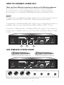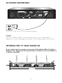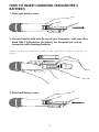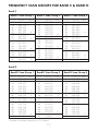
1
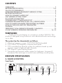
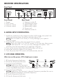
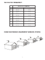
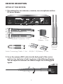
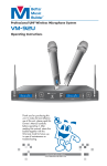
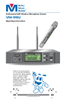
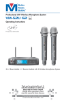
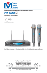
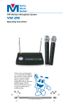
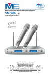
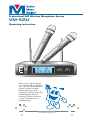
TM
®
Professional UHF Wireless Microphone System
VM-52U
Operating Instructions
BATT
ON
MU
TE
OFF
BA
M
ON
UT
TT
E
OF
F
UH
TM
AL
F DU
F
D
AL
er
IR
ett
W
B
IC
TM
M
SS
M
us
EL
E
ic
r
®
U
2
-5
U
M
V
de
uil
EM
B
ST
SY
-52
VM
ilder ®
STEM
Bu
S SY
ELES
U
rM
usic
WIR
tte
H
U
Be
MIC
F
H
F
U
UH
Better Music Builder UHF WIRELESS SYSTEM VM-52U
®
RF AF
POWER
CH
CH
01
733.78
02
738.59
MHz
RF AF
MIN
MHz
UHF
Thank you for purchasing this
unit. To make full and effective
use of this unit, please read this
Owner's Manual carefully
before operating it. After
reading this manual, retain this
booklet together with the
Warranty Card for future use
in case of maintenance or
troubleshooting.
Passionate about Music
www.BetterMusicBuilder.com
MAX
MIN
MAX
CONTENTS
FOREWORD.......................................................................................... 2
RECEIVER SPECIFICATION.................................................................. 3~4
VM-52U FCC FREQUENCY..................................................................... 5
HOME ELECTRONICS EQUIPMENT WIRELESS SYSTEM............................. 5
RECEIVER DESCRIPTION......................................................................... 6
HOW TO CONNECT AUDIO OUT.......................................................... 7
UHF WIRELESS SYSTEM CHART.............................................................. 7
DC-POWER CONNECTION.................................................................... 8
OPTIONAL FOR 19” RACK MOUNT KIT.................................................. 8
HANDHELD TRANSMITTER (Wireless Mic.) SPECIFICATION...................... 9
HOW TO INSERT HANDHELD TRANSMITTER’S BATTERIES......................10
HOW TO TURN ON AND OFF TRANSMITTER........................................11
CAUTION............................................................................................ 12
FREQUENCY SCAN GROUPS FOR BAND C & BAND D......................... 13
US UHF WIRELESS OPERATING FREQUENCIES................................ 14~15
FOREWORD
Thank you for purchasing our company’s product VM-52U. This
product is designed using America’s most advanced audio technology
up to date.
The system has the characteristic as follows:
1. Working frequency range: UHF520-810MHz (tunable)
2. CPU control: PLL frequency compose technique)
3. CPU controlled true diversity system for advance break up and
receiver control of left and right channels
4. LCD (Liquid Crystal Display) screen
5. Transmitter and receiver audio system for high-pass, low-pass &
band-pass filter technique to avoid noise and keep sound quality
RECEIVER SPECIFICATION
A. NAMES & FUNCTION:
Front Panel:
®
Better Music Builder UHF WIRELESS SYSTEM VM-52U
RF AF
POWER
1
CH
CH
01
733.38
12
738.59
MHz
RF AF
MHz
MIN
MAX
MIN
MAX
UHF
2
3
2
4
RECEIVER SPECIFICATION
Rear Panel:
AUDIO OUTPUT
TM
Better Music Builder ®
DC-POWER
MODEL NO. VM-52U
A&B
CALIFORNIA, UNITED STATES OF AMERICA
Comments? E-mail: [email protected]
www.BetterMusicBuilder.com
ENGINEERED AND DESIGN IN U.S.A.
SERIAL NO.
0
ANTENNA-B
BNC-50Ω
5
Front Panel:
1. Power
2. LCD screen
3. Volume control
4. Volume control
1/4 MIX ED
6
BALANCED-B
BALANCED-A
7
36120060908-21
3
RISK OF ELECTRIC SHOCK
DO NOT OPEN
Taking apart or modifying the
receiver may lead to electric shock,
fire, or damage to the receiver and
will void your warranty.
8
DC 13~18V
350mA
9
ANTENNA-A
BNC-50Ω
10
Rear Panel:
5. Antenna socket B
6. Unbalanced output
7. Balanced-B output
8. Balanced-A output
9. Power jack
10. Antenna socket A
B. MODEL SETUP SPECIFICATION:
1. Install two antennas to the antenna socket A & B of the rear panel, the
direction between them should be adjusted about 90°.
NOTE Do not install in too firmly or it may damage your system’s
antenna output.
2. Insert the DC power to the rear panel of your system.
NOTE Only use a DC 13~15v DC power, if you use any other power
voltage other than DC 13~15v you may damage the system. Your
warranty may be terminated if you damage it like this.
3. Turn on the power button that the LCD screen will be on.
4. Adjust the receiver’s status to your liking.
5. Turn off power the LCD screen will automatically shut off.
C. LCD PANEL OPERATION:
After turn on the power, LCD is light up as screen:
3
4
2
1. RF (radio frequency) Indicator
2. AF (audio frequency) Indicator
CH
CH
RF AF
RF AF
1
3. Current Channel Display
01
02
NOTE Make sure your receiver’s
733.78 738.59
channel/frequency matches the one
in your handheld transmitter’s channel/frequency.
4. Current Channel Display
NOTE Make sure your receiver’s channel/frequency matches the one in
your handheld transmitter’s channel/frequency.
5. RF (radio frequency) Indicator
6. AF (audio frequency) Indicator
MHz
3
MHz
5
6
E. OPERATING RECEIVER (7
GROUP) FREQUENCY DISPLAY
DIAGRAM
D. UHF FREQUENCIES:
There are a total of 14 different
frequencies for selection as shown in
the diagram.
Group A
RF AF
RF AF
CH
CH
01
747.10
02
802.60
MHz
RF AF
MHz
CH
CH
01
747.10
MHz
02
802.60
CH
CH
03
743.03
MHz
04
766.71
RF AF
MHz
Group B
NOTE
These 14 frequencies are
default set by the manufacturer.
Therefore, you cannot change them.
RF AF
Each wireless system has two
built-in UHF frequencies, so these 14
different frequencies are set into 7
groups from A to G. If you use more
than two frequencies (for channel), you
may purchase a different group of
frequencies. For example, if you have
the group A for frequency, then you
need to purchase the group other than
A (i.e. from B to G). Otherwise, the
frequencies will be interrupted.
However, if you find some interruptions
in your wireless system within 200
feet, there is possibility that you may
use the same frequency in your area.
Therefore, you need to change the
frequency in your wireless system, or
you may need to upgrade your
wireless system. For upgrading your
wireless system, we recommend you to
purchase the VM-92U because it has
32 different UHF frequencies for
selection.
4
RF AF
MHz
Group C
RF AF
CH
CH
05
738.59
06
763.38
MHz
RF AF
MHz
Group D
RF AF
CH
CH
07
733.78
08
759.68
MHz
RF AF
MHz
Group E
RF AF
CH
CH
09
756.72
MHz
10
796.68
CH
CH
11
774.11
MHz
12
808.15
CH
CH
13
781.88
MHz
14
810.74
RF AF
MHz
Group F
RF AF
RF AF
MHz
Group G
RF AF
RF AF
MHz
VM-52U FCC FREQUENCY
VM-52U FCC Frequency
Group
A
B
C
D
E
F
G
Receiver Frequency
Transmitter Frequency
747.10
CH 01
802.60
CH 02
743.03
CH 03
766.71
CH 04
738.59
CH 05
763.38
CH 06
733.78
CH 07
759.68
CH 08
756.72
CH 09
796.68
CH 10
774.11
CH 11
808.15
CH 12
781.88
CH 13
810.74
CH 14
HOME ELECTRONICS EQUIPMENT WIRELESS SYSTEM
5
RECEIVER DESCRIPTION
SETTING UP YOUR RECEIVER:
1. The package has two antennas, a receiver, two microphones and one
DC power adaptor.
TM
AUDIO OUTPUT
Better Music Builder ®
MODEL NO. VM-52U
DC-POWER
CALIFORNIA, UNITED STATES OF AMERICA
Comments? E-mail: [email protected]
www.BetterMusicBuilder.com
ENGINEERED AND DESIGN IN U.S.A.
A&B
SERIAL NO.
0
ANTENNA-B
BNC-50Ω
1/4 MIX ED
BALANCED-B
BALANCED-A
36120060908-21
3
RISK OF ELECTRIC SHOCK
DO NOT OPEN
Taking apart or modifying the
receiver may lead to electric shock,
fire, or damage to the receiver and
will void your warranty.
DC 13~18V
350mA
ANTENNA-A
BNC-50Ω
BATT
ON
MUTE
OFF
BATT
ON
MUTE
OFF
Receiver: 1 Set
TM
Better Music Builder ®
UHF
UHF DUAL MIC WIRELESS SYSTEM VM-52U
TM
Better Music Builder ®
UHF
UHF DUAL MIC WIRELESS SYSTEM VM-52U
DC Power
Adapter: 1 Unit
Handheld Transmitter: 2 Set
AA
ALKA
LI
BATT NE
ERY
ALKA
LI
BATT NE
ERY
AA
AA
ALKA
LI
BATT NE
ERY
Audio Connecting Cable: 1 Unit
ALKA
LI
BATT NE
ERY
AA
Receiving
Antenna:
2 Units
AA (R6 1.5V) Battery: 4 Units
2. Screw the antennas BNC socket into the back panel of the receiver
and turn it in clockwise to lock it as shown in the following diagram.
You can adjust the antennas into different angles for receiving good
signals.
ANTENNA-B
BNC-50Ω
6
HOW TO CONNECT AUDIO OUT
There are three different connectors as shown in the following diagram:
• Connector A is a mixed audio output (Channel A and Channel B)
• Connector B is a channel B XLR-balanced audio out (Group B Mic.)
• Connector C is a channel A XLR-balanced audio out (Group A Mic.)
NOTE
Connector A is an unbalanced audio signal. If you connect A to the mixer or
amplifier, then both MIC. A and MIC. B will have the same effect.
Connector B is a balanced XLR audio signal. If you connect B to the mixer or
amplifier, then you can control the microphone effect on MIC. B only.
Connector C (Balanced A) is a balanced XLR audio signal. If you connect A
to the mixer or amplifier, then you can control the microphone effect on MIC.
A only.
TM
AUDIO OUTPUT
Better Music Builder ®
MODEL NO. VM-52U
DC-POWER
CALIFORNIA, UNITED STATES OF AMERICA
Comments? E-mail: [email protected]
www.BetterMusicBuilder.com
ENGINEERED AND DESIGN IN U.S.A.
A&B
SERIAL NO.
0
ANTENNA-B
BNC-50Ω
1/4 MIX ED
BALANCED-B
A
B
36120060908-21
3
RISK OF ELECTRIC SHOCK
DO NOT OPEN
Taking apart or modifying the
receiver may lead to electric shock,
fire, or damage to the receiver and
will void your warranty.
BALANCED-A
ANTENNA-A
BNC-50Ω
DC 13~18V
350mA
C
Channel A Handheld Transmitter
OFF
BATT
UHF
Better Music Builder ®
UHF DUAL MIC WIRELESS SYSTEM VM-52U
ON
MUTE
TM
OFF
BATT
ON
MUTE
UHF WIRELESS SYSTEM CHART
TM
Better Music Builder ®
UHF
UHF DUAL MIC WIRELESS SYSTEM VM-52U
Channel B Handheld Transmitter
TM
AUDIO OUTPUT
Better Music Builder ®
MODEL NO. VM-52U
DC-POWER
CALIFORNIA, UNITED STATES OF AMERICA
Comments? E-mail: [email protected]
www.BetterMusicBuilder.com
ENGINEERED AND DESIGN IN U.S.A.
A&B
SERIAL NO.
0
ANTENNA-B
BNC-50Ω
Rear View
1/4 MIX ED
BALANCED-B
BALANCED-A
36120060908-21
3
RISK OF ELECTRIC SHOCK
DO NOT OPEN
Taking apart or modifying the
receiver may lead to electric shock,
fire, or damage to the receiver and
will void your warranty.
DC 13~18V
350mA
ANTENNA-A
BNC-50Ω
Balance Connection
XLR
XLR
XLR
XLR
Balance Input Balance Input Balance Input Balance Input
1/4"
1/4"
1/4"
1/4"
Unbalance Input Unbalance Input Unbalance Input Unbalance Input
Audio Mixer Amplifier or a Karaoke Unit Input terminal
7
DC-POWER CONNECTION
TM
AUDIO OUTPUT
DC-POWER
Better Music Builder ®
MODEL NO. VM-52U
CALIFORNIA, UNITED STATES OF AMERICA
Comments? E-mail: [email protected]
www.BetterMusicBuilder.com
ENGINEERED AND DESIGN IN U.S.A.
A&B
SERIAL NO.
0
ANTENNA-B
BNC-50Ω
1/4 MIX ED
BALANCED-B
36120060908-21
3
RISK OF ELECTRIC SHOCK
DO NOT OPEN
Taking apart or modifying the
receiver may lead to electric shock,
fire, or damage to the receiver and
will void your warranty.
BALANCED-A
ANTENNA-A
BNC-50Ω
DC 13~18V
350mA
Rear View
120V AC DC-13~18V 350mA adaptor
NOTE
If you use 220V to 240V, you must make sure to use a right adaptor,
otherwise, it would damage your system. Our warranty does not cover this.
OPTIONAL FOR 19” RACK MOUNT KIT
If you want to put two systems onto a mount-kit, please follow the below
diagram. Our design has this special feature to allow it rack mountable, so
it can be removable.
®
®
Better Music Builder UHF WIRELESS SYSTEM VM-52U
RF AF
POWER
CH
CH
05
763.38
11
743.03
MHz
Better Music Builder UHF WIRELESS SYSTEM VM-52U
RF AF
MHz
RF AF
MIN
MAX
MIN
CH
05
763.38
MAX
UHF
POWER
UHF
19 inches
8
CH
MHz
11
743.03
RF AF
MHz
MIN
MAX
MIN
MAX
HANDHELD TRANSMITTER (Wireless Mic.) SPECIFICATION
NAMES & FUNCTION:
Better Music Builder ®
UHF
UHF DUAL MIC WIRELESS SYSTEM VM-52U
3
AA1.5V
FREQUENCY
2
TM
OFF
BATT
1
ON
MUTE
Uncover Looking of the Handheld Transmitter:
4
AA
ALKALINE
BATTERY
AA
ALKALINE
BATTERY
FREQUENCY
5
1. Condenser and grille
2. Battery power indicator light: If light is flashing this means battery power is low
and must be replaced, if light is not flashing battery is at normal power.
3. Easily-accessible power switch ON/OFF/MUTE
4. Battery dock: insert 2x1.5V AA battery or 2x1.2V rechargeable battery.
5. Battery Cover: Insert 2 “AA” batteries into the battery slot, putting battery’s
polarity on different ends may damage system and your warranty may be
terminated if damage does occur because of it.
9
HOW TO INSERT HANDHELD TRANSMITTER’S
BATTERIES
FREQUENCY
1. Slide open battery cover.
2. Use one hand to hold onto the top of your transmitter, with your other
hand slide 2 AA batteries into battery slot. Becareful not to drop
transmitter while inserting batteries.
AA
ALKALINE
BATTERY
FREQUENCY
Make sure that you insert the battery at the right electric poles, as shown in
picture.
FREQUENCY
3. Slide back battery cover.
10
HOW TO TURN ON AND OFF TRANSMITTER
OFF
ON
MUTE
When the power light is flashing, that
indicates that the transmitter’s battery is low.
If there is no light at all, battery is out of power.
NOTE
BATT
Click the power switch to turn on/off your transmitter. When on transmitter’s
light will be on, when off transmitter’s light will be off.
TECHNICAL SPECIFICATION
A. SYSTEM FEATURE:
1.
2.
3.
4.
5.
6.
7.
8.
9.
10.
Channel: 2
Frequency Range: 700MHz~900MHz (Selectable)
Modulation Mode: FM
Maximum Frequency Deviation: ± 45KHz
Audio Frequency Response: 35Hz~20KHz
Frequency Setup Mode: PLL
Receiver Dimensions (WxHxD): 8.27x1.97x7.5 (inches)/21x5x19 (cm)
Handheld Transmitter Dimensions (WxH): x1.7x10.4 (inches)/4.4x26.5 (cm)
Net Weight: 3.8 lbs / 1.7 kg
Shipping Weight: 5.8 lbs / 2.6 kg
B. TECHNOLOGICAL FEATURE OF THE TRANSMITTER:
1. Transmitter: 10mW
2. Oscillation Mode: PLL
3. Adjustment Mode: FM
4. Image Controlment: -50dB
5. Power: DC 2.4V~7.2V (DC 1.2Vx2x3 or 1.5x2)
6. Battery: 2 PCS AA Type Alkaline Battery
C. TECHNOLOGICAL FEATURE OF THE RECEIVER:
1.
2.
3.
4.
5.
6.
Sensitivity: 2.0uV
Sensitivity Adjustment Range: 12~32dB BUV
Stray Control: > 75dB
Output Level: Balance Output: 0~0.5V/100, Sound Output: 0~0.5V/5K
Power: 13~18V DC
Work Current: 350mA
11
CAUTION
1. When the receiver is on, the red light repeatedly flash on the transmitter, it
means that the receiver or the transmitter is damaged, please send to the
manufacturer.
2. If you are using several systems, please change the frequency carefully, to
avoid interfering with other signals.
3. The input power voltage of receiver’s outside power is 200V (±10%), it may
effect the receiver if it is lower or higher than the given rate.
4. When inserting the battery into the transmitter, avoid putting the polarity in an
opposite direction, or it may be damaged. (If damage occurs because of this
your warranty may be terminated)
5. When selecting sensitivity of the receiver, the least figure you should select
should be 15dB, or the signal will be worse in a further distance.
Caution: To reduce the risk of electrical shock, do
not remove the cover (or back). No user serviceable
parts inside: refer servicing to qualified personnel.
RISK OF ELECTRIC SHOCK
DO NOT OPEN
Warning: To reduce the risk of fire or electrical
shock, do not expose this appliance to rain or
moisture.
This symbol, wherever it
appears, alerts you to
important operating and
maintenance instructions in
the accompanying literature.
Read the manual.
12
This symbol, wherever it
appears, alerts you to the
presence of uninsulated
dangerous voltage inside the
enclosure voltage that may be
sufficient to constitute a risk of
shock.
FREQUENCY SCAN GROUPS FOR BAND C & BAND D
Band C
Band C Scan Group 1
Band C Scan Group 2
Band C Scan Group 3
TV Ch. Frequency – MHz *
25
(None)
0
26
542.750
26
545.500
26
547.125
26
547.375
4
27
549.750
27
550.375
27
550.625
3
28
557.250
28
557.500
28
559.250
28
559.500
4
29
562.000
29
563.375
29
563.625
3
30
566.000
30
566.250
2
TV Ch. Frequency – MHz *
25
541.500
1
26
542.750
26
544.375
26
544.750
26
545.750
26
547.500
5
27
(None)
0
28
554.250
28
556.125
28
557.500
28
559.375
4
29
560.000
29
561.875
29
562.250
29
563.250
29
565.500
5
30
566.000
1
TV Ch. Frequency – MHz *
25
541.500
1
26
542.125
26
543.500
26
544.000
26
546.250
4
27
548.250
27
549.750
2
28
555.750
28
556.625
28
558.250
28
559.375 4
29
560.125
29
561.500
29
564.000
29
564.250
4
30
566.125
1
Band D Scan Group 1
Band D Scan Group 2
Band D Scan Group 3
TV Ch. Frequency – MHz *
44
655.500
1
45
658.000
45
658.375
45
659.250
45
659.500
45
661.500
5
46
662.375
46
662.750
2
47
669.625
47
671.750
2
48
674.750
48
675.750
48
676.125
48
678.000
48
678.250
48
679.500
6
49
(None)
0
TV Ch. Frequency – MHz *
44
655.875
1
45
656.250
45
658.500
45
659.750
45
660.000
45
660.500
5
46
664.375
46
665.500
2
47
671.625
47
672.000
2
48
674.000
48
674.500
48
675.750
48
676.750
48
678.250
5
49
680.250
1
49
(None)
0
TV Ch. Frequency – MHz *
44
655.500
44
655.750
2
45
656.625
45
658.500
45
658.750
45
659.500
4
46
662.750
46
665.250
2
47
671.250
47
672.375
47
673.125
3
48
674.125
48
674.500
48
675.375
48
678.625
48
679.125
5
Band D
* Number of wireless frequencies in TV Channel.
13
US UHF WIRELESS OPERATING FREQUENCIES
Band C: 541.500 - 566.375 MHz
TV Ch.
25
---
---
---
---
541.500 541.625 541.750 541.875
26
542.000 542.125 542.250 542.375 542.500 542.625 542.750 542.875
26
543.000 543.125 543.250 543.375 543.500 543.625 543.750 543.875
26
544.000 544.125 544.250 544.375 544.500 544.625 544.750 544.875
26
545.000 545.125 545.250 545.375 545.500 545.625 545.750 545.875
26
546.000 546.125 546.250 546.375 546.500 546.625 546.750 546.875
26
547.000 547.125 547.250 547.375 547.500 547.625 547.750 547.875
27
548.000 548.125 548.250 548.375 548.500 548.625 548.750 548.875
27
549.000 549.125 549.250 549.375 549.500 549.625 549.750 549.875
27
550.000 550.125 550.250 550.375 550.500 550.625 550.750 550.875
27
551.000 551.125 551.250 551.375 551.500 551.625 551.750 551.875
27
552.000 552.125 552.250 552.375 552.500 552.625 552.750 552.875
27
553.000 553.125 553.250 553.375 553.500 553.625 553.750 553.875
28
554.000 554.125 554.250 554.375 554.500 554.625 554.750 554.875
28
555.000 555.125 555.250 555.375 555.500 555.625 555.750 555.875
28
556.000 556.125 556.250 556.375 556.500 556.625 556.750 556.875
28
557.000 557.125 557.250 557.375 557.500 557.625 557.750 557.875
28
558.000 558.125 558.250 558.375 558.500 558.625 558.750 558.875
28
559.000 559.125 559.250 559.375 559.500 559.625 559.750 559.875
29
560.000 560.125 560.250 560.375 560.500 560.625 560.750 560.875
29
561.000 561.125 561.250 561.375 561.500 561.625 561.750 561.875
29
562.000 562.125 562.250 562.375 562.500 562.62 5562.750 562.875
29
563.000 563.125 563.250 563.375 563.500 563.625 563.750 563.875
29
564.000 564.125 564.250 564.375 564.500 564.625 564.750 564.875
29
565.000 565.125 565.250 565.375 565.500 565.625 565.750 565.875
30
566.000 566.125 566.250 566.375
---
---
---
Avoid using same frequencies as TV channels or other radio signals for better performance.
14
---
Band D: 655.500 - 680.375 MHz
TV Ch.
44
---
---
---
---
655.500 655.625 655.750 655.875
45
656.000 656.125 656.250 656.375 656.500 656.625 656.750 656.875
45
657.000 657.125 657.250 657.375 657.500 657.625 657.750 657.875
45
658.000 658.125 658.250 658.375 658.500 658.625 658.750 658.875
45
659.000 659.125 659.250 659.375 659.500 659.625 659.750 659.875
45
660.000 660.125 660.250 660.375 660.500 660.625 660.750 660.875
45
661.000 661.125 661.250 661.375 661.500 661.625 661.750 661.875
46
662.000 662.125 662.250 662.375 662.500 662.625 662.750 662.875
46
663.000 663.125 663.250 663.375 663.500 663.625 663.750 663.875
46
664.000 664.125 664.250 664.375 664.500 664.625 664.750 664.875
46
665.000 665.125 665.250 665.375 665.500 665.625 665.750 665.875
46
666.000 666.125 666.250 666.375 666.500 666.625 666.750 666.875
46
667.000 667.125 667.250 667.375 667.500 667.625 667.750 667.875
47
668.000 668.125 668.250 668.375 668.500 668.625 668.750 668.875
47
669.000 669.125 669.250 669.375 669.500 669.625 669.750 669.875
47
670.000 670.125 670.250 670.375 670.500 670.625 670.750 670.875
47
671.000 671.125 671.250 671.375 671.500 671.625 671.750 671.875
47
672.000 672.125 672.250 672.375 672.500 672.625 672.750 672.875
47
673.000 673.125 673.250 673.375 673.500 673.625 673.750 673.875
48
674.000 674.125 674.250 674.375 674.500 674.625 674.750 674.875
48
675.000 675.125 675.250 675.375 675.500 675.625 675.750 675.875
48
676.000 676.125 676.250 676.375 676.500 676.625 676.750 676.875
48
677.000 677.125 677.250 677.375 677.500 677.625 677.750 677.875
48
678.000 678.125 678.250 678.375 678.500 678.625 678.750 678.875
48
679.000 679.125 679.250 679.375 679.500 679.625 679.750 679.875
49
680.000 680.125 680.250 680.375
---
---
---
Avoid using same frequencies as TV channels or other radio signals for better performance.
15
---
TM
®
Passionate about Music
www.BetterMusicBuilder.com
Printed on 100% Recycled Paper ©2007 Better Music Builder (USA) Comments E-mail to [email protected] All Rights Reserved in USA.