1
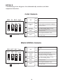
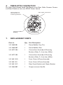
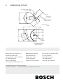
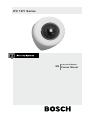
LTC 1271 Series
Instruction Manual
EN Corner Mount
SAFETY PRECAUTIONS
CAUTION:TO REDUCE THE RISK OF ELECTRICAL
SHOCK, DO NOT OPEN COVERS. NO USER SERVICEABLE PARTS INSIDE. REFER SERVICING TO QUALIFIED
SERVICE PERSONNEL.
This label may appear on the bottom of the unit due to space limitations.
The lightning flash with an arrowhead symbol within an equilateral
triangle is intended to alert the user to the presence of uninsulated "dangerous voltage" within the product's enclosure that may be
of sufficient magnitude to constitute a risk of electric shock to
persons.
The exclamation point within an equilateral triangle is intended to
alert the user to presence of important operating and maintenance
(servicing) instructions in the literature accompanying the appliance.
WARNING: TO PREVENT FIRE OR SHOCK HAZARD, DO
NOT EXPOSE UNITS TO RAIN OR MOISTURE.
Attention: Installation should be performed by qualified service personnel only in accordance with the National Electrical
Code or applicable local codes.
24 VAC Units: Do Not Exceed 30 VAC Input.Voltage applied to the unit’s
power input should not exceed 30VAC. Normal input voltage is 24 VAC. User
supplied wiring from 24 VAC supply to unit must be in compliance with electrical codes (Class 2 power levels). Do not ground 24 VAC supply at power
supply terminals or at unit’s power supply terminals.
2
SECURITE
DANGER: POUR ÉVITER TOUT RISQUE D'ÉLECTROCUTION,
NE PAS OUVRIR LE BOÎTIER. IL N'Y A PAS DE PIÈCES REMPLAÇABLES À L'INTÉRIEUR. POUR TOUTE RÉVISION,
S'ADRESSER À UN TECHNICIEN SPÉCIALISÉ.
En raison de limitation de place, cette étiquette peut être placée sur le dessous
de l'appareil.
L'éclair fléché dans un triangle équilatéral, avertit l'utilisateur de la
présence d'une "tension dangereuse" non isolée à l'intérieur de l'appareil et d'une valeur suffisante pour constituer un risque d'électrocution.
Le point d'exclamation contenu dans un triangle équilatéral, avertit
l'utilisateur de la présence, dans la documentation qui accompagne
l'appareil, de consignes d'utilisation et de maintenance importantes.
ATTENTION: POUR ÉVITER LE RISQUE D'ÉLECTROCUTION OU
D'INCENDIE, NE PAS
EXPOSER À LA PLUIE OU À L'HUMIDITÉ UN APPAREIL.
Attention: L'installation doit être effectuée uniquement par du
personnel de service qualifié conformément à la réglementation
du Code Electrique National ou à la réglementation locale.
Appareils 24 VCA
Ne pas excéder 30 VCA. La tension appliquée à l'entrée d'alimentation de l'appareil ne devrait pas excéder 30 VCA.Toute installation électrique fournissant
du 24 Volts courant alternatif doit être conforme aux codes électriques.
(Niveaux d'alimentation de la Classe 2). Ne pas brancher une prise de terre
sur les bornes d'alimentation 24 Volts ou aux bornes d'alimentation de l'appareil.
3
SICHERHEITSVORKEHRUNGEN
VORSICHT: UM EINEN ELEKTRISCHEN SCHLAG ZU VERMEIDEN, ABDECKUNG NICHT ENTFERNEN.WARTUNGEN
ALLER ART QUALIFIZIERTEM PERSONAL ÜBERLASSEN.
Aus Platzgründen kann diese Warnung auf der Unterseite des Gerätes angebracht sein.
Das Blitzsymbol im gleichseitigen Dreieck soll den Benutzer auf
nicht isolierte "Hochspannung" im Gehäuse aufmerksam machen,
die eventuell stark genug ist, um einen elektrischen Schlag zu verursachen.
Das Ausrufezeichen im gleichseitigen Dreieck soll den Benutzer auf
wichtige Bedienungs- und Wartungsanleitungen in der dem Gerät
beigefügten Literatur aufmerksam machen.
WARNUNG: UM FEUER ODER ELEKTRISCHE SCHLÄGE ZU
VERMEIDEN, SETZEN SIE DAS GERÄT NIEMALS REGEN ODER
FEUCHTIGKEIT AUS.
Achtung! Die Installation sollte nur von qualifiziertem
Kundendienstpersonal gemäß jeweilig zutreffender
Elektrovorschriften ausgeführt werden.
24 VAC Geräte
Achtung! 30 Volt Eingangswechselspannung darf für 24 VAC Modelle nicht
überschritten werden. Normal-betrieb findet bei 24 Volt Wechselspannung
statt. Die Kabel- bzw. Drahtverbindung vom Netzgerät zu dem vor-liegenden
Gerät muß die Bestimmungen der Schutz-klasse II erfüllen. Nicht die 24-VoltLeitung erden weder am Netzgerät noch an den Anschlußklemmen des vorliegenden Gerätes
4
PRECAUCIONES DE SEGURIDAD
PRECAUCION: PARA REDUCIR EL RIESGO DE CHOQUE
ELÉCTRICO, FAVOR NO ABRIR LA CUBIERTA. ESTE EQUIPO
NO CONSTA DE PIEZAS O PARTES QUE REQUIEREN SERVICIO
O MANTENIMIENTO. PARA REPARACIONES FAVOR REFERIRSE
A UN TÉCNICO CALIFICADO.
Debido a limitaciones de espacio, esta etiqueta puede aparecer en la parte inferior
de la unidad.
El símbolo representado por un relámpago con punta de flecha
dentro de un triángulo equilátero, se muestra con el objetivo de
alertar al usuario que existen "voltages peligrosos" sin aislamiento,
dentro de la cubierta de la unidad. Dichos voltages pueden ser de
tal magnitud que constituyen un riesgo de choque eléctrico a personas.
El símbolo de exclamación dentro de un triángulo equilátero, se
muestra con el objetivo de alertar al ususario de que instrucciones
de operación y mantenimiento importantes acompañan al equipo.
PELIGRO: PARA EVITAR EL PELIGRO DE INCENDIO Ó CHOQUE
ELÉCTRICO, NO EXPONGA A LA LLUVIA Ó HUMEDAD.
Atención: La instalación de este equipo debe ser realizada por
personal capacitado, solo en acuerdo, y en cumplimiento de normas del "National Electric Code" (Código Eléctrico Nacional) ó las
normas del Gobierno Nacional Local.
Unidades de 24 VCA
No exceder 30 VCA de entrada.Voltage suplido a la unidad no debe exceder
30 VCA.Voltage de entrada normal es de 24 VCA. El cableado de 24 VCA
provisto por el usuario debe cumplir con las normas eléctricas (Clase 2 de
niveles de alimentación). No conectar los 24 VCA a tierra en las terminales de
la alimentación ó a las terminales de la fuente de alimentación de la unidad.
5
FCC & ICES INFORMATION
(U.S.A. and Canadian Models Only)
WARNING - This equipment has been tested and found to comply with the limits for a
Class A digital device, pursuant to Part 15 of the FCC Rules and ICES-003 of Industry
Canada.These limits are designed to provide reasonable protection against harmful interference when the equipment is operated in a commercial environment.This equipment
generates, uses, and can radiate radio frequency energy and, if not installed and used in
accordance with the instruction manual, may cause harmful interference to radio communications. Operation of this equipment in a residential area is likely to cause harmful
interference in which case the user will be required to correct the interference at his
own expense. Intentional or unintentional changes or modifications not expressly
approved by the party responsible for compliance shall not be made. Any such changes
or modifications could void the user's authority to operate the equipment.
If necessary, the user should consult the dealer or an experienced radio/television technician for corrective action.The user may find the following booklet prepared by the
Federal Communications Commission helpful: "How to Identify and Resolve Radio-TV
Interference Problems." This booklet is available from the U.S. Government Printing
Office,Washington, DC 20402, Stock No.004-000-00345-4.
Warning: This is a Class A product. In a domestic environment, this
product may cause radio interference in which case the user may be
required to take adequate measures.
1.
UNPACKING
Unpack carefully.This is an electromechanical device and should be handled
carefully. Check to ensure that the following items are included:
•
Housing
•
Camera Module
•
Hardware Kit:
Extra tamper-resistant screw
Tamper-resistant hex bit wrench
2 conduit hole plugs.
2.
SERVICE
If the unit ever needs repair service, the customer should contact the nearest
Bosch Security Systems, Inc. Service Center for authorization to return and
shipping instructions.
Service Centers
U.S.A.: 800-366-2283 or 408-956-3895
Fax: 800-366-1329 or 408-956-3896
Email: [email protected]
Canada: 514-738-2434
Europe, Middle East & Asia Pacific Regions
800-366-2283
For additional information, see www.boschsecuritysystems.com
6
3.
DESCRIPTION & SPECIFICATIONS
The LTC 127x Series Corner Phortress units are small, high security
surveillance cameras for corner applications.
ELECTRICAL
Model No.
Description
Voltage Range
Power
LTC 1271/10C
Color, varifocal
21 to 27 VAC, 50 Hz or 11 to 13 VDC
3.0 W
LTC 1271/10CS
Color, varifocal
21 to 27 VAC, 50 Hz or 11 to 13 VDC
3.0 W
LTC 1271/10CF
Color Varifocal
21 to 27 VAC, 50Hz
6.6W
LTC 1271/10CSF
Color Varifocal
21 to 27 VAC, 50Hz
6.6W
LTC 1271/20C
Color, varifocal
21 to 27 VAC, 60 Hz or 11 to 13 VDC
3.0 W
LTC 1271/20CS
LTC 1271/20CF
Color, varifocal
Color Varifocal
21 to 27 VAC, 60 Hz or 11 to 13 VDC
21 to 27 VAC, 60Hz
3.0 W
6.6W
LTC 1271/20CSF
Color Varifocal
21 to 27 VAC, 60Hz
6.6W
PAL:
NTSC:
CAMERA
Horizontal Resolution: 480 TVL.
LENS
Focal Length: Integral 2–4 mm varifocal.
Iris: Auto DC control iris; F1.6–200 iris range.
Format: 1/4-inch.
MECHANICAL
Construction/Finish: Polycarbonate dome and cast aluminum housing.
4.
INSTRUCTIONS
1. Check to make sure you have received the corner Phortress housing and
the separate camera module.
2. Disassemble housing using provided security wrench.
3. Using rear cover as a template, mark screw holes on the corner wall
(see Figure 1).
Camera Module with
Mounting Bracket
Conduit plugs, 2 supplied;
use where required
Back Cover
Front Cover
Tamper-resistant screw;
use wrench supplied.
Figure 1 LTC 1271 Corner Phortress
7
4. Decide which conduit hole will be used and plug remaining openings using
the 2 plugs provided in the hardware kit.The conduit plug on top of the unit
may be secured by tightening the set screw at the back of the rear cover.
This must be done before the back cover is secured to the wall. Use a 2.5
mm Hex Key (not supplied).
5. Drill hole for conduit and run wiring.
6. Use 6 mm (1/4-inch) bolts with appropriate anchors for the type of wall
construction.
WARNING: THE CORNER PHORTRESS CAN WITHSTAND 300 LB OF STATIC
DOWNWARD LOAD IF APPROPRIATE BOLTS AND ANCHORS ARE
EMPLOYED.
7. Remove the camera module from packaging.
8. Loosen the nut located on the back plate approximately 6 turns without
removing, and insert camera bracket between the nut and retaining
bracket (see Figure 2).
Top Bracket
Nut; loosen but
do not remove.
Install camera bracket
between top bracket and nut.
Figure 2 Rear Plate Exploded View
9. Tighten nut securely.
10. Adjustability: Camera/lens is fully adjustable. See (Figure 3) for adjustment points.
Forward/back adjustment;
use 10mm wrench.
Tilt adjustment;
Thumb nut
Rotate adjustment dial;
Used to square camera
once adjustments have
been made.
Position camera as desired
and tighten fasteners securly.
Do not overtighten!
Entire base bracket rotates
for pan adjustment
Vertical adjustment; Phillips
screw & nut (two places)
Figure 3 Camera Position Adjustment Points
11. Replace cover and secure using the supplied tamper-resistant screw (See
Figure 1).
8
5. CAMERA AND LENS SETTINGS
Camera module has various settings for any additional adjustments
that may be required. See figure 4 and 5 for adjustment locations.
5.1 Phase Adjust
The phase adjust control is located on the power board next to power cable
connections (see figure 4).To adjust phase, use a small screwdriver to rotate
control (blue block with yellow screw hole) until picture is synchronized with
other cameras in the system.
Phase Adjust Pot on Power Board
Figure 4 Camera Assembly
5.2 Dip Switch Location
See Detail B for dip switch information.
Dip Switch Locations
See Detail B for Switch Positions
.
Figure 5 Dip Switch Location
9
DETAIL B
The following chart diagrams the selectable dip switches and their
respective functions:
Color Camera
IRIS FL BLC Sync
1
DC ON ON INT
2
3
1
Note:
2
3
DC
IRIS
Flickerless
(FL)
Backlight
Compensation
(BLC)
4
4
is factory set up
Synchronization
Mode
DC IRIS
AES AES
ON Shutter speed to be fixed at 1/100 sec.
OFF Normal position
Set to this position when a strong
light is in the back ground.
OFF Normal position
ON
INT Internal Synchronization mode
L.L.
Line lock mode
Black & White Camera
IRIS AGC BLC Sync
1
DC OFF ON INT
2
DC
IRIS
Auto Gain
Control
(AGC)
3
1
Note:
2
3
is factory set up
Backlight
Compensation
(BLC)
4
4
Synchronization
Mode
10
DC IRIS
AES AES
OFF Gain Level to be fixed at min.
Set to this position to improve camera
ON sensitivity in low light conditions.
ON Set to this position when a strong
light is in the back ground.
OFF Normal position
INT Internal Synchronization mode
L.L.
Line lock mode
6.
FIBER OPTIC CONNECTION
For Fiber Optic Models, Avoid Tight Bends in the Fiber Cable. Connect Camera
and Fiber Module to the same 24VAC Power Source
Note Position of
Dip Switches for
Camera-up-Position.
Fiber Optic Connection.
Suggested Cable
Routing.
7.
REPLACEMENT PARTS
Part no.
Qty
Part Description
315 3460 001
1
Dome Bubble, Gray Tint
315 3460 002
1
Dome Bubble, Clear
315 4372 504
1
Camera/Lens Assembly & Mounting
Bracket (Color, 2–4 mm lens, 50Hz)
315 4372 503
1
Camera/Lens Assembly & Mounting
Bracket (Color, 2–4 mm lens, 60Hz)
315 3651 010
1
Front Cover & Dome Assembly
315 3651 011
1
Front Cover & Dome Assembly
315 3651 012
1
Fiber Optic Module with Mount Bracket
315 3466 802
1
Tamper-resistant Hex Bit
11
8.
DIMENSIONAL OUTLINE
3/4" THREADED CONDUIT OPENING
1 OF 3
TWO PLUGS SUPPLIED.
66.7
[ 2.63 ]
HOLE LOCATION
BOTH SIDES
90∞
50.8
[ 2.00 ]
CONDUIT HOLE LOCATION,
TYPICAL BOTH SIDES.
173.5
[ 6.83 ]
20.3
[ .80 ]
122.7
[ 4.83 ]
DIMENSIONS ARE MM
[INCHES]
171.3
[ 6.74 ]
83.6
[ 3.29 ]
41.9
[ 1.65 ]
177.1
[ 6.97 ]
92.1
[ 3.63 ]
99.31
[ 3.910 ]
ÿ 7.11
[ .280 ]
TWO HOLES
EACH SIDE.
CLOSURE SECURED WITH
TAMPER RESISTANT SCREW,
DRIVER BIT SUPPLIED.
Bosch Security Systems, Inc.
850 Greenfield Road
Lancaster, PA 17601 EE.UU.
Tel: 800-326-3270
Fax: 717-735-6560
www.boschsecuritysystems.com
Robert Bosch GmbH
Geschäftsbereich
Postfach 10 60 50
70049 Stuttgart
Telefax (0711) 811-1234
@ 2003 Bosch Security Systems GmbH
100 0091 001 BOS
11/03 Data subject to change without notice.
Bosch Security Systems B.V.
P.O. Box 80002
5600 JB Eindhoven
The Netherlands
Tele +31 40 27 80000