1
Use, Care, and Installation Guide
www.zephyronline.com
CACHE
CCA-E30ASX
CCA-E36ASX
CCA-E48ASX
Model number:
Serial Number:
Date of Purchase:
Sales Dealer:
DEC06.0101 © Zephyr Corporation
READ AND SAVE THESE INSTRUCTIONS
www.zephyronline.com
INSTALLATION
Ducting Calculation Sheet .......................................
Mounting Height & Clearance................................
Ducting Options ...........................................................
+RRG6SHFL¿FDWLRQV ...................................................
Preparing the Electrical Wires ...............................
Internal Blower (Vertical Ducting).........................
Internal Blower (Horizontal Ducting) ...................
External Blower Prepartion .....................................
Mounting the Range Hood ......................................
5
6
7
8
9
10-11
12-13
14
15
FEATURES & CONTROLS
Touch Controls ............................................................. 16
MAINTENANCE
Cleaning and Installing Filters ............................... 17
Lights ................................................................................ 18
TROUBLESHOOTING................................................................ 19
1
Table of Contents
SAFETY NOTICE ................................................................. 2-3
LIST OF MATERIALS ....................................................... 4
www.zephyronline.com
Important Safety Notice
READ AND SAVE THESE INSTRUCTIONS
WARNING
TO REDUCE THE RISK OF FIRE OR ELECTRIC SHOCK, DO NOT USE THIS FAN WITH ANY SOLID-STATE CONTROL DEVICE.
WARNING
TO REDUCE THE RISK OF FIRE ELECTRIC SHOCK, OR INJURY TO PERSONS, OBSERVE THE FOLLOWING:
a. Use this unit only in the manner intended by the manufacturer, if you have questions, contact the manufacturer.
b. Before servicing or cleaning unit, switch power off at service panel and lock panel to prevent power from being switched on accidentally.
When the service disconnecting means cannot be locked, securely fasten a prominent warning device, such as a tag, to the service
panel.
CAUTION
For general ventilating use only. Do not use to exhaust hazardous or explosive materials and vapors. Take care when using cleaning
agents or detergents. Suitable for use in household cooking area.
WARNING
TO REDUCE THE RISK OF RANGE TOP GREASE FIRE:
a. Never leave surface units unattended at high settings. Boilovers cause smoking and greasy spillovers that may ignite. Heat oils slowly
on low or medium settings.
E $OZD\VWXUQKRRG21ZKHQFRRNLQJDWKLJKKHDWRUZKHQÀDPLQJIRRG
F &OHDQYHQWLODWLQJIDQVIUHTXHQWO\*UHDVHVKRXOGQRWEHDOORZHGWRDFFXPXODWHRQIDQRU¿OWHU
d. Use proper pan size. Always use cookware appropriate for the size of the surface element.
H .HHSIDQ¿OWHUVDQGJUHDVHODGHQVXUIDFHVFOHDQ
f. Use high setting on hood only when necessary.
g. Don’t leave hood unattended when cooking.
h. Always use cookware and utensils appropriate for the type of and amount of food being prepared.
WARNING
TO REDUCE THE RISK OF INJURY TO PERSONS IN THE EVENT OF A RANGE TOP FIRE, OBSERVE THE FOLLOWING:
D 6027+(5)/$0(6ZLWKDFORVH¿WWLQJOLGFRRNLHVKHHWRUPHWDOWUD\WKHQWXUQRIIWKHEXUQHU%(&$5()8/7235(9(17%8516
,IWKHÀDPHVGRQRWJRRXWLPPHGLDWHO\(9$&8$7($1'&$//7+(),5('(3$570(17
b. NEVER PICK UP A FLAMING PAN – You may be burned.
c. DO NOT USE WATER, including wet dishcloths or towels – a violent steam explosion will result.
d. Use an extinguisher ONLY if:
1. You know you have a Class ABC extinguisher, and you already know how to operate it.
7KH¿UHLVVPDOODQGFRQWDLQHGLQWKHDUHDZKHUHLWVWDUWHG
7KH¿UHGHSDUWPHQWLVEHLQJFDOOHG
<RXFDQ¿JKWWKH¿UHZLWK\RXUEDFNWRDQH[LW
WARNING
TO REDUCE THE RISK OF FIRE, ELECTRIC SHOCK OR INJURY TO PERSONS, OBSERVE THE FOLLOWING:
D ,QVWDOODWLRQZRUNDQGHOHFWULFDOZLULQJPXVWEHGRQHE\TXDOL¿HGSHUVRQVLQDFFRUGDQFHZLWKDOODSSOLFDEOHFRGHVDQGVWDQGDUGV
,QFOXGLQJ¿UHUDWHGFRQVWUXFWLRQ
E 6XI¿FLHQWDLULVQHHGHGIRUSRZHUFRPEXVWLRQDQGH[KDXVWLQJRIJDVHVWKURXJKWKHÀXHFKLPQH\RIIXHOEXUQLQJHTXLSPHQWWRSUHYHQW
back-drafting. Follow the heating equipment manufacturer’s guideline and safety standards such as those published by the National
Fire Protection Association (NFPA) and the American Society for Heating, Refrigeration and Air Conditioning Engineers (ASHRAE) and
the local code authorities.
c. When cutting or drilling into wall or ceiling, do not damage electrical wiring and other hidden utilities.
d. Ducted fans must always vent to the outdoors.
e. If this unit is to be installed over a tub or shower, it must be marked as appropriate for the application and be connected to a GFCL
(Ground Fault Interrupter protected branch circuit).
g. NEVER place a switch where it can be reached from a tub or shower.
h. Make sure the power is off before installing, wiring or maintenancing.
2
7RUHGXFHWKHULVNRI¿UHDQGHOHFWULFVKRFNLQVWDOOWKLVUDQJHKRRGRQO\ZLWKH[WHUQDOEORZHUPRGHOV&%(UDWHG
maximum 6.2 amps, 120V AC 60Hz or internal blowers manufactured by Zephyr Ventilation, models CBI-600A.
WARNING
TO REDUCE THE RISK OF FIRE, USE ONLY METAL DUCTWORK.
CAUTION
7RUHGXFHULVNRI¿UHDQGWRSURSHUO\H[KDXVWDLURXWVLGH'RQRWYHQWH[KDXVWDLULQWRVSDFHVZLWKLQZDOOVFHLOLQJVDWWLFV
crawl spaces or garages.
WARNING
TO REDUCE THE RISK OF SHOCK, THIS FAN MUST BE INSTALLED WITH AN ISOLATING WALL CONTROL/
SWITCH.
OPERATION
$OZD\VOHDYHVDIHW\JULOOVDQG¿OWHUVLQSODFH:LWKRXWWKHVHFRPSRQHQWVRSHUDWLQJEORZHUVFRXOGFDWFKRQWRKDLU¿QJHUV
and loose clothing.
*NOTE: Please check www.zephyronline.com or call us for revisions before doing any custom work.
3
Important Safety Notice
CAUTION
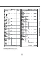
List of Materials
www.zephyronline.com
MODEL: CCA-E30ASX, CCA-E36ASX, CCA-E48ASX
1 - Hood
%DIÀH)LOWHUVIRU´PRGHO
+DORJHQ/LJKWVIRU´PRGHO
´URXQGWRSPRXQWLQJSODWH
6ROLGWRSPRXQWLQJSODWH
5HFWDQJXODUVWDUWLQJFROODU
5RXQGWRUHFWDQJXODUDGDSWHU
%ORZHUEUDFNHWV
´URXQGWRSPRXQWLQJSODWH
([WHUQDOZLULQJKDUQHVV
+DUGZDUHSDFNHW
Cache Hardware
3DFNHW&RQWHQWV
0´[
0´[
0´[
VXFWLRQFXS[
M4 * 8
x 22
]LSWLHKROGHU[
´[´
x4
wire cap x 3
M4 * 6
x4
M3.5 * 10
x4
]LSWLH[
CBI-600A Hardware
M4 * 10
x2
M4 * 16
x4
4
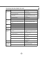
Equivalent number
length x used
=
Duct pieces
Total
Total
3-1/ 4” x 10” 1 Ft.
Rect.,
straight
x(
) =
Ft.
6”- 8” Round 30 Ft.
wall cap
with damper
x(
) =
Ft.
7” Round,
straight
1 Ft.
x(
) =
Ft.
6”- 8” Round, 30 Ft.
roof cap
x(
) =
Ft.
8” Round,
straight
1 Ft.
x(
) =
Ft.
6” round to
1 Ft.
3-1/ 4” x 10”
rect.
transition
x(
) =
Ft.
3-1/ 4” x 10” 15 Ft.
Rect.90 0
elbow
x(
) =
Ft.
x(
) =
Ft.
3-1/ 4” x 10” 9 Ft.
Rect.45 0
elbow
x(
) =
Ft.
6” round to
16 Ft.
3-1/ 4” x 10”
rect.
transition
90 0 elbow
7” or 8”
Round,
90 0 elbow
15 Ft.
x(
) =
Ft.
3-1/ 4” x 10” 24 Ft.
Rect.90 0
flat elbow
x(
7” or 8”
Round,
45 0 elbow
9 Ft.
x(
) =
Ft.
3-1/ 4” x 10” 30 Ft.
Rect.
wall cap
with damper
x(
7” or 8”
30 Ft.
Round
wall cap
with damper
x(
) =
Ft.
3-1/ 4” x 10” 5 Ft.
Rect.to
6” round
transition
x(
) =
Ft.
7” or 8”
Round,
roof cap
x(
) =
Ft.
3-1/ 4” x 10” 15 Ft.
Rect.to
6” round
transition
90 0 elbow
x(
) =
Ft.
7” round to
8 Ft.
3 1/ 4” x 10”
rect.
transition
x(
) =
Ft.
) =
Ft.
15 Ft.
x(
) =
Ft.
7” round to
15 Ft.
3-1/ 4” x 10”
rect.
transition
90 0 elbow
x(
6” Round,
90 0 elbow
6” Round,
45 0 elbow
9 Ft.
x(
) =
Ft.
Subtotal column 2 =
Ft.
Subtotal column 1 =
Ft.
Total ductwork
Ft.
) =
) =
Subtotal column 1 =
Ft.
Ft.
Ft.
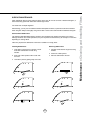
Maximum Duct Length: For satisfactory air movement,
the total duct length of a 3 1/ 4” x 10” rectangular 6”, 7” or 8”
diameter round duct should not exceed 100 equivalent feet.
5
30 Ft.
=
Installation – Ducting Calculation Sheet
Equivalent number
length x used
=
Duct pieces
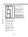
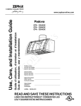
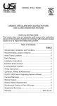
Installation – Mounting Height & Clearance
www.zephyronline.com
Minimum mount height between range top and
KRRGERWWRPVKRXOGEHQROHVVWKDQ´
Maximum mount height should be no higher than
´
It is important to install the hood at the proper
mounting height. Hoods mounted too low could
UHVXOWLQKHDWGDPDJHDQG¿UHKD]DUGZKLOHKRRGV
mounted too high will be hard to reach and will
ORVHLWVSHUIRUPDQFHDQGHI¿FLHQF\
10-23/64"
If available, also refer to range manufacturer’s
height clearance requirements and recommended
hood mounting height above range.
Min 24"-Max 32"
96"
Vertical:
´URXQGPLQLPXPLQWHUQDOEORZHU
´WR´URXQGPLQLPXPH[WHUQDOEORZHU
36"
Horizontal:
´[´PLQLPXPLQWHUQDOEORZHU
No horizontal option available for external blower
DUCTING
$PLQLPXPRI´URXQGRU´[´UHFWDQJXODU
duct work must be used to maintain maximum air
ÀRZHI¿FLHQF\ZLWKWKHFIPLQWHUQDOEORZHU
$PLQLPXPRI´WR´URXQGGXFWZRUNPXVWEH
used with the 1000 cfm external blower.
Always use rigid type metal ducts only. Flexible
GXFWVFRXOGUHVWULFWDLUÀRZE\XSWR
Use calculation (on page 5) to compute total
available duct run when using elbows, transitions
and caps.
ALWAYS, when possible, reduce the number or
transitions and turns. If long duct run is required,
LQFUHDVHGXFWVL]HIURP´WRRU´,IDUHGXFHULV
used, install a long reducer instead of a pancake
reducer. Reduce duct size as far away from
opening as possible.
If turns or transitions are required; install as far
away from opening and as far apart, between 2,
as possible.
6
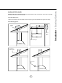
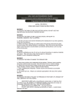
NEVER exhaust air or terminate duct work into spaces between walls, crawl spaces, ceiling, attics or garages.
All exhaust must be ducted to the outside.
Use metal ductwork only.
)DVWHQDOOFRQQHFWLRQVZLWKVKHHWPHWDOVFUHZVDQGWDSHDOOMRLQWVZLWKFHUWL¿HG6LOYHU7DSHRU'XFW7DSH
Some Ducting Options
External
Blower
External
Blower
Soffit or crawl space
Roof Pitch w/
Flashing & Cap
Rear Ducting
7
Installation – Ducting Options
WARNING FIRE HAZARD
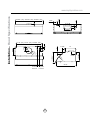
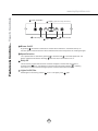
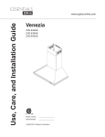
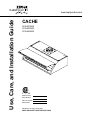
2-3/4”
4-3/16”
1-1/8”
2”
1-1/4”
29-61/64” - (30“), 35-61/64” - (36“), 47-29/32” - (48”)
9-29/32”
27-7/8” - (30“), 33-7/8” - (36“), 45-53/64 - (48”)
2-3/4”
3-19/32”
2”
12”
2”
5-5/32”
4-3/16”
5-5/32”
R2
0”
22-1/8”
ext. blower
knock-out
AC power
knock-out
8
10-23/64”
57- 7/8”
7/
8” or
11-31/32”
8-5/8”
Installation – +RRG6SHFL¿FDWLRQV
www.zephyronline.com
WARNING
$OO(OHFWULFDOZRUNPXVWE\SHUIRUPHGE\TXDOL¿HGHOHFWULFLDQRUSHUVRQZLWKVLPLODUWHFKQLFDONQRZ
how and background.
For personal safety, remove house fuse or open circuit breaker before beginning installation. Do not use
extension cord or adapter plug with this appliance.
Follow national electrical codes or prevailing local codes and ordinances.
Electrical Supply:
This appliance requires a 120V 60Hz electrical supply, and connected to an individual, properly grounded
branch circuit, protected by a 15 or 20 ampere circuit breaker or time delay fuse. Wiring must be 2 wire w/
ground. Please also refer Electrical Diagram labeled on product.
Cable Lock:
A cable locking connector (not supplied) might also be required by local codes. Check with local requirements
and codes, purchase and install appropriate connector if necessary.
Cable Lock
9
Installation – Preparing the Electrical Wires
ELECTRICAL
Installation – Internal Blower (Vertical Ducting)
www.zephyronline.com
INTERNAL BLOWER PREPARATION – VERTICAL DUCTING
1. Attach capacitor box to inside of hood using two
M4*10 screws included with internal blower.
2. Attach green ground wire to ground screw on
hood.
3. Connect 6 pin male connector from capacitor box
to 6 pin female connector on control board box.
3ODFH´URXQGPRXQWLQJSODWHRQWRSRIKRRG
and secure using eight M4*8 screws.
5. Install internal blower into hood.
6. Secure internal blower to hood using four
M4*16 screws included with internal blower.
10
Installation – Internal Blower (Vertical Ducting)
7. Connect 9 pin male connector from blower to 9
pin female connector on capacitor box.
11
Installation – Internal Blower (Horizontal Ducting)
www.zephyronline.com
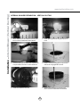
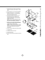
INTERNAL BLOWER PREPARATION – HORIZONTAL DUCTING
1. Attach capacitor box to inside of hood using two
M4*10 screws included with internal blower.
2. Attach green ground wire to ground screw on
hood.
3. Connect 6 pin male connector from capacitor
box to 6 pin female connector on control board
box.
4. Place solid mounting plate on top of hood and
secure using eight M4*8 screws.
5. Remove rectangular cap from back of hood.
Place six M4*8 screws aside for later use.
6. Attach blower brackets to blower as shown above
using two M3.5*10 screws for each bracket.
There are two brackets total, one for each side of
WKHEORZHU127('ULOOHGÀDQJHRIERWKEORZHU
brackets faces away from the blower casing.
12
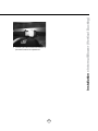
8. Install blower with round to rectangular adapter
into hood.
9. Mount blower brackets to hood using two
´´VFUHZVIRUHDFKEUDFNHW6FUHZV
are included with internal blower.
10. Install rectangular starting collar to back of hood
using six M4*8 screws recently removed from
rectangular cap (three screws on each side).
Install four additional M4*8 screws in the top
and bottom middle of rectangular starting
FROODU&KHFNDQGYHULI\LQQHUDGDSWHULV¿UPO\
secured.
11. Connect 9 pin male connector from blower to 9
pin female connector on control board box.
13
Installation – Internal Blower (Horizontal Ducting)
7. Place blower over round to rectangular adapter
as shown above.
Installation – External Blower Preparation
www.zephyronline.com
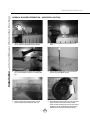
EXTERNAL BLOWER PREPARATION
3ODFH´URXQGPRXQWLQJSODWHRQWRSRIKRRG
and secure using eight M4*8 screws.
2. Install threaded cable lock and external
blower wiring through the knockout next to
the electrical wiring knockout.
3. Place cap over threaded cable lock and secure
by turning cap clockwise. NOTE: Due to the
size of the cap, it may be easier to install it
after the hood has been mounted.
4. Connect 6 pin male connector from external
blower wiring to 6 pin female connector on
control board box. Attach green ground wire
from external wiring to ground screw on hood.
NOTE: For instructions on mounting the external blower please refer to the CBE-1000 external blower manual
included in the external blower packaging or on our website. www.zephyronline.com
14
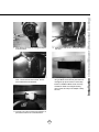
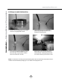
%HJLQLQVWDOODWLRQE\UHPRYLQJWKHEDIÀH¿OWHUV
5. Duct
opening
cutout
5HLQIRUFHFDELQHWZLWK´[´ZRRGVWULSVLI
additional strengthening is required. Must be
placed inside frameless cabinets.
4. Temporarily position the range hood in the
desired mounting location. Measure and
mark the mounting holes, duct and electrical
locations with a pencil.
NOTE:,IXVLQJDQLQWHUQDOEORZHUD´URXQG
duct opening is necessary. If using an external
EORZHUDQ´URXQGRSHQLQJLVQHFHVVDU\
duct/silver
tape
3. Add 1x2
wood strips
5. Drill/cut out the required openings for duct and
electrical access; make sure the duct opening
is large enough to apply duct tape.
NOTE: If installing an external blower, cut out a
PLQLPXP´RSHQLQJIRUWKHH[WHUQDOEORZHU
wires to pass through. Refer to page 8 for
VSHFL¿FDWLRQV
6. Fasten hood onto cabinet with screws provided.
2. Baffle
filters
7. Install electrical.
8. Install duct work and duct tape.
5HLQVWDOOEDIÀH¿OWHUV
10. Power up hood and check for leaks around duct
tape.
15
Installation – Mounting the Range Hood
1. Select preferred duct location (internal blower vertical or horizontal, external blower - vertical
only).
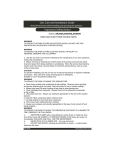
Features & Controls – Touch Controls
www.zephyronline.com
4 Lights On/Off/Dim
3 5 Min Delay Off
5 Display
(Speed level, Delay Off Indicator)
1 Blower On/Off
2 Adjust 3 Speed Levels
1 Blower On/Off
By pressing
, the blower is switched On and Off. When switched on, the blower starts up on
the same speed it was turned off at. When switched off the entire hood powers off, including the lights.
2 Speed Selection
The 3 speed levels are selected by pressing
to decrease and
to increase speed level. The
display indicates level selected. Pressing
when the hood is off will also turn it on.
3 Delay Off
This is used for programmed shut down of blower and lights 5 minutes after the function is
activated. Press
once, a dot displays in the lower right hand side of display
indicating
the function is on. The hood will change to speed 1 and shut down after 5 minutes.
4 Lights On/Off/ Dim
Switch lights On and Off by pressing
once. To dim lights, press
16
again.
Clean periodically with hot soapy water and clean cotton cloth. Do not use corrosive or abrasive detergent, or
steel wool/scoring pads which will scratch and damage surface.
For heavier soil use liquid degreaser.
After cleaning, you may use non-abrasive stainless steel polish/ cleaners, to polish and buff out the stainless
OXVWHUDQGJUDLQ$OZD\VVFUXEOLJKWO\XVLQJDPLFUR¿EHURUFOHDQFRWWRQFORWKDQGZLWKWKHVWDLQOHVVVWHHOJUDLQ
6WDLQOHVV6WHHO%DIÀH)LOWHUV
7KHVWDLQOHVVVWHHOEDIÀH¿OWHUV¿WWHGE\WKHIDFWRU\DUHLQWHQGHGWRWUDSUHVLGXHDQGJUHDVHIURPFRRNLQJ
$OWKRXJKWKH¿OWHUVQHYHUQHHGUHSODFHPHQWWKH\DUHUHTXLUHGWREHFOHDQHGHYHU\GD\VRUPRUHRIWHQ
depending on cooking habits.
Filters may be placed in dishwasher at low heat or soaked in hot soapy water.
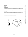
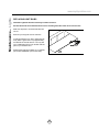
,QVWDOOLQJ%DIÀH)LOWHUV
5HPRYLQJ%DIÀH)LOWHUV
,QVHUW¿OWHULQPHWDOJURRYHRQERWWRPRIKRRG
3XVK¿OWHUWRZDUGVEDFNRIKRRGXVLQJ
handles.
3XOO¿OWHUWRZDUGEDFNRIUDQJHKRRGXVLQJ
handles.
3LYRWIURQWRI¿OWHUXSZDUG
3LYRWIURQWRI¿OWHUXSZDUGXQWLOLWLVÀXVKZLWK
the hood.
3. Remove downwards to the rear.
/RFN¿OWHULQSODFHE\SXOOLQJDZD\IURPKRRG
1
1
2
2
3
3
17
Maintenance – Cleaning and Installing Filters
SURFACE MAINTENANCE:
Maintenance – Lights
www.zephyronline.com
REPLACING LIGHT BULBS
CAUTION: Light bulb becomes extremely hot when turned on.
DO NOT touch bulb until switched off and cooled. Touching hot bulbs could cause serious burns.
Make sure all power is turned off and bulbs are
not hot.
Remove by turning bulb counter clockwise.
,IEXOEVDUHGLI¿FXOWWRWXUQGXHWRSURORQJHGXVH
¿UPO\DWWDFKDJODVVVXFWLRQFXSDSSUR[LPDWHO\
the diameter of the bulb and turn. You may also
use a rubber/latex glove to grip the bulb with the
palm of your hand and turn.
Replacement bulbs are available on our website,
part number Z0B0020S. (GU10 120V 50W.)
18
Issue
Cause
What to do
After installation,
the unit doesn’t
work.
1. The power source is not turned ON.
1. Make sure the circuit breaker and the unit’s
power is ON.
2. The power line and the cable locking connector
is not connecting properly.
2. Check the power connection with the unit is
connected properly.
3. The switch board and control board wirings are
disconnected.
3. Make sure the wirings between the switch
board and control board are connected
properly.
4. Wire harness from external or internal blower
might be disconnected.
4. Make sure the wires are connected to the
control board box
5. The switch board or control board is defective.
5. Change the switch board or control board.
Light works,
but motor is not
turning.
1. The motor is defective, possibly seized.
1. Change the motor.
2. The thermally protected system detects if the
motor is too hot to operate and shuts the motor
down.
2. The motor will function properly after the
thermally protected system cool down.
3. Damaged capacitor.
3. Change the capacitor.
The unit is
vibrating.
1. The motor is not secure in place.
1. Tighten the motor in place.
2. Damaged blower wheel/makes noise.
2. Change the motor.
3. The hood is not secured in place.
3. Check the installation of the hood.
The motor is
working, but the
lights are not.
1. Defective halogen bulb.
1. Change the halogen bulb.
2. The light bulb is loose.
2. Tighten the light bulb.
The hood is
not venting out
properly.
1. The hood might be hanging to high from the
cook top.
1. Adjust the distance between the cook top and
WKHERWWRPRIWKHKRRGZLWKLQ´DQG´
range.
2. The wind from the opened windows or opened
doors in the surrounding area are affecting the
ventilation of the hood.
2. Close all the windows and doors to eliminate
WKHRXWVLGHZLQGÀRZ
3. Blocking in the duct opening or ductwork.
3. Remove all the blocking from the duct work or
duct opening.
4. There are too many turns within the ducting.
4. Limit number of turns and/or increase duct
size.
5. Using the wrong size of ducting.
&KDQJHWKHGXFWLQJWRDWOHDVW´RUKLJKHU
IRUWKHLQWHUQDOEORZHUDQG´RUKLJKHUIRUWKH
external blower.
Filter is vibrating.
%DIÀH¿OWHULVORRVH
5HPRYH¿OWHUDQGUHLQVWDOOLWRUFKDQJHWKH
EDIÀH¿OWHU
After hood has
been installed
for a period of
time, it stopped
working.
1. Control board needs to be reset.
1. Turn circuit breaker which controls the hood
off for at least 15 minutes. Turn it back on and
WKLVVKRXOG¿[WKHSUREOHP
2. Defective control board.
2. Replace control board.
19
Troubleshooting
TROUBLESHOOTING PROCEDURES FOR CACHE
Warranty
www.zephyronline.com
TO OBTAIN SERVICE UNDER WARRANTY:
or any Service Related Questions, please call:
1-888-880-8368
Staple your receipt here.
Proof of the original purchase
date is needed to obtain service
under the warranty.
TO OBTAIN SERVICE UNDER WARRANTY: You must present proof of original purchase date.
Please keep a copy of your dated proof of purchase (sales slip) in order to obtain service under warranty.
One Year Service Repair Warranty:
For one year from date of original purchase, we will provide free of charge, service labor to repair any failed parts or
components due to manufacturing defects.
Two Years Parts Warranty:
For two years from date of original purchase, we will provide free of charge, nonconsumable replacement parts or
components that failed due to manufacturing defects. Consumable parts not covered by this warranty include: Light Bulbs,
Metal and Carbon Filters.
Who is Covered:
This warranty is extended to the original purchaser for products purchased for ordinary home use in the 48 mainland
states, Hawaii and Washington D.C. In Canada and Alaska, this warranty is Limited. There might be costs associated with
shipping the products to our designated service locations or you might need to pay service technician’s travel costs, to
have the appliance repaired in-home.
This Warranty will be Voided when:
Product damaged through negligence, misuse, abuse, accident. Improper installation and failure to follow installation
instructions. When product is used commercially or other than its intended purpose. Damaged because of improper
FRQQHFWLRQZLWKHTXLSPHQWRIRWKHUPDQXIDFWXUHUV5HSDLUHGRUPRGL¿HGE\DQ\RQHRWKHUWKDQ=HSK\U¶V$XWKRUL]HG$JHQWV
What is Not Covered:
&RQVXPDEOHSDUWVVXFKDVOLJKWEXOEV¿OWHUVDQGIXVHV6HUYLFHVRXWVLGHRIVHUYLFHDUHDDQGWKHODERUFRVWLQFXUUHGLQ
connection with the removal, shipping and reinstallation cost, nor does it cover any other contingent expenses. The natural
ZHDURI¿QLVKDQGZHDUGXHWRLPSURSHUPDLQWHQDQFHXVHRIFRUURVLYHDQGDEUDVLYHFOHDQLQJSURGXFWVSDGVDQGRYHQ
cleaner products. Chips, dents or cracks due to abuse, misuse, freight damage, or improper installation. Service trips to
\RXUKRPHWRWHDFK\RXKRZWRXVHWKHSURGXFW'DPDJHRISURGXFWFDXVHGE\DFFLGHQW¿UHÀRRGVRUDFWRI*RG
This warranty is valid in the United States and Canada. It is non-transferable and applies only to the original purchaser
and does not extend to subsequent owners of this product. Any applicable implied waranties, including the warranty of
merchantability, are limited in duration to a period of express warranty as provided herein beginning with the date of original
purchase at retail and, no warranties, whether express or implied, shall apply to this product thereafter.
Have your product proof of purchase with date ready for warranty issues.
Or write to:
Zephyr Corporation
Service and Warranty Department
395 Mendell Street
San Francisco, CA 94124