1
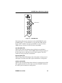
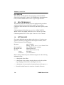
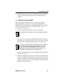
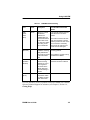
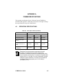
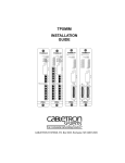
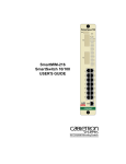
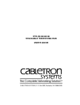
FOMIM-32/36/38 FIBER OPTIC MEDIA INTERFACE MODULE USER’S GUIDE notice Page i Monday, July 8, 1996 4:38 PM NOTICE Cabletron Systems reserves the right to make changes in specifications and other information contained in this document without prior notice. The reader should in all cases consult Cabletron Systems to determine whether any such changes have been made. The hardware, firmware, or software described in this manual is subject to change without notice. IN NO EVENT SHALL CABLETRON SYSTEMS BE LIABLE FOR ANY INCIDENTAL, INDIRECT, SPECIAL, OR CONSEQUENTIAL DAMAGES WHATSOEVER (INCLUDING BUT NOT LIMITED TO LOST PROFITS) ARISING OUT OF OR RELATED TO THIS MANUAL OR THE INFORMATION CONTAINED IN IT, EVEN IF CABLETRON SYSTEMS HAS BEEN ADVISED OF, KNOWN, OR SHOULD HAVE KNOWN, THE POSSIBILITY OF SUCH DAMAGES. Copyright 1996 by Cabletron Systems, Inc., P.O. Box 5005, Rochester, NH 03866-5005 All Rights Reserved Printed in the United States of America Order Number: 9030524-01 July 1996 SPECTRUM, LANVIEW, MicroMMAC, and BRIM are registered trademarks and Element Manager, EPIM, EPIM-A, EPIM-F1, EPIM-F2, EPIM-F3, EPIM-T, EPIM-X, FOMIM, FOT-F, FOT-F3, HubSTACK, SEH, SEHI, and TMS-3 are trademarks of Cabletron Systems, Inc. All other product names mentioned in this manual may be trademarks or registered trademarks of their respective companies. FCC NOTICE This device complies with Part 15 of the FCC rules. Operation is subject to the following two conditions: (1) this device may not cause harmful interference, and (2) this device must accept any interference received, including interference that may cause undesired operation. NOTE: This equipment has been tested and found to comply with the limits for a Class A digital device, pursuant to Part 15 of the FCC rules. These limits are designed to provide reasonable protection against harmful interference when the equipment is operated in a commercial environment. This equipment uses, generates, and can radiate radio frequency energy and if not installed in accordance with the operator’s manual, may cause harmful interference to radio communications. Operation of this equipment in a residential area is likely to cause interference in which case the user will be required to correct the interference at his own expense. WARNING: Changes or modifications made to this device which are not expressly approved by the party responsible for compliance could void the user’s authority to operate the equipment. Printed on Recycled Paper FOMIM User’s Guide This document was created with FrameMaker 4.0.2 i notice Page ii Monday, July 8, 1996 4:38 PM Notice DOC NOTICE This digital apparatus does not exceed the Class A limits for radio noise emissions from digital apparatus set out in the Radio Interference Regulations of the Canadian Department of Communications. Le présent appareil numérique n’émet pas de bruits radioélectriques dépassant les limites applicables aux appareils numériques de la class A prescrites dans le Règlement sur le brouillage radioélectrique édicté par le ministère des Communications du Canada. VCCI NOTICE This equipment is in the 1st Class Category (information equipment to be used in commercial and/or industrial areas) and conforms to the standards set by the Voluntary Control Council for Interference by Information Technology Equipment (VCCI) aimed at preventing radio interference in commercial and/or industrial areas. Consequently, when used in a residential area or in an adjacent area thereto, radio interference may be caused to radios and TV receivers, etc. Read the instructions for correct handling. CABLETRON SYSTEMS, INC. PROGRAM LICENSE AGREEMENT IMPORTANT: Before utilizing this product, carefully read this License Agreement. This document is an agreement between you, the end user, and Cabletron Systems, Inc. (“Cabletron”) that sets forth your rights and obligations with respect to the Cabletron software program (the “Program”) contained in this package. The Program may be contained in firmware, chips or other media. BY UTILIZING THE ENCLOSED PRODUCT, YOU ARE AGREEING TO BECOME BOUND BY THE TERMS OF THIS AGREEMENT, WHICH INCLUDES THE LICENSE AND THE LIMITATION OF WARRANTY AND DISCLAIMER OF LIABILITY. IF YOU DO NOT AGREE TO THE TERMS OF THIS AGREEMENT, PROMPTLY RETURN THE UNUSED PRODUCT TO THE PLACE OF PURCHASE FOR A FULL REFUND. ii FOMIM User’s Guide notice Page iii Monday, July 8, 1996 4:38 PM Notice CABLETRON SOFTWARE PROGRAM LICENSE 1. LICENSE. You have the right to use only the one (1) copy of the Program provided in this package subject to the terms and conditions of this License Agreement. You may not copy, reproduce or transmit any part of the Program except as permitted by the Copyright Act of the United States or as authorized in writing by Cabletron. 2. OTHER RESTRICTIONS. You may not reverse engineer, decompile, or disassemble the Program. 3. APPLICABLE LAW. This License Agreement shall be interpreted and governed under the laws and in the state and federal courts of New Hampshire. You accept the personal jurisdiction and venue of the New Hampshire courts. EXCLUSION OF WARRANTY AND DISCLAIMER OF LIABILITY 1. EXCLUSION OF WARRANTY. Except as may be specifically provided by Cabletron in writing, Cabletron makes no warranty, expressed or implied, concerning the Program (including its documentation and media). CABLETRON DISCLAIMS ALL WARRANTIES, OTHER THAN THOSE SUPPLIED TO YOU BY CABLETRON IN WRITING, EITHER EXPRESSED OR IMPLIED, INCLUDING BUT NOT LIMITED TO IMPLIED WARRANTIES OF MERCHANTABILITY AND FITNESS FOR A PARTICULAR PURPOSE, WITH RESPECT TO THE PROGRAM, THE ACCOMPANYING WRITTEN MATERIALS, AND ANY ACCOMPANYING HARDWARE. 2. NO LIABILITY FOR CONSEQUENTIAL DAMAGES. IN NO EVENT SHALL CABLETRON OR ITS SUPPLIERS BE LIABLE FOR ANY DAMAGES WHATSOEVER (INCLUDING, WITHOUT LIMITATION, DAMAGES FOR LOSS OF BUSINESS, PROFITS, BUSINESS INTERRUPTION, LOSS OF BUSINESS INFORMATION, SPECIAL, INCIDENTAL, CONSEQUENTIAL, OR RELIANCE DAMAGES, OR OTHER LOSS) ARISING OUT OF THE USE OR INABILITY TO USE THIS CABLETRON PRODUCT, EVEN IF CABLETRON HAS BEEN ADVISED OF THE POSSIBILITY OF SUCH DAMAGES. BECAUSE SOME STATES DO NOT ALLOW THE EXCLUSION OR LIMITATION OF LIABILITY FOR CONSEQUENTIAL OR INCIDENTAL DAMAGES, OR ON THE DURATION OR LIMITATION OF IMPLIED WARRANTIES, IN SOME INSTANCES THE ABOVE LIMITATIONS AND EXCLUSIONS MAY NOT APPLY TO YOU. UNITED STATES GOVERNMENT RESTRICTED RIGHTS The enclosed product (a) was developed solely at private expense; (b) contains “restricted computer software” submitted with restricted rights in accordance with Section 52227-19 (a) through (d) of the Commercial Computer Software - Restricted Rights Clause and its successors, and (c) in all respects is proprietary data belonging to Cabletron and/or its suppliers. For Department of Defense units, the product is licensed with “Restricted Rights” as defined in the DoD Supplement to the Federal Acquisition Regulations, Section 52.227-7013 (c) (1) (ii) and its successors, and use, duplication, disclosure by the Government is subject to restrictions as set forth in subparagraph (c) (1) (ii) of the Rights in Technical Data and Computer Software clause at 252.227-7013. Cabletron Systems, Inc., 35 Industrial Way, Rochester, New Hampshire 03867-0505. FOMIM User’s Guide iii notice Page iv Monday, July 8, 1996 4:38 PM Notice DECLARATION OF CONFORMITY Application of Council Directive(s): Manufacturer’s Name: Manufacturer’s Address: European Representative Name: European Representative Address: Conformance to Directive(s)/Product Standards: Equipment Type/Environment: 89/336/EEC 73/23/EEC Cabletron Systems, Inc. 35 Industrial Way PO Box 5005 Rochester, NH 03867 Mr. J. Solari Cabletron Systems Limited Nexus House, Newbury Business Park London Road, Newbury Berkshire RG13 2PZ, England EC Directive 89/336/EEC EC Directive 73/23/EEC EN 55022 EN 50082-1 EN 60950 Networking Equipment, for use in a Commercial or Light Industrial Environment. We the undersigned, hereby declare that the equipment packaged with this notice conforms to the above directives. Manufacturer Legal Representative in Europe Mr. Richard Michaud ___________________________________ Full Name Mr. J. Solari ___________________________________ Full Name Manager of Engineering Services ___________________________________ Title Managing Director - E.M.E.A. ___________________________________ Title Rochester, NH, USA ___________________________________ Location Newbury, Berkshire, England ___________________________________ Location iv FOMIM User’s Guide CONTENTS CHAPTER 1 INTRODUCTION 1.1 Using This Manual....................................................................... 1-1 1.2 Document Conventions ............................................................... 1-3 1.3 Fiber Optic Media Interface Modules........................................... 1-3 1.3.1 Distance and Cable Type ............................................... 1-3 1.3.2 Multi Media Access Centers ........................................... 1-4 1.4 LANVIEW Status Monitoring System .......................................... 1-4 1.5 Related Manuals.......................................................................... 1-6 1.6 Getting Help................................................................................. 1-6 CHAPTER 2 NETWORK REQUIREMENTS AND INSTALLATION 2.1 Network Cable Requirements...................................................... 2-1 2.1.1 Fiber Optic Network Design Guidelines .......................... 2-1 2.2 Unpacking the FOMIM................................................................. 2-2 2.3 Installing the FOMIM into the MMAC........................................... 2-3 2.4 Connecting Fiber Optic Cabling to the FOMIM............................ 2-4 CHAPTER 3 TESTING AND TROUBLESHOOTING 3.1 Installation Test ........................................................................... 3-1 3.1.1 Testing the Fiber Optic Link Segment ............................ 3-1 3.1.2 Link Test ......................................................................... 3-2 3.2 Pre-Installation Test..................................................................... 3-3 3.3 Using LANVIEW .......................................................................... 3-4 APPENDIX A FOMIM SPECIFICATIONS INDEX FOMIM User’s Guide v Contents vi FOMIM User’s Guide CHAPTER 1 INTRODUCTION Welcome to the Cabletron Systems FOMIM-32/36/38 Fiber Optic Media Interface Module User’s Guide. We have designed this manual to serve as a simple installation and reference guide for the FOMIM, and to explain the capabilities and special features of the module. Before using the FOMIM, you need to carefully read through this manual to gain a full understanding of the FOMIM and its capabilities. Cabletron Systems offers three versions of 1300 nm single mode Fiber Optic Media Interface Modules: • FOMIM-32 providing 12 links with ST type connectors • FOMIM-36 providing 6 links with ST type connectors • FOMIM-38 providing 18 links with ST type connectors 1.1 USING THIS MANUAL Chapter 1, Introduction, discusses the capabilities and special features of the Cabletron Systems FOMIMs (Figure 1-1). This chapter also includes a list of related manuals. Chapter 2, Network Requirements and Installation, contains a list of network requirements that must be met before you install the FOMIM and instructions for installing the FOMIM into the MMAC chassis. Chapter 3, Testing and Troubleshooting, provides procedures for testing and troubleshooting the installation of the FOMIM. Instructions for using LANVIEW, Cabletron Systems built-in visual diagnostic and status monitoring system, are also included. Appendix A, FOMIM Specifications, contains operational specifications and environmental requirements for the FOMIM. FOMIM User’s Guide 1-1 Chapter 1: Introduction Figure 1-1 The FOMIMs It is assumed that you have a general working knowledge of Ethernet or IEEE 802.3 type data communications networks and their physical layer components. 1-2 FOMIM User’s Guide Document Conventions 1.2 DOCUMENT CONVENTIONS The following conventions are used throughout this document: NOTE ! Note symbol. Calls the reader’s attention to any item of information that may be of special importance. Caution symbol. Contains information essential to avoid damage to the equipment. CAUT ION Warning symbol. Warns against an action that could result in equipment damage, personal injury or death. 1.3 FIBER OPTIC MEDIA INTERFACE MODULES Cabletron Systems Fiber Optic Media Interface Modules provide a choice of six, twelve, or eighteen ports with ST connectors. NOTE 1.3.1 The FOMIM-32/36/38 use 1300 nm wavelength transmitters and receivers (not the 850 nm specified by FOIRL) and should be used only with the Cabletron Systems Ethernet single mode transceiver, the FOT-F3. Distance and Cable Type The FOMIMs support single mode fiber optic cable for sizes such as 8.3/125 µm, 8.7/125 µm, 9/125 µm, 10/125 µm, and 12/125 µm. The cable distance is dependent on the cable type and the overall system fiber optic budget. If the system budgets and timing constraints are met, then a distance of up to 5 kilometers is possible. You can also use 62.5/125 µm multimode cable with the FOMIM, but due to greater optical loss, signal distance is reduced to 2 km. FOMIM User’s Guide 1-3 Chapter 1: Introduction 1.3.2 Multi Media Access Centers The Cabletron Systems Fiber Optic Media Interface Modules are designed to be installed into the Cabletron Systems Multi Media Access Center (MMAC). The modular design of the MMAC allows the FOMIM to co-exist with other Media Interface Modules (MIMs) to provide a variety of different media connections on any one point. Each packet entering the FOMIM is repeated by the repeater module in the MMAC. Each packet that enters the repeater module is regenerated and retimed, which assures data integrity and maximum data path distance. In addition, the repeater feature ensures fault isolation, because the repeater module automatically segments problem ports from the network. A segmented port automatically reconnects to the network once the port receives a good packet. The repeater module also allows you to access the network management capabilities that enable you to control the FOMIM and its attached segments. For example, information on the number of good packets and collisions that have passed through the FOMIM and each port on the MIM can be gathered. For more information on managing the FOMIM, refer to your specific management module Local Management Guide. 1.4 LANVIEW STATUS MONITORING SYSTEM The FOMIM uses Cabletron Systems built-in visual diagnostic and status monitoring system, LANVIEW. Using LANVIEW, network troubleshooting personnel can quickly scan the LANVIEW LEDs to observe network status, diagnose network problems, and determine which node or segment is faulty (see Figure 1-2). 1-4 FOMIM User’s Guide LANVIEW Status Monitoring System LANVIEW LEDs Figure 1-2 LANVIEW LEDs The following discusses the function of each LANVIEW LED on the FOMIM (Figure 1-2). Note that there is one Link OK (LNK) and one Receive (RCV) LED for each port on the MIM, as well as one Error (ERR) and one Collision (CLN) LED for the entire MIM. Link OK (LNK) LED When lit, this green LED indicates that a link has been established between the receive circuitry of the FOMIM and the transmit circuitry of the fiber optic device at the other end of the link segment. This LED remains lit as long as the link is maintained. Receive (RCV) LED When lit, this yellow LED indicates that a data packet is being received on that port. The flash of the LED is pulse stretched for viewing effect. Collision (CLN) LED When lit, this red LED indicates that a collision is occurring on one of the fiber segments attached to a fiber optic port on the FOMIM. The flash of the LED is pulse stretched for viewing effect. FOMIM User’s Guide 1-5 Chapter 1: Introduction Error (ERR) LED When lit, this red LED indicates the temperature within the MMAC chassis has risen to 40°C or greater. The FOMIM alerts the management board, and the FOMIM in turn receives a signal to light the LED. 1.5 RELATED MANUALS The manuals listed below should be used to supplement the procedures and other technical data provided in this manual. The procedures contained in these manuals will be referenced, rather than repeated, in this manual. Cabletron Systems Multi Media Access Center (MMAC-M3FNB, MMAC-M5FNB, and MMAC-M8FNB) Overview and Set Up Guides. Cabletron Systems FOT-F3 Fiber Optic Transceiver User's Manual. 1.6 GETTING HELP If you need additional support related to this device, or if you have any questions, comments, or suggestions concerning this manual, contact Cabletron Systems Technical Support: By phone By CompuServe By Internet mail By FTP Login Password (603) 332-9400 Monday – Friday; 8 A.M. – 8 P.M. Eastern Time GO CTRON from any ! prompt [email protected] ctron.com (134.141.197.25) anonymous your email address Before calling Cabletron Systems Technical Support, have the following information ready: • A description of the failure • A description of any action(s) already taken to resolve the problem (e.g., changing mode switches, rebooting the unit, etc.) • A description of your network environment (layout, cable type, etc.) • Network load and frame size at the time of trouble (if known) 1-6 FOMIM User’s Guide Getting Help • The serial and revision numbers of all Cabletron Systems products in the network • The device history (i.e., have you returned the device before, is this a recurring problem, etc.) • Any previous Return Material Authorization (RMA) numbers FOMIM User’s Guide 1-7 Chapter 1: Introduction 1-8 FOMIM User’s Guide CHAPTER 2 NETWORK REQUIREMENTS AND INSTALLATION This chapter begins with network design guidelines in Section 2.1, Network Cable Requirements, that must be met before installing the module in a network. It then provides instructions for installing the Cabletron Systems Fiber Optic Media Interface Module into the MMAC family of modular hubs. 2.1 NETWORK CABLE REQUIREMENTS When connecting fiber optic segments to the FOMIM, you must follow the network guidelines listed below. Failure to do so may result in unsatisfactory network performance. 2.1.1 Fiber Optic Network Design Guidelines • The fiber optic link segment should consist of 8/125 – 12/125 µm single mode fiber optic cabling. You can also use 62.5/125 µm multimode cable with the FOMIM. However, optical loss will be greater with multimode cable and distances will be limited to 2 km. • The fiber optic cable must be tested with a fiber optic attenuation test set that is adjusted for a 1300 nm wave length. This test verifies that the signal loss in a cable is within an acceptable level of 9.0 dB or less for any given single mode fiber optic link. • When determining the maximum fiber optic cable length, the fiber optic budget (total loss of 9.0 dB or less between stations) and total network propagation delay should be calculated and considered before fiber runs are incorporated in any network. Fiber optic budget is the combination of the optical loss due to the fiber optic cable, in-line splices, and fiber optic connectors (the loss for each splice and connector is typically 1 dB or less). FOMIM User’s Guide 2-1 Chapter 2: Network Requirements and Installation Propagation delay is the amount of time it takes a packet to travel from the sending device to the receiving device. Total propagation delay allowed for the entire network is 25.6 µs. If the total propagation delay between any two nodes on the network exceeds 25.6 µs, then bridges should be used. • When using single mode fiber optic cable, segment lengths up to 5 km are possible if system budgets are met. 2.2 UNPACKING THE FOMIM Unpack the module as follows: ! The module is very sensitive to static discharge. Observe all electrostatic precautions while handling the FOMIM. CAUT ION 1. Remove the shipping material covering the FOMIM in the shipping box. 2. Verify the contents of the shipping box. The box, as packed should contain one FOMIM, one grounding strap, and one user’s guide. 3. Carefully remove the FOMIM from the shipping box. Leave the module in its conductive bag until you are ready to install it. Save the shipping box and materials in the event the unit has to be reshipped. 4. Visually inspect the module within the nonconductive bag. If you see any damage, contact Cabletron Systems Technical Support immediately. 2-2 FOMIM User’s Guide Installing the FOMIM into the MMAC 2.3 INSTALLING THE FOMIM INTO THE MMAC You can easily install the FOMIM into a Multi Media Access Center with a Flexible Network Bus (MMAC-FNB). Install the FOMIM into the MMAC as follows: 1. Power down the MMAC hub. 2. Remove any chassis safety bars present on the front of the MMAC hub. 3. Slide the FOMIM (Figure 2-1) into the card cage of the MMAC hub. Be sure that the card is properly aligned in the top and bottom slots of the card cage. NOTE Slot 1 of the MMAC hub is reserved for a management module (e.g., IRM3) only. 4. Firmly press the module connections into the backplane. Do not force the module into place or use the knurled knobs to draw the module into place. 5. Screw in the knurled knobs to secure the module to the MMAC. 6. Reinstall any chassis safety bars that were present on the MMAC. FOMIM MMAC-8FNB Figure 2-1 FOMIM User’s Guide Installing the FOMIM 2-3 Chapter 2: Network Requirements and Installation 2.4 CONNECTING FIBER OPTIC CABLING TO THE FOMIM Each fiber optic link consists of two strands of fiber optic cabling: the transmit (TX) and the receive (RX). The transmit strand from a module port connects to the receive port of a fiber optic Ethernet device at the other end of the segment. The receive strand of the applicable port on the module connects to the transmit port of the fiber optic Ethernet device. Cabletron Systems recommends labeling fiber optic cables to indicate receive and transmit ends. Many cables are prelabeled, providing matching labels or tapes at both ends of each strand of cable. 1. Remove the protective plastic covers from the fiber optic ports on the applicable port on the module, and from the ends of the connectors on each fiber strand. ! CAUT ION Do not touch the ends of the fiber optic strands, and do not let the ends come in contact with dust, dirt, or other contaminants. Contamination of the ends can cause problems in data transmissions. If the ends become contaminated, clean them with denatured alcohol using a soft, clean, lint free cloth. 2. Attach one fiber to the applicable receive port on the module. Insert the ST connector into the port with the alignment slot on the connector clockwise to lock it down. Figure 2-2 ST Connector Insertion 3. Attach the other fiber of the pair to the applicable transmit port on the module. Use the same procedure for insertion of the ST connector. 2-4 FOMIM User’s Guide Connecting Fiber Optic Cabling to the FOMIM 4. At the other end of the fiber optic cable, attach the fiber pair to the transmit and receive ports of the device. If link indicators are present for the fiber optic connection, check that they are ON. If an indicator is present but not ON, that port does not have a valid link. Perform each of the following steps until you reach a resolution of the problem and achieve a link. • Check that the device at the other end of the link is ON. • Verify proper cross-over of the fiber strands. Try swapping the transmit and receive connections at only one end of the link. • Verify that the fiber connection meets the dB loss specifications outlined in Appendix A, FOMIM Specifications. If you are still unable to establish a link, attempt to make the connection between the devices with another fiber optic cable. If this is unsuccessful, contact Cabletron Systems Technical Support. FOMIM User’s Guide 2-5 Chapter 2: Network Requirements and Installation 2-6 FOMIM User’s Guide CHAPTER 3 TESTING AND TROUBLESHOOTING This chapter lists the installation checkout procedures necessary to verify that the segments connected to your FOMIM are operating properly. The chapter concludes with a description of the LANVIEW LEDs and their use in troubleshooting physical layer network problems. 3.1 INSTALLATION TEST This section contains procedures to test the following: • The fiber optic link segment to be attached to the FOMIM • The link between the FOMIM and the device attached to the other end of the fiber optic link segment • The FOMIM itself 3.1.1 Testing the Fiber Optic Link Segment Test the segment being attached to the FOMIM to verify that the cable meets the fiber budget specifications discussed in Appendix A. Using a fiber optic power meter set, test the link segment as follows: ! CAUT ION Do not touch the ends of the fiber optic strands, and do not let the ends come in contact with dust, dirt, or other contaminants. Contamination of the ends can cause problems in data transmissions. If the ends become contaminated, clean them with denatured alcohol using a soft, clean, lint free cloth. 1. Attach a fiber optic jumper to the optical power meter. The meter should be set at 1300 nm. 2. Attach a fiber optic jumper to the optical source unit. If the source unit has multiple settings, it should be set at 1300 nm. 3. Using a barrel connector, connect the jumpers together. 4. Following the instructions for the test set, test the jumpers to get a reference level. Make a note of this reading. FOMIM User’s Guide 3-1 Chapter 3: Testing and Troubleshooting 5. Disconnect the jumpers from the barrel connector. 6. Using the jumper, attach the optical power meter to one end of one strand of the link segment. 7. Using the other jumper, attach the other end of the same strand to the optical source unit. 8. Note the reading on the optical power meter. This is your test level. 9. Subtract the reference level found in Step 4 from the test level to find your dB loss for the fiber optic link segment, i.e., dB loss = Test Level - Reference Level. 10. Verify that the reading on the receive unit falls within the range indicated by the Receive Sensitivity and Maximum Receive Input Power specifications listed in the Fiber Optic Interface section of Appendix A. 11. Repeat Steps 6 through 10 for the other strand in the link segment. If the fiber optic link segment does not meet the specifications, it may be contaminated with dust, dirt, or other contaminants. Try cleaning the connection at each end of the cable with denatured alcohol, using a soft, clean, lint free cloth, then repeat the test. If this does not work, contact Cabletron Systems technical support. 3.1.2 Link Test To verify the physical link between your devices, check the LNK LEDs on your FOMIM and receiving device for the applicable port. If the LEDs are lit, the proper connection has been made. If the LEDs are not lit, perform the following procedure, using a Cabletron Systems FOT-F3 Fiber Optic Transceiver at the other end of the cable. 1. Check that power is being supplied to both the FOMIM in the MMAC chassis and the device at the other end of the link. 2. Reverse the fiber optic cable ends at either the applicable port on the module or at the device. 3. Check if the LEDs are lit. 3-2 FOMIM User’s Guide Pre-Installation Test 4. If the LEDs are not lit, reverse the cable ends back to their original positions, and contact Cabletron Systems Technical Support for assistance. 3.2 PRE-INSTALLATION TEST Before installing the FOMIM in a live network, test the module in a controlled situation to ensure that it is repeating packets. With the FOMIM installed in an MMAC hub with a Repeater module (e.g., IRM3), this test can be performed with two workstations (Figure 3-1) by completing the following steps: 1. Install the FOMIM into an MMAC chassis with an IRM3. The IRM3 must be installed in slot one of the MMAC chassis. NOTE 2. Connect the first workstation to the IRM3 using either the AUI port, (with a transceiver and an AUI cable), or to the fiber optic port, (with fiber optic cable), depending on which is the active repeater port. NOTE The AUI port is the default active repeater port on the IRM3. If you want to test the module using the fiber port, it must be selected through Local Management. Refer to the Local Management section of the IRM3 User’s Guide for more information on selecting the active repeater port. 3. Connect the second workstation to the FOMIM, using the appropriate transceivers and cable. 4. Set the first workstation as the file server and the second as the client (refer to the workstation documentation for setting up the workstations as file server and client). When the workstations are properly set up, proceed to send packets between the workstations and verify that the FOMIM is operating properly. FOMIM User’s Guide 3-3 Chapter 3: Testing and Troubleshooting NOTE A “ping” test will verify that the module is operating properly. However, both server and client workstations must have their own unique IP Addresses. If failures occur, refer to Section 3.3, Using LANVIEW, in this chapter. MMAC-M3FNB with IRM3 File Server Workstation 0494109 Client Workstation Figure 3-1 Pre-Installation Test 3.3 USING LANVIEW The FOMIM uses Cabletron Systems built-in visual diagnostic and status monitoring system called LANVIEW. With LANVIEW, network troubleshooting personnel can quickly scan LEDs to observe network status, or diagnose network problems. Figure 1-2 in Chapter 1 shows the location of the LANVIEW LEDs. 3-4 FOMIM User’s Guide Using LANVIEW Table 3-1 LANVIEW Troubleshooting Error Condition/Recommended Action Led Color Description LNK (Link/ Fiber Port) Green When on, a link is established between the FOMIM Fiber port and the fiber device at the other end of the segment. LED is on as long as the link is maintained. If off, the link between the port and fiber device has been broken. When flashing the FOMIM is receiving data packets from segments connected to the associated port. If off, the FOMIM is not receiving packets. Excessive flashing or on solid indicates excessive collisions. RCV (Receive) Yellow CLN (Collision Present) Red When flashing, a collision is being detected on one or more segments connected to the MMAC. Note that periodic flashing is normal. ERR (Error) Red Remains lit when the temperature within the MMAC chassis rises above 40°C. Check the connectors at each end of the segment to ensure that they are free of dust. Clean the connectors if necessary. Reconnect the segment and check the Link LED again. Check that the module is firmly installed in the MMAC. If you are not able to resolve a problem with your FOMIM, call Cabletron Systems Technical Support for assistance (see Chapter 1, Section 1.6, Getting Help). FOMIM User’s Guide 3-5 Chapter 3: Testing and Troubleshooting 3-6 FOMIM User’s Guide APPENDIX A FOMIM SPECIFICATIONS The operating specifications for the Cabletron Systems FOMIM are included in this Appendix. Cabletron Systems reserves the right to change these specifications at any time without notice. A.1 OPERATING SPECIFICATIONS Table A-1 Fiber Optic Interface (All Ports) Transceiver Built-In Cabletron Systems FOT-F3 Parameter Typical Minimum Maximum Receive Sensitivity -31.0 dBm -36.0 dBm -30.0 dBm Max. Receive Input Power -14.0 dBm Transmitter Power at 25°C Into 8.3/125 µm fiber: -18.0 dBm Output Power Coefficient -0.07 dB/°C NOTE -21.0 dBm -15.0 dBm Transmitter Power decreases as temperatures rise and increases as temperatures fall. Use the Output Power Coefficient to calculate increased or decreased power output for your operating environment. For example, the typical power output at 25° C is -16.4 dBm. For a 4° C temperature increase, multiply the typical coefficient (-0.07 dB) by four and add the result to the typical output power (4°C x -0.07 dB/°C) + (-16.4dBm) = -16.7). FOMIM User’s Guide A-1 Appendix A: FOMIM Specifications Table A-2 Fiber Optic Interface (All Ports) Parameter Typical Minimum Maximum Transmitter Peak Wave Length 1310 nm 1265 nm 1380 nm Spectral Width 95 nm Rise Time 3.0 ns 2.7 ns 5.0 ns Fall Time 2.5 ns 2.2 ns 5.0 ns Duty Cycle 50.1% 49.6% 50.7% Bit Error Rate Better than 10-10 NOTES 125 nm The transmitter power levels given above are Peak Power Levels after optical overshoot. You must use a Peak Power Meter to correctly compare the values given above to those measured on any particular port. If you are measuring power levels with an Average Power Meter, add 3 dBm to the average power measurement to compare the measured average power values to the values listed above (i.e., -33.5 dBm average + 3 dB = -30.5 dBm peak). A.2 ENVIRONMENTAL REQUIREMENTS Operating Temperature: +5° to +40°C (41° to 104°F) Non-operating Temperature: -30° to +80°C (-22° to 176°F) Operating Humidity: 5% to 95% (non-condensing) A-2 FOMIM User’s Guide Agency Approvals A.3 AGENCY APPROVALS Designed in accordance with UL478, UL910, NEC 725-2(b), CSA, IEC, TUV, VDE Class A. Meets FCC Part 15, Class A limits. It is the responsibility of the person who sells the system of which the FOMIM will be a part to ensure that the total system meets allowed limits of conducted and radiated emissions. PHYSICAL PROPERTIES Dimensions: 34.04 D x 29.21 H x 5.08 W cm (13.4 D x 11.5 H x 2.0 W in) Weight: FOMIM-36: 0.57 kg (1.25 lb) FOMIM-32: 0.86 kg (1.90 lb) FOMIM-38: 1.13 kg (2.50 lb) FOMIM User’s Guide A-3 Appendix A: FOMIM Specifications A-4 FOMIM User’s Guide INDEX C S Cable connecting 2-4 distance 1-3 requirements 2-1 CLN LED 1-5 Conventions 1-3 ST connectors 2-5 D T Testing pre-installation 3-3, 3-4 U Using LANVIEW 3-4 Design guidelines 2-1 E ERR LED 1-5 F FOMIM installing 2-3 specifications A-1 unpacking 2-2 H Help 1-6 L LANVIEW location 1-4 troubleshooting 3-5 Link testing 3-1 LNK LED 1-5 M MMAC description 1-3 R RCV LED 1-5 Related manuals 1-5 FOMIM User’s Guide Index-1 Index Index-2 FOMIM User’s Guide