1
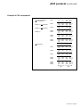
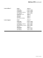
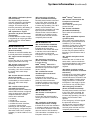
MGETM GalaxyTM 6000
50, 60 Hz
250 - 600 kVA
"GTC link"
communication
interface
User manual
125
0 Hour
kVA120%
100%
50 Min.
100%
80%
50%
6000
AXY
GAL E IQ
SALL
400
kVA
50%
0
Load
protect
ed
Availab
le Backup
Load
0
level
Time
Q5N
Load ent
equipm
Home
Alarms
Q1
QF1
Online
Trend
Statisti
cs
Rectifie
Norma
l AC
r
Q4S
Battery
Inverte
r
Bypass
15:24:3
AC
2 30/05/2
005
Q3BP
Bypass
Output
Set
up
6739389EN/FB -
Page 1
Page 2 - 6739389EN/FB
Contents
Presentation ...................................................................................................... 4
Introduction ................................................................................................................ 4
"GTCZ" and "GT2Z" boards features ......................................................................... 4
Communication settings ........................................................................... 5
JBUS protocol .................................................................................................. 6
Introduction ................................................................................................................ 6
Principle ..................................................................................................................... 7
Synchronizing data exchanges .................................................................................. 7
Description of request and response frames ............................................................. 7
Checking received messages on the slave-side ........................................................ 8
Functions .................................................................................................................... 9
CRC 16 algorithm .................................................................................................... 14
UPS theory of operation .......................................................................... 18
Unitary UPS ............................................................................................................. 18
Parallel connected UPS with "Static Switch" cubicle ............................................... 19
UPS without Mains 2 ................................................................................................ 19
Unitary UPS ..................................................................................................... 21
Block diagram .......................................................................................................... 21
Measured quantities ................................................................................................. 21
Main status bits ........................................................................................................ 22
Operating modes ..................................................................................................... 22
Parallel connected UPS ........................................................................... 24
Block diagram .......................................................................................................... 24
Measured quantities ................................................................................................. 24
Main status bits of system operations ...................................................................... 25
Operating modes ..................................................................................................... 25
Static switch cubicle .................................................................................. 26
Block diagram .......................................................................................................... 26
Measured quantities ................................................................................................. 26
Main status bits of system operations ...................................................................... 27
Operating modes ..................................................................................................... 27
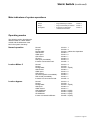
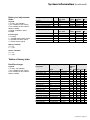
System information .................................................................................... 28
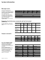
Message format ....................................................................................................... 28
Example of read data ............................................................................................... 28
Sample commands .................................................................................................. 28
List of variable fields ................................................................................................ 28
General definitions ................................................................................................... 29
Signaling field ........................................................................................................... 29
Tables measured data .............................................................................................. 29
Tables of binary data ................................................................................................ 31
Table of control devices ........................................................................................... 33
Telemonitoring information ....................................................................................... 33
Glossary of information descriptors ......................................................................... 34
Glossary of telemonitoring information descriptors .................................................. 37
All MGETM GalaxyTM 6000 products are protected by patents. They implement original APC by Schneider Electric technology
not available to other manufacturers.
This document may be copied only with the written consent of APC by Schneider Electric.
Authorized copies must be marked "APC by Schneider Electric GTC link communication interface user manual No.
6739389EN".
6739389EN/FB -
Page 3
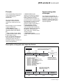
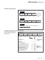
Presentation
Introduction
The "GTC link" communication
interface is designed to transmit
MGETM GalaxyTM 6000 UPS
operating information and remote
"on/off" commands (if available) to
an external computer.
The JBUS hexadecimal
communication protocol is used
(the JBUS ASCII mode is not used
in this application).
The "GTC link" features two
symmetrical communication
channels, both with a simplified
V24 (RXD and TXD only) and an
RS485 interface.
It consists of a "GTCZ"
communication board (central unit)
and a "RAUZ 1" (communication
network management and
interconnection board).
In option, two additional
communication ports can be added:
"GT2Z" board (central unit) and
"RAUZ 2" board (communication
network management and
interconnection board).
Refer to the "communication
options connection manual" of
MGETM GalaxyTM 6000 nr
6739388XU, for all informations
about connections.
Page 4 - 6739389EN/FB
"GTCZ" and "GT2Z"
boards features
The "GTCZ" and "GT2Z" boards
are functionally divided into two
main modules:
The ACQ module
The COM module
performs data acquisition;
monitors the status bus of the
monitor/control boards;
◗ computes physical quantities and
battery backup time;
◗ processes alarms;
◗ sends commands to monitor/
control boards;
◗ stores configurable parameters
and communicates with the "Soft
Tunor" software, used by APC by
Schneider Electric after-sales
service;
◗ transfers data using the on-board
communication channels.
The COM communication module
is designed for external devices
(e.g. "AMUZ" type board of a
"Monitor" or "Tele-Monitor") to:
◗ retrieve information and
parameters processed by the ACQ;
◗ send commands to monitor/
control boards;
◗ be integrated into other systems
(remote indications and
supervision).
◗
◗
Each "GTCZ" or "GT2Z" board is
equipped with two symmetrical
communication ports, COM1 and
COM2:
◗ on the "GTCZ" board:
◗ COM1 for a "display devices"
network consisting of "AMUZ"
boards in a unitary or parallel
connected UPS configurations,
◗ COM2 for a supervisory system;
◗ on the "GT2Z" board:
◗ COM1 and COM2 for a
supervisory system.
The "GTCZ" and "GT2Z" boards
are configured with the APC by
Schneider Electric after-sales
customization software called "Soft
Tunor".
The computer link is via the test
connector located on the front
panel of the cubicles and performs:
◗ configuration, calibration and
control of the ACQ module;
◗ configuration of COM1 and
COM2 ports.
Communication settings
The COM1 and COM2
communication ports can be
configured as follows:
◗ data rate: 1200, 2400, 4800,
9600 Baud;
◗ data bits: 8 (always);
◗ parity: none, odd, even;
◗ stop bits: 1 or 2;
◗ slave address: 20H to F8H in
increments of 8H;
◗ interface:
◗ 0 = RS232 simplified,
◗ 1 = RS232 complete
(not implemented),
◗ 2 = RS485;
command masks;
other parameters (modem type,
telephone number, handshaking,
modem protocol, password)
reserved for later use.
◗
◗
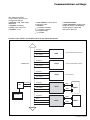
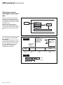
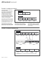
Location of the "GTCZ" and "GT2Z" boards in the cubicle electronics
Acquisition
Status
CRIZ
(only in rectifier-inverter cubicle)
CROZ
(only in rectifier-inverter cubicle)
AROZ
(in all cubicles)
Test channel
Acquisition
INTERNAL BUS
Status
Test channel
Acquisition
Status
Test channel
Test channel
SRIZ
Status
Acquisition
COM1
Status
Test channel
GTCZ
RAUZ 1
COM2
Commands
Soft Tunor
Acquisition
COM1
Status
Test channel
GT2Z
RAUZ 2
COM2
Commands
6739389EN/FB -
Page 5
JBUS protocol
Introduction
JBUS protocol can be used to read
or write one or more bits or words.
In the interest of simplicity, this
document describes only the
procedures necessary for operation
and monitoring of the APC by
Schneider Electric unit.
Master
request
response
Slave
Slave
Slave
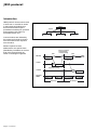
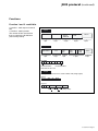
Communications are initiated by
the master and include a request
from the master and a response
from the slave.
Master requests must be
addressed to one specific slave
(identified by its address in the first
byte of the request frame) as
shown in the diagram opposite:
Response analysis
and preparation
of next exchange
Wait
Wait
MASTER
request
request
to slave 1
to slave N
SLAVE 1
response
request processing
SLAVE N
response
PHYSICAL
MEDIA
Exchange i
Page 6 - 6739389EN/FB
Exchange i+1
JBUS protocol (continued)
Principle
A full understanding of the protocol
is only required if the master is a
computer that must be
programmed.
All communications include 2
messages: a request from the
master and a response from the
slave.
Each message or frame containes
4 types of information:
◗ slave address (1 byte)
The slave address specifies the
destination station (see address
list):
◗ unitary rectifier-inverter cubicle,
◗ parallel rectifier-inverter cubicle,
◗ Static Switch cubicle.
If zero, the request addresses all
slaves and there is no response
message (in which case it is a
broadcast message, a function not
used in this application);
◗ function code (1 byte)
Selects a command (e.g. read or
write a bit or a word) and checks
that the response is correct.
The JBUS protocol comprises 10
functions of which 3 may be used in
this application: function 3 (read n
output or internal words), or
function 4 (read n input words), or
function 16 (write n words);
◗ information field (n bytes)
The information field contains the
parameters related to the functions:
bit address, word address, bit
value, word value, number of bits,
number of words;
◗ check word (2 bytes)
A word used to detect transmission
errors.
Synchronizing data
exchanges
Any character received after 3 or
more character lengths of silence is
interpreted as the start of a frame.
Therefore, a minimum silence of 3
character lengths between frames
must be respected.
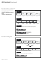
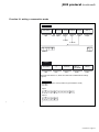
Description of request and response frames
request
1 byte
slave adress
(1 à FF)
1 byte
function
code
information requested: bit/word address,
bit/word value, bit/word number.
2 bytes
check word
information
n bytes
This function code selects one of
10 possible commands:
- Function 1 : read n output or internal bits
- Function 2 : read n input bits
- Function 3 : read n output or internal words
- Function 4 : read n input words
- Function 5 : write one bit
- Function 6 : write one word
- Function 8 : data exchange diagnostics
- Function 11 : read event counter
- Function 15 : write n bits
- Function 16 : write n words
values of bits or words read
values of bits or words written
number of bits or words
response
slave adress
(1 à FF)
1 byte
When the message is
received, the slave reads
the check word and accepts
or refuses the message
function
code
data
1 byte
◗ bytes
CRC
check word
2 bytes
6739389EN/FB -
Page 7
JBUS protocol (continued)
Checking received
messages on the slave
side
After the master sends a request
containing the slave address, the
function code and data, it computes
the CRC and sends it as the check
word (CRC 16).
When the slave receives the
request, it stores the message in
memory and calculates the CRC 16
to compare it to the received CRC
16.
If the message is incorrect (unequal
CRC 16 values), the slave does
not respond.
If the message received is correct
but the slave is unable to process it
(incorrect address, incorrect data,
etc.), the slave returns an error
message with the following
contents (see opposite):
slave
master
slave address
CRC 16
computation
function
data
CRC 16
CRC 16 comparison
Error codes:
1. Unknown function code
2. Incorrect address
3. Incorrect data
4. Station not ready
8. Write error
9. Field overlap
response
function code
received and
MS bit = 1
slave
address
(1 à FF)
1
CRC 16
1 byte
1 byte
1 byte
example
Page 8 - 6739389EN/FB
errors handled
by the
communication
port
01
09 H 00
01
89 H
01
00
00
86 50
00
DD CB
request
response
2 bytes
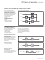
JBUS protocol (continued)
Functions
Function 1 and 2: read N bits
function 1: read output or internal
bits;
◗ function 4: read input bits.
The number of bits must be less
than or equal to the bit field size
(see memory board).
◗
request
slave address
address of
first bit
MSB LSB
1 or 2
1 byte
1 byte
number of bits
to read
2 bytes
CRC 16
2 bytes
2 bytes
response
slave address
number of
bytes
read
1 or 2
1 byte
1 byte
first
byte
read
1 byte
last
byte
read
CRC 16
✷ bytes
2 bytes
byte detail:
last bit transmitted
first bit transmitted
Unused bits are set to zero
example
Reading bits at location 404 to 411 of slave at address 20H (charger signals)
request:
20
01
0404
0E
66 FE
response:
20
01
02 10101001
40B
00101110
404 411
FB B7
40C (binary values)
6739389EN/FB -
Page 9
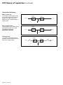
JBUS protocol (continued)
Function 3 and 4: read N words
The number of words must be less
than or equal to the word field size
(see memory board).
◗ function 3: read output or internal
words;
◗ function 4: read input words.
request
slave address
3 or 4
1 byte
adress of
first bit
MSB
LSB
number of
words
MSB
LSB
2 bytes
2 bytes
1 byte
CRC 16
2 bytes
response
slave address
number of
bytes read
3 or 4
1 byte
1 byte
1 byte
first word
last word
PF
PF
pf
2 bytes
2 bytes
CRC 16
pf
2 bytes
example
Reading words at location 146 to 14B of slave at address 28H (voltage fields)
request:
28
03
0146
06
A7 E0
response:
28
03
0C
XXXX
YYYY
word 0146
word 014B
CRC 16
Function 5: writing a bit
request
slave address
1 byte
5
bit address
2 bytes
1 byte
bit value
0
1 byte
bit set to 0
bit set to 1
1 byte
CRC 16
2 bytes
write 0
write FF
response
slave address
5
bit address
bit value
In function 5 the response and request frames are identical.
example
Setting bit location C05 to 1 of slave at address 40H (inverter on)
request:
40
Page 10 - 6739389EN/FB
05
0C05
FF
00
90 7A
0
CRC 16
JBUS protocol (continued)
Function 6: writing a word
request
slave address
6
word address
word
CRC 16
1 byte
1 byte
2 bytes
2 bytes
2 bytes
6
word address
word
CRC 16
response
slave address
The response is echoed acknowledging that the word sent has been received.
example
Writing the value 1000 into the word location 810H of slave at address 50H
50
06
08 10
10 00
8A 2E
Function 8: reading error diagnosis counters
Each slave manages a set of nine
16 bit counters for error diagnosis
(see opposite):
- request / response:
slave address
1 byte
8
sub-function
code
1 byte
data
2 bytes
2 bytes
- the slave must echo
the request
00
XYZT
- reset error
diagnosis counter
0A
0000
0B
XXXX
CRC 16
2 bytes
X, Y, Z, T are user
defined (transmission
parameters)
- read the total number of:
received frames with CRC error (CNT 1)
received frames with CRC error (CNT 2)
0C
XXXX
number of exception responses (CNT 3)
0D
XXXX
frames addressed to the station (CNT 4)
(not including broadcast)
broadcast requests received (CNT 5)
0E
XXXX
0F
XXXX
number of NACK responses (CNT 6)
unit not ready responses (CNT 7)
10
11
XXXX
XXXX
illegal characters (CNT 8)
12
XXXX
requests:
XXXX equals 0000
response:
XXXX is the counter
value
6739389EN/FB -
Page 11
JBUS protocol (continued)
Function 11: reading event counters
The master and each slave have
one event counter.
This counter is incremented each
time a frame is received and
interpreted correctly by the slave
(except for function 11 itself).
A correctly transmitted message
increments the counter. If the slave
sends an exception response, the
counter is not incremented.
request
slave address
response
slave address
The master can read the counter to
determine whether or not the slave
correctly interpreted the command
(incremented the counter or not).
These functions can be used to
diagnose the data exchange taking
place between master and slaves.
CRC 16
0B
1 byte
1 byte
0
slave
counter word
CRC 16
2 bytes
2 bytes
2 bytes
0B
If the master counter equals the
slave counter, the slave executed
the command sent by the master.
If the master counter is one higher
than the slave counter, the slave
did not execute the command sent
by the master.
Function 15: writing n consecutive bits
request
slave adress
1 byte
address of
the first bit
0F
1 byte
2 bytes
number
of bits
number
of bytes
bit data
CRC 16
2 bytes
1 byte
n bytes
2 bytes
2 X 1968
réponse
1 N 246
first bit of
first byte
last bit of
first byte
first bit of
byte N
last bit of
byte N
first byte
N bytes
response
slave address
1 byte
0F
1 byte
address of
the first bit
number of bits
CRC 16
2 bytes
2 bytes
1 X 1968
2 bytes
Note: if the slave address is 0, all units execute the write command without sending a
response.
Page 12 - 6739389EN/FB
JBUS protocol (continued)
Function 16: writing n consecutive words
request
slave address
1 byte
10
(*)
address of
first word
1 byte
2 bytes
number
of words
number
of bytes N
data bytes
1 byte
n bytes
2 bytes
CRC 16
2 bytes
2 X 123
4 N 246
MSB LSB MSB LSB MSB
MSB LSB
last word
first word
response
slave address
1 byte
10
(*)
1 byte
address of
first word
number of
words written
CRC 16
2 bytes
2 bytes
2 bytes
Note: if the slave address is 0, all units execute the write command without sending a
response
example
Writing words 00 and 01 of slave at address 20 (synchronization counter)
(00) = 0000
(01) = 0000
request
20
10
(*) 0000 0002 04
0000 0000 0000 0000
5C 93
response
20
)
*
10
(*) 0000 0002 47 79
(
6739389EN/FB -
Page 13
JBUS protocol (continued)
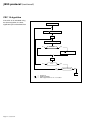
CRC 16 algorithm
If the CRC 16 is calculated using
the above algorithm, the least
significant byte is transmitted first.
Hex FFFF --> CRC 16
CRC 16
BYTE --> CRC 16
n=0
CRC 16 shift to the right
no
remainder
yes
CRC 16
poly --> CRC 16
n = n+1
no
yes
n>7
no
following byte
end of message
yes
END
n
poly
Page 14 - 6739389EN/FB
=
=
=
exclusive or
number of data bits
CRC 16 polynomial = 215 + 213 + 20 = $ A001
JBUS protocol (continued)
Example of CRC computation
CRC register initialization
of 1st character
Set flag to 1,
Set flag to 1,
Shift 1
1111
1111
1111
0000
1111
0010
Shift 1
1111
0111
1010
1111
1111
0000
1111
1111
0000
1101
1110
0001
1
Shift 2
1101
0110
1010
1111
1111
1111
1111
1111
1111
0001
1
Shift 3
Shift 4
1100
0110
0011
101
1111
0111
0011
1111
1111
1111
1110
1111
1111
1
0
1
Shift 5
Shift 6
1001
0100
0010
101
0011
1001
0100
1111
1111
1111
1110
1111
1111
1
0
1
Shift 7
Shift 8
1000
0100
0010
101
0100
0010
0001
1111
0111
0011
1110
1111
1111
1
0
1
1000
0001
0011
0000
1110
0111
Shift 1
1000
0100
101
0001
0000
0011
1001
1001
1101
1
1
Shift 2
1110
0111
101
0000
0000
1001
0100
1101
1110
1
1
Shift 3
1101
0110
101
0000
1000
0100
0010
1111
0111
1
1
Shift 4
Shift 5
1100
0110
0011
101
1000
0100
0010
0010
0001
0000
0110
0011
1001
1
0
1
Shift 6
Shift 7
Shift 8
1001
0100
0010
0001
0010
1001
0100
0010
0000
0000
1000
0100
1000
0100
0010
0001
0
0
0
polynomial
polynomial
Set flag to 0
2nd character
byte
byte
6739389EN/FB -
Page 15
JBUS protocol (continued)
Example of CRC 16 computation in "C" using table lookup
#define CPH 0 /* most significant bytes */
#define CPL 1 /* least significant bytes */
/* TABLE OF MOST SIGNIFICANT BYTES FOR CRC16 COMPUTATION */
char tbcrch [ ] =
{
0,193,129,64,1,192,128,65,1,192,128,65,0,193,129,64,
1,192,128,65,0,193,129,64,0,193,129,64,1,192,128,65,
1,192,128,65,0,193,129,64,0,193,129,64,1,192,128,65,
0,193,129,64,1,192,128,65,1,192,128,65,0,193,129,64,
1,192,128,65,0,193,129,64,0,193,129,64,1,192,128,65,
0,193,129,64,1,192,128,65,1,192,128,65,0,193,129,64,
0,193,129,64,1,192,128,65,1,192,128,65,0,193,129,64,
1,192,128,65,0,193,129,64,0,193,129,64,1,192,128,65,
1,192,128,65,0,193,129,64,0,193,129,64,1,192,128,65,
0,193,129,64,1,192,128,65,1,192,128,65,0,193,129,64,
0,193,129,64,1,192,128,65,1,192,128,65,0,193,129,64,
1,192,128,65,0,193,129,64,0,193,129,64,1,192,128,65,
0,193,129,64,1,192,128,65,1,192,128,65,0,193,129,64,
1,192,128,65,0,193,129,64,0,193,129,64,1,192,128,65,
1,192,128,65,0,193,129,64,0,193,129,64,1,192,128,65,
0,193,129,64,1,192,128,65,1,192,128,65,0,193,129,64,
};
/* TABLE OF LEAST SIGNIFICANT BYTES FOR CRC16 COMPUTATION */
char tbcrcl [ ] =
{
0,192,193,1,195,3,2,194,198,6,7,199,5,197,196,4,
204,12,13,205,15,207,206,14,10,202,203,11,201,9,8,200,
216,24,25,217,27,219,218,26,30,222,223,31,221,29,28,220,
20,212,213,21,215,23,22,214,210,18,19,211,17,209,208,16,
240,48,49,241,51,243,242,50,54,246,247,55,245,53,52,244,
60,252,253,61,255,63,62,254,250,58,59,251,57,249,248,56,
40,232,233,41,235,43,42,234,238,46,47,239,45,237,236,44,
228,36,37,229,39,231,230,38,34,226,227,35,225,33,32,224,
160,96,97,161,99,163,162,98,102,166,167,103,165,101,100,164,
108,172,173,109,175,111,110,174,170,106,107,171,105,169,168,104,
120,184,185,121,187,123,122,186,190,126,127,191,125,189,188,124,
180,116,117,181,119,183,182,118,114,178,179,115,177,113,112,176,
80,144,145,81,147,83,82,146,150,86,87,151,85,149,148,84,
156,92,93,157,95,159,158,94,90,154,155,91,153,89,88,152,
136,72,73,137,75,139,138,74,78,142,143,79,141,77,76,140,
68,132,133,69,135,71,70,134,130,66,67,131,65,129,128,64,
};
Page 16 - 6739389EN/FB
JBUS protocol (continued)
*/ **************************************************************************************************** */
/*
FUNCTION CALL: crc = crc16 (message, length);
*/
/*
with char *message; message = address of message
*/
/*
*/
/*
int length; length of received message (including CRC)
*/
/*
expressed in number of bytes
*/
/*
int crc; = CRC16 calculated from the "address", "code" and
*/
/*
"information" fields.
*/
/*
*/
/*
RETURN VALUE: calculated crc 16 (int crc)
*/
/***************************************************************************************************** */
int crc16 (message, length)
unsigned char message [ ];
int length;
{
int i ;
int j ;
union {
int ival ;
unsigned char cval [ 2 ];
/*
/*
/*
/*
/*
/*
/*
/*
/*
/*
/*
/*
/*
buffer containing message
for which the crc16 is to be calculated.
length of message to be checked
(including crc16)
beginning of the function
loop variable
calculation and displacement variable
calculated crc16:
- whole
- table of 2 characters
unsigned is important since otherwise the sign
extension causes negative displacements with
respect to the beginning of the table
*/
*/
*/
*/
*/
*/
*/
*/
*/
*/
*/
*/
*/
} crcal;
/*$ initialization of calculated crc
*/
/*$ correction of the length to be checked: remove the
/*$ received crc16 from the length to be checked
*/
*/
/*$ WHILE there are bytes to be checked DO
*/
crcal.ival = 0XFFFF;
i = 0;
length = length - 2;
while ( i < length )
{
/*$ calculate the table index
j = (int) ( message [ i ] ^ crcal.cval [ CPH ] );
/*$ most significant byte
crcal.cval [ CPH ] = tbcrch [ j ] ^ crcal.cval [ CPL ];
/*$ least significant byte
crcal.cval [ CPL ] = tbcrcl [ j ];
/*$ next byte
i++;
};
/*$ END WHILE there are bytes to be checked
/*$ return the calculated crc
return ( crcal.ival );
}
/* end of function
*/
*/
*/
*/
*/
*/
*/
Note: if the CRC16 is computed
using table lookup, the most
significant byte is transmitted first.
6739389EN/FB -
Page 17
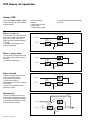
UPS theory of operation
Unitary UPS
The unitary MGETM GalaxyTM 6000
UPSs are made up of five modular
sub-assemblies:
◗
◗
◗
◗
◗
rectifier-charger;
battery;
three-phase inverter;
static switch;
maintenance bypass.
The load and Mains 2 operate at 50
or 60 Hz.
Mains 1 power up
the inverter receives power from
the rectifier-charger and supplies
power to the load. There is no
direct connection between Mains
and load;
◗ the battery is charged or the
charge maintained.
static by-pass switch
◗
Mains 2
rectifiercharger
inverter
Mains 1
load
battery
Mains 1 power down
the inverter receives power from
the battery and supplies power to
the load;
◗ the battery discharges.
static by-pass switch
◗
Mains 2
rectifiercharger
inverter
Mains 1
load
battery
Major overload
Mains 2 supplies power to the
load via the static switch;
◗ the inverter is shut down;
◗ the inverter starts-up
automatically as soon as overload
is removed;
◗ power is transferred without
affecting the load.
static by-pass switch
◗
Mains 2
rectifiercharger
inverter
Mains 1
load
battery
Maintenance
Mains 2 supplies power to the
load via the maintenance bypass;
◗ the rectifier-charger and inverter
are shut down and disconnected
from all sources of power.
Q3BP
◗
static by-pass switch
Q4S
Mains 2
rectifiercharger
inverter
Q1
Q5N
load
Mains 1
QF1
battery
Page 18 - 6739389EN/FB
UPS theory of operation (continued)
Parallel connected UPS with "Static Switch" cubicle
Up to six parallel connected
rectifier-inverter cubicles can be
combined with one "Static Switch"
cubicle to form a system that
operates like a unitary UPS system.
Each parallel connected rectifierinverter cubicle houses a:
◗ rectifier-charger;
◗ battery;
◗ three-phase inverter.
The "Static Switch" cubicle
contains:
◗ static by-pass switch;
◗ maintenance bypass.
The units have separate batteries:
static by-pass switch
Mains 2
rectifiercharger
inverter
Mains 1
battery
rectifiercharger
inverter
Mains 1
load
battery
UPS without Mains 2
All UPSs without Mains 2 contain
the same sub-assemblies:
◗ rectifier-charger;
◗ battery (option);
◗ three-phase inverter.
They may or may not be parallel
connected depending on type and
may or may not contain a battery.
The output voltage has a frequency
of 50 or 60 Hz.
Operation without battery
Mains 1 power up:
◗ the inverter receives power from
the rectifier-charger and supplies
power to the load. There is no
direct connection between Mains 1
and the load.
rectifiercharger
inverter
Mains 1
load
Mains 1 power down:
◗ no power to the load.
rectifiercharger
inverter
Mains 1
Maintenance position
(disconnected):
◗ no power to the load (except in
parallel connected systems, where
other units supply power).
load
rectifiercharger
Q1
Mains 1
inverter
Q5N
load
6739389EN/FB -
Page 19
UPS theory of operation (continued)
Operation with battery
Mains 1 power up:
◗ the inverter receives power from
the rectifier-charger and supplies
power to the load. There is no
direct connection between Mains 1
and the load.
Mains 1 power down:
◗ the inverter runs on battery power
and supplies power to the load;
◗ the battery discharges.
Maintenance position
rectifiercharger
inverter
Mains 1
load
battery
rectifiercharger
inverter
Mains 1
load
battery
(disconnected):
◗ no power to the load (except in
parallel connected systems, where
other units supply power).
rectifiercharger
inverter
Q1
Q5N
load
Mains 1
QF1
battery
Page 20 - 6739389EN/FB
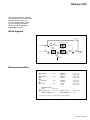
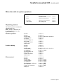
Unitary UPS
This chapter presents the specific
operating aspects and system data
provided by the "GTCZ" and
"GT2Z" boards in unitary UPSs.
For more detailed information,
please refer to the "system
information" section.
Block diagram
Q3BP
Q4S
static by-pass switch
a
Mains 2
rectifiercharger
inverter
Q1
Q5N
K3N
Mains 1
load
b
e
c
d
QF1
battery
Measured quantities
a
F Mains 2
<1A2>
U Mains 2
I Mains 2
<149 to 14E>
<109 to 10B>
b
F Mains 1
<1A0>
U Mains 1
I Mains 1
<140 to 142>
<100 to 102>
F inverter
<1A1>
U inverter
I inverter
<143 to 148>
<106 to 108>
F load
<1A3>
U load
I load
<14F to 154>
<10C to 10E>
U battery or U dc
Battery temperature
<155 or 1C0>
<1C3>
c
d
Apparent and active
power
<180 to 187>
e
I battery or I dc
<115 or 1C1>
Battery backup time <1C2>
The numbers enclosed by <> are the addresses in the data array.
6739389EN/FB -
Page 21
Unitary UPS (continued)
Main status bits (UPS operating information)
Normal
:
inverter powers load and full backup
time available
bit 4C4 = 1
Danger
:
inverter does not power load
bit 4C6 = 1
Downgraded
:
malfunction or environment fault
bit 4C5 = 1
Load on battery
:
fonctionnement en autonomie
bit 4C7 = 1
Operating modes
The following section describes the
different states of a
MGETM GalaxyTM 6000 UPS and
the addresses of the bits in the
system data array.
Normal operation
Normal:
Danger:
Downgraded:
Load on battery:
Q1 closed:
Rectifier/charger on:
QF1 closed:
Inverter connected:
Q5N closed:
Q3BP open:
Q4S closed:
SS open:
K2S open (if available):
bit 4C4 = 1
bit 4C6 = 0
bit 4C5 = malfunction dependent
bit 4C7 = 0
bit 40E = 1
bit 408 = 1
bit 400 = 1
bit 484 = 1
bit 498 = 1
bit 497 = 0
bit 496 = 1
bit 499 = 0
bit 494 = 0
Load on battery
Normal:
Danger:
Downgraded:
Load on battery:
Q1 indifferent:
Rectifier/charger off:
QF1 closed:
Inverter connected:
Q5N closed:
Q3BP open:
Q4S closed:
SS open:
K2S open (if available):
bit 4C4 = 1
bit 4C6 = 0
bit 4C5 = malfunction dependent
bit 4C7 = 1
bit 40E = X (N/A)
bit 408 = 0
bit 400 = 1
bit 484 = 1
bit 498 = 1
bit 497 = 0
bit 496 = 1
bit 499 = 0
bit 494 = 0
Page 22 - 6739389EN/FB
Unitary UPS (continued)
Load on Mains 2
Normal:
Danger:
Downgraded:
Load on battery:
Q1 indifferent:
Rectifier/charger indifferent:
QF1 indifferent:
Inverter disconnected:
Q5N closed:
Q3BP open:
Q4S closed:
SS closed:
K2S closed (if available):
bit 4C4 = 0
bit 4C6 = 1
bit 4C5 = X (N/A)
bit 4C7 = X (N/A)
bit 40E = X (N/A)
bit 408 = X (N/A)
bit 400 = X (N/A)
bit 484 = 0
bit 498 = 1
bit 497 = 0
bit 496 = 1
bit 499 = 1
bit 494 = 1
Load on bypass
Normal:
Danger:
Downgraded:
Load on battery:
Q1 indifferent:
Rectifier/charger indifferent:
QF1 indifferent:
Inverter connected indifferent:
Q5N open:
Q3BP closed:
Q4S indifferent:
SS indifferent:
K2S indifferent:
bit 4C4 = 0
bit 4C6 = 1
bit 4C5 = X (N/A)
bit 4C7 = X (N/A)
bit 40E = X (N/A)
bit 408 = X (N/A)
bit 400 = X (N/A)
bit 484 = X (N/A)
bit 498 = 0
bit 497 = 1
bit 496 = X (N/A)
bit 499 = X (N/A)
bit 494 = X (N/A)
6739389EN/FB -
Page 23
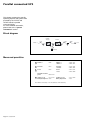
Parallel connected UPS
This chapter presents the specific
operating aspects and system data
provided by the "GTCZ" and
"GT2Z" boards in parallel
connected UPSs.
For more detailed information,
please refer to the "system
information" section.
Block diagram
rectifiercharger
inverter
Q1
Q5N
K3N
Mains 1
load
b
e
c
d
QF1
battery
Measured quantities
b
F Mains 1
<1A0>
U Mains 1
I Mains 1
<140 to 142>
<100 to 102>
c
F inverter
<1A1>
U inverter
I inverter
<143 to 148>
<106 to 108>
d
F load
<1A3>
U load
I load
<14F to 154>
<10C to 10E>
U battery or U dc
Battery temperature
<155 or 1C0>
<1C3>
Apparent and active
power
<180 to 187>
e
I battery or I dc
<115 or 1C1>
Battery backup time <1C2>
The numbers enclosed by <> are the addresses in the data array.
Page 24 - 6739389EN/FB
Parallel connected UPS (continued)
Main status bits of system operations
Normal
:
inverter powers load and maximum
backup time available
bit 4C4 = 1
Danger
:
inverter does not power load
bit 4C6 = 1
Downgraded
:
malfunction or environment fault
bit 4C5 = 1
Load on battery
:
load on battery power
bit 4C7 = 1
Operating modes
The following section describes the
different states of a
MGETM GalaxyTM 6000 UPS and
the addresses of the bits in the
system data array.
Normal operation
Normal:
Danger:
Downgraded:
Load on battery:
Q1 closed:
Rectifier/charger on:
QF1 closed:
Inverter connected:
Q5N closed:
bit 4C4 = 1
bit 4C6 = 0
bit 4C5 = malfunction dependent
bit 4C7 = 0
bit 40E = 1
bit 408 = 1
bit 400 = 1
bit 484 = 1
bit 498 = 1
Load on battery
Normal:
Danger:
Downgraded:
Load on battery:
Q1 indifferent:
Rectifier/charger off:
QF1 closed:
Inverter connected:
Q5N closed:
bit 4C4 = 1
bit 4C6 = 0
bit 4C5 = malfunction dependent
bit 4C7 = 1
bit 40E = X (N/A)
bit 408 = 0
bit 400 = 1
bit 484 = 1
bit 498 = 1
Disconnected
Normal:
Danger:
Downgraded:
Load on battery:
Q1 indifferent:
Rectifier/charger indifferent:
QF1 indifferent:
Inverter not connected:
Q5N open:
bit 4C4 = 0
bit 4C6 = 1
bit 4C5 = X (N/A)
bit 4C7 = X (N/A)
bit 40E = X (N/A)
bit 408 = X (N/A)
bit 400 = X (N/A)
bit 484 = X (N/A)
bit 498 = 0
6739389EN/FB -
Page 25
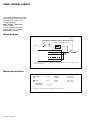
Static Switch cubicle
This chapter presents the specific
operating aspects and system data
provided by the "GTCZ" and
"GT2Z" boards for
MGETM GalaxyTM 6000 "Static
Switch" cubicles.
For more detailed information,
please refer to the "system
information" section.
Block diagram
Q3BP
static by-pass switch (SS and K2S*)
Q4S
a
Mains 2
Q5N
inverter 1
inverter 2
load
b
inverter n
* : K2S is the contactor that is parallel-mounted with the static switch on devices with an output
greater than 800 kVA.
Measured quantities
a
F Mains 2
<1A2>
U Mains 2
I Mains 2
<149 to 14E>
<109 to 10B>
b
F load
<1A3>
U load
I load
<14F to 154>
<10C to 10E>
Apparent and
active power
<180 to 187>
The numbers enclosed by <> are the addresses in the data array.
Page 26 - 6739389EN/FB
Static Switch (continued)
Main indicators of system operations
Normal
:
charge alimentée par l'onduleur
bit 4C4 = 1
Danger
:
charge non alimentée par l'onduleur
bit 4C6 = 1
Downgraded
:
anomalie de fonctionnement
ou défaut d'environnement
bit 4C5 = 1
Operating modes
The following section describes the
different states of a Static Switch
cubicle and the addresses of the
bits in the system data array.
Normal operation
Normal:
Danger:
Downgraded:
Q5N closed:
Q3BP open:
Q4S closed:
SS open:
K2S open (if available):
Inverters connected to load:
bit 4C4 = 1
bit 4C6 = 0
bit 4C5 = malfunction dependent
bit 498 = 1
bit 497 = 0
bit 496 = 1
bit 499 = 0
bit 494 = 0
bit 4AE = 1
Load on Mains 2
Normal:
Danger:
Downgraded:
Q5N closed:
Q3BP open:
Q4S closed:
SS closed (if K2S not available):
K2S closed (if available):
Inverters not connected to load:
bit 4C4 = 0
bit 4C6 = 1
bit 4C5 = X (N/A)
bit 498 = 1
bit 497 = 0
bit 496 = 1
bit 499 = 1
bit 494 = 1
bit 4AE = 0
Load on bypass
Normal:
Danger:
Downgraded:
Q5N open:
Q3BP closed:
Q4S indifferent:
CS indifférent:
SS indifferent:
Inverter connected indifferent:
bit 4C4 = 0
bit 4C6 = 1
bit 4C5 = X (N/A)
bit 498 = 0
bit 497 = 1
bit 496 = X (N/A)
bit 499 = X (N/A)
bit 494 = X (N/A)
bit 4AE = X (N/A)
6739389EN/FB -
Page 27
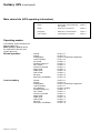
System information
Message format
This section describes the
messages exchanged between the
"GTC link" communication interface
and the external computer based
on the JBUS protocol.
The length of time after which a
message must be interpreted as
"not understood" depends on the
type of command sent.
The table opposite lists maximum
response times:
Data rate
status information only
all measurements
1200 Baud
0,5 s
2s
2400 Baud
0,25 s
1s
Response time of event (independent of data rate)
- inverter start-up and connect
:
- rectifier-charger startup
:
- rectifier-charger or inverter stop
:
4800 Baud
0,12 s
0,5 s
9600 Baud
0,06 s
0,25 s
30 s
30 s
30 s
Example of read data array commands sent by the terminal
(address: 20H)
For the "responses", refer to the
"JBUS protocol" section function 1
and 3.
request
station
data
address
0140
length
CRC 16
20
function
code
03
read voltage
array
(21 values)
read current
array
(15 values)
read global
state bits
(11 bits)
0015
82 9C
20
03
0100
000F
28 03
20
01
04C0
000B
7A 70
Sample commands
command
station
charger on
charger off
inverter on
inverter off
20
20
20
20
function
code
05
05
05
05
bit
address
0C00
0C01
0C04
0C05
data
FF
FF
FF
FF
not
used
00
00
00
00
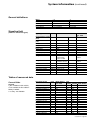
List of variable fields
(same for all cubicle types)
The binary data and binary
commands can be accessed bit or
word-wise.
The word address and position of
the bit in the word can be
determined from the bit address:
◗ hundreds and tens digit of bit
address = word address;
◗ least significant digit of bit
address = bit position.
Page 28 - 6739389EN/FB
JBUS fields
signaling
signaling
binary data
commands
counters
currents
voltages
powers
frequencies
battery
adjustments
maintenance
address in hexadecimal
start
end
0
5
6
F
40
BF
C0
DF
E0
FF
100
13
140
17
180
19F
1A0
1BF
1C0
1DF
200
2FF
300
3FF
access
read / write
read
read
read / write
read
read
read
read
read
read
read
read
CRC 16
89 DB
D8 1B
C8 1A
99 DA
System information (continued)
General definitions
object
switch
unit
fault
control device
0
open
off
no fault
not activated
1
closed
on
fault
activated
Signaling field
(same for all cubicle types)
signaling
units
data
JBUS address
hex. word
0
synchronisation counter
(MSB)
synchronisation counter
(LSB)
binary times
binary times
binary times
binary times
manufacturer's ID
model ID (MSB)
model ID (LSB)
configuration 1
ms
0
without
without
without
without
configuration 2
without
N/A
N/A
N/A
N/A
1
102
54380
N/A
inverter type,
same as 200
hardware version
software version
not used
not used
state of equipment
state of processing
not used
not used
without
without
measured current
units
I1 (I phase 1) Mains 1
I2 (I phase 2) Mains 1
I3 (I phase 3) Mains 1
I1 (I phase 1) inverter
I2 (I phase 2) inverter
I3 (I phase 3) inverter
I1 (I phase 1) Mains 2
I2 (I phase 2) Mains 2
I3 (I phase 3) Mains 2
I1 (I phase 1) load
I2 (I phase 2) load
I3 (I phase 3) load
I battery
% load
% peak load (Ph1)
% peak load (Ph2)
% peak load (Ph3)
A
A
A
A
A
A
A
A
A
A
A
A
A
-
4294967295 1
same as 4E
same as 4C
2
3
4
5
MSB 6
LSB 6
7
MSB 8
LSB 8
MSB 9
LSB 9
A
B
C
D
E
F
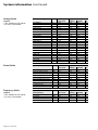
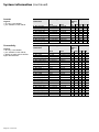
Tables of measured data
Current fields
Legend:
◗ yes: available in this cubicle;
◗ bat: available in this cubicle if
battery installed;
◗ no entry: not available.
JBUS address
hex. word
100
101
102
106
107
108
109
10A
10B
10C
10D
10E
115
120
121
122
123
type
unitary
yes
yes
yes
yes
yes
yes
yes
yes
yes
yes
yes
yes
bat
yes
yes
yes
yes
parallel Static Switch
yes
yes
yes
yes
yes
yes
yes
yes
yes
yes
yes
yes
yes
yes
yes
bat
yes
yes
yes
yes
yes
yes
yes
yes
6739389EN/FB -
Page 29
System information (continued)
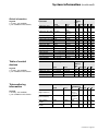
Voltage fields
Legend:
◗ yes: available in this cubicle;
◗ no entry: not available.
Power fields
Frequency fields
Legend:
◗ yes: available in this cubicle;
◗ no entry: not available.
Page 30 - 6739389EN/FB
measured voltage
units
U12 Mains 1
U23 Mains 1
U31 Mains 1
U1N inverter
U2N inverter
U3N inverter
U12 inverter
U23 inverter
U31 inverter
U1N Mains 2
U2N Mains 2
U3N Mains 2
U12 Mains 2
U23 Mains 2
U31 Mains 2
U1N load
U2N load
U3N load
U12 load
U23 load
U31 load
U battery
V
V
V
V
V
V
V
V
V
V
V
V
V
V
V
V
V
V
V
V
V
V
power measurements
units
P1 (load active power)
P2 (load active power)
P3 (load active power)
S1 (load apparent power)
S2 (load apparent power)
S3 (load apparent power)
P (load active power)
S1 (load apparent power)
% inverter load
power factor
kW
kW
kW
kVA
kVA
kVA
kW
kVA
-
frequencies
measurements
F Mains 1
F inverter
FMains 2
F load
units
dHz
dHz
dHz
dHz
JBUS address
hex. word
140
141
142
143
144
145
146
147
148
149
14A
14B
14C
14D
14E
14F
150
151
152
153
154
155
type
unitary
yes
yes
yes
yes
yes
yes
yes
yes
yes
yes
yes
yes
yes
yes
yes
yes
yes
yes
yes
yes
yes
yes
JBUS address
hex. word
180
181
182
183
184
185
186
187
188
189
type
unitary
yes
yes
yes
yes
yes
yes
yes
yes
yes
yes
JBUS address
hex. word
1A0
1A1
1A2
1A3
type
unitary
yes
yes
yes
yes
parallel
yes
yes
yes
yes
yes
yes
yes
yes
yes
yes
yes
yes
yes
yes
yes
yes
SS
yes
yes
yes
yes
yes
yes
yes
yes
yes
yes
yes
yes
parallel
yes
yes
yes
yes
yes
yes
yes
yes
yes
yes
SS
yes
yes
yes
yes
yes
yes
yes
yes
yes
yes
parallel
yes
yes
SS
yes
yes
yes
System information (continued)
Battery and adjustments
fields
Legend:
◗ no entry: not available;
◗ yes: available in this cubicle;
◗ bat: available in this cubicle if
battery installed;
◗ bat/opt: available if option
installed.
Inverter type:
◗ 0: unitary;
◗ 1: parallel without static switch;
◗ 2: parallel with static switch;
◗ 3: Static Switch cubicle.
battery measurements
units
U battery
I battery
battery backup time
battery room temperature
V
A
mn
°C
battery adjustments
units
inverter type
battery installed
battery temperat. sensor
In (I rated load)
Pn (P rated load)
A
kW
JBUS address
hex. word
1C0
1C1
1C2
1C3
type
unitary
yes
bat
bat/opt
bat/opt
parallel
yes
bat
bat/opt
bat/opt
SS
JBUS address
hex. word
200
201
202
208
209
type
unitary
yes
yes
yes
yes
yes
parallel
yes
yes
yes
yes
yes
SS
yes
yes
yes
Battery installed:
◗ 0 = no;
◗ 1 = yes.
Sensor installed:
◗ 0 = no;
◗ 1 = yes.
Tables of binary data
Rectifier-charger
Legend:
◗ no entry: not available;
◗ yes: available in this cubicle;
◗ bat: available in this cubicle if
battery installed.
rectifier-charger
information
B_Etat_QF1
B_Etat_Dech_Bat
B_Etat_Ubat_Min
B_Etat_Ubat_Aut
B_Etat_Tempe_Ht
B_Etat_Res1_Ht
B_Etat_Vent_Bat
B_Etat_Cha_Bat
B_Etat_Pont
B_Etat_Def_Maj_Cha
B_Etat_Q1
B_Etat_Arr_Urg
B_Etat_U_Res1
B_Etat_F_Res1
B_Etat_Arr_Prog
B_Etat_Lim_Groupe
B_Etat_IBat_Aux
B_Etat_Egal_Bat
B_Etat_Groupe
bit meaning
bit=0
open
not discharging
not reached
not reached
normal
not reached
no fault
not charging
off
no fault
open
not activated
normal
normal
not activated
not activated
not activated
not active
not activated
bit=1
closed
discharging
min. volt. fault
warning
outside toleran.
outside toleran.
fault
charging
on
fault
closed
activated
outside toleran.
outside toleran.
activated
activated
activated
active
activated
JBUS
address
hex.
bit word
400 40
401
402
403
404
405
406
407
408
409
40E
411 41
412
413
417
419
41A
41B
41E
type
unit.
bat
bat
bat
bat
bat
bat
yes
bat
bat
yes
yes
yes
yes
yes
bat
bat
bat
bat
yes
para. SS
bat
bat
bat
bat
bat
bat
yes
bat
bat
yes
yes
yes
yes
yes
bat
bat
bat
bat
yes
6739389EN/FB -
Page 31
System information (continued)
Inverter
Legend:
◗ no entry: not available;
◗ yes: available in this cubicle.
Connectivity
Legend:
◗ no entry: not available;
◗ yes: available in this cubicle;
◗ >800k: on static switch cubicles
higher than 800 kVA.
Page 32 - 6739389EN/FB
inverter
information
B_Etat_Su_Mut
B_Etat_Def_Maj_Ond
B_Etat_Lim_Ond
B_Etat_Suth_Mut
B_Etat_Aux_Libre
B_Etat_Arr_Urg
B_Etat_Arr_Forc_Cext
B_Etat_Inv_Fréq
B_Etat_Arr_Prot_Cext
connectivity
information
B_Etat_Su_Ond
B_Etat_Vent
B_Etat_Ond_Coup
B_Etat_Arr_Inter
B_Etat_Cde_Pilote
B_Etat_Def_Coup
B_Etat_Res2_Ht
B_Etat_Arr_Urg
B_Etat_K2S
B_Etat_Q4S
B_Etat_Q3BP
B_Etat_Q5N
B_Etat_Cde_Cs_Res2
B_Etat_F_Res2
B_Etat_U_Res2
B_Etat_Freq_Auto
B_Etat_Su_Res2
B_Etat_Suth_Res2
B_Etat_Suth_Ond
B_Etat_Arm_Aux
B_Etat_Sans_Trou
B_Etat_Ver_Sec
B_Etat_Nb_Ond_Suff
bit meaning
JBUS
address
hex.
bit word
440 44
441
445
446
44C
44D
454 46
465
467
bit=0
no overload
no fault
no limitation
no overload
not activated
not activated
not activated
not activated
not activated
bit=1
overload
fault
limitation
overload
activated
activated
activated
activated
activated
bit meaning
JBUS
address
hex.
bit=1
bit word
overload
480 48
ventilation fault 482
connected
484
disable
485
synchro.
486
fault
487
outside toleran.48A
activated
48D
closed
494 49
closed
496
closed
497
closed
498
closed
499
outside toleran.49C
outside toleran.49D
activated
49F
overload
4A0 4A
overload
4A1
overload
4A2
fault
4A3
activated
4A4
activated
4A5
sufficient
4AF
bit=0
no overload
no fault
not connected
enable
not synchro.
no fault
normal
not activated
open
open
open
open
open
normal
normal
not activated
no overload
no overload
no overload
no fault
not activated
not activated
insufficient
type
unit.
yes
yes
yes
yes
yes
yes
yes
yes
yes
para. SS
yes
yes
yes
yes
yes
yes
yes
yes
yes
type
unit.
yes
yes
yes
yes
yes
yes
yes
yes
par.
yes
yes
yes
yes
yes
yes
yes
yes
yes
yes yes
yes
yes
yes
yes
yes
yes
yes yes
yes yes
yes
yes
SS
yes
yes
yes
yes
yes
yes
yes
yes
>800k
yes
yes
yes
yes
yes
yes
yes
yes
yes
yes
yes
yes
yes
yes
System information (continued)
Global information
Legend:
◗ no entry: not available;
◗ yes: available in this cubicle;
Table of control
devices
Legend:
◗ no entry: not available;
◗ yes: available in this cubicle.
global
information
bit meaning
bit=0
B_Etat_Arr_Acq
no fault
B_Etat_Cde_Batt_Fin no fault
B_Etat_Fin_Vie_Batt
no fault
B_Etat_Cde_Sys_Nor
B_Etat_Cde_Sys_Deg
B_Etat_Cde_Sys_Dan
B_Etat_Cde_Bat_Deg
B_Etat_Arr_Urg
B_Etat_CS_K2S
B_Etat_Coup_ASI
B_Etat_Vent_US
B_Num_Test_Com
B_Reg_Autres
B_Reg_Voie
B_Mes_Invalides
B_Etat_Modifié
no fault
not downgraded
safe
not on batteries
not activated
open
disconnected
no fault
no error
not configurated
not configurated
valid
no change
commands
bit meaning
B_Ope_Mar_Cha
B_Ope_Arr_Cha
B_Ope_Arr_Ond
B_Ope_Mar_Ond
bit=0
not activated
not activated
not activated
not activated
Telemonitoring
information
information
Legend:
◗ no entry: not available;
◗ yes: available in this cubicle.
reason for call
(high transitions)
JBUS
address
hex.
bit=1
bit word
fault
4C0 4C
backup time 4C1
end
battery
4C2
obsolete
normal
4C4
downgraded 4C5
unsafe
4C6
on batteries 4C7
activated
4C8
closed
4C9
connected
4CA
fault
4DD
error
4E9 4E
configurated 4EA
configurated 4EB
invalid
4EC
change
4EF
bit=1
activated
activated
activated
activated
bit meaning
bit=0
no transition
JBUS
address
hex.
bit
word
C00 C0
C01
C04
C05
bit=1
transition
type
unit. par. SS
yes yes yes
yes yes
yes
yes
yes
yes
yes
yes
yes
yes
yes
yes
yes
yes
yes
yes
yes
yes
yes
yes
yes
yes
yes
yes
yes
yes
yes
yes
yes
yes
yes
yes
yes
yes
yes
yes
yes
yes
yes
yes
yes
yes
yes
type
unit.
yes
yes
yes
yes
par. SS
yes
yes
yes
yes
JBUS address type
hexadecimal
bit
word unit. par. SS
(same
50
yes yes yes
structure
as word 4C)
reason for call
(low transitions)
no transition
transition
main number
invalid
secondary number
invalid
valid
invalid
520
valid
invalid
528
(same
51
yes
yes yes
52
yes
yes yes
yes
yes yes
structure
as word 4C)
6739389EN/FB -
Page 33
System information (continued)
Glossary of information
descriptors
(data words at address 40 to 4E)
Every bit is listed according to the
following format:
bit address: description
(bit = 0 / bit = 1).
Word address: 40
400: battery circuit breaker
(0=open/1=closed)
Battery protection circuit breaker
"QF1" is located near the battery
and is "on" (closed) during normal
operation. When it either trips or is
turned "off" (open) the load is no
longer protected since battery
power is no longer available if
Mains 1 fails.
401: battery discharging (0=not
discharging/1=discharging)
The inverter powers the load.
Mains 1 is either not available or
outside tolerances and the inverter
is battery powered.
402: minimum battery voltage
(0=not reached/1=min. volt. fault)
A fault indicates that the minimum
battery voltage has been reached
during Load on battery and the
inverters it supplies are stopped. If
Mains 2 is not available, which is
generally the case, the load not
longer receives power.
403: low battery shutdown
warning (0=not reached/
1=warning)
The warning indicates that the end
of backup time is imminent. It is
only applicable when the inverters
operate on battery power.
404: battery temperature
(0=normal/1=outside tolerances)
This information only exists if the
system is equipped with the
"Temperature Monitor" option. It
tells the user that the temperature
of the battery is outside the
allowable range. The rectifiercharger circuit is switched so that
the battery charging current
becomes zero. The battery is no
longer being recharged (battery
protection).
Page 34 - 6739389EN/FB
405 : Mains 1 voltage (0=normal/
1=outside tolerances)
Indicates that the Mains 1 power
supply voltage is outside tolerances
and the inverter on battery power.
the protection devices to
disconnect the units from Mains 1
and Mains 2, the load no longer
receives power and the units are
completely disconnected.
406 : battery room ventilation
(0=no fault/1=fault)
Informs the user of a battery room
ventilation fault. The rectifiercharger circuit is switched so that
the battery charging current
becomes zero. The battery is no
longer being recharged. It prevents
vented led-acid batteries from
giving off hydrogen gas The user
must remedy the ventilation
problem.
412: rectifier-charger input
voltage (0=normal/1=outside
tolerances)
The rectifier-charger stops
operating when the Mains 1 phaseto-phase voltage is outside
tolerances.
407: battery charging (0=not
charging/1=charging)
Informs the user whether the
battery is currently being recharged
(only valid for vented lead-acid
batteries).
408: rectifier-charger status
(0=off/1=on)
Gives the status of the rectifiercharger circuit. It stops every time
Mains 1 power fails. In this case the
load is battery powered via the
inverter.
409: major rectifier-charger fault
(0=no fault/1=fault)
Informs the user of a major rectifiercharger fault requiring after-sales
servicing.
40E: Mains 1 input switch
(0=open/1=closed)
"Q1" Mains 1 input switch which
powers the rectifier-charger.
Normally the switch is closed or
"on". The switch can be opened to
disconnect the unit from Mains 1 for
servicing.
Word address: 41
411: emergency off switch (0=not
activated/1=activated)
Normally-closed switch connected
to the units. When activated, the
rectifier-charger circuits and the
inverters stop operating. The "QF1"
battery circuit breaker is also
opened.
If the "emergency off" also tripped
413: rectifier-charger input
frequency (0=normal/1=outside
tolerances)
The rectifier-charger stops
operating when the Mains 1
frequency is outside tolerances.
417: gradual rectifier-charger
shutdown (0=not activated/
1=activated)
Indicates that the rectifier-charger
received an external command to
gradually stop operating (e.g.
gradual load-shedding when using
power from engine generator sets).
419: engine generator set current
limiting (0=not activated/
1=activated)
Informs the user that the rectifiercharger has received an external
command to limit the current drawn
from Mains 1. The additional power
required by the inverter is supplied
by the battery (which discharges).
Example: operating from a
generator that delivers insufficient
power.
41A: battery current limiting
(0=not activated/1=activated)
The rectifier-charger received an
external command to limit the
current that charges the battery.
Normal battery charging is resumed
when Mains 1 returns.
Example: operating from a
generator that delivers insufficient
power to supply load and charge
batteries.
Note: the current limit is
programmable.
System information (continued)
41B: battery equalization (0=not
active/1=active)
The rectifier-charger has been
manually switched to equalization
mode, to equalize battery cell
voltages. This action stops all
inverters powered by the battery (if
they were not already stopped).
41E: operation on enginegenerator set (0=not activated /
1=activated)
Indicates that the rectifier-charger
is supplied by an engine-generator
set and not by the normal Mains 1
power supply.
Word address: 44
440: inverter stack overload
(0=no/1=overload)
Indicates an overload condition due
to a load power factor exceeding 0.9.
441: major inverter fault (0=no/
1=fault)
Informs the user of an inverter fault
requiring after-sales servicing.
445: inverter output current
limiting (0=no/1=active)
Informs the user that an overload
exceeding 1.6 In has occurred at
the output: the inverter stops
operating.
446: inverter thermal overload
(0=no/1=overload)
Informs the user that the output is
overloaded by a factor between 1
and 1.6 In: the inverter stops
operating.
44C: outside contact (0=not
activated/1=activated)
Normally open switch. Initiates the
actions that have been configured
using the after-sales "Soft Tunor"
computer software. Possible
actions when activated:
◗ no action;
◗ inverter off;
◗ forced inverter shutdown;
◗ conditional inverter shutdown;
◗ frequency change (when
powering on the unit) with respect
to the frequency configured by the
after-sales "Soft Tunor" computer
software (i.e. 50Hz to 60Hz or vice
versa).
44D: emergency off switch
(0=not activated/1=activated)
Normally-closed switch connected
to the units. When activated, the
rectifier-charger circuits and the
inverters stop operating. The "QF1"
battery circuit breaker is also
opened. If the "emergency off" also
trips the protection devices to
disconnect the units from Mains 1
and Mains 2, the load no longer
receives power and the units are
completely disconnected.
Word address: 46
464: forced inverter shutdown
(0=not activated / 1=activated)
Indicates to the user that a
shutdown of the inverter will result
in transfer of the load to Mains 2
with the risk of a 0.8 second
interruption in the supply of power
to the load.
465: frequency conversion
(0=not activated / 1=activated)
Indicates that the
MGETM GalaxyTM 6000 UPS is
operating as a frequency converter
between the input and the output
(50 Hz / 60 Hz).
466: conditional inverter
shutdown (0=not activated /
1=activated)
Indicates to the user that a
shutdown of the inverter will take
place only if the load transfer
conditions to Mains 2 are correct to
avoid an interruption in the supply
of power to the load.
Word address: 48
480: inverter overload (0=no/
1=overload)
Informs the user that the load is
drawing more than the rated UPS
output.
482: ventilation of the battery
cabinets (0=no fault / 1=fault)
Indicates to the user that ventilation
in a battery cabinet is incorrect due
to a fan fault or shutdown. This fault
does not result in UPS shutdown.
This information is available only on
European versions of the
MGETM GalaxyTM 6000 UPS.
484: inverter connected to the
load (0=not connected/
1=connected)
The inverter is operating and
powers the load.
485: inverter off disable
(0=enabled/1=disabled)
The inverter off command is
disabled.
486: synch with Mains 2 (0=not
synch/1=synch)
The inverter may operate without
its frequency synchronized to that
of Mains 2 (i.e. free-running
operation); in this case, it operates
at an accurate (within 0.05 Hz)
fixed frequency. Alternatively, the
inverter may be operated with its
frequency synchronized to that of
Mains 2.
487: transfer fault (0=no fault/
1=fault)
Informs the user of a fault on the
static switch, used to transfer the
load between Mains 2 and inverter
output. After-sales servicing is
required.
48A: Mains 2 voltage outside
tolerances (0=normal / 1=outside
tolerances)
Indicates to the user that the Mains
2 backup power supply voltage is
outside tolerances. A transfer of the
load to the Mains 2 backup power
supply will result in a 0.8 second
interruption in the supply of power
to the load or may not take place.
48D: emergency off switch
(0=not activated/1=activated)
Normally-closed switch connected
to the units. When activated, the
rectifier-charger circuits and the
inverters stop operating. The "QF1"
battery circuit breaker is also
opened.
If the "emergency off" also tripped
the protection devices to
disconnect the units from Mains 1
and Mains 2, the load no longer
receives power and the units are
completely disconnected.
6739389EN/FB -
Page 35
System information (continued)
Word address: 49
494: contactor K2S (0=open/
1=closed)
Indicates the position of contactor
K2S . Contactor K2S is connected
in parallel with the static switch on
the Mains 2 line on certain high
output units. It is installed in staticswitch cubicles with power ratings
over 400 kVA.
496: Mains 2 input switch
(0=open/1=closed)
Switch "Q4S" is located on the
Mains 2 phases at the input of the
static switch (on the bypass line).
The switch is normally closed.
497: maintenance bypass switch
(0=open/1=closed)
Switch "Q3BP" bypasses the static
switch and connects Mains 2
directly to the load. This switch is
normally open. When closed (with
"Q4S" and "Q5N" open), the load
can continue to be powered while
the UPS is isolated for servicing.
498: inverter output switch
(0=open/1=closed)
Switch "Q5N" is located at the
output of the inverter and is used to
disconnect the load from the
inverter (or from the output busbars
when several units are connected
in parallel).
This switch is normally closed.
499: static switch status
(0=open/1=closed)
The static switch on Mains 2 is
normally open (inverter powers the
load). The load is transferred to
Mains 2 by closing the static switch
when the inverters are no longer
capable of delivering the required
power (overload, end of backup
time or internal error).
49C: Mains 2 frequency
(0=normal/1=outside tolerances)
When the frequency of Mains 2 is
outside tolerances, load transfer
from inverter to Mains 2 will include
an interruption of 0.8 s or will not
take place.
49D: Mains 2 voltage (0=normal/
1=outside tolerances)
When the phase-to-phase Mains 2
Page 36 - 6739389EN/FB
input voltage is outside tolerances,
load transfer from inverter to Mains
2 will include an interruption of 0.8
second.
49F: free-running frequency
request (0=not activated/
1=activated)
Indicates that the inverter received
an external command to
desynchronize its output frequency
from the frequency of Mains 2.
Word address: 4A
4A0: static bypass (Mains 2)
overload (0=no/1=overload)
The load, supplied via the static
bypass line (Mains 2), is drawing
more than the rated current but
continues to be supplied by Mains 2.
4A1: static bypass (Mains 2)
thermal overload (0=no/
1=overload)
Informs the user that the load is no
longer powered by Mains 2 due to
an extended overload condition.
4A2: inverter thermal overload
(0=no/1=overload)
Informs the user that the load is
overloaded by a factor between 1
and 1.6 In: the inverter stops
operating.
4A3: auxiliary cubicle fault (0=no
fault / 1=fault)
Indicates to the user that the fault
auxiliary contact connected to the
cubicle has been activated. This
information is available only on
U.S. versions of the
MGETM GalaxyTM 6000 UPS.
4A4: transfer to Mains 2 with
interrupt prohibited (0=not
activated/1=activated)
An auxiliary command prohibits
transfer to Mains 2 with power
interruption.
4A5: transfer lockout (0=not
activated/1=activated)
The inverter received an auxiliary
command prohibiting transfer to
Mains 2. The load is totally
dependent on inverter power. If the
inverter stops (internal fault), the
load will no longer receive power.
4AF: inverter quantity
(0=insufficient/1=sufficient)
This only concerns systems with
parallel connected inverters and a
static switch cubicle. It informs the
user that the number of inverters to
be connected to the load is
insufficient to supply the necessary
power. Additional inverter(s) must
be turned on so that the inverters
can start supplying the power to the
load. If this is not the case, Mains 2
continues to supply the power.
Word address: 4C
(summary of operating
information)
4C0: acquisition fault (0=no fault
/ 1=fault)
Indicates an acquisition fault for the
internal analogue or logic values of
the "GTCZ" or "GT2Z"
communication board.
4C1: battery backup time (0=no
fault/1=backup time end)
The computed "remaining backup
time" is less than the amount
configured in the unit.
4C2: end of battery life (0=no
fault / 1=end of battery life)
Indicates that the battery has
reached its maximum service life
and should be replaced.
4C4: system normal, load
protected (0=not normal/
1=normal)
Indicates that the inverter powers
the load and that the full battery
backup time is available if Mains 1
fail. The unit is operating normally.
Note: for parallel connected inverter
cubicles, this only refers to the
output power supplied by that
specific unit. The load may be
unprotected if more than one inverter
is required to supply the load power.
All required inverters in the system
or the static switch cubicle if it exists
must therefore be checked.
4C5: system downgraded due to
malfunction (0=not downgraded/
1=downgraded)
Indicates a malfunction or
environment fault; nevertheless the
inverter can still power the load.
System information (continued)
malfunctions:
static switch cubicle ventilation
fault,
◗ static switch control fault,
◗ environment faults:
◗ battery temperature outside
tolerances,
◗ overload exceeding 5%,
◗ Mains 2 voltage, frequency or
phase outside tolerances with
respect to inverter.
◗
◗
4C6: unsafe operation, load
unprotected (0=safe/1=unsafe)
Indicates that:
◗ Mains 2 powers the load due to
inverter shutdown (manual or due
to an overload or internal fault) or
due to opening "Q5N" at the
inverter output;
◗ not able to rely on battery backup
because circuit breaker "QF1" is
open.
Note: for parallel connected
inverters this only refers to the
specific unit. The load may still be
protected because more than one
inverter is supplying power.
4C7: operating on battery power
(0=no/1=on battery power)
Indicates that the unit is operating
on battery power because:
◗ Mains 1 voltage failure or dip;
◗ insufficient Mains 1 power (e.g.
engine generator set) with extra
energy required supplied by the
battery.
4C8: emergency off switch
(0=not activated/1=activated)
Normally-closed switch connected
to the units. When activated, the
rectifier-charger circuits and the
inverters stop operating. The "QF1"
battery circuit breaker is also
opened.
If the "emergency stop" also tripped
the protection devices to
disconnect the units from Mains 1
and Mains 2, the load no longer
receives power and the units are
completely disconnected.
4C9: power supplied via SS or
K2S (0=open/1=closed)
Indicates that the static switch or
the mechanical switch on the Mains
2 backup line is closed. The load is
supplied by Mains 2.
4CA: inverter connected
(0=disconnected/1=connected)
Indicates that the inverter is in
operation and supplying the load.
Glossary of
telemonitoring
information descriptors
(data words at address 50 to D4)
Word address: 4D
4DD: cubicle ventilation (0=no
fault / 1=fault)
Indicates to the user that ventilation
in a cubicle is incorrect due to a fan
fault or shutdown. This fault does
not result in UPS shutdown. This
information is available only on
U.S. versions of the
MGETM GalaxyTM 6000 UPS.
Word address: 50
The causes of high transition
alarms followed by a call from the
UPS site to the central monitoring
site are logged in this word.
Word structure is similar to that of
word 4C.
Word address: 51
Word address: 4E (summary
of communication interface
information)
4E9: communication interface
test error (0=no error/1=error)
Error free communications can no
longer be guaranteed.
4EA: unit in configuration mode
(0=no config./1=config)
The after-sales "Soft Tunor"
computer software is connected to
the cubicle, blocking all remote
commands.
4EB: remote setting (0=no
setting / 1=setting)
Indicates to the user that the Soft
Tunor after-sales-support computer
tool has been connected to the
communication channel.
4EC: invalid measurements
(0=valid/1=invalid)
The communication interface
receives invalid measurement data
and status information from the
cubicle.
4EF: change in status (0=no
change / 1=change)
Indicates a change in status of at
least one indicator between two
reads of logical data. This
information can be reset by the
device connected to the
communication channel.
The causes of low transition alarms
followed by a call from the UPS site
to the central monitoring site are
logged in this word.
Word structure is similar to that of
word 4C.
Word address: 52
520: invalid telephone number
for main telemonitoring site
(0=valid / 1=invalid)
Indicates that calls from the UPS
site to the central telemonitoring
site consistently fail. The number of
the telemonitoring site is therefore
declared invalid and no longer
used. A second set of calls is then
undertaken using the backup
number.
The telephone number is
reinstated:
◗ on reception of a new
communication configuration using
the Soft Tunor after-sales-support
computer tool,
◗ when the "GTCZ" or "GT2Z"
communication board is deenergised.
528: invalid telephone number
for secondary telemonitoring site
(0=valid / 1=invalid)
Indicates that calls from the UPS
site to the secondary telemonitoring
site consistently fail. The number of
the telemonitoring site is therefore
declared invalid and no longer
used.
6739389EN/FB -
Page 37
System information (continued)
The telephone number is
reinstated:
◗ on reception of a new
communication configuration using
the Soft Tunor after-sales-support
computer tool,
◗ when the "GTCZ" or "GT2Z"
communication board is deenergised.
Word address: C1
C10: call reset (0= not activated /
1=activated)
Call reset command issued by the
central telemonitoring site. The
information bits that provoked the
call to the central telemonitoring
site are reset.
C11: return call (0= not activated
/ 1=activated)
Return call command issued by the
central telemonitoring site. The
UPS site recalls the central
telemonitoring site following a time
delay of approximately 30 seconds.
C14: status change reset (0= not
activated / 1=activated)
Indicates that the central
telemonitoring site issues a reset
command for the status change bit
at address 4EF.
Page 38 - 6739389EN/FB