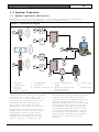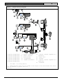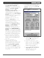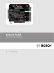
1
Security Escort
Installation and Setup
Guide
EN
Security Escort
Security Escort | Installation and Setup Guide |
2.0
Equipment Estimation: This
section serves as a guide to
estimating the equipment needed for a
bid, the location accuracy to expect,
and how to mount the receivers to
achieve that accuracy.
Agencies
Consult the documentation accompanying
each component for specific listings.
About This Manual
•
3.0 Installation Instructions: This
section provides an overview and
quick reference for the overall
installation of a Security Escort
System. Consult the Installation
Instructions that accompany each
individual Security Escort component
for specific installation and set-up
instructions for that component.
•
4.0 System Power-up and Debug: This
section includes information on
making the system “live” after all
components are installed and wired.
•
5.0 Testing and Troubleshooting :
This section provides procedures for
ensuring that the system is “live”
and functional. Also, a
troubleshooting guide is provided in
the event that some components do not
respond to the system.
General Information
The purpose of this manual is to
identify the components of the Security
Escort system, provide installation
instructions for those components as
well as the system as a whole provide
testing procedures for the system and
its components, and provide a
troubleshooting guide. The sections of
this manual are as follows:
•
1.0 System Overview: This section
provides a reference for estimating
and ordering components for a
Security Escort installation.
Attention is given to relevant
specifications of individual
components to assist an installer in
providing accurate bid estimation.
•
Bosch Security Systems | 1/09 | 33831E
EN | 2
•
Security Escort | Installation and Setup Guide |
•
Appendix: The Appendix provides
additional information and forms that
may be useful before and during
installation.
If you encounter any problems or
questions that are not covered in this
manual, contact Bosch Security Systems
Technical Support at the phone number
listed on the back page of this manual.
Safety Symbols and Their Meanings
Throughout this document, the following
symbols are used to alert the reader to
safety issues when installing or
operating the system:
This symbol informs the reader
of possible bodily injury if
procedures are not followed
exactly. The text accompanying
this symbol tells the reader
what he should or should not
do. For example, “ensure that
you are properly grounded
before opening the unit.”
This symbol alerts the reader
to possible equipment damage if
procedures are not followed
correctly. For example, “do not
connect the positive wire to
the negative terminal.”
Conflicts with Other Documents
In addition to this manual, the
installer is directed to review
installation instructions that accompany
individual components, and release
notes. In the event of a discrepancy
between the information provided in this
document, and the information provided
in a document accompanying a specific
component (or release notes), the
information contained in the
installation instructions or release
notes shall prevail.
Trademarks
Microsoft®, Windows, Windows NT®,
Windows 98, and Windows 2000 are either
registered trademarks or trademarks of
Microsoft Corporation in the United
States and/or other countries.
Bosch Security Systems | 1/09 | 33831E
EN | 3
Security Escort | Installation and Setup Guide | Table of
Contents
EN | 4
2.3.2 Indoor Receiver Installation .. 19
Table of Contents
1.0
System Overview................. 6
1.1
System Components Description... 6
1.2
Compatible Parts................ 7
1.3
System Components and
Specifications........................ 8
1.3.1 Central Console................. 8
1.3.2 SE485 Interface Adapter......... 9
1.3.3 EA500 Transponder............... 9
1.3.4 EA102 Receiver................. 10
1.3.5 EA120 Alert Unit............... 10
1.4
Transmitters................... 11
1.4.1 Personal Escort Transmitters... 11
1.4.2 SE2 Personal Transmitter....... 12
1.4.3 SE3 Subscriber Transmitter Family
............................... 12
1.4.4 SE3401 Point Tracking Transmitter
............................... 12
1.5
Cables......................... 13
1.5.1 C312: Transponder to ProxLink
Radio Module Cables............ 13
1.5.2 Master to Slave................ 13
1.5.3 Computer to SE485 (not supplied)
............................... 13
1.5.4 Battery Cables................. 13
1.6
Batteries...................... 13
1.6.1 E28629B, Special 3 Ah.......... 13
1.6.2 P334, Standard 7 Ah............ 14
1.6.3 D1218, Standard 17 Ah.......... 14
1.7
Enclosures..................... 14
1.7.1 AE1, Small Indoor Enclosure.... 14
1.7.2 AE3, Large Indoor Enclosure.... 14
1.7.3 AE100 Indoor Enclosure......... 14
1.7.4 AE101 Outdoor Enclosure........ 14
1.8
Miscellaneous.................. 14
1.8.1 Siren Strobe................... 14
1.8.2 TR1850 Transformer, 110 VAC to
18 VAC, 50 VA, 60Hz............ 14
1.8.3 E28666B Security Hex Driver.... 14
1.8.4 P335-10 Replacement Batteries.. 14
1.8.5 Holsters for SE2 Transmitters.. 14
1.8.6 SE112.......................... 15
1.8.7 CTS1-70 Enclosure Cover/Wall
Tamper......................... 15
2.0
Equipment Estimation........... 15
2.1
Location Accuracy.............. 15
2.2
Pre-Bid Equipment Estimation... 16
2.2.1 Initial Equipment Estimate..... 16
2.3
Pre-Construction Coverage
Verification Survey.................. 18
2.3.1 Verify Each Potential Receiver
Location....................... 18
Bosch Security Systems | 1/09 | 33831E
2.3.3 Outdoor Receiver Installation . 19
2.4
Post Construction Setup ....... 21
2.4.1 Testing the location accuracy of
an installation ............... 21
2.4.2 Improving the location accuracy
of an installation ............ 23
3.0
Installation Instructions ..... 25
3.1
Overview of Installation Process
.............................. 25
3.2
Run System Wiring ............. 25
3.2.1 General Guidelines ............ 25
3.2.2 Observe Established Standards . 26
3.2.3 SE485 Interface Wiring Notes .. 30
3.2.4 Transponder Wiring Notes ...... 30
3.2.5 Receiver Wiring Notes ......... 30
3.2.6 Alert Unit Wiring Notes ....... 30
3.3
Mounting the Enclosures ....... 30
3.3.1 AE1 Small Indoor Enclosure .... 30
3.3.2 AE3 Large Indoor Enclosure .... 31
3.3.3 AE100 Indoor Enclosure ........ 31
3.3.4 AE101 Outdoor Enclosure ....... 32
3.4
Mounting and Setting Up
Components .......................... 32
3.4.1 EA102 Receiver Installation ... 32
3.4.2 EA500 Transponder Installation 32
3.4.3 EA120 Alert Unit Installation . 34
3.4.4 ProxLink Setup ................ 36
4.0
System Power-up and Debug ..... 38
4.1
Initial System Configuration .. 38
4.2
Powering Up the System for the
First Time .......................... 38
5.0
Testing and Troubleshooting ... 40
5.1
Built-In Troubleshooting Aids . 40
5.2
Receiver ...................... 40
5.2.1 Jumpers ....................... 40
5.2.2 Test Mode ..................... 40
5.2.3 Receiver Spacing Mode ......... 41
5.3
Transponder ................... 41
5.3.1 Status LEDs ................... 41
5.3.2 Verifying Communications ...... 43
5.4
Troubleshooting Reference ..... 43
Appendix ............................ 47
Transponder Information Sheet ....... 47
Security Escort | Installation and Setup Guide | Table of
Contents
Figures
Figure 1: System Block Diagram........ 6
Figure 2: Determining the Number of
Indoor Receivers Required... 16
Figure 3: Determining the Number of
Outdoor Receivers Required.. 17
Figure 4: Receiver Spacing........... 18
Figure 5: General Wiring Diagram..... 27
Figure 6: Transponder to ProxLink
Wiring...................... 28
Figure 7: ProxLink to Central Console 29
Figure 8: AE1 Enclosure.............. 31
Figure 9: AE3 Enclosure.............. 31
Figure 10: AE100 Enclosure........... 31
Figure 11: Back of AE100 Enclosure... 32
Figure 12: Inside AE101 Enclosure.... 32
Figure 13: EA500 Mounting to AE1
Enclosure................... 33
Figure 14: EA500 Mounting to AE3
Enclosure................... 34
Figure 15: Mounting the EA120 to the
AE1 Enclosure............... 35
Figure 16: Mounting the EA120 in the
AE101 Enclosure............. 35
Figure 17: ProxLink Radio Module
Configuration............... 37
Figure 18: Current Transponder Status
Screen...................... 38
Figure 19: Receiver Configuration
Screen...................... 39
Figure 20: EA500 Diagnostic LEDs..... 41
Figure 21: EA501 Diagnostics LEDs.... 41
Tables
Table 1: Compatible Parts............. 7
Table 2: Models and Supported Users... 8
Table 3: SE2 Personal Transmitter
Features.................... 12
Table 4: SE3 Subscriber Transmitter
Features.................... 12
Table 5: Battery Amp Hours........... 13
Table 6: Wiring Guidelines........... 25
Table 7: Transponder - SE485 Wiring
Table....................... 26
Table 8: Jumper Operation............ 40
Table 9: Status LEDs................. 42
Table 10:Transponder Communications
with SE485 Bus.............. 43
Table 11: . Transponder Communication with
ProxLink Radio.............. 43
Table 12:EA500 Transponder Bus Faults 45
Table 13:EA102 Receiver Issues....... 45
Bosch Security Systems | 1/09 | 33831E
EN | 5
Security Escort | Installation and Setup Guide | 1.0
System Overview
EN | 6
1.0 System Overview
1.1
System Components Description
The Security Escort System consists of five basic components: transmitters,
receivers, alert units, transponders, and the central console.
Figure 1: System Block Diagram
2
1
6
3
4
by
D e tec ti o n S y s te m s , In c .
5
7
2
9
8
3
4
10
1 - Personal
4 - Transponder
transmitter
5 - Interface
2 - Outdoor
6 - Central console
receiver
3 - Indoor receiver
Transmitter: A miniature, hand-held
radio transmitter used to send either
a distress or a test signal. The
receivers are located throughout the
protected area and detect the radio
transmissions from transmitters.
Alert units: Siren/strobe units
activated in the event of an alarm.
Transponders: Devices that control
groups of receivers and alert units,
connected to them by wire. Each
transponder relays alarm and test
signals from its receivers to the
central console. In addition, the
Bosch Security Systems | 1/09 | 33831E
11
7 - Other transmitter
10 - Alert unit
types
11 8 - Security transmitter
Siren/strobe
9 - Spread spectrum
wireless link
Transponder tests for device and
wiring faults, and transmits problem
conditions to the central console.
Central console: A computer (plus an
optional backup and up to eight
optional workstations) which receives
alarm and trouble signals from the
transponders, analyzes the signals,
activates strobes and sirens on the
alert units, and produces a display
for the security dispatcher. Each of
these system elements is described
more fully in the sections that
follow.
Security Escort | Installation and Setup Guide | 1.0
System Overview
1.2
EN | 7
Compatible Parts
Table 1 indicates the parts available for inclusion in a Security Escort System.
Contact Bosch Security Systems Customer Service for up-to-date model numbers.
Table 1: Compatible Parts
Part Name
Electronics,
Components
Enclosures and
Housings
Cables
Software
Misc. Parts and
Accessories
EA500
EA102
EA120
SE485
SE3
Transmitters
SE2
Transmitters
SE3401
AE3
AE1
AE100
AE101
C311
C312
SE2005
SE2010
SE2050
SE2100
HOLST-LGB-SE2
HOLSTER-SE2
E28666B
TR1850
P335-10
E28629B
P334
D1218
SE112
CTS1-70
Description
Electronics for eight-bus transponder
Electronics for indoor or outdoor receiver
Electronics for indoor and outdoor alert unit
Interface between transponder and central console
Personal duress transmitter
Man-down, lanyard, supervisory, and duress
transmitter
Point tracking transmitter
Large [51.5 cm x 37.5 cm (20.25 in. x 14.75 in.)]
enclosure
Small [36.8 cm x 31.8 cm (14.5 in. x 12.5 in.)]
enclosure
Indoor receiver enclosure
Outdoor receiver enclosure
3 Ah or 7 Ah battery harness parallel expansion kit
Cables for transponder to ProxLink Radio Module
System software for up to 500 users
System software for up to 1000 users
System software for up to 5000 users
System software for up to 10000 users
Leather holster for SE2 Transmitters, large belt
loop [5.7 cm (2.25 in.)]
Leather holster for SE2 Transmitters, standard belt
loop [4.5 cm (1.75 in.)]
Security hex driver for receivers
Transformer
SE2 Replacement Batteries, ten pack of CR2, 3 VDC
lithium
3 Ah 12 V battery for outdoor alert unit
7 Ah 12 V battery for indoor alert unit
17 Ah 12 V battery
Portable test receiver with display
Enclosure cover/wall tamper for AE1 and AE3
Bosch Security Systems | 1/09 | 33831E
Security Escort | Installation and Setup Guide | 1.0
System Overview
1.3
For systems supporting more than
10000 users, contact Bosch Security
System Sales.
System Components and
Specifications
1.3.1 Central Console
Description
The central console consists of one or
two IBM PC compatible computers (and
up to eight additional workstations)
running the Security Escort software
within the Microsoft® Windows®
environment. One computer serves as
the master controller for the entire
Security Escort system. The second
slave computer serves as a back-up.
The slave computer can be used for
administrative functions such as
adding subscribers or performing
routine system tests without
interfering with the operation of the
main computer. The workstations can
perform all normal Security Escort
functions with the exception of
communicating with the Security Escort
transponders.
Software Overview
The central console contains all the
operating software and all the
databases required by the Security
Escort system. The installation and
maintenance portion of the Security
Escort software facilitates set-up and
modification of the system and
provides rapid diagnosis of system
problems. Usually only one person is
required. The system software also
continually monitors the status of
each transponder to ensure it
functions correctly.
Versions
There are several versions of the
software available. The number of
users the system supports defines each
version. Table 2 lists the available
models and the number of supported
users:
Table 2: Models and Supported Users
Model
SE2005
SE2010
SE2050
SE2100
User Base
500
1000
5000
10000
Note:
Bosch Security Systems | 1/09 | 33831E
EN | 8
Minimum System Requirements
Each computer in the central console
should be equipped with at least the
following features and components:
•
Processor: Pentium class processor
or better, 200 MHz or faster.
•
Operating system: Microsoft Windows
95, Windows 98, Windows NT® (4.0 or
later), or Windows 2000.
•
RAM: 16 megabytes of RAM minimum,
32 megabytes preferred, in Windows
95 or Windows 98. Windows NT or
Windows 2000 systems should have 64
megabytes of RAM.
•
Hard disk space: 1 gigabyte of hard
disk space should be available to
allow collection of historical
data.
•
Backup: External backup drive, such
as an Iomega or SyQuest Cartridge
Hard Disk for backup and history
storage.
•
Video: VGA (640 x 480) at 256
colors minimum, 800 x 600 high
color (16 bits) recommended, 1024 x
768 high color supported, true
color (24 bits) is also supported.
If displaying subscriber images,
high color (16 bits) or true color
(24 bits) should be used.
•
Modem: Optional V.32 bis (14.4),
V.34 (33.8), or V.90 (56.6) modem
for remote access and pager dialout. If the modem is external, an
additional serial port is required.
•
Sound: Any Windows compatible sound
system. One set of computer
speakers per computer.
•
Printer: Parallel port, dot matrix,
continuous forms, printer for alarm
output.
Security Escort | Installation and Setup Guide | 1.0
System Overview
•
Additional serial ports (if
needed): Any multi-port board fully
supported by Windows. A four-port
ISA serial port card made by
Digiboard, model AccelePort Xe,
part number 76000035. Required
four-port cable for DB25, part
number 76000008. Digiboard also
makes eight- and sixteen-port
solutions. They may be contacted at
www.digiboard.com.
Databases
•
Alarm reports: Each alarm is saved
as a record containing subscriber
data, time and date of alarm,
acknowledgment and silence times,
responding officer, problem
description, and action taken. The
alarm map can be reproduced and the
location text is displayed.
•
History: A complete chronological
history of all system actions,
tests, and alarms is recorded.
•
Operators: File of those authorized
to use the Security Escort system.
•
Subscriber: Complete record of all
subscriber data and current status,
low battery, and last test date and
time.
•
Transponders: System configuration
containing all installed equipment
and system interrelationships.
Other Specifications
•
Temperature range: 0ºC to +40ºC
(+32ºF to +105ºF)
•
Primary power: 120 VAC 900 W (two
computers, two monitors, and one
printer).
•
•
Backup power: 1200 VA UPS per
computer provides 45 min. to 1-hr.
backup. System should also be
backed up by an emergency generator
for extended blackouts (can be
shared with other emergency
equipment).
Pager: Pager support is included
and selected troubles can be
automatically sent to a service
pager.
Bosch Security Systems | 1/09 | 33831E
EN | 9
1.3.2 SE485 Interface Adapter
Description
The SE485 is an interface between the
pseudo RS-485 signal bus of the
Security Escort Transponder and the
Serial Bus (RS-232) of the Security
Escort central console. The SE485
allows multiple transponders to
interface into a single RS-232 port.
Due to changes made for transient
protection, transformer isolation, and
link busy detection, these signals are
not compatible with third party RS-485
interfaces.
Specifications
•
Dimensions: 13.5 cm x 8.5 cm x 30
cm
(5.375 in. x 3.3125 in. x 1.1875
in.).
•
Power Source: 9 VDC, 200 mA. An
included 120 VAC adapter to 9 VDC
or from the transponder 9 VDC
terminals.
•
Temperature range:
(+32°F to +149°F)
0°C to +65°C
1.3.3 EA500 Transponder
Description
The transponder is a device controller
for up to 64 devices; and any
combination of receivers and alert
units. The devices are connected to
the transponder by means of four-wire
buses; two for power and two for data.
There are eight buses and each bus is
capable of supporting up to eight
devices. The Security Escort system
supports up to 255 transponders.
Specifications
•
Compatible Enclosures:
-
Small indoor: AE1
-
Large indoor: AE3 (recommended)
•
Temperature range: -40°C to +65°C
(-40°F to +149°F)
•
Power Source: 18 VAC, 50 VA (can
use TR1850, 110 VAC to 18 VAC
transformer)
•
Battery backup: 12 VDC lead acid
battery
Security Escort | Installation and Setup Guide | 1.0
System Overview
•
•
Power output: 9 VDC output for
SE485 or for ProxLink Radio Module
power
-
•
•
•
Specifications
•
Driver outputs:
-
EN | 10
Enclosure:
-
Indoor: AE100 indoor enclosure
-
Outdoor: AE101 outdoor enclosure
Strobe: 500 mA solid state sink,
terminal switches to ground in
an alarm condition.
•
Siren: 500 mA solid state sink,
terminal switches to ground in
an alarm condition.
Temperature range: -40°C to +65°C
(-40°F to
+149°F)
•
Power source: 12 VDC, 25 mA
typical, 55 mA with horn sounding,
supplied from the transponder MUX
bus
•
Antenna type: Diversity antennas
protected within enclosures
Multiplex buses: eight multiplex
driver buses for power and
communication to receivers or alert
units
Communication interface to central
console: selectable SE485 or RS-232
Keyswitch input: Optional 47k EOL
resistor, supervised loop
1.3.4 EA102 Receiver
Description
The EA102 Receivers are located
throughout the grounds and building
interiors. Each receiver contains a
radio receiver to detect the
transmissions from transmitters.
Multiple receivers detect the same
transmission and send the signal
information to the transponder so the
system can identify the transmitting
device, transmitting information, and
location. The receiver also reports
housing tampering and radio jamming to
the transponder.
Indoor receivers are typically mounted
on inside walls and have one red and
one green LED. The green LED is used
to indicate a successful Test of a
personal transmitter. The red LED is
illuminated during alarms. Each
receiver contains a piezo-electric
horn that can be activated if the
receiver detected an alarm
transmission
Outdoor receivers are contained in
small weatherproof boxes typically
mounted on the sides of buildings and
on light posts. Outdoor receivers do
not have the visible red and green
LED’s. Outdoors, the strobe lights on
the alert units should be used to
acknowledge successful test and alarm.
Bosch Security Systems | 1/09 | 33831E
1.3.5 EA120 Alert Unit
Description
This is a control module that
communicates with the transponder on
the MUX Bus. The alert unit can be
used to activate strobe and siren
units or optional other switched
devices. The alert unit also reports
tampering, AC power loss, and backup
battery level to the transponder.
Specifications
•
Enclosures:
-
Indoor: AE1 small indoor metal
-
Outdoor: AE101 outdoor fiber
•
Temperature range: -40°C to +65°C
(-40°F to +149°F)
•
Power source: 18 VAC, 50 VA (can
use TR1850, 110 VAC to 18 VAC
transformer)
•
Battery backup: 12 VDC lead acid
battery
•
Driver outputs:
-
Power: 1 A maximum, intended as
the supply source for strobe and
siren
-
Strobe: 500 mA solid state sink,
terminal switches to ground in
an alarm condition
-
Siren: 500 mA solid state sink,
terminal switches to ground in
an alarm condition
Security Escort | Installation and Setup Guide | 1.0
System Overview
1.4
Transmitters
•
•
Unique ID Code: All Personal Escort
Transmitters contain a unique
identification that can be entered
into the central console System
Database. This allows the system to
only respond to appropriate users
and ignore unauthorized devices. It
also allows unique identification
of owner in database.
•
Local Piezo Sounder: All Personal
Escort Transmitters contain an
internal piezo sounder device. The
piezo is sounded during most types
of transmissions to indicate to the
user that the alarm or test event
was activated.
•
Duress Alarm (Manual Alarm): All
Personal Escort Transmitters allow
an alarm condition to be
transmitted by the user manually
activating the ALARM buttons.
•
Transmitter Test: All Personal
Escort Transmitters allow the user
to activate the transmitter to
perform a system test. This tests
that the system acknowledges the
transmitter, the receivers in the
area function, the transponder
communication functions, and the
particular transmitter ID are in
the central console database.
•
Man-Down: Some transmitters contain
an internal “tilt” switch that
monitors and transmits an alarm if
the transmitter is not in an
upright position.
•
Supervision: Some transmitters send
periodic transmissions, allowing
the system to monitor activity of
the transmitter and report failing
transmitters or missing
transmitters.
Bosch Security Systems | 1/09 | 33831E
Note:
Supervision transmissions do not
activate the local piezo sounder.
1.4.1 Personal Escort Transmitters
Note:
Not all features are available on
all transmitters.
EN | 11
•
Lanyard: Some transmitters contain
a “pull switch” that transmits an
alarm if the lanyard is pulled from
the transmitter unit.
•
Auto Tracking: When an alarm is
transmitted, the transmitter
continues to transmit periodically
for 15-min. following the alarm.
This allows the system to track a
moving transmitter that is
activated.
•
Silent Manual Alarm (“Security”):
This feature is available on
Security Transmitters. When the
duress alarm (manual alarm) is
activated by the user, there is no
local sounder turned on. This
allows users to transmit the alarm
silently.
•
Maintenance Transmitter: Used to
validate the system functions. By
performing a test, the receiver
indicates receptions by lighting
the green LED. Transmitting an
alarm lights the red LED. The
Maintenance Transmitters do not
activate a real system alarm, the
system uses the information for
diagnostic and test purposes only.
There is no auto tracking on the
Maintenance Transmitters.
•
Low Battery Indication: The battery
status is sent with each
transmission, the system tracks and
reports low battery devices.
Security Escort | Installation and Setup Guide | 1.0
System Overview
EN | 12
1.4.2 SE2 Personal Transmitter
Description
There are several versions of the SE2,
and these versions along with their
respective features are shown in Table
3:
Table 3: SE2 Personal Transmitter Features
Feature
Manual Duress Alarm
Manual Test
Man-Down
Supervision
Lanyard Snatch
Auto Tracking
Silent Manual Alarm
Low Battery Indication
Model
SE2S
9
9
9
9
SE2U
9
9
9
9
9
9
9
9
SE2M
9
9
9
9
9
9
Note:
Due to communications limitations
between the transponder and
receivers, a maximum of 200
supervised SE2 transmitters can be
handled in a Security Escort
system.
Specifications
•
Battery: User replaceable 3 V
lithium
•
Temperature range: -30ºC to +65ºC
(-22ºF to +150ºF)
1.4.3 SE3 Subscriber Transmitter
Family
Description
The SE3 Subscriber Transmitter is a
personal duress transmitter that
contains the Manual Duress Alarm,
Manual Test, and Auto Tracking
features.
SE2S-SN
9
9
9
9
9
9
9
9
9
SE2U-SN
9
9
9
9
9
9
9
Specifications
•
Battery: Two user replaceable 3 VDC
lithium coin cells (CR2025 size)
•
Temperature range: (-30ºC to +65ºC)
-22ºF to +150ºF
1.4.4 SE3401 Point Tracking
Transmitter
Description
The SE3401 Point Transmitter is a
magnetic and dry contact wireless
transmitter used for monitoring
assets.
The unit is equipped with an internal
reed contact for use with an external
magnet assembly (included), a cover
tamper switch and RF supervision. The
SE3401 also can accept a supervised
dry contact input from an external
device.
Specifications
•
Dimensions:
Table 4: SE3 Subscriber Transmitter
Features
-
Transmitter w/o Mounting Plate:
35 mm x 76.5 mm x 19 mm
(1.5 in. x 3.25 in. x .75 in.)
Feature
-
Mounting Plate:
35 mm x 76.5 mm x 3.2 mm
(1.5 in. x 3.25 in. x .125 in.)
Manual Duress Alarm
Manual Test
Auto Tracking
Silent Manual Alarm
Low Battery Indication
SE3U
9
9
9
9
Model
SE3S
9
9
9
9
9
Bosch Security Systems | 1/09 | 33831E
•
Operating Temperature: (-20°C to
+65°C )
(-4°F to +150°F)
Security Escort | Installation and Setup Guide | 1.0
System Overview
•
•
Operating Voltage: Supplied by a 3
VDC lithium battery.
Battery Life: Up to five years
under normal usage with the
recommended battery types. Higher
usage decreases battery life.
EN | 13
1.5.3 Computer to SE485 (not supplied)
Note:
This cable is not supplied by Bosch
Security Systems.
Description
This cable connects the SE485
Interface to the serial port of the
Security Escort central console.
•
Recommended Battery Types: Duracell
DL123A, Energizer EL123AP, or
Panasonic CR123A.
•
Compatible Receivers: EA102A-304
•
•
Maximum length: 15 m (50 ft.)
Options: Magnet-RF-10 Assembly
(supplied in packages of ten)
•
Connectors: The SE485 uses a DB25
pin male connector, the other end
depends on the computer serial port
connector. The wiring is a
straight-through serial cable.
1.5
Cables
1.5.1 C312: Transponder to ProxLink
Radio Module Cables
Description
Two cables - one cable provides power
from the Transponder to the ProxLink
Radio Module; the other cable provides
data transfer between the Transponder
and ProxLink Radio Module (nonstandard cable).
Specifications
•
•
Power
-
Length: 1.8 m (72 in.)
-
Connectors: DC power plug at one
end (negative contact on
outside, positive contact in
center), flying leads on the
other end
Specifications
1.5.4 Battery Cables
Description
C311: This kit is used to parallel
connect two small-lug-size batteries
to increase backup battery capacity.
1.6
Batteries
Bosch Security Systems recommends that
you supply your own 12 V lead-acid
batteries for system component back-up
time as needed for your installation.
However, some of the standard battery
sizes can be supported. See Table 5
for the required amp hours of the
batteries for your installation.
Table 5: Battery Amp Hours
Data
-
Length: 76 cm (30 in.)
-
Connectors: Standard male DB9
connectors at each end, wired
special for data link. NOT a
standard cable.
1.5.2 Master to Slave
Note:
This cable is not supplied by Bosch
Security Systems.
Description
Null modem cable connecting the two
computers running the central console
software.
Specifications
•
Maximum Length: 15 m (50 ft.)
•
Connectors: To be compatible with
your PC’s requirements.
Bosch Security Systems | 1/09 | 33831E
Number
of
Hours
4
8
12
24
Amp hours (Ah) Required per
Number of Receivers
8
16
32
64
2.3
4.6
7.0
14
3.5
7.0
10.3
20.6
5.7
11.4
17.0
34.0
10.2
20.4
30.6
----
1.6.1 E28629B, Special 3 Ah
Description
Special size used especially for the
outdoor alert unit.
Security Escort | Installation and Setup Guide | 1.0
System Overview
EN | 14
Specifications
Specifications
•
Dimensions: 6.3 cm x 13.3 cm x 6.3
cm
(2.5 in. x 5.25 in. x 2.5 in.)
Dimensions: 22.9 cm x 17.8 cm x 14.4
cm
(9 in. x 7 in. x 1.75 in.)
•
Amp-hours: 3 Ah
•
Voltage: 12 VDC
1.6.2 P334, Standard 7 Ah
Specifications
•
Dimensions: 9.5 cm x 15.2 cm x 6.3
cm
(3.75 in. x 6 in. x 2.5 in.)
•
Amp-hours: 7 Ah
•
Voltage: 12 VDC
1.7.4 AE101 Outdoor Enclosure
Description
This enclosure houses the receiver or
alert unit. It is suitable for outdoor
installation. The receiver’s LEDs and
sounder cannot be used in this
enclosure. A mounting kit for the
electronic components is included.
Specifications
Dimensions: 37.5 cm x 32.4 cm x 8.9 cm
(14.75 in. x 12.75 in. x 3.5 in.)
1.6.3 D1218, Standard 17 Ah
1.8
Specifications
1.8.1 Siren Strobe
The armored siren with strobe can be
purchased through third-party vendors.
Bosch Security Systems recommends
Amseco Armored Siren with Strobe
(model number SSX-51S).
•
Dimensions: 16.5 cm x 17.8 cm x 7.6
cm
(6 1/2 in. x 7 in. x 3 in.)
•
Amp-hours: 17 Ah
•
Voltage: 12 VDC
1.7
Enclosures
1.7.1 AE1, Small Indoor Enclosure
Description
The AE1 Enclosure is suitable only for
indoor installation. A mounting kit
for the electronic components is
included.
Miscellaneous
1.8.2 TR1850 Transformer, 110 VAC to
18 VAC, 50 VA, 60Hz
Description
The TR1850 Transformer provides AC
power to the transponder and alert
unit.
Specifications
•
Input: 110 VAC, 60 Hz
Specifications
•
Output: 18 VAC, 50 VA max.
Dimensions: 36.8 cm x 31.8 cm x 8.6 cm
(14.5 in. x 12.5 in. x 3.375 in.)
1.8.3 E28666B Security Hex Driver
1.7.2 AE3, Large Indoor Enclosure
Description
The AE3 is suitable only for indoor
installation. A mounting kit for the
electronic components is included.
Description
The E28666B Security Hex Driver is the
tool required to mount and maintain
the indoor receiver enclosures.
1.8.4 P335-10 Replacement Batteries
Dimensions: 52.7 cm x 38 cm x 10.8 cm
(20.75 in. x 15 in. x 4.25 in.)
Description
The P335-10 is a ten-pack of lithium
replacement batteries for the SE2
Transmitters.
1.7.3 AE100 Indoor Enclosure
1.8.5 Holsters for SE2 Transmitters
Description
The AE100 Indoor Enclosure houses the
receiver. It is suitable only for
indoor installation.
Description
•
HOLSTER-SE2: Leather holster for
4.4 cm
(1.75 in.) security belt.
Mounting screws: Security design,
require E28666B security hex driver
•
HOLST-LGB-SE2: Leather holster for
5.7 cm
(2.25 in.) security belt.
Specifications
Bosch Security Systems | 1/09 | 33831E
Security Escort | Installation and Setup Guide | 2.0
Equipment Estimation
EN | 15
1.8.6 SE112
Description
Custom Test Receiver with LCD display.
1.8.7 CTS1-70 Enclosure Cover/Wall
Tamper
Description
The CTS1-70 can be installed in AE1
and AE3 Enclosures for use as a cover
tamper switch, a wall tamper switch or
both (two required). The CTS1-70 is
intended for connection to normally
closed tamper or supervised circuits,
and operates as a normally closed
device when the plunger is depressed.
Specifications
Contacts are rated 0.3 A, 100 VDC,
maximum.
2.0 Equipment Estimation
A Security Escort system installation
consists of three major steps.
1. The pre-bid equipment estimation
2. The pre-construction coverage
verification survey
3. The post construction setup
The Security Escort Receivers work
effectively in a wide variety of
installations and can be placed with
confidence provided these installation
requirements are met. Therefore, at
the pre-bid stage, it is acceptable to
estimate the required equipment. To
ensure proper coverage after proposal
acceptance, potential receiver
locations can be verified using a
standard receiver in test mode or the
portable test receiver before
construction begins.
2.1
Location Accuracy
The Security Escort system provides
quick response to a duress call by
dispatching a responding individual to
an area without adding additional
delay to their response to that duress
call.
The Security Escort system uses radio
frequency (RF) for alarm
transmissions. This is significant
because it prevents normal
construction from blocking the signal
and helps to eliminate dead spots
where the alarm cannot be heard. The
fact that RF energy passes through
normal construction prevents Security
Escort from locating an alarm with
100% certainty to a specific side of a
wall. Alarms originating at or near
building walls are typically indicated
within 7.5 m (25 ft.) of the actual
location; however, there may be times
when the computed location may appear
to be on the other side of the wall.
The Security Escort system was
designed to provide a computed alarm
location typically within 7.5 m
(25 ft.) of the actual location when
indoors and a computed alarm location
typically within 15 m (50 ft.) of the
actual location outdoors. Any
deviation from the following
installation guidelines degrades the
computed location accuracy. Use the
following installation guidelines, to
achieve these results.
Bosch Security Systems | 1/09 | 33831E
Security Escort | Installation and Setup Guide | 2.0
Equipment Estimation
2.2
Pre-Bid Equipment
Estimation
The pre-bid equipment estimation is
performed prior to bidding the
installation. At this point, it must
be determined what type of coverage is
desired, and where the coverage is
required. For example, the amount of
equipment required for a full-coverage
(indoor and outdoor) system in a
multi-building application is greater
than an installation that requires
outdoor only coverage. The customer
should be consulted and the areas of
most concern should be given special
consideration.
2.2.1 Initial Equipment Estimate
Number of Indoor Receivers
To estimate the number of indoor
receivers, first read Section 2.3.2
Indoor Receiver Installation. Assume
the receivers are placed on a grid
with a maximum spacing of 25 m (80
ft.) between receivers for standard
construction. In multi-floor
applications the receivers on each
floor must be placed directly above
the receivers on the floor below (this
is required for proper floor-to-floor
location).
For example, to determine the number
of receivers required to protect a
building of standard construction of
60 m x 30 m (200 ft. x 100 ft.) and
four floors:
EN | 16
1. To determine the number of
receivers in each direction, divide
each dimension of the building by
25 m (80 ft.), drop the remainder,
and add 1.
For example:
•
60 m/25 m = 2.4, becomes 2, add
1 = 3
(200 ft./80 ft. = 2.5, becomes
2, add 1 = 3)
•
30 m/25 m =1.2, becomes 1, add 1
= 2
(100 feet/80 feet =1.25, becomes
1, add 1 = 2)
2. To determine the number of
receivers required per floor,
multiply the number of receivers in
one direction by the number of
receivers in the other direction:
(3 times 2 = 6) 6 receivers per
floor
3. To determine the total number of
receivers, multiply the number of
receivers per floor by the number
of floors:
(6 times 4 = 24) 24 receivers for
the building
Each floor would require 6 receivers,
resulting in a total of 24 receivers
to protect this building.
For the best location accuracy,
consistent receiver spacing is
important. Do not place receivers
significantly closer in one section of
a building than another section.
Figure 2: Determining the Number of Indoor Receivers Required
60 m
(200 ft.)
25 m
(80 ft.)
25 m
(80 ft.)
1
1 - Receivers (6)
Bosch Security Systems | 1/09 | 33831E
30 m
(100 ft.)
Security Escort | Installation and Setup Guide | 2.0
Equipment Estimation
Number of Outdoor Receivers
To estimate the number of receivers,
first read Section 2.3.3 Outdoor
Receiver Installation. Assume a
maximum receiver spacing of 90 m (300
ft.) between receivers, in both
directions, for receivers that are not
within 30 m (100 ft.) of a building
with inside coverage. Receivers within
30 m (100 ft.) of a building should be
spaced the same as receivers in the
building (spacing the outside
receivers at a somewhat larger spacing
is acceptable in most cases).
EN | 17
An outside area directly between two
buildings with inside protection needs
no additional receivers if the
buildings are 90 m (300 ft.) or less
apart. If the buildings are more than
90 m (300 ft.) apart the outside
receivers should evenly spaced between
the buildings. Make sure the standard
90 m (300 ft.) spacing is not
exceeded. For outside spacing adjacent
to a covered building, start the 90 m
(300 ft.) spacing at the building
wall.
Figure 3: Determining the Number of Outdoor Receivers Required
30 m
(100 ft.)
by
y
b
by
y
b
1
by
30 m
(100 ft.)
2
y
b
by
by
y
b
by
by
y
b
by
by
by
3
y
b
90 m
(300 ft.)
y
b
y
b
y
b
y
b
90 m
(300 ft.)
1 - Receivers
2 - Building 1
Allowance for Special Coverage
Requirements
For purposes of the bid, the number of
receivers estimated should be
increased by 5% to allow for special
coverage considerations and RF problem
areas.
Number of Transponders
Assume one transponder per building
for indoor installations. If wiring
can be run from other buildings or
from outdoor receivers, they can be
connected to one transponder. Never
exceed the total number of 64 devices
(receivers and alert units) per
transponder. All outside wiring must
be under ground or in metal conduit.
Bosch Security Systems | 1/09 | 33831E
by
by
90 m
(300 ft.)
3 - Building 2
Number of Receiver and Alert Units per
Multiplex Bus
Although each bus can handle eight
receivers and alert units, it is a
good idea to leave some addresses
available on each bus to allow for
future expansion. For systems with a
high number of supervised
transmitters, see Section 3.2.4
Transponder Wiring Notes.
Multiplex Bus Wire
The multiplex bus should be wired with
four conductor 1.2 mm (18 AWG) wire.
The wire should not be paired or
shielded. In the United States this is
the same as fire system wire, except
it should not be red.
Security Escort | Installation and Setup Guide | 2.0
Equipment Estimation
Number of Alert Units
The number of alert units is
determined by each system’s
requirements. In general, enough alert
units should be installed to be heard
and seen from all outdoor locations of
protection. Remember, even in a silent
system, alert units can be used
outside to provide test feedback.
Horn/strobe units should be mounted in
predictable locations to make them
easy to identify by subscribers. Alert
units are not required indoors because
the indoor receiver provides alarm and
test feedback. Each transponder drives
one siren and one strobe if they are
less than 15 m (50 ft.) from the
transponder.
It is a good idea for each protected
parking lot to have a siren/strobe
near it.
2.3
Pre-Construction Coverage
Verification Survey
The pre-construction coverage
verification survey is performed after
the bid is accepted and before
construction begins. It is done to
determine the location of each
receiver. Each receiver location
should be checked using a standard
receiver in the test mode.
2.3.1 Verify Each Potential Receiver
Location
Using a standard receiver in Receiver
Spacing Mode
EN | 18
Receiver Spacing Mode is enabled with
Jumper P5 in place (Jumper P4 removed)
on a standard receiver (see the EA102
Receiver Installation Instructions).
This mode is exactly the same as the
Test Mode, except only transmissions
with an adequate receive margin are
sounded. This indicates the maximum
acceptable spacing of receivers. Use
the following procedure to test the
spacing of receivers:
1. Mount the first receiver. Put
jumpers P1, P2, P3, and P5 in
place, remove all other jumpers.
Power the receiver from a 9 VDC or
12 VDC source.
2. Take the second receiver and a
transmitter a distance away from
the first receiver.
3. Activate the transmitter.
4. If Receiver 1 sounds the test beep,
Receiver 2 is within range. Repeat
this test until Receiver 1 no
longer sounds the test beeps. Move
back to the last location where
Receiver 1 received the test beeps.
This location marks the maximum
spacing between receivers. The
distance between receivers should
not exceed 25 m (80 ft.) indoors
and 90 m (300 ft.) outdoors. Mount
Receiver 2 at this location or
closer to Receiver 1.
Note:
Do not use the Test Mode (Jumper
P4) to determine receiver spacing.
Figure 4: Receiver Spacing
1
2
1 - Receiver
point
2 - Receiver
3 - Receiver
4 - Receiver
3
4
1 stops sounding the test beeps when Receiver 2 is moved past this
1
2 at maximum range
2 beyond maximum range
Bosch Security Systems | 1/09 | 33831E
Security Escort | Installation and Setup Guide | 2.0
Equipment Estimation
Using a Standard Transponder,
Receivers, and Laptop Computer to
Determine Receiver Location
Note:
System software and an area map
must be installed on a laptop
computer to use this method.
A standard transponder with long
multiplex wires connected to standard
receivers can be used to see actual
alarm location before the receivers
are placed. Place the receivers in the
proposed locations wired back to the
transponder. Program the receivers
with their locations in the
transponder database. Using the
maintenance transmitter and the
maintenance alarm database, activate
alarm transmissions within the area
surrounded by the temporarily placed
receivers. Verify that the location
accuracy is acceptable at all points
of concern. If not acceptable move the
receivers, update the receiver
location in the transponder database,
and retest. Do not test outside of the
last receiver in any direction, as
this gives incorrect locations. Repeat
this test in all areas of different
construction and concern at the site.
•
Indoor receivers must be mounted in
a evenly spaced grid no more than
25 m (80 ft.) apart.
•
Indoor receivers must be mounted
1.5 m to 1.8 m (5 ft. to 6 ft.)
above the floor. This is true even
if this is a single story building.
Do not mount receivers above the
ceiling or in roof rafters.
•
In multistory buildings, the
receivers must be mounted directly
above the receivers on the floor
below. The same number of receivers
must be used on each floor level.
If you meet all of the indoor
installation guidelines, you can
expect the computed location to
indicate the correct floor about
95% of the time.
•
Receivers must not be mounted
within 30 cm (1 ft.) of any metal
object, including wire mesh, metal
foil, metal pipe, and HVAC ducting
in walls.
Bosch Security Systems | 1/09 | 33831E
Take care that large metal objects
do not shield a receiver from a
protected area. For example; metal
staircases, metal food serving
lines, metal walls, lead lined
walls, metal roofs, wire mesh in
walls, walk-in freezers, and
refrigerators.
For the best indoor and outdoor
location or an indoor only system.
•
Mount the indoor receivers on the
recommended 25 m (80 ft.) grid,
with the last row of indoor
receivers on the outside wall of
the building. Do this even if the
building is less than 25 m (80 ft.)
wide or long.
•
There should be a receiver at each
outside corner of a building.
Handling two protected buildings
sharing a common wall with floor
levels that do not match
•
Ask the customer which building has
areas of greater concern and favor
the recommended mounting heights in
that building.
•
The recommended 25 m (80 ft.)
maximum indoor spacing grid should
be maintained throughout both
buildings as if the wall in
question was not there. Mounting
heights only for those receivers at
or near (within 6 m [20 ft.]) the
wall in question should be
affected. Mounting heights for all
other receivers in the buildings
must follow the indoor
recommendation. Mark the
recommended mounting height for
receivers on the higher floor level
and also mark the recommended
mounting height for receivers on
the lower floor level. Mount the
receiver at its normal grid
location midway between these two
heights, but not above the ceiling
level of the lower floor.
2.3.2 Indoor Receiver Installation
•
EN | 19
2.3.3 Outdoor Receiver Installation
•
Outdoor receivers must be mounted
in an evenly spaced grid no more
than 90 m (300 ft.) apart.
•
Outdoor receivers must be mounted 3
m (10 ft.) above the ground.
Security Escort | Installation and Setup Guide | 2.0
Equipment Estimation
•
•
Receivers must not be mounted
within 30 cm (1 ft.) of any metal
object, including fences, metal
walls, and walls with wire mesh. If
a receiver is mounted on a metal
fence, that fence should be
grounded (not floating or insulated
from the ground) and the receiver
should be spaced 30 cm (1 ft.) from
the fence and 3 m (10 ft.) above
the ground.
Take care that large metal objects
do not shield a receiver from a
protected area. For example metal
fences, metal staircases, metal
buildings, power transformers, and
metal roofs.
•
Receiver locations should be below
building overhangs and eaves as
these can shield the areas below
them.
•
Receivers should have a clear line
of sight of the protected area.
Take care where the ground is hilly
or uneven. Make sure there are no
areas and low spots where several
receivers cannot hear the signal.
Transition Areas between Indoor and
Outdoor Areas
•
An outside area directly between
two buildings with complete indoor
protection needs no additional
receivers between the buildings, if
they are 90 m (300 ft.) or less
apart.
•
When protecting an outside area
directly between two buildings with
complete indoor protection that are
more than 90 m (300 ft.) apart,
evenly space a row of outside
receivers evenly between the
buildings. Make sure the receiver
row does not exceed the standard 90
m (300 ft.) spacing from the
buildings. The spacing between
receivers in that row should be
about the same as the spacing for
the receivers in the buildings.
•
Indoor receivers should be no more
than 25 m (80 ft.) apart and
outdoor receivers should be no more
that 90 m (300 ft.) apart. Both of
these recommendations work well in
their respective areas. However, if
a building is adjacent to an
outdoor area, that building has a
greater density of receivers and,
therefore, has a tendency to pull
Bosch Security Systems | 1/09 | 33831E
EN | 20
the computed location towards it.
To counteract the building tendency
to pull the location, consider the
following special cases:
-
If the outdoor area adjacent to
the building is wide open and
the customer is not concerned
about reduced location accuracy
in this area, then nothing
special needs to be done. Follow
the normal indoor and outdoor
recommendations.
-
The building is near the
boundary of the protected area,
with or without a fence at the
boundary. The receivers in the
building should be placed at the
recommended 25 m (80 ft.)
spacing. The receivers at the
boundary of the protected area
near the building should be
spaced about the same as those
in the building, approximating
the same grid as used in the
building.
-
The building is adjacent to a
large protected outdoor area
that extends for more than 90 m
(300 ft.) from the building. The
receivers in the building should
be placed at the recommended 25m
(80 ft.) spacing. The receivers
in the large protected outdoor
area should be placed on the
normal 90 m (300 ft.) grid
except for the first row of
receivers adjacent to the
building. This first row of
outdoor receivers in the
transition area should “split
the difference” between the
indoor and outdoor spacing at
about 60 m (200 ft.).
Boundary Areas at the Outer Edge of
the Protected Area
The system cannot locate an alarm past
the last receiver at the boundary of
the protected area. Therefore the last
row of receivers must be at or past
the end of the protected area.
Security Escort | Installation and Setup Guide | 2.0
Equipment Estimation
2.4
Post Construction Setup
2.4.1 Testing the location accuracy of
an installation
Note:
Before doing any of the following
testing, it is important to verify
that every receiver in the system
is functioning correctly using the
procedure described in this guide.
Additionally, every receiver must
be programmed in the transponder
database with its actual physical
location and floor level. It is
also important that receivers
physically stacked directly above
one another on floors of a building
are also located at the same X and
Y coordinates in the database.
There are three methods you can use to
verify the location accuracy of an
installed system, using a standard
Subscriber Transmitter or a
Maintenance Transmitter. Repeat the
chosen process throughout all
protected areas. Ask the customer for
the areas where they have special
concern and devote extra attention to
those areas, since the customer is
likely to be more critical in those
areas.
Remember the intent of the Security
Escort system is to dispatch a
responding individual to an area that
does not add additional delay to their
response to that duress call.
Therefore the computed location should
be considered to be in error only when
it adds unacceptable additional time
to the alarm response.
During testing, it is helpful to see
which receivers are involved in the
alarm response and the relative
reception level they reported. To
display the receivers, select
Utilities Menu → Security
Preferences. Make sure the No Receiver
icon checkbox is not checked and click
the Save button. Select from the Setup
Menu → System Preferences → If Show
Test Levels → Show Maintenance Levels
are checked, the relative reception
level is shown in the receiver icons;
otherwise, the floor number is shown.
Bosch Security Systems | 1/09 | 33831E
EN | 21
When testing with any of the following
methods, the transmitter must be used
exactly as it is used in normal
operation. A transmitter designed to
be belt mounted or used in a holster
must be in its normal mounting
attitude and be worn on the belt of
the individual originating the test
transmissions. Handheld transmitters
must be held in the hand about waist
high, never above the head.
1. Using a standard subscriber
transmitter
a. This method requires two people
with radio contact between them.
One person operates the computer
running the Security Escort
software and the other takes the
Subscriber Transmitter to the
area to be tested.
b. Press the alarm on the
transmitter and remain at the
spot where you transmitted.
c.
The computer operator
acknowledges the alarm and
accurately describes the
computed location over the
radio. The individual with the
transmitter should confirm the
reported location or describe
over the radio the actual
location. Either individual must
record all discrepancies,
including the actual and
computed locations.
We recommend using a map or
floor plan and drawing an arrow
from the actual alarm location
to the reported location. It is
also helpful if all successful
alarm locations are marked with
a P (passed), then the alarm can
be reset from the computer
screen.
d. For areas where there are alarm
location problems, try facing in
different directions in the same
spot. Also generate additional
alarms from different spots to
fully understand the extent of
the problem. You should generate
alarms in areas adjacent to the
area with the problem to see if
they are also affected.
Security Escort | Installation and Setup Guide | 2.0
Equipment Estimation
2. Using a Maintenance Transmitter
with only one person
a. The Security Escort software
retains the last 50 maintenance
alarm locations. Make sure you
are the only one using a
Maintenance Transmitter on site,
buddy check is off, and that you
limit yourself to a maximum of
50 maintenance alarms per
sequence.
b. Synchronize the time on your
watch to the computer. Carry a
detailed map or floor plan of
the area to be tested that you
can write on.
c.
Take the Maintenance Transmitter
to the area to be tested. Press
the alarm on the transmitter and
accurately mark the spot on the
map where you transmitted with a
“1” (for the first
transmission). Also record the
time of the first transmission
only.
d. Continue to the next location,
transmit and mark that spot on
the map with a “2.” Repeat the
process throughout the area to
be tested, being sure not to
exceed 50 alarm transmissions
and making sure that at least
10-sec. elapse between
transmissions.
e. When finished, return to the
computer and select File →
Maintenance Alarm Database.
Scroll through the alarm list to
find the alarm that matches the
time of your first transmission.
This is the maintenance alarm
that you marked as “1” on your
map.
f.
Confirm that the actual location
from the map matches the
reported location.
Bosch Security Systems | 1/09 | 33831E
EN | 22
g. If the actual location differs
from the reported location, draw
an arrow on the map from the
actual location to the reported
location. Press the up arrow
once to go to the next alarm.
Compare the locations, drawing
an arrow to the reported
location if they differ. Repeat
this procedure for all points on
your map, making sure that the
points on the map stop when you
run out of entries in the
scrolling list on the computer
screen. Otherwise, the points on
the map and the screen are out
of sync and the errors on your
map are incorrect and
misleading.
h. For areas where there were alarm
location problems, you may want
to repeat the above process
facing in different directions
from the same spot. This
generates additional alarms from
different spots in the problem
areas to fully understand the
extent of the problem.
i.
You should also generate alarms
in areas adjacent to the area
with the problem to see if they
are also affected.
3. Using a Maintenance Transmitter
with two people
a. The two people must have radio
contact between them. One person
operates the computer running
the Security Escort software and
the other takes the Maintenance
Transmitter to the area to be
tested.
b. At the computer select File →
Maintenance Alarm Database. Make
sure the top item in the
scrolling list is selected.
Security Escort | Installation and Setup Guide | 2.0
Equipment Estimation
c.
Press the alarm on the
transmitter and remain at the
spot where you transmitted. At
the computer, observe the alarm
and accurately describe the
computed location over the
radio. The individual with the
transmitter should confirm the
reported location or describe
the actual location over the
radio. Either individual must
record all discrepancies,
including the actual and
computed locations. We recommend
using a map or floor plan and
drawing an arrow from the actual
alarm location to the reported
location. It is also helpful if
all successful alarm locations
are marked with a P (passed).
area. Generally, this is a bad
approach. If the system was
properly designed using the
recommended grid layout, adding
extra receivers in any area of the
grid distorts the response in
adjacent areas and floors. While it
may seem to fix the problem area,
typically, it creates more problems
in adjacent areas. The exception is
when an area is shielded by
something such as wire mesh in the
walls that prevent the RF
transmitted signal from passing
through. Additional receivers might
need to be added in the shielded
area to insure that all alarm
transmissions are heard.
•
Verify the location of the
receivers in the transponder
database matches the physical
location and the receivers are
indicated at the correct floor
level. It is also important that
receivers physically stacked
directly above one another on
floors of a building are also
located at the same X and Y
coordinates in the database.
•
Try changing the transponder
database location of receivers (not
the actual physical location) one
at a time while testing the alarm
location response, using one of the
testing methods above. For example,
if alarms are getting pulled
outside a building in one area,
move the closest receiver (in the
transponder database) to that area
a little further into the building
and retest. If the area can be
corrected using this method, verify
the surrounding areas to make sure
they were not adversely affected.
It is generally better if the
correction is done in small steps
while verifying the adjacent areas,
rather than trying to correct the
entire error in one step.
•
Version 2.03 and higher of the
Security Escort software allows
individual receiver sensitivity to
be set in the transponder database.
Receivers can be adjusted from 50%
to 149% of their normal
sensitivity. No physical receiver
changes or upgrades are required.
d. For areas where there are alarm
location problems, try facing in
different directions from the
same spot.
e. Generate additional alarms from
different spots to fully
understand the extent of the
problem.
f.
You should generate alarms in
areas adjacent to the area with
the problem to see if they are
also affected.
Reviewing potential problem areas
Review the potential problem areas on
the maps with the customer to see
which areas cause them concern and
which areas they consider acceptable.
If the customer considers an area
acceptable, it is typically not worth
spending additional time trying to
improve the location accuracy in those
areas.
2.4.2 Improving the location accuracy
of an installation
Once we identify areas needing
improvement, what are the options to
improve the computed location
accuracy?
Note:
All changes using the following
steps potentially change the
computed locations for all alarms
at or around the changed area.
After any change is made the entire
vicinity around the changed area
must be verified.
•
Typically, the first thought is to
add more receivers in the problem
Bosch Security Systems | 1/09 | 33831E
EN | 23
Security Escort | Installation and Setup Guide | 2.0
Equipment Estimation
•
•
Try changing the transponder
database sensitivity of receivers
one at a time while testing the
alarm location response, using one
of the testing methods above. For
example, if alarms are being pulled
towards a particular receiver,
lower its sensitivity in 10%
increments and retest. If the area
can be corrected using this method,
verify the surrounding areas were
not adversely affected. It is
generally better if the correction
is done in small steps while
verifying the adjacent areas,
rather than trying to correct the
entire error in one step.
With Version 2.03 and higher of the
Security Escort software, there are
five different location algorithms
that can be selected on an
individual receiver basis in the
transponder database: classic
(original Security Escort
algorithm), linear, low pull,
medium pull, and strong pull. By
default when a receiver is set for
outside or tunnel, it uses the
linear algorithm and all other
receivers use the low pull
algorithm. The receiver that most
strongly hears the alarm
transmission determines the
algorithm used for this alarm.
Changing the transponder database
algorithm setting for a receiver
only affects the location when the
alarm is close to this receiver and
it most strongly hears the alarm.
Change the transponder database
algorithm setting for a receiver
and test in its area, using one of
the testing methods above. The
stronger the pull the more the
alarm is pulled towards the
receiver, with linear having no
extra pull. Verify the surrounding
areas to make sure they are not
adversely affected.
Bosch Security Systems | 1/09 | 33831E
EN | 24
•
With Version 2.03 and higher of the
Security Escort software, the five
different location algorithms can
individually limit how close other
receivers must be to the level of
the receiver hearing the alarm the
best, before they are included in
the alarm. Classic (original
Security Escort algorithm), linear,
low pull, medium pull, and strong
pull each have a separate setting.
By adjusting this setting you can
control if distant receivers with
low receive levels are considered
in the alarm calculation.
•
With Version 2.03 and higher of the
Security Escort software, you can
add virtual receivers in the
transponder database. A virtual
receiver is added at one of the 64
points allowed per transponder.
However, there is no physical
hardware used. The virtual receiver
is intended to compensate in cases
where there is a receiver
imbalance. For example, if a
building with a dense population of
receivers is adjacent to a fence
with few receivers and an alarm
occurs between them; the alarm
location may pull towards the
building. The virtual receiver
refers to other physical receivers
that must be on the same
transponder. If both the referred
receivers receive an alarm
transmission, the virtual receiver
added to the alarm as if it was a
physical receiver hearing the alarm
at the average receive level of the
two reference receivers.
The virtual receiver’s location and
sensitivity may be adjusted the
same as a physical receiver. After
a virtual receiver is added, verify
the surrounding areas to make sure
they are not adversely affected. In
no event should a virtual receiver
be utilized as a cost savings
measure to avoid the installation
of an actual receiver.
Security Escort | Installation and Setup Guide | 3.0
Installation Instructions
The individual components are set up
and their addresses recorded.
3.0 Installation
Instructions
3.1
Note:
Use the Transponder Information
Sheet, located in the Appendix of
this document, to keep track of
receiver and alert unit addresses
and location for programming the
Transponder Database.
5. The recorded addresses are entered
into the central console and the
system is brought on-line.
6. The system is tested and tuned up
as needed.
Overview of Installation
Process
This section includes information
about the installation and setup of
the individual components and system
wiring. It is recommended that the
installation instructions that
accompany each specific component be
consulted prior to beginning any phase
of the installation.
A typical installation proceeds in the
following order:
1. The Site Survey is completed,
indicating the proposed location of
each component.
2. Wiring runs to all of the proposed
component locations and the central
console.
3. Empty enclosures are installed as
specified in the Site Survey.
4. The components are secured inside
the enclosures and connected to the
previously run wiring.
Table 6:
Alert Unit
3.2
Run System Wiring
3.2.1 General Guidelines
After the site survey and special preconstruction verifications are
completed, the wiring can be run
between the proposed locations of the
system components and the central
console. See specific installation
instructions accompanying each
component for wiring details. Table 6
indicates the specifications for the
wiring.
Wiring Guidelines
Application
From
To
Transponde Transforme
r
r
Alert unit
Alert Unit
EN | 25
Diagram
Reference*
1
2
Gauge
1.5 mm
(16 AWG)
1.2 mm
(18 AWG)
Conductor
s
2
4
Maximum
Distance
15 m
(50 ft.)
900 m
(3000 ft.)
per bus
900 m
(3000 ft.)
per bus
See Table
7
Receiver
2
1.2 mm
(18 AWG)
4
SE485
3
0.5 mm
(24 AWG)
4 wire, 2
twisted
pair
Siren/stro
be
4
1.2 mm
(18 AWG)
4
15 m
(50 ft.)
Transforme
r
Siren/stro
be
5
1.5
(16
1.5
(18
2
15 m
(50 ft.)
15 m
(50 ft.)
6
mm
AWG)
mm
AWG)
4
* See the corresponding numbers in Figure 5, Figure 6, and Figure 7.
Bosch Security Systems | 1/09 | 33831E
Notes
Standard lamp
cord
Solid, not
twisted, not
shielded
Solid, not
twisted, not
shielded
IMPORTANT!
Must be
twisted pair,
not shielded.
CAT 5 cable
preferred
Solid, not
twisted, not
shielded
Standard lamp
cord
Solid, not
twisted, not
shielded
Security Escort | Installation and Setup Guide | 3.0
Installation Instructions
Table 7:
Transponder - SE485 Wiring
Table
Number of
Transponders
1 to 4
8
12
16
Maximum Wire
Length
6100 m ( 20000
ft.)
3050 m (10000 ft.)
1525 m (5000 ft.)
900 m (3000 ft.)
Bosch Security Systems | 1/09 | 33831E
EN | 26
3.2.2 Observe Established Standards
Install cable according to local code
requirements. In the USA, refer to the
National Electrical Code Standards,
located in Chapter 8 Article 800 of
the National Electrical Code, and
applicable local and regional codes.
Security Escort | Installation and Setup Guide | 3.0
Installation Instructions
EN | 27
Figure 5: General Wiring Diagram
1
2
3
4
5
6
*
-
Wiring
Wiring
Wiring
Wiring
Wiring
Wiring
guidelines*
guidelines*
guidelines*
guidelines*
guidelines*
guidelines*
7 - Outdoor receiver
8 - Indoor receiver
9 - Siren/Strobe
10 - Transponder
11 - SE485 Interface**
12 - Central console computer # 1
(primary)
13 - Alert unit
14 - Printer
15 - Central console computer # 2
(back-up)
16 - ProxLink
See Table 7 for wiring details
**
SE485 Interface units are only needed if the length of the cable between the console
and the ProxLink is greater than 15 m
(50 ft.).
Bosch Security Systems | 1/09 | 33831E
Security Escort | Installation and Setup Guide |3.0
Installation Instructions
EN | 28
Figure 6: Transponder to ProxLink Wiring
1
4
4
1
2
6
6
8
1
3
9
3
2
T+X
GND
R
+X
O
FF
O
N
_ + _ + _ + _ + _ + _ + _ + _ +
BUS0PW
R0BUS1PW
R1BUS2PW
R2BUS3PW
R3BUS4PWR4B
US5PW
R5BUS6PWR6BUS7PW
R7
5
6
ACACE
A
R
TU
H
G
R
O
ND
7
4
T+-X
GN
-D
R+X
T+-X
GN
-D
R
+X
OFF
ON
5
O
FF
O
N
5
5
T-X
+
G-ND
R
X
+
O
FF
O
N
_
_ + _ + _ + _ + _ + _ + _ + _ +
BUS0PW
R0BUS1PW
R1BUS2PW
R2BUS3PW
R3BUS4PW
R4BUS5PW
R5BUS6PWR6BUS7PW
R7
_ + _ + _ + _ + _ + _ + _ + _ +
BUS0PW
R0BUS1PW
R1BUS2PW
R2BUS3PW
R3BUS4PWR4B
US5PW
R5BUS6PWR6BUS7PW
R7
ACACE
A
RTU
H
G
R
O
ND
1
2
3
4
5
-
ProxLink
C312 Power Cable
Wiring guidelines*
C312 Data Cable
Transponder
ACACE
A
R
TU
H
G
R
O
ND
11
10
6 - SE485 Interface
7 - Serial Cable
8 - Requires back-up
power
9 - 15 m (50 ft.) or
greater
* See Table 7 for details.
Bosch Security Systems | 1/09 | 33831E
_ + _ + _ + _ + _ + _ +
+ _ +
BUS0PW
R0BUS1PW
R1BUS2PW
R2BUS3P
WR3BU
S4PW
R4BUS5P
WR5BUS6PWR6BUS7PW
R7
ACACE
A
R
TU
HND
G
R
O
12
10 - ProxLink to Transponder 0 m to
15 m (0 ft. to 50 ft.)
11 - Transponders to one ProxLink
0 m to 15 m (0 ft. to 50 ft.)
multiple
12 - ProxLink to Transponder 15 m (50
ft.) or greater
Security Escort | Installation and Setup Guide |3.0
Installation Instructions
EN | 29
Figure 7: ProxLink to Central Console
8
4
4
9
3
6
11
5
9
7
10
1
1 - ProxLink to computer
0 m to 15 m (0 ft. to
50 ft.)
2 - ProxLink to computer
15 m (50 ft.) or
greater
3 - Wiring guidelines*
4 - ProxLink
7
2
5 - ProxLink Data Cable 9
to 25 pin (supplied
with ProxLink)
6 - Requires back-up power
7 - Central console
computer (requires
back-up power)
* See Table 7 for details.
Bosch Security Systems | 1/09 | 33831E
8 - C312 Data Cable
9 - SE485 Interface
10 - Serial cable
11 - 15 m (50 ft.) or
greater
Security Escort | Installation and Setup Guide |3.0
Installation Instructions
different buses. In an installation
where four receivers hear each
supervision transmission, the
number of transmitters can be
doubled when all of the receivers
hearing a transmission are the same
address on different buses. If you
have any questions, contact Bosch
Security Systems Technical Service
at the number on the back cover of
this manual.
3.2.3 SE485 Interface Wiring Notes
•
For the Security Escort system to
maintain operation, the SE485 must
be powered at all times. Use the
included 9 V adapter, plugged into
an Uninterrupted Power Supply
(UPS). The SE485 can also be
powered from the transponder’s 9 V
output connected to the 9 VDC input
wiring connectors.
•
Up to four SE485s can be connected
to the central console not counting
pairs to ProxLink Radios. If using
multiple SE485s, use the expansion
power connector cable provided with
the SE485 package.
•
Wiring from SE485 to transponders
can be home-run (individual),
daisy-chain (from device to
device), or a combination of both.
T-Tapping is okay. The recommended
cable is shown in Table 6.
The cable between the SE485
and the transponder must be
twisted pair communication
cable, not shielded. CAT 5
cable is recommended.
3.2.4 Transponder Wiring Notes
•
•
Wiring to receivers and alert units
can be home-run (individual),
daisy-chain (from device to
device), or a combination of both.
T-Tapping is okay. The recommended
cable is shown in Table 6.
Due to communications limitations
between the transponder and
receivers, a maximum of 200
supervised SE2 Transmitters can be
handled in a Security Escort
system.
Note:
How can you increase the number of
supervised transmitters that can be
handled in a Security Escort
system? In general, using more
transponder buses with fewer
receivers per bus helps. The
transponder can process all the
receivers at the same receiver
address on different buses at the
same time. To handle higher volumes
of traffic, assign all of the
receivers likely to hear a
supervision transmission to the
same receiver bus address on
Bosch Security Systems | 1/09 | 33831E
EN | 30
The cable between the SE485
and the transponder must be
twisted pair communication
cable.
3.2.5 Receiver Wiring Notes
For applicable wiring notes, see
Section 3.2.4 Transponder Wiring
Notes.
3.2.6 Alert Unit Wiring Notes
•
Battery cables (see Section 1.1
System Components Description)
•
AC Power (see Section 3.2.1 General
Guidelines)
•
Siren (see Section 3.2.1 General
Guidelines)
•
Strobe (see Section 3.2.1 General
Guidelines)
•
Bus (see Section 3.2.4 Transponder
Wiring Notes)
3.3
Mounting the Enclosures
3.3.1 AE1 Small Indoor Enclosure
The AE1 enclosure houses the EA500
Transponder or the alert unit. It is
suitable only for indoor installation.
See Section 1.7.1 AE1, Small Indoor
Enclosure for specifications.
Mount the enclosure in a secure
location away from excessive heat and
moisture.
Security Escort | Installation and Setup Guide |3.0
Installation Instructions
Figure 8: AE1 Enclosure
1
3
2
4
5
1 - Flip-up view to show retainer tabs
2 - Hole for lock and key assembly
3 - Place tamper switch here. Use the
three longer screws to secure.
4 - Wire entrance (6)
5 - Inside of AE1 enclosure
3.3.2 AE3 Large Indoor Enclosure
The AE3 Large Indoor Enclosure houses
the transponder. It is suitable only
for indoor installation. See Section
1.7.2 AE3, Large Indoor Enclosure for
specifications.
Mount the enclosure in a secure
location away from excessive heat and
moisture.
Figure 9: AE3 Enclosure
1
2
1 - View to show retainer tabs.
2 - Tamper switch mounts here.
Bosch Security Systems | 1/09 | 33831E
EN | 31
3.3.3 AE100 Indoor Enclosure
The AE100 Indoor Enclosure houses the
Receiver. It is suitable only for
indoor installation. See Section 1.7.3
AE100 Indoor Enclosure for
specifications. Use the security hex
driver to secure the face of the
enclosure to the body.
Note:
Refer to the EA102 Installation
Instructions and Site Survey for
specifications and methods for
achieving optimum receiver
placement.
When mounting the enclosure to a prewired electrical box, make sure that
the electrical box has a 15 cm (6 in.)
overhead clearance. The enclosure
should be mounted as shown in Figure
11.
Figure 10: AE100 Enclosure
Security Escort | Installation and Setup Guide |3.0
Installation Instructions
Figure 11: Back of AE100 Enclosure
3.4
EN | 32
Mounting and Setting Up
Components
3.4.1 EA102 Receiver Installation
Mounting
Mount the electronic assembly to the
enclosure. Leave at least 10 cm (4
in.) of wire hanging out of the unit.
Do not leave extra wire inside the
enclosure as this could impact the
receiving antennas.
1
2
1 - Use with single-gang electrical
boxes.
2 - Use with 9 cm (3.5 in.) square
electrical boxes.
Note:
The enclosure does not currently
support octagonal electrical boxes.
3.3.4 AE101 Outdoor Enclosure
This enclosure houses the receiver or
alert unit. It is suitable for outdoor
installation. See Section 1.7.4 AE101
Outdoor Enclosure for specifications.
Note:
Do not use this enclosure if you
intend to allow user feedback
through the sounder and LEDs of the
receiver.
Figure 12: Inside AE101 Enclosure
Bosch Security Systems | 1/09 | 33831E
Set the Address
Every module on each multiplex bus of
the transponder must have its own
address. Set the address on the alert
unit using the address switch. See the
EA102 Installation Instructions.
Use only address numbers 0 through 7.
Do NOT use address numbers 8 and 9.
3.4.2 EA500 Transponder Installation
Mounting
Mount the electronic assembly to the
enclosure using the hardware kit
provided. See Figure 13 and Figure 14
for mounting location.
Set the Address
Every transponder in the system must
have a unique address. Set the address
on the transponder using the DIP
switches in the upper-right corner.
Use the chart included in the
transponder’s Installation Guide for
the correct address settings.
Wiring
•
Connect the bus wires.
•
Connect the tamper switch wires.
•
Connect the serial cable or SE485
wires (set the proper switch
position).
•
Connect the output siren/strobe if
used.
•
Connect the keyswitch if used.
•
Connect 9 V output to ProxLink or
SE485 if used.
Security Escort | Installation and Setup Guide |3.0
Installation Instructions
EN | 33
Figure 13: EA500 Mounting to AE1 Enclosure
1
2
3
10
5
6
11
4
12
7
8
9
1 - Flip-up view to show retainer tabs
2 - Slide board in-between retainer tabs
3 - Place board over support posts, use two of
smaller screws to secure
4 - Hole for lock and key assembly
5 - Outline of where to mount circuit board
6 - Place tamper switch here. Use the three longer
screws to secure
Bosch Security Systems | 1/09 | 33831E
7 - Wire entrances (6)
8 - Outline of battery
location (1 or 2)
9 - Inside of AE1 Enclosure
10 - Circuit board
11 - Enclosure
12 - Support Post Assembly
Security Escort | Installation and Setup Guide |3.0
Installation Instructions
EN | 34
Figure 14: EA500 Mounting to AE3 Enclosure
1
2
6
5
3
7
4
1 - AE3 Enclosure
2 - Circuit location
3 - Support post
4 - Battery location
Set the Address
Every transponder in the system must
have a unique address. Set the address
on the transponder using the DIP
switches in the upper-right corner.
Use the chart included in the
transponder installation guide for the
correct address settings.
Wiring
•
Connect the bus wires.
•
Connect the tamper switch wires.
•
Connect the serial cable or SE485
wires (set the proper switch
position).
•
Connect the output siren/strobe if
used.
Bosch Security Systems | 1/09 | 33831E
5 - Circuit board
6 - Enclosure
7 - Support Post Assembly
•
Connect the keyswitch if used.
•
Connect 9 V output to ProxLink or
SE485 if used.
3.4.3 EA120 Alert Unit Installation
Mounting
The alert unit should be mounted
indoors; however, an outdoor enclosure
is available. The horn/strobe should
always be mounted outdoors.
Mount the circuit board to the
enclosure as indicated in Figure 15
and Figure 16.
Security Escort | Installation and Setup Guide |3.0
Installation Instructions
EN | 35
Figure 15: Mounting the EA120 to the AE1 Enclosure
1
3
2
10
5
6
11
4
12
7
8
9
1 - Flip-up view to show retainer tabs.
2 - Slide board in-between retainer
tabs.
3 - Place board over support posts, use
two of smaller screws to secure.
4 - Hole for lock and key assembly.
5 - Outline of where to mount circuit
board.
Figure 16: Mounting the EA120 in the
AE101 Enclosure
1
2
3
4
5
1 - Use the two plastic screws here.
2 - Outline of where to mount circuit
board.
3 - Insert the stand-offs into these
holes, then stick to the inside of
the enclosure.
4 - Outline of where to place battery
(only 3 Ah battery fits.)
5 - Inside the AE101 Enclosure.
Bosch Security Systems | 1/09 | 33831E
6 - Place tamper switch here. Use the
three longer screws to secure.
7 - Wire entrances (6)
8 - Outline of battery location (1 or 2)
9 - Inside of AE1 Enclosure
10 - Circuit board
11 - Enclosure
12 - Support Post Assembly
Wiring
The alert unit gets its main power
(for horn/strobe activation) from the
18 VAC transformer and its backup
power from a battery. However, the
multiplex bus continues to supply the
transponder information on status and
troubles in the event local power is
lost.
•
Connect bus wires.
•
Connect siren/strobe wires.
•
Connect tamper wires, if used.
Set the Address
Every module on each multiplex bus of
the transponder must have its own
address. Set the address on the alert
unit using the address switch. See the
EA120 Installation Instructions.
Use only address numbers 0 through 7.
Do NOT use address numbers 8 and 9.
Security Escort | Installation and Setup Guide |3.0
Installation Instructions
3.4.4 ProxLink Setup
Configuration Procedure
Note:
For more details refer to the
ProxLink Radio Module User’s
Manual.
Required Equipment
•
ProxLink Radio Module
•
PC with RS-232 port running a
terminal emulation software
package. Select Start → Programs
→ Accessories. Click Hyper
Terminal.
•
ProxLink DB-9 to DB-25 Female RS232 Cable
•
9 VDC Power Supply
Configure
Select one of seven radio channels
(902 MHz to 928 MHz). Make certain
that the channel chosen is the same
for all the ProxLink located at the
transponders and for the ProxLink at
the central console computer.
Select one ProxLink for your central
control computer. The serial number
(located on a silver tag on the bottom
of the ProxLink) of this ProxLink must
be entered in the Destination Serial
Number and Serial # Filter location on
all ProxLink Radios connected to the
transponders.
Bosch Security Systems | 1/09 | 33831E
EN | 36
1. Attach the PC to the ProxLink using
the ProxLink RS-232 cable. Attach
the DB-9 Connector to the ProxLink
and attach the DB-25 female
connector the PC. Gender changers
or DB-25 to DB-9 converters may be
required depending on your serial
port connector type.
2. Start your terminal emulation
software (Hyper Terminal).
Configure the ProxLink as follows:
9600 Baud, 8 Data Bits, 1 Stop Bit,
and no parity.
3. Put the ProxLink in User Interface
Mode by pressing the
[CONFIGURATION] button on the front
of the unit. The ProxLink should
respond by displaying the Main Menu
screen.
4. Once the Main Menu displays,
configure a ProxLink parameter by
selecting a menu option and
pressing the [ENTER] key. This
either displays a prompt or a submenu. After finishing with a submenu, press the [ESC] key to return
to the previous menu.
5. After you finish configuring the
ProxLink, type [L] [ENTER], then
type [Y] to place the unit in
operating mode.
Configuration should look as follows
in Main Menu, D - Display ProxLink
Radio Module Parameters:
Security Escort | Installation and Setup Guide |3.0
Installation Instructions
EN | 37
Figure 17: ProxLink Radio Module Configuration
1
PARAMETER SETTINGS
Serial #______ ProxLink Radio to Transponders
Serial Port
---------Operating Mode: Pass-Through
Echo Mode: None
Baud Rate: 9600
XON/XOFF Generation: Disabled
CTS Generation: Disabled
Delimiters: None
Max Length: 256
Input Time-Out: 1
XON/XOFF Recognition: Disabled
DSR Generation: Disabled
Network
-----Radio Channel: 6
Subchannel: 1
Dest. Serial #: 36591
Serial # Filter: 36591
Radio Speed: 121 Kbaud
Broadcast Address: 1
Lost Communication: Continue
Type Filter: Broadcast
Press <Enter> to continue. . .
3
2
PARAMETER SETTINGS
Serial # 36591 ProxLink Radio to Computer
Serial Port
-------Operating Mode: Pass-Through
Echo Mode: None
Baud Rate: 9600
XON/XOFF Generation: Disabled
CTS Generation: Disabled
Delimiters: None
Max Length: 256
Input Time-Out: 1
XON/XOFF Recognition: Disabled
DSR Generation: Disabled
Network
-----Radio Channel: 6
Subchannel: 1
Dest. Serial #: Broadcast
Serial # Filter: None
Radio Speed: 121 Kbaud
Broadcast Address: 1
Lost Communication: Continue
Type Filter: Directed
Press <Enter> to continue. . .
1 - ProxLink radio module configuration for the transponders
2 - ProxLink radio module configuration for the central station
3 - These numbers must match
Bosch Security Systems | 1/09 | 33831E
Security Escort | Installation and Setup Guide |4.0 System
Power-up and Debug
4.2
4.0 System Power-up and
Debug
4.1
Initial System
Configuration
Refer to the section Initial System
Configuration in the document titled
Security Escort Technical Reference
Manual (P/N: 38947) to configure the
software. Transfer the information
from the installation data sheets to
the Transponder Database and assign
the Comm ports to the SE485 bus or
ProxLink Radio. Make sure that the
databases are backed-up using the
Utilities Menu→Backup selection.
Back-up the databases whenever they
change, and keep multiple copies.
Powering Up the System for
the First Time
After the system is configured, the
system may be powered up. If the
system uses multiple transponders, it
is easier and more effective to power
up the transponders one at a time. By
doing this troubleshooting time can be
significantly reduced, especially if
there is a wiring problem in the SE485
bus between transponders.
Note:
It is very important that twisted
pair wiring is used for the SE485
bus. The Tx+ and Tx- wires must be
twisted together and the Rx+ and
Rx- wires must be twisted together.
1. Turn on the power switch on the
first transponder. In the Security
Escort central console software
select Setup Menu→ Transponder
Current Status. The screen shown in
Figure 18 appears:
Figure 18: Current Transponder Status Screen
Bosch Security Systems | 1/09 | 33831E
EN | 38
Security Escort | Installation and Setup Guide |4.0 System
Power-up and Debug
2. Select the desired transponder.
Click the Reset Transponder
Troubles button. If the selected
transponder is communicating with
the central console, the number “1”
appears in the Total Outgoing
Messages field and in the
Successful Incoming Messages field.
The transponder is now
communicating with the central
console software. If the number “1”
only appeared in the Total Outgoing
Messages field, there is a wiring
problem between the central console
and the transponder (refer to
Section 5.0 Testing and
Troubleshooting to locate the
problem).
3. Check the Stress Test box. This
tests the communications
reliability by causing the central
console software to send a
continuous stream of messages to
the selected transponder. The
values in the Successful Incoming
Messages and Total Outgoing
Messages fields should start
counting up rapidly, with few if
any errors. It is normal to have
slightly fewer Total Outgoing
Messages than Successful Incoming
Messages. If the errors are greater
than 1% of the number of messages,
then there is a problem that should
be corrected (refer to Section 5.0
Testing and Troubleshooting of
this manual to locate the problem).
4. Select the desired transponder.
After the Stress Test runs, any
current troubles are displayed in
the box in the transponder status
screen. Correct any troubles at
this time.
5. When the transponder is
communicating with all the
receivers and the Receivers
Database records are correct, back
up the database files to the hard
drive, if any changes were made.
Select Utilities Menu → Backup,
and make sure it is pointed to the
hard drive. Click Backup. It is
also wise to back up each database
to a 8.9 cm (3.5 in.) floppy. Label
the floppy with the databases and
backup date.
Bosch Security Systems | 1/09 | 33831E
EN | 39
6. To confirm the RF reception, LED
and sounder operation, and location
of each receiver, select Setup →
Receiver. The screen shown in
Figure 19 appears:
Figure 19: Receiver Configuration
Screen
7. Select the desired transponder.
a. Click the ? button next to the
point number. A bus and point
grid appears showing the
programmed receivers.
b. Click the lowest point number
button. If the first receiver is
point zero (0), click the Zero
button. If the first receiver is
point one (1), click the 1
button. The point number is
automatically entered.
c.
Click the Put this receiver in
setup mode button. The red and
green LEDs light for the
selected receiver on the
selected transponder.
Security Escort | Installation and Setup Guide |5.0 Testing
and Troubleshooting
d. Take the Maintenance Transmitter
and go to the selected receiver.
The red and green light should
be lit when you arrive at the
first receiver location.
e. Transmit an alarm from the
Maintenance Transmitter. The
receiver should activate by
flashing the red lights and
sounding the sounder (if the
sounder jumper is in place on
the receiver). This confirms
that the RF portion of the
receiver is working and you are
at the right location. The
software then turns off the LEDs
on the tested receiver. The
receiver with the next higher
point number is automatically
selected and it’s red and green
LEDs light.
f.
Proceed to that receiver and
perform the same operation with
an alarm on the Maintenance
Transmitter until the operation
of all receivers is confirmed
and all receivers are working
and in their proper location on
that transponder. If the LEDs
fail to light, the LED jumpers
may be missing on that receiver,
the receiver may be set to the
wrong address, or you may be at
the wrong location. If the LEDs
are lit but the receiver fails
to respond to the maintenance
alarm, there may be a problem
with the receiver board or
another receiver is receiving a
stronger signal.
8. Repeat the above sequence starting
with Step 1 for all transponders
and receivers in the system.
EN | 40
5.0 Testing and
Troubleshooting
5.1
Built-In Troubleshooting
Aids
Note:
Refer to Section 5.4
Troubleshooting Reference for
wiring troubleshooting where
applicable.
5.2
Receiver
5.2.1 Jumpers
There are two groups of jumpers on the
EA102A-304 Receiver. The first group
contains jumpers P1 through P3. The
second contains Jumpers P4 through P8.
The function of each jumper is
indicated in Table 8:
Table 8:
Jumper Operation
Jumper
Operation with Jumper in
Place
P1*
Sounder is enabled
P2*
Green LED is enabled
P3*
Red LED is enabled
P4**
Test Mode is enabled
P5**
Receiver Spacing Mode is
enabled
P6**
Left Antenna is disabled
P7**
Right Antenna is disabled
P8
Do not place a jumper across
these pins
* Remove jumpers P1, P2, and P3 when
installed in an outdoor enclosure.
**
Remove jumpers P4, P5, P6, and
P7 for normal operation.
5.2.2 Test Mode
Each EA102A Receiver provides a Test
Mode that may be used to check the
unit’s function. The module goes into
Test Mode when jumper P4 is in place
(jumper P5 removed). In this mode, all
test and alarm receptions are sounded.
Note:
The sounder and LEDs (jumpers P1,
P2, and P3) must also be enabled to
operate the Test Mode.
Each receiver should be tested using
the following method (test only one
receiver at a time):
Bosch Security Systems | 1/09 | 33831E
Security Escort | Installation and Setup Guide |5.0 Testing
and Troubleshooting
1. Enable the Test Mode by placing the
P4 jumper across both pins (jumper
P5 removed).
•
•
The red LED turns ON and stays
ON during the test. This
indicates that power is properly
connected and the receiver is in
Test Mode. If the red LED does
not come on, check the POWER+
and POWER- wiring to this
receiver. Also verify the
corresponding transponder bus
enable jumper is in place and
the transponder is on and
powered.
The green LED flickers if the
receiver is connected to a
working transponder. If the
green LED is not flashing verify
the BUS+ and BUS– wiring to this
receiver (note: this is a rapid
flashing).
EN | 41
Figure 20: EA500 Diagnostic LEDs
Bus 0
Bus 1
Bus 2
Comm Fail
Carrier Detect
Transmit Data
Bus 3
Bus 4
Receive Data
Bus 5
Bus 6
Test in Porgress
Bus 7
Heartbeat
CRC Error
Alarm in Progress
1
1- Transponder address
Figure 21: EA501 Diagnostics LEDs
1
•
There is no data transmitted to
the central station. Therefore
the central console reports this
receiver as “Not responding”
while the receiver is in Test
Mode.
2. Activate the transmitter from
different locations near the
receiver.
•
Comm Fail/Bus Fault
Carrier Detect
Transmit Data
Receive Data
CRC Error
Test in Porgress
Alarm in Progress
Heartbeat
2
The red and green LEDs respond
to a received transmission.
OFF
ON
•
If the receiver detected all the
packets from the transmission,
the sounder sounds.
3. Remove the P4 jumper to return the
receiver to normal operating mode.
5.2.3 Receiver Spacing Mode
Refer to Section 2.3.1 Verify Each
Potential Receiver Location to
determine receiver location and
spacing.
5.3
Transponder
5.3.1 Status LEDs
Each transponder contains LEDs that
display the transponder’s condition
and its response to events. With the
exception of the AC Power LED (which
is located in the lower right corner
of the transponder circuit board), the
diagnostic LEDs are located in the top
right corner of the transponder board.
Generally, the LEDs indicate the
unit’s status and signal system
events. Each LED and its function is
indicated in Table 9:
Bosch Security Systems | 1/09 | 33831E
1 - Transponder address
2 - 12 VDC battery connector
Security Escort | Installation and Setup Guide |5.0 Testing
and Troubleshooting
Table 9:
LED
AC Power
Comm Fail
Carrier
Detect
Transmit
Data
Receive Data
CRC Error
Test in
Progress
Alarm in
Progress
Heartbeat
Bus 0 to 7
EN | 42
Status LEDs
Function
(Lower right corner of the transponder board.) If this LED is off there is
no AC power (Mains power) to the board. Find and correct the AC power (Mains
power) problem. This LED lights even if the transponder’s power switch is
off.
This LED lights if the transponder is in a communications failure condition
with the central console. It automatically goes out when communications are
restored.
This LED is operational only for SE485 communications. It flashes every time
any transponder (including this transponder) on this SE485 bus sends a
message to the central console. It is used to monitor overall communications
from the transponders to the central console. If the Carrier Detect LED
stays on, there is a problem with one of the transponders on this bus, or
the wiring, that must be corrected before normal communications are
restored.
This LED flashes every time this transponder sends a message to the central
console, whether or not the central console receives it. If this transponder
initiated the communications and the central console correctly receives the
message, the Receive Data LED should flash soon after indicating the central
station successfully returned an acknowledgement.
This LED flashes every time this transponder successfully receives a message
addressed to it from the central console. If the central console initiated
the communications, the Transmit Data LED should flash soon after indicating
that this transponder is returning an acknowledgement.
This LED comes on every time a message is received containing errors,
whether or not it was addressed to this transponder. The LED remains on
until the next message addressed to this transponder is received without
error. The most common cause for this LED to turn on is wiring errors.
Verify that the SE485 TX+ and TX- are on a twisted pair. Also verify that
the SE485 RX+ and RX - are on a twisted pair.
This LED comes on whenever a transmitter is tested. It stays on for the
duration of the test display, typically 5-sec. to 10-sec., then it goes out.
If a test is received while another test is in progress, the Test in
Progress LED goes out momentarily then comes on for the duration of the
second test.
This LED comes on whenever a transmitter is in alarm. It stays on for the
duration of the transponder’s involvement in the alarm, then it goes out. If
an alarm is received while another alarm is in progress, the Alarm in
Progress LED goes out momentarily then stays on as long as any alarms are
active in the transponder. An alarm that causes the receiver sounders to
stay on keeps the Alarm in Progress LED on. Silent alarms or alarms from
unauthorized transmitters cause the Alarm in Progress LED to turn on and to
go out when the central console acknowledges the alarm message. This also
occurs for every alarm follower message. A maintenance alarm message causes
the Alarm in Progress LED to come on for 5-sec. to 10-sec. then to
automatically go off.
Flashes at a fixed rate to indicate the microprocessor is operating
normally. If this LED stops flashing, the transponder is not operational.
Turn it off for 5-sec. using the power switch. Then turn it back on. If the
LED does not flash, the transponder should have the AC power and the back-up
battery disconnected. Wait a few seconds and then reconnect. If the LED does
not flash at this time, the transponder should be replaced.
Normally these LEDs are on if the corresponding Bus Enable jumper is in
place, and is off if the jumper is removed. If the bus is enabled, the LED
flashes off and comes back on every time a receiver or alert module on that
bus communicates with the transponder. A Bus LED flashes at the rate of the
heartbeat LED if there is any kind of bus fault (data to ground, data to
power, and bus power to ground) on that bus. On the EA501, the
communications failure LED flashes at this rate since there is no Bus LED. A
Bus LED flashes at half the rate of the Heartbeat LED if there are no points
reporting on that bus (open connection). On the EA501 the communications
failure LED flashes at this rate. If a Bus LED is flashing for a bus that is
not enabled, it can be reset in the central console’s Transponder Data View
screen by selecting this transponder and clicking the Clear EE button. There
Bosch Security Systems | 1/09 | 33831E
Security Escort | Installation and Setup Guide |5.0 Testing
and Troubleshooting
EN | 43
are two special displays on the Bus LEDs. All the Bus LEDs go out, and for
2-sec. a single LED is on. Walking down the display from Bus 0 to Bus 7
indicates that a Battery Test is in progress. Usually after the tamper
switch is released, the Bus LEDs count rapidly to indicate the EEPROM memory
is being updated.
5.3.2 Verifying Communications
To verify communications, press the
test feature on any transmitter. The
Test in Progress LED comes on. If it
did not come on the receivers are not
communicating with the transponder.
About a second after the Test in
Progress LED comes on, the Transmit
Data LED flashes (indicating the
transponder is sending the test
message to the central console). Less
5.4
than a second later the Receive Data
LED flashes (indicating the central
console returned an acknowledgement).
Toggling the transponder’s tamper
switch on/off causes the Transmit Data
LED to flash (indicating that the
transponder is sending the tamper
message to the central console). Less
than a second later the Receive Data
LED flashes (indicating the central
console returns an acknowledgement).
Troubleshooting Reference
Table 10:
Transponder Communications with SE485 Bus
Symptoms
All transponders
on one bus in
communications
failure
Probable Cause
1. Power to SE485.
2. Wire between SE485 and
transponder
incorrectly installed.
3. Open, short, or
grounded cable from
SE485 to first splice
or transponder.
4. Wrong cable between
SE485 and computer.
5. Bad SE485 Module.
6. Using third party RS485 interface
High
communications
error count.
Single
transponder in
communication
failure.
1. Wire between SE485 and
transponder
incorrectly installed.
2. Wrong wire type (see
Section 3.2.1 General
Guidelines).
1. Transponder not on.
2. Wrong transponder
address.
3. RS-232/SE485 switch
position.
4. SE485 wiring on
transponder.
5. Close lightning hit.
6. Bad transponder.
Table 11:
Possible Solution
1. Check 9 VDC adapter for proper voltage. Red
Power LED should be ON (on SE485).
2. Check to make sure transmit from
transponder goes to receive of SE485 and
receive from transponder goes to transmit
on SE485 (RX+ to TX+, RX- to TX-).
3. Use VOM to test cable for short, open or
ground. Repair or replace cable. Also check
for + - pair reversed.
4. Cable should be a straight through cable to
your computer serial port connection. Do
not use null modem cable or cable marked
for printer.
5. Replace SE485 Module.
6. Due to changes made for transient
protection, transformer isolation, and link
busy detection, these signals are not
compatible with third party RS-485
Interfaces. Replace with SE485.
1. Check to make sure transmit from
transponder goes to receive of SE485 and
receive from transponder goes to transmit
on SE485 (RX+ to TX+, RX- to TX-).
2. Wire type must be twisted pair.
1. Check power switch.
2. Check DIP switch setting on transponder to
correspond with your transponder data base
setting.
3. Check slide switch on transponder to make
sure it is in the SE485 position.
4. Check to make sure transmit from
transponder goes to receive of SE485 and
receive from transponder goes to transmit
on SE485 (RX+ to TX+, RX- to TX-).
5. Power down transponder and restart. If this
does not work replace transponder.
6. Replace transponder.
Transponder Communication with ProxLink Radio
Bosch Security Systems | 1/09 | 33831E
Security Escort | Installation and Setup Guide |5.0 Testing
and Troubleshooting
Symptoms
Communication
failures from
all
transponders.
Probable Cause
1. Loss of power.
2. Cable from ProxLink
to computer.
3. ProxLink Radio
Module might be in
Programming Mode.
4. SE485 Module.
5. Cable from SE485.
6. ProxLink Radio
Module.
One
transponder in
communication
fail on
ProxLink Radio
Module link.
1. Transponder.
EN | 44
Possible Solution
1. Check power to ProxLink from central console.
Also, if using SE485, check power to SE485
Module.
2. Must use 25 to 9 pin cable supplied from Proxim.
3. Unplug power to ProxLink and plug back in to restart ProxLink.
4. Check wiring between SE485 and computer, and
SE485 at ProxLink Radio Module. Transmit should
be going to receive and receive should be going
to transmit (RX+ to TX+, RX- to TX-).
5. Cable from SE485 to computer must be straight
through 25 pin to 25 pin or 25 pin to 9 pin
depending on your serial port on the back of the
computer. Do not use cable labeled for printer
or null modem cable. Replace cable if bad. Check
cable between SE485 and ProxLink Radio Module.
Replace if bad.
6. Check programming for central console ProxLink
Radio Module to be sure it is correct. If
everything else checks OK, replace ProxLink.
1.
a.
Check slide switch on transponder to make
sure it is in the RS-232 position.
b.
2. Cable from ProxLink
Radio Module to
transponder.
3. ProxLink Radio
Module.
Check DIP switch address for transponder to
be sure it corresponds with transponder data
base.
2. Replace cable.
3.
4. SE485.
a.
Check power to ProxLink. Make sure radio
power LED is lit.
b.
Check antenna connection to ProxLink Radio
Module.
c.
Check programming for ProxLink Radio Module.
d.
Radio out of range or not in line of sight of
central console antenna.
e.
Ice on antenna.
f.
If antenna is remote from ProxLink, use RG8U
cable to prevent dB loss.
g.
Replace ProxLink Radio Module.
a.
Check power to ProxLink to SE485.
b.
Make sure slide switch on transponder is set
for SE485.
c.
Check wiring from transponder to SE485 (RX+
to TX+, RX- to TX-). Make sure transmit goes
to receive and receive goes to transmit.
d.
Replace SE485 Module.
4.
Bosch Security Systems | 1/09 | 33831E
Security Escort | Installation and Setup Guide |5.0 Testing
and Troubleshooting
Table 12:
Symptoms
Bus failure.
EA500 Transponder Bus Faults
Probable Cause
1. Bus power
jumper not in
place.
2. Short or open
on the bus
wires.
3. No power to
receiver.
4. Close lightning
hit.
5. Bad bus on
transponder.
Table 13:
Symptoms
Single
receiver not
responding.
Possible Solution
1. Place jumper on for corresponding bus (see the
transponder’s Installation Instructions for location
of jumper).
2. Put meter across bus wire. Should be reading between
7.5 VDC to 10.5 VDC. If voltage is not present or
lower than 9 V, check wiring (BUS+ to BUS-) for
possible ground, short, or open.
3. Check power for 10.5 VDC to 13.5 VDC. If lower than
10 VDC or no voltage present, check wiring (PWR+ to
PWR-) on power side of receiver, repair, or replace
cable.
4. Power down transponder (AC and battery) for 30-sec.,
then turn power back on. If bus failure does not
clear, go to Step 5.
5. Remove cable from bus, meter terminals with VOM. If
voltage is lower then 9 VDC on BUS+ or lower then 12
VDC on PWR+, replace transponder.
EA102 Receiver Issues
Probable Cause
1. Address switch in wrong
position
2. Open on the bus wires
3. No power to receiver
4. Defective receiver
Single
receiver
intermittentl
y not
responding
1. Receiver is located past
the
900 m (3000 ft.) maximum
cable run.
2. Moisture on circuit
board.
3. Cable going to ground
occasionally.
4. Insects nesting on
circuit board.
5. Bad splice to receiver.
6. Defective receiver.
Single
receiver
reporting bad
check sum.
EN | 45
1. Two receivers on the bus
with the same address ID
number.
2. Moisture or water on
receiver.
3. Length of cable to
receiver. Receiver is
Bosch Security Systems | 1/09 | 33831E
Possible Solution
1. Rotate switch to correspond with transponder
database location.
2. Put meter across bus wire. Should be reading
between 7.5 VDC to 10.5 VDC. If voltage is not
present or lower than 9 V, check wiring (BUS+
to BUS-) for possible ground or open.
3. Check power for 10.5 VDC to 13.5 VDC. If lower
than 10 V or no voltage present, check wiring
(PWR+ to PWR-) on power side of receiver repair
or replace cable.
4. If power is present on BUS+ and PWR+ and rotary
switch is set to correct address, replace
receiver.
1. Re-engineer location or reroute cable to be
under 900 m (3000 ft.).
2. Seal housing where moisture is entering
enclosure. Replace receiver until the old one
dries out.
3. Replace or repair cable.
4. Seal any entry point and spray insect repellent
inside housing to stop any further invasions
into receiver.
5. Check all splices to make sure cables are tight
and not loose causing high resistant open.
6. If power is present on BUS+ and PWR+, between
7.5 VDC and 10.5 VDC on bus, and 10.5 VDC and
13.5 VDC on power, replace receiver.
1. Check rotary switches on all receivers on that
bus to be sure there are no duplicate ID
numbers.
2. Replace receiver with new one until the old
receiver dries out. Seal any point where
moisture is entering the receiver housing.
3. Reconfigure the bus run to make sure receiver
is within 900 m (3000 ft.) of the transponder.
Security Escort | Installation and Setup Guide |
mounted over 900 m (3000
ft.) from transponder.
4. Bad splice to receiver.
5. Defective receiver.
Receiver
jamming.
Electrical equipment in
area causing jamming on
receiver.
Receiver LEDs
not working.
1. LEDs not positioned
behind viewing lens.
2. Jumpers in “Off”
position on receiver.
3. Bad receiver.
Receiver’s
sounder not
operating.
1. Jumper in “Off” position
on receiver.
2. “Run Silent” is turned
on in the central
console software.
3. Bad receiver.
Bosch Security Systems | 1/09 | 33831E
EN | 46
4. Check all splices to make sure cables are tight
and not loose causing high resistance open.
5. If power is present on BUS+ and PWR+, between
7.5 VDC and 10.5 VDC on bus and 10.5 VDC and
13.5 VDC on power replace receiver.
Enter the software Setup Receiver Configuration.
Increase jamming threshold by one degree at a time
until jamming stops and receiver returns to normal.
If jamming persists after increasing level,
relocate receiver or attempt to identify and
minimize the jamming source.
1. Remove cover, straighten LEDs, replace cover
carefully so LEDs are positioned behind viewing
lens. Use Maintenance Transmitter on test and
alarm after installing cover to check
visibility of LED.
2. Remove cover, check jumpers to right of sounder
above red LED and make sure jumpers P2 and P3
are On.
3. After performing steps 1 and 2 above and LEDs
still do not operate on test or alarm, replace
the receiver.
1. Remove the cover, check jumper to right of
sounder above red LED and make sure jumper P1
is On.
2. At the central console, click Setup
→Transponder Parameter and un-check the Run
Silent box.
3. If after performing Steps 1 and 2, the sounder
still does not operate, replace the receiver.
Security Escort | Installation and Setup Guide |Appendix
Appendix
Transponder Information Sheet
Transponder Number:
Transponder
Location:
Transformer for Transponder
Location:
Breaker Panel
Location:
Siren/Strobe Output
To:
Keyswitch Monitoring
To:
Bus #0 Locations:
Point #0:
Point #1:
Point #2:
Point #3:
Point #4:
Point #5:
Point #6:
Point #7:
Bus #1 Locations:
Point #0:
Point #1:
Point #2:
Point #3:
Point #4:
Point #5:
Point #6:
Point #7:
Bus #2 Locations:
Point #0:
Point #1:
Point #2:
Point #3:
Point #4:
Point #5:
Point #6:
Point #7:
Bus #3 Locations:
Point #0:
Point #1:
Point #2:
Point #3:
Point #4:
Bosch Security Systems | 1/09 | 33831E
Breaker
Number:
EN | 47
Security Escort | Installation and Setup Guide |Appendix
Point #5:
Point #6:
Point #7:
Bus #4 Locations:
Point #0:
Point #1:
Point #2:
Point #3:
Point #4:
Point #5:
Point #6:
Point #7:
Bus #5 Locations:
Point #0:
Point #1:
Point #2:
Point #3:
Point #4:
Point #5:
Point #6:
Point #7:
Bus #6 Locations:
Point #0:
Point #1:
Point #2:
Point #3:
Point #4:
Point #5:
Point #6:
Point #7:
Bus #7 Locations:
Point #0:
Point #1:
Point #2:
Point #3:
Point #4:
Point #5:
Point #6:
Point #7:
Location of Splices:
Bosch Security Systems | 1/09 | 33831E
EN | 48
Security Escort | Installation and Setup Guide |Appendix
Bosch Security Systems | 1/09 | 33831E
EN | 49
Security Escort | Installation and Setup Guide | Index
A
AE 101 Enclosure
Specifications ...........................................................13
AE1 Enclosure
Mounting ............................................................32, 34
AE101 Enclosure
Description ...............................................................13
Mounting ..................................................................34
AE3 Enclosure
Mounting ..................................................................33
Alert unit
Address.....................................................................34
Description .................................................................9
Mounting ..................................................................33
Number of Alert Units..............................................17
Specifications .............................................................9
Wiring.................................................................29, 34
B
Batteries........................................................................12
C
C311 cable
Description ..............................................................12
C312 cable
Description ...............................................................12
Specifications ...........................................................12
Cables ...........................................................................12
Central Console
Databases....................................................................8
Description .................................................................7
Initial System Configuration ....................................37
Minimum System Requirements ................................7
Software Overview.....................................................7
Versions......................................................................7
Wiring.......................................................................29
Compatible Parts ............................................................6
Components
Mounting and Setting Up .........................................31
Computer to SE485 cable
Description ...............................................................12
Specifications ...........................................................12
E
E28629B Battery
Description ...............................................................12
Specifications ...........................................................13
E28666B Security Hex Driver......................................13
EA 500 Transponder
Specifications .............................................................8
EA102 Receiver
Address.....................................................................31
Mounting ..................................................................31
EA120 Alert Unit
Description .................................................................9
Bosch Security Systems | 1/09 | 33831E
EN | 50
Specifications .............................................................9
EA500
Description .................................................................8
Enclosures
Mounting ..................................................................31
Equipment Estimation .............................................2, 14
H
Holsters.........................................................................13
I
Indoor Receiver Installation .........................................18
Installation Process.......................................................24
L
Location accuracy.......................................14, 17, 20, 22
M
Master to slave
Specifications ...........................................................12
Master to slave cable
Description ...............................................................12
Minimum System Requirements ....................................7
Multiplex Bus ................................................................9
Receivers and alert units...........................................16
Wire ..........................................................................16
N
National Electrical Code ..............................................25
O
Outdoor Receiver Installation.......................................18
P
P335-10 Replacement Batteries....................................13
Personal Escort Transmitters ........................................10
Pre-Construction Coverage Verification Survey ..........17
ProxLink
Configuration............................................................36
Setup.........................................................................35
Transponder communication ....................................43
R
Receiver
Description .................................................................9
Installation ................................................................18
Issues ........................................................................44
Mounting ..................................................................31
Spacing ...............................................................17, 40
Specifications .............................................................9
S
SE112
Description ...............................................................14
SE2 Personal Transmitter
Security Escort | Installation and Setup Guide | Index
Description ...............................................................11
Specifications ...........................................................11
SE3 Subscriber Transmitter Family
Description ...............................................................11
Specifications ...........................................................11
SE485 Interface
Wiring.......................................................................29
SE485 Interface Adapter
Description .................................................................8
Specifications .............................................................8
Troubleshooting........................................................42
Siren Strobe ..................................................................13
Site Survey ...................................................................17
System Block Diagram...................................................5
System Components .................................................5, 29
System Power-up .....................................................2, 37
T
TR1850 Transformer
Description ...............................................................13
Specifications ...........................................................13
Transponder
Bosch Security Systems | 1/09 | 33831E
EN | 51
Address.....................................................................31
Description .................................................................8
Mounting ..................................................................31
Troubleshooting............................................42, 43, 44
Wiring...........................................................16, 29, 31
Transponders
Estimating number of ...............................................16
Powering Up.............................................................37
Troubleshooting.................................................2, 38, 39
Aids ..........................................................................39
Reference ............................................................39, 42
W
Wiring
Alert unit.............................................................29, 34
EA500 Transponder .................................................31
General .....................................................................24
Guidelines.................................................................24
Receiver....................................................................29
SE485 .................................................................25, 29
Transponder .......................................................16, 29
Transponder to ProxLink..........................................27
Security Escort | Installation and Setup Guide | Notes
Notes
Bosch Security Systems | 1/09 | 33831E
EN | 52
Security Escort | Installation and Setup Guide | Notes
Notes
Bosch Security Systems | 1/09 | 33831E
EN | 53
Bosch Security Systems
130 Perinton Parkway
Fairport, NY 14450-9199
Customer Service: (800) 289-0096
Technical Support: (888) 886-6189
© 2003 Bosch Security Systems
Part Number