1
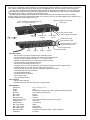
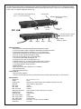
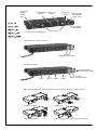
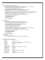
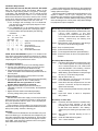
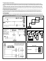
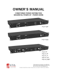
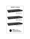
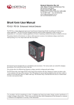
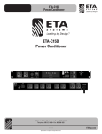
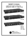
OWNER’S MANUAL
©
SYSTEMS
A Creative Light & Sound Company
1532 Enterprise Parkway • Twinsburg, Ohio 44087
330-425-3388 • 800-321-6699 • Fax: 330-425-9700
http://www.etasys.com E-mail [email protected]
ETA’s line of Conditioned Power Distribution units are designed to reduce damage to sensitive electronic equipment
from sudden voltage spikes, damaging power surges, and EMI/RFI noise, which is inherent in utility power lines.
The PD11SP is a sequential four step/stage power up/down conditioned power distribution unit. It is designed to
protect electronic equipment that requires a time-delayed start-up, particularly when high in-rush current can potentially damage audio, video, or computer equipment at power up.
PD11SP units are shipped with the ability to be linked or daisy chained. All linked units function as slaves;
however, slaves can be set to specific time delays. Any number of units can be linked together with a distance of up
to 1000 feet between each location (see Fig. 4).
Breaker protected and unswitched
15 amp outlet
1 thru 4 steps/stages in sequential power up/
down 1, 5, 10, 30 second pre-sets
20 amp total unit breaker
Sequential
On / Off
Protection "On"
Indicators
Power switch
On / Off
15 amp front panel outlet breaker
Input RCA phono jack
Output RCA phono jack
3 pin terminal block for remote
sequential operation of unit
Output screw terminal
Stage 1
Stage 2
Stage 3
Stage 4
Input screw terminal
PD11SP Features:
• Microprocessor monitored sequential power distribution system
• Four power up/down steps or stages of distributed and conditioned power
• Four pre-set power up/down intervals of 1, 5, 10 or 30 seconds
• Optional manual settings for up to 240 seconds between intervals
• One dual 20 amp U-grounded outlet per stage
• Full 20 amps, 2400 watts capacity per unit
• 12-gauge, 3-prong, 10-foot, 20-amp power cord. Requires 20 amp circuit and receptacle outlet
• Protected "always on" 15 amp AC power outlet on the front panel
• Total unit 20 amp and 15 amp outlet circuit breakers located on front panel
• Three-stage spike and surge protection
• Two-stage EMI/RFI filtration
• Ground and AC line fault check
• One rack space high
• One year limited warranty
Other Features:
• Remote control operation
• Standard rear panel RCA connectors and 2 screw terminals
Specifications:
Dimensions
Weight
Quality
Electrical
Max. amps
Max. watts
Max. front outlet
Spike/surge protection
Clamping level
Response time
Max. surge voltage
Max. surge current
Max. spike energy
Noise attenuation
Certification
19" L x 10" D x 1 3/4" H
10 lbs.
Black powder coated chassis, black anodized aluminum front panel
120V, 50/60 Hz, single phase
20/unit
2400/unit
15 amps
Line to neutral, neutral to ground, line to ground
200V peak
1 nanosecond
6000V
26,000 amps
630 joules total
Transverse greater than 20 dB, 1.5 kHz to 200 MHz
ETL listed
The PD11SS is a sequential four step/stage power up/down conditioned power distribution unit. It is designed to protect
electronic equipment that requires a time-delayed start-up, particularly when high in-rush current can potentially damage
audio, video, or computer equipment at power up.
1 thru 4 steps/stages in sequential power up/
down 1, 5, 10, 30 second pre-sets
15 amp breaker
Breaker protected and unswitched
15 amp outlet
Sequential
On / Off
Power switch
On / Off
Protection "On"
Indicator
3 pin terminal block for remote
sequential operation of unit
Protected
"Always On” Outlets
Stage 1
Stage 2
Stage 3
Stage 4
PD11SS Features:
• Microprocessor monitored sequential power distribution system
• Four power up/down steps or stages of distributed and conditioned power
• Four pre-set power up/down intervals of 1, 5, 10 or 30 seconds
• Optional manual settings for up to 240 seconds between intervals
• One dual 15 amp U-grounded outlet per stage
• One dual 15 amp "always on" U-grounded outlet
• Full 15 amps, 1800 watts capacity per unit
• 12-gauge, 3-prong, 6-foot, 15-amp power cord
• Protected "always on" 15 amp AC power outlet on the front panel
• Total unit 15 amp outlet circuit breakers located on front panel
• Three-stage spike and surge protection
• EMI/RFI filtration
• Watch dog circuitry with "Go/No Go" L.E.D. display
• One rack space high
• One year limited warranty
Other Features:
• Remote control operation
Access to remote feature is internal to three PC board mounted screw terminals for 3-wire hook-up.
Specifications:
Dimensions
Weight
Quality Finish
Electrical
Max. amps
Max. watts
Max. front outlet
Spike/surge protection
Clamping level
Response time
Max. surge voltage
Max. surge current
Max. spike energy
Noise attenuation
Certification
19" L x 10" D x 1 3/4" H
10 lbs.
Black powder coated chassis, black anodized aluminum front panel
120V, 50/60 Hz, single phase
15/unit
1800/unit
15 amps
Line to neutral, neutral to ground, line to ground
200V peak
1 nanosecond
6000V
12,000 amps
450 joules total
Transverse > 35 dB, 1.5 kHz to 200 MHz
ETL listed
3
Pull out lights
ON/OFF
HI/LOW
switch
Digital Voltmeter
Readout
Protection "On"
Indicator
Power switch
On / Off
Breaker protected
and unswitched
15 amp outlet
20 amp Breaker
15 amp Breaker
Pull out lights
Front View PD11LVP Model Shown
Back View PD11P, 11VP, 11LP, 11LVP
Protected
"Always On” 20 amp Outlets
Back View PD11LVSP
3 pin terminal block for
remote sequential operation
Stage 1
Stage 2
Stage 3
Stage 4
Protected
"Always On” 20 amp Outlets
Easy 4-step bulb replacement. Use 120 volt 4 watt bulb (Christmas tree bulb). PD11LP, 11LVP, 11LVSP
1. Twist cap clockwise
3. Replace bulb
2. Release bulb & socket
4. Replace socket, snap on cap, turn cap counter-clockwise
PD11P, PD11VP, PD11LP, PD11LVP Features:
• Light Switch (PD11LP/LVP/LVSP) activates rack illumination; choice of HI or LOW intensity
• Light Tubes (PD11LP/LVP/LVSP) illuminates up to 25 rack spaces
• 4 dual 20 amp U-grounded switched outlets per unit
• 1 dual 15 amp U-grounded "always on" and protected outlet
• Digital Voltmeter Readout (PD11VP/LVP/LVSP) displays incoming line voltage
• Resettable 20 amp thermal circuit breaker; 15 amp for front panel outlet
• Lighted Outlet Power Switch activates protection and filtration to all switch outlets and front panel outlet
• 12-gauge, 3-prong, 10-foot, 20-amp power cord. Requires 20 amp circuit and receptacle outlet
• Protected "always on" 15 amp AC power outlet on the front panel
• Total unit 20 amp and 15 amp outlet circuit breakers located on front panel
• Three-stage spike and surge protection
• Two-stage EMI/RFI filtration
• Ground and AC line fault check
• One rack space high
• One year limited warranty
PD11LVSP Features:
• Microprocessor monitored sequential power distribution system
• Four power up/down steps or stages of distributed and conditioned power
• Four pre-set power up/down intervals of 1, 5, 10 or 30 seconds
• Optional manual settings for up to 240 seconds between intervals
• One dual 120 amp U-grounded outlet per stage
• One dual 20 amp "always on" U-grounded outlet
• Full 20 amps, 2400 watts capacity per unit
• 12-gauge, 3-prong, 10-foot, 20-amp power cord. Requires 20 amp circuit and receptacle outlet
• Protected "always on" 15 amp AC power outlet on the front panel
• Total unit 20 amp and 15 amp outlet circuit breakers located on front panel
• Three-stage spike and surge protection
• Two-stage EMI/RFI filtration
• Ground and AC line fault check
• One rack space high
• One year limited warranty
Other Features:
• Remote control operation
• The remote feature is accessed externally through a 3-wire remote block
PD11LVSP/LVP/LP/VP/P Specifications:
Dimensions
Weight
Quality Finish
Electrical
Max. amps
Max. watts
Max. front outlet
Spike/surge protection
Clamping level
Response time
Max. surge voltage
Max. surge current
Max. spike energy
Noise attenuation
Certification
19" L x 10" D x 1 3/4" H
10 lbs.
Black powder coat chassis, black anodized aluminum front panel
120V, 50/60 Hz, single phase
20/unit
2400/unit
15 amps
Line to neutral, neutral to ground, line to ground
200V peak
1 nanosecond
6000V
23,000 amps (PD11LVSP/LVP/VP/LP/P)
630 joules total
Transverse > 20 dB, 1.5 kHz to 200 MHz
ETL listed
Installation Requirements
PD11P, PD11VP, PD11LP, PD11SP, PD11LVP, PD11LVSP
Plug unit into power source and observe status of four
"Protection" light emitting diodes. The (green) “1st Stage”,
“2nd Stage”, and “GROUND OK” L.E.D.’s should normally
be illuminated and the (red) “FAULT” L.E.D. should be off.
When these indications are present, test the power “On/Off”
switch which will illuminate to indicate that power is being
supplied to the switched outlets on the rear of the unit.
A. The “1st Stage” and “2nd Stage” L.E.D.’s indicate that
both the input (1st) and output (2nd) stages of circuit
protection are active.
B. The “GROUND OK” L.E.D. indicates that the chassis
is connected to the ground wire of the supply outlet.
C. Fault conditions are represented by the following
indications:
NOTE: (X) = “ON” ( ) = “OFF”
1st
2nd Ground Fault
Stage Stage OK
(X)
( )
(X)
( )
(X)
( )
( )
( )
( )
( )
(X)
(X)
(X)
(X)
(X)
(X)
( )
( )
( )
(X)
Supply circuit outlet wiring OK
Open hot
Open Neutral or
Hot & Ground Reversed
Open Ground
Hot & Neutral Reversed
NOTE: On the PD11SS Model a green L.E.D. located on the
front panel is illuminated (indicating “Protection On” status)
when unit is plugged into a power source ensuring input and
output stages of circuit protection are active.
Operating Instructions
1. Install in a standard 19" rack or free-standing position.
2. Connect Power Distribution power cord into a 20 amp,
120 volt wall outlet (15 amp for Model PD11SS).
3. Plug sensitive electrical equipment into conditioned
outlets. All models have an additional protected outlet on
the front panel.
4. Move power outlet switch to "ON" position to provide
power to electrical equipment.
5. For illumination, pull out light tubes (PD11LP/LVP/LVSP)
and move light switch to "HI" or "LOW" position.
IMPORTANT! Be sure light switch is in "OFF"
position when light tubes are recessed.
6. Digital voltmeter readout (PD11VP/LVP/LVSP) is
calibrated to nominal 117V at the factory. No adjustment
necessary.
7. Digital voltmeter readout automatically displays
incoming voltage when power cord is connected.
Power Problems
Standard AC outlets often supply raw and unprocessed
power that not only can diminish the clarity of audio signals
and cause premature failure of parts, it can completely destroy your valuable equipment.
Power problems such as spikes, line surges and noise
interference transmit through all standard electrical lines and
affect power quality: therefore, affecting you.
Solutions
Conditioned Power Distribution can eliminate such problems from affecting you. As it filters the line voltage from your
AC outlets, eliminating noise and interference, such as radio
frequency interference (RFI) and electromagnetic interference (EMI), it will reduce the residual noise in the system,
which will enhance audio clarity.
6
Audio Conditioned Power Distribution is also designed to
protect electronic equipment from potentially damaging highvoltage spikes and surges.
Sequencing Audio Conditioned Power Distribution is designed to initiate a turn-on cycle, energizing one circuit
immediately with remaining circuits energizing in a delayed
fashion. This allows circuits to stabilize when powering up and
down eliminating that on-rush of power and potential damage
to equipment at output receptacle.
Quick Step Pre-Set Selection for Sequential Models
Step 1: Hold down OFF/ON switch simultaneously until
L.E.D.’s flash together. If unit was
previously set in a manual mode, all channel
L.E.D.’s will be ON rather than ON/OFF L.E.D.
flashing. Assume they are flashing and
proceed to next step.
Step 2: While flashing, press ON button to step through
the four (1,5,10,30 seconds) pre-sets.
Step 3: Stop on desired pre-set.
Step 4: Press OFF/ON switch simultaneously.
Step 5: To test sequential selection press ON button.
Step 6: Press OFF button to return to sequential OFF
Position.
Quick Step Manual Selection
Step 1: Hold down OFF/ON switch simultaneously until
L.E.D.’s flash together. If unit was previously
set in a manual mode, all L.E.D.’s will be ON
rather than ON/OFF L.E.D. flashing. Assume
they are flashing and proceed to next step.
Step 2: While flashing, press ON button to step through
the four (1,5,10,30 seconds) pre-sets.
Step 3: Stop at channel four (4).
Step 4: Press ON button one more time. All channel
L.E.D.’s should now be lighted.
Step 5: Press ON to start time sequence from 5 to 240
seconds. Press OFF to stop time sequence.
(Exits at 240 seconds.)
Step 6: To test manual sequential selection press ON
button.
Step 7: Press OFF button to return to sequential
OFF position.
Quick Step To Clear Unit
Step 1: Hold down OFF/ON switches simultaneously
until L.E.D.’s flash together. If unit was
previously set in a manual mode, all L.E.D.’s will
be ON rather than ON/OFF L.E.D. flashing.
Assume they are flashing and proceed to next
step.
Step 2: Step through channels stopping at one or
1 second.
Step 3: Press OFF/ON switches together.
Step 4: Test — same as above
Three-Wire Remote Control Interface
A three-wire remote control interface is added to the main PC board for the PD11SS, PD11SP AND PD11LVSP units. This remote control
interface is accessible through an external terminal block on the back of the unit (see Figure 6). This interface requires an external user provided
switch, L.E.D., and a three-wire cable to implement. The interface has been tested reliably over 1000 feet with 22-gauge speaker wire (see Figures
1 and 5).
Connect the short minus (-) lead of the L.E.D. and one side of the switch to the COMMON terminal, the long plus (+) lead of the L.E.D. to the
L.E.D. terminal, and finally the other side of the switch to the ON/OFF terminal. When you close the switch, the L.E.D. will begin flashing until all
channels have sequenced ON, and then the L.E.D. will remain ON. When you open the switch the L.E.D. will begin flashing until all channels have
sequenced OFF and then the L.E.D. will remain OFF.
Remote Relay Function Operation (optional)
Using a set of relay contacts that are normally open instead of a switch you can control the PD11SS, PD11SP AND PD11LVSP units with a
relay. When you apply power to the relay the channels will sequence ON, and when you disconnect power from the relay the channels will
sequence OFF. This allows you to interface a PD11SS, PD11SP AND PD11LVSP unit with other equipment that has dry (normally open) relay
contacts (see Figure 2).
Larger Installations
In a larger installation, you can control different equipment racks from a remote location by running three-wire cable from each rack back to the
remote location. Then attach an L.E.D. and switch as before, these would be mounted in the user's control panel, and you now have remote control
of each rack in a single location (see Figure 3).
Fig. 4
Fig. 1
Standard use of 3-wire interface with L.E.D.
over 22 gauge wire.
Fig. 5
Fig. 2
Use of relay to control
3-wire interface
and L.E.D.
Can be used to extend
range of control beyond
1000 ft. or to control
3-wire interface from an
external voltage source.
Fig. 6
Fig. 3
Expansion connector for use with external
relays to provide dry contacts for channels
3 and 4. Relay coils should be 12V DC
and not draw more than 100 milliamps.
TOP OF CASE
L.E.D
REAR PANEL
COMMON
SWITCH
ETA Conditioned Power Distribution...
The Benchmark By Which Professionals Compare.
For over 20 years ETA has developed, manufactured
and sold high amperage theatrical lighting systems from
which evolved an extensive line of rack mounted conditioned power distribution products designed to protect
today’s sensitive electronic digital equipment.
The “PD” Conditioned Power Distribution Series easily
deals with normal AC line power fluctuations, as well as
the more drastic abnormalities of the spike and surge
variety. Also, filtering of airborne interferences caused by
electromagnetic and radio frequency
transmissions is routinely accomplished.
Quality
More sophisticated ETA models utilize
And
microprocessor technology to regulate
Service
AC power and sequence power turn-on—
reducing high in-rushes of power.
ETA’s sophisticated electronic protection technology is the
favorite of professional who demand flawless operation of
digital mixers, processors, amplifiers and PCs—whether
in the studio, in the boardroom, on tour, or in a home
entertainment environment.
Thank you for choosing ETA Systems Power Distribution
Drawing upon our 20 years of solving high-amperage
lighting needs and listening to customers’ concerns, we
have developed a most extensive line of Audio Conditioned Power Distribution. As the problems inherent with
AC power increase, you will find ETA providing solutions.
Power Conditioning Firsts
from ETA
• “Always-On” Protected Outlets
• 10 Rear Panel Outlets
• Front Panel Convenience Outlets
• Digital Voltmeter Display Readouts
• Microprocessor Managed Voltage Regulators
• Programmable and Linkable Sequential Turn-on Models
• Models Adaptable for Multiple AC Adapters
• High Amp Conditioned Models
• Easy Bulb Change Feature
Standard on Every ETA Power Conditioning Model
• Spike and Surge Protection and EMI/RFI Filtration on
All Three Legs of the Incoming AC Power—A Must
to Ensure Protection of Electronic Components and
Equipment.
Typical Uses
All Professional Permanent Installations, Recording
Studios, Theatres, Schools, Clubs, Churches, any entertainment venue, business board rooms, and audio/
visual multi-use presentation rooms.
Portable Applications : On-The-Road Concert Tours,
Bands, and D.J. services.
Other Important Applications: A/V racks, computer
networks, and home entertainment centers.
Call 1-800-321-6699 for a Full Line Brochure
©
TM
SYSTEMS
A Creative Light & Sound Company
1532 Enterprise Parkway • Twinsburg, Ohio 44087
330-425-3388 • 800-321-6699 • Fax: 330-425-9700
http://www.etasys.com E-mail [email protected]
All designs and specifications are subject to change without notice.
Copyright © 1998 ETA Systems.
8/99 6MAN-021