1
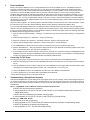
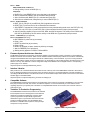
P&E Microcomputer Systems, Inc.
www.pemicro.com
Technical Summary for
USB Multilink Universal, Rev. B (PART# USB-ML-UNIVERSAL) and
USB Multilink Universal FX, Rev. A (PART# USB-ML-UNIVERSAL-FX)
Support for Freescale Kinetis® · Qorivva® MPC5xxx · ColdFire® V1/ColdFire+ V1 · ColdFire V2-4
PX Series · HCS08 · RS08 · HC(S)12(X) · S12Z · DSC · HC16/683xx (FX only)
Document# PE4576, Version 1.01
1. Introduction
2. Usage
3. Driver Installation
4. Connecting To The Target
5. Troubleshooting - Startup Reset Sequence
6. Firmware Updates/Architecture Selection
7. Interface Libraries
8. Compatible Software
9. Transition To Production Programming
1
Introduction
USB Multilink Universal & USB Multilink Universal FX
The USB Multilink Universal and Universal FX are allin one debug interfaces which accelerate the debug and flash programming process, saving valuable development time. Both
Multilinks provide access to debug modes on a wide range of Freescale microcontroller families by communicating between the
target device and a laptop/PC via the target’s standard debug header and the laptop/PC’s USB port.
FX Note: In addition, the USB Multilink Universal FX offers up to 10X faster download speeds and can provide target
power.
Each of the supported families of Freescale microcontrollers are represented by headers located inside the unit. The headers
for Ports A-D & Port H (FX only) are dual-row with a .100” pitch, and the headers for Ports F-G are dual-row with a .050” pitch.
The pin-outs for these connections and the families that they support are shown below. Port E, the 16-pin JTAG/COP connector,
is not currently supported.
Universal/Universal FX Pin-Outs, Ports A-D
©2012 P&E Microcomputer Systems, Inc. Kinetis, Qorivva, and ColdFire are registered trademarks of Freescale Semiconductor, Inc.
The Power Architecture wordmark and related marks are trademarks and service marks licensed by Power.org.
Universal/Universal FX Pin-Outs, Ports F-H
The user can take advantage of debug modes to halt normal processor execution and use a computer to control the processor.
The user can then directly control the target's execution, read/write registers and memory values, debug code on the processor,
and program internal or external FLASH memory devices.
FX Note: The USB Multilink Universal FX is capable of providing power (5V or 3.3V) directly to the target processor via
the TVCC pin. This removes the need for an external power supply for systems requiring 200mA of current or less.
2
Usage
The USB Multilink Universal and Universal FX can communicate with Kinetis (including L-Series devices), Qorivva MPC5xxx,
ColdFire V1/V2/V3/V4, Power Architecture PX Series, RS08, HCS08, HC(S)12(X), S12Z, DSC, and HC16/683xx (FX only)
microprocessors by connecting a ribbon cable between the target's debug header and one of the multiple ports on the Multilink.
Do not attempt to use multiple ports at once, as this may damage both the target processors as well as the Multilink.
The USB Multilink Universal and Universal FX interfaces will work with targets whose processor power supply is in the range of
1.8V to 5V.
On the Universal FX, if the user wishes to provide power to the target, the JP10 Jumper (FX only) is used to enable this option
and select the voltage. A shunt at position 1-2 enables 5V, while a shunt at position 2-3 enables 3.3V. The USB Multilink
Universal and Universal FX have a female type B USB connector. Use a Type A to Type B male-to-male USB cable to connect
the interface to the PC.
Universal/Universal FX Header Layout (Pin 1 Highlighted)
There are two LEDs on the Multilink interface. The blue LED indicates that the interface is powered and running. The yellow
LED indicates that target power has been detected.
Note:
If connecting to a ColdFire V2-4 processor which requires synchronous communication, such as the
MCF5272 and MCF5206(E), a CABLE-CF-ADAPTER (sold separately) is required.
Note:
To avoid improper connections, the red stripe of the ribbon cable should always be oriented towards Pin 1,
both on the Multilink port and the target processor header.
The USB Multilink Universal and Universal FX are USB devices. If a USB Hub is used, it must be a self-powered hub (i.e. with
its own power supply). By default, the USB protocol used is USB 2.0.
USB Multilink Universal & USB Multilink Universal FX - Technical Summary
3
Driver Installation
Before connecting the Multilink to the PC, the appropriate drivers need to be installed on the PC. The Multilink drivers are
supported on Windows XP, 2000, 2003, Vista, and 7. These drivers are automatically installed when installing Freescale’s
CodeWarrior or any of P&E’s recent software development packages. If you have installed a recent version of these then the
instructions for manual installation that follow are not necessary. However, Windows 7 users who are installing software
distributed before December 28, 2009 will need to obtain the latest version of the drivers and install them manually. A copy of
the driver installation program may be downloaded from the “Downloads” section of P&E’s “Support Center” located at http://
www.pemicro.com. If you are using third-party software, make sure you have a version which supports your specific interface
(Universal/FX). Once you have obtained the latest version of the driver installation program, please use the instructions below to
manually install the drivers.
When the cable is plugged in, the operating system should indicate that it has found a driver for the attached interface. Follow
the instructions in the “Found New Hardware Wizard” dialog for having Windows automatically install the driver.
If you connected the Multilink interface prior to installing the drivers, Windows will not have been able to find the appropriate
driver and may have disabled the device. If you unplug the device and then plug it in again, Windows will automatically disable
it even if you have installed the drivers. To force Windows to attempt to load the driver again, perform the following steps while
the Multilink interface is plugged into the computer:
1. Open the Control Panel: Start Button [ ->Settings ] ->Control Panel. (You will not need to select “Settings” on Vista and Windows 7).
2. Double Click the “System” Icon. (Windows 7: “System and Security”)
3. Select the “Hardware” Tab. (Windows 7: “Hardware and Sound”, Windows Vista: skip this step)
4. Click the “Device Manager” Button. (Windows 7: “Devices and Printers -> Device Manager”)
5. The “USB Multilink 2.0” device will be shown with an exclamation point next to it. Double-click this device.
6. Click the “Reinstall Driver…” button and follow the dialog instructions to have Windows automatically install the driver. (Windows 7: First click the “Driver” tab, then select “Update Driver...”)
7. If the hardware still has a yellow exclamation mark next to it, right click on it and select uninstall. The USB Multilink should
disappear from the list. Unplug the USB Multilink and then plug it into the PC again. A new Hardware Found dialog will pop
up; follow the dialog instructions and have Windows automatically install the driver.
4
Connecting To The Target
The following is the proper connection sequence to connect the PC to the target system via the Multilink interface:
1. Make sure the target power is OFF and the USB Multilink Universal or Universal FX is not connected to either the target or
the PC
2. Open the Multilink and connect a ribbon cable from the correct Multilink port to the target. Make sure that the ribbon cable
is plugged into the target with the proper orientation. PIN 1 is indicated by a 1 next to the port.
3. Connect the Multilink to the PC via a USB cable. The Blue LED on the Multilink should illuminate.
4. Turn the target power on. The Yellow LED on the Multilink should illuminate.
Before disconnecting the setup, turn the target power off.
5
Troubleshooting - Startup Reset Sequence
Note that if the Multilink does not enter debug mode, the program issues the error message “Cannot enter background mode.” If
you receive this message you should check your hardware with a scope, logic analyzer or logic probe. First check for power on,
then check to make sure the processor oscillator is running. Finally, look for the startup sequence for your microprocessor that
is listed below.
Port A – JTAG/ONCE – Qorivva MPC5xxx, Power Architecture PX Series, DSC
a. RESET (Pin-9) is driven low (to processor).
b. Activity appears on TCK (Pin-5), TDI (Pin-1) and TDO (Pin-3). (PC software instructs the processor to
enable debug mode).
c. RESET (Pin-9) is released by the interface and will go high.
d. Activity appears on TCK (Pin-5), TDI (Pin-1) and TDO (Pin-3). (Debug activity).
Ports B, F, G – ARM JTAG - Kinetis
a. RESET is driven low (to processor).
b. Activity appears on TCK, TDI and TDO (PC software instructs the processor to enable debug mode).
c. RESET is released by the interface and will go high.
d. Activity appears on TCK , TDI and TDO (Debug activity).
USB Multilink Universal & USB Multilink Universal FX - Technical Summary
Port C – BDM
RS08, HCS08, S12Z, ColdFire V1
a. Debug activity is seen on BKGD (Pin-1).
HC(S)12(X)
a. BKGD (Pin-1) and RESET (Pin-4) are pulled low by the interface.
b. After 5 milliseconds, RESET (Pin-4) is released and goes high.
c. After 10 milliseconds, BKGD (Pin-1) is released and goes high.
d. After 20 more milliseconds, debug activity is seen on BKGD (Pin-1).
Port D – Coldfire V2/V3/V4
a. BKPT (Pin-2), DSI (Pin-8), and DSCLK (Pin-4) signals are driven low.
b. RESET (Pin-7) is driven low for 20+ milliseconds and released.
c. After RESET is released and if the processor has correctly entered background mode, the PST0 (Pin-15),
PST1 (Pin-14), PST2 (Pin-13) and PST3 (Pin-12) lines should all be driven high by the processor.
d. Activity (changing signals) is seen on the DSI, DSO, and DSCLK signals. The activity on the DSCLK and
DSI lines is generated by the PC and the activity on the DSO line is generated by the processor.
Port E – JTAG/COP (Not yet supported)
Port H - HC16/683XX (FX Only)
a. BKPT/DSCLK is pulled low (to processor).
b. Delay ~1ms.
c. RESET is pulled low (to processor).
d. Delay ~20ms.
e. RESET is released (tri state, should be pulled up on target).
f. Wait for FREEZE (out of processor).
g. Shifting activity appears on DSCLK, DSI and DSO.
6
Firmware Updates/Architecture Selection
The Multilink Universal and Universal FX use firmware updates to change between modes of operation to support different
families of Freescale microcontrollers. Older versions of P&E's software and third-party software are not able to automatically
configure these Multilinks when the target is switched to a different family of microcontrollers. If you are not using the latest
version of P&E software, please contact us to determine if you are eligible for a discounted upgrade to the latest version of your
software. You may also download a manual configuration utility for the Multilink from the Support Center or corresponding
product page on our website:
http://www.pemicro.com/support/downloads_find.cfm
7
Interface Libraries
P&E produces a set of interface libraries which allow the user to directly control the USB Multilink Universal or Universal FX
from any Windows Development environment which can interact with a DLL. The interface libraries come with examples for
controlling the Multilink interface from Microsoft Visual C as well as Borland Delphi. More details can be found on the Interface
Libraries page on the P&E website:
http://www.pemicro.com/products/product_processor.cfm?category=9
8
Compatible Software
The USB Multilink Universal and Universal FX are supported by recent versions of Freescale’s CodeWarrior (10.x) as well as
third-party toolchains from IAR, Keil, Cosmic, and Ment.or Graphics. It is recommended that you check with the vendor
regarding support for your specific part. Information on compatible P&E software can be found in the “Products” section of
www.pemicro.com.
9
Transition To Production Programming
The USB Multilink Universal and Universal FX are intended
for development and are not designed to accomodate the
demands of production programming. However, P&E’s
Cyclone programmers are specifically engineered to
withstand the rigors of a production environment and will
provide a seamless transition from the Multilink. More
information is available online at pemicro.com/cyclonepro
and pemicro.com/cyclonemax.
Cyclone PRO & Cyclone MAX
USB Multilink Universal & USB Multilink Universal FX - Technical Summary