1
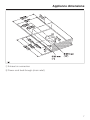
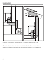
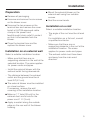
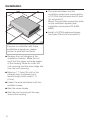
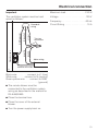
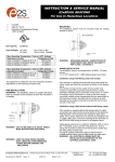
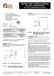
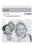
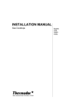
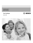
Operating and Installation
Instructions
External Blower
DAG 1000
To prevent accidents
and appliance damage,
read these instructions
before
installation or use.
en - US, CA
M.-Nr. 07 915 550
2
Contents
IMPORTANT SAFETY INSTRUCTIONS. . . . . . . . . . . . . . . . . . . . . . . . . . . . . . . . . 4
Functional description . . . . . . . . . . . . . . . . . . . . . . . . . . . . . . . . . . . . . . . . . . . . . 6
Appliance dimensions . . . . . . . . . . . . . . . . . . . . . . . . . . . . . . . . . . . . . . . . . . . . . . 7
Installation . . . . . . . . . . . . . . . . . . . . . . . . . . . . . . . . . . . . . . . . . . . . . . . . . . . . . . . 8
Preparation . . . . . . . . . . . . . . . . . . . . . . . . . . . . . . . . . . . . . . . . . . . . . . . . . . . . . . . 9
Installation on an external wall . . . . . . . . . . . . . . . . . . . . . . . . . . . . . . . . . . . . . . . . . 9
Installation on a roof. . . . . . . . . . . . . . . . . . . . . . . . . . . . . . . . . . . . . . . . . . . . . . . . . 9
Air extraction . . . . . . . . . . . . . . . . . . . . . . . . . . . . . . . . . . . . . . . . . . . . . . . . . . . . 11
Electrical connection . . . . . . . . . . . . . . . . . . . . . . . . . . . . . . . . . . . . . . . . . . . . . . 12
After Sales Service . . . . . . . . . . . . . . . . . . . . . . . . . . . . . . . . . . . . . . . . . . . . . . . 14
Caring for the environment . . . . . . . . . . . . . . . . . . . . . . . . . . . . . . . . . . . . . . . . . 15
3
IMPORTANT SAFETY INSTRUCTIONS
READ AND SAVE THESE
INSTRUCTIONS
Keep these operating instructions in
a safe place and pass them on to any
future user.
Read these Instructions carefully
before installing or using the
Ventilation System.
~ This appliance is intended for
residential use only. Use the appliance
only for its intended purpose.
~ This appliance complies with current
safety requirements. Improper use of
the appliance can lead to personal
injury and material damage.
,CAUTION
For General Ventilating Use
Only. Do Not Use To Exhaust
Hazardous Or Explosive
Materials And Vapors.
~ This appliance is designed to vent
cooking smoke and odors only.
~ This appliance is not intended for
outdoor use.
This appliance must not be used in a
non-stationary location (e.g. on a ship).
4
,WARNING
TO REDUCE THE RISK OF
FIRE, ELECTRIC SHOCK, OR
INJURY TO PERSONS,
OBSERVE THE FOLLOWING:
~ a) Use this appliance only in the
manner intended by the manufacturer.
If you have questions, contact Miele.
~ b) Before servicing or cleaning the
appliance, switch power off at the
service panel and lock the service
disconnecting means to prevent power
from being switched on accidentally. If
the service disconnecting means
cannot be locked, securely fasten a
prominent warning device, such as a
tag, to the service panel.
~ c) Be certain your appliance is
properly installed and grounded by a
qualified technician.
To guarantee the electrical safety of this
appliance, continuity must exist
between the appliance and an effective
grounding system. It is imperative that
this basic safety requirement be met. If
there is any doubt, have the electrical
system of the house checked by a
qualified electrician.
IMPORTANT SAFETY INSTRUCTIONS
~ d) Before connecting the appliance
to the power supply make sure that the
voltage and frequency listed on the
data plate correspond with the
household electrical supply.
This data must correspond to prevent
appliance damage. If in doubt consult a
qualified electrician.
Installation
~ e) Installation work and repairs
should only be performed by a qualified
technician in accordance with all
applicable codes and standards.
Repairs and other work by unqualified
persons could be dangerous.
~ a) Installation work and electrical
~ f) Only open the housing as
described in the enclosed "Installation
diagram" and in the "Cleaning and care"
section of this manual. Under no
circumstances should any other parts
of the housing be opened. Tampering
with electrical connections or
components and mechanical parts is
highly dangerous to the user and can
cause operation faults.
combustion and exhausting of gases
through the flue (chimney) of fuel
burning equipment to prevent back
drafting. Follow the heating equipment
manufacturer’s guideline and safety
standards such as those published by
the National Fire Protection Association
(NFPA) and the American Society for
Heating, Refrigeration and Air
Conditioning Engineers (ASHRAE), and
the local code authorities.
~ g) Before discarding an old
appliance, disconnect it from the power
supply and remove the power cord to
prevent hazards.
Use
~ Do not use a steam cleaner to clean
the appliance. Steam could penetrate
electrical components and cause a
short circuit.
,WARNING
TO REDUCE THE RISK OF
FIRE, ELECTRIC SHOCK, OR
INJURY TO PERSONS,
OBSERVE THE FOLLOWING:
wiring must be done by qualified
person(s) in accordance with all
applicable codes and standards,
including fire-rated construction.
~ b) Sufficient air is needed for
~ c) When cutting or drilling into the
wall or ceiling, do not damage electrical
wiring and other hidden utilities.
~ d) Ducted hoods must always be
vented to the outdoors.
~ e) Any fittings, sealant, or materials
used to install the ductwork must be
made of approved non-flammable
materials.
,WARNING
TO REDUCE THE RISK OF
FIRE USE ONLY METAL
DUCTWORK.
5
Functional description
The external blower should only be
used in combination with Miele
ventilation systems DA 6480 or
DA 6490.
It must be mounted outside the kitchen
on an external wall or on the roof.
The external blower is connected to the
ventilation system by an exhaust duct
and power cord. It is operated by
means of the ventilation system control
panel.
The external blower is equipped with a
non-return flap so that no exchange of
outside air and room air can occur
when the ventilation system is shut off.
It is closed when the ventilation system
is off.
When the blower is turned on, the
non-return flap opens so that the
exhaust air can be transported outside.
6
Appliance dimensions
a Exhaust air connection
b Power cord feed-through (strain relief)
7
dai2749
Installation
Example: Installation on an external wall
Example: Installation on a roof
The exhaust connection can be connected to either the front or back of the
downdraft. For more information see the installation diagram for the downdraft.
8
Installation
^ Remove all packaging.
^ Mount the external blower on the
external wall using four suitable
screws.
^ Unscrew and remove the six screws
on the blower cover.
^ Seal the screw heads.
Preparation
^ Unscrew the two screws on the
terminal box and remove the cover.
Install a UL/CSA-approved cable
clamp in the power cord
feed-through (strain relief). Locate it
so that it is accessible from the
blower.
Installation on a roof
^ Close the terminal box and the
replace the blower cover.
– Make sure that there are no
supporting elements in the roof at the
installation location. The same
applies for power cords and pipes.
Installation on an external wall
Select a suitable installation location.
– Make sure that there are no
supporting elements in the wall at the
selected location. The same applies
for power cords and pipes.
Select a suitable installation location.
– The angle of the roof must be at least
10°.
For installation on a flat roof, consult
a qualified contractor.
– The exhaust outlet must face down
and away from the main wind
direction.
– Install the external blower with the
exhaust outlet facing downwards.
– The distance between the exhaust
outlet and the ground must be at
least 24" (61 cm).
^ The external blower must be installed
on a level surface.
If necessary, remove the wall
covering at the installation location.
^ Make an 11" hole (28 cm) for the
exhaust duct and a hole for the
power cord 1 ¼" (3 cm).
^ Apply a sealant along the outside
edge on the rear wall of the blower
housing.
9
Installation
^ The external blower and the
ventilation system are connected by
a 10" (254 mm) exhaust duct C (see
"Air extraction").
Mount the provided connection plate
on the ventilation system (see
installation instructions DA 6480,
6490).
^ Install a UL/CSA-approved power
cord (see "Electrical connection").
If unsure or unfamiliar with these
installation procedures, please
contact a qualified contractor.
^ Remove the roof shingles at the
installation location. Make the cut
such that the upper and side edges
of the housing frame sit under the
roof covering and the lower edge sits
over the roof covering.
^ Make an 11" hole (28 cm) for the
exhaust duct and power cord
feed-through (strain relief) 1 ¼"
(3 cm).
^ Fasten the external blower with four
suitable screws.
^ Seal the screw heads.
^ Seal the roof covering all the way
around the housing.
10
Air extraction
,WARNING
Danger of toxic fumes.
Gas cooking appliances release
carbon monoxide that can be
harmful or fatal if inhaled.
To reduce the risk of fire and to
properly exhaust air, the exhaust
gases extracted by the hood
should be vented outside of the
building only.
Do not vent exhaust air into
spaces within walls or ceilings or
in attics, crawl spaces or garages.
To reduce the risk of fire, only use
metal ductwork.
Please read and follow the
"IMPORTANT SAFETY
INSTRUCTIONS" to reduce the risk of
personal injury. Follow all local building
codes when installing the hood.
Exhaust ducting and connections
– The ducting should be as short and
straight as possible, and the number
of sharp bends should be minimized.
– For most efficient air extraction, the
diameter of the ductwork should not
be less than 10" (254 mm). Use of flat
ducts also reduces the air extraction
efficiency.
– Noise levels of the hood will increase
if flat ducts or round ducts of less
than 10" (254 mm) in diameter are
used.
– Use smooth or flexible pipes made
from approved non-flammable
materials for exhaust ducting.
– Where the ductwork is horizontal, it
must slope away from the hood at
least 1/8" per foot (1 cm per meter) to
prevent condensation dripping into
the appliance.
Important
If the ductwork runs through rooms,
ceilings, garages, etc. where
temperature variations exist, it may
need to be insulated to reduce
condensation.
11
Electrical connection
,WARNING
TO REDUCE THE RISK OF
FIRE, ELECTRIC SHOCK, OR
INJURY TO PERSONS,
OBSERVE THE FOLLOWING:
All electrical work should be
performed by a qualified electrician
in strict accordance with national
regulations (for USA: ANSI-NFPA 70)
and local safety regulations.
Installation, repairs and other work
by unqualified persons could be
dangerous.
Ensure that power to the appliance
is off while installation or repair work
is performed.
This external blower may only be
operated with Miele DA 6480 or
DA 6490 ventilation systems.
^ Verify that the voltage, load and
circuit rating information found on the
data plate, match the household
electrical supply before installing the
blower.
If there is any question concerning the
electrical connection of this appliance
to your power supply, please consult a
licensed electrician or contact Miele’s
Technical Service Department. See
back cover for contact information.
WARNING:
THIS APPLIANCE MUST BE
GROUNDED
12
Important : To increase security
before the machine is installed, it is
recommended to install a protective
switch (30 mA).
^ Remove the cover from the external
blower.
^ Remove the cover of the terminal
box.
^ Install a suitable UL listed cable
clamp or conduit fitting at the power
cord feed-through (strain relief).
^ Install a power cord to the ventilation
system.
Flexible armored or nonmetallic cable
must be used.
Wire sizes must conform to the
requirements of the National
Electrical Code ANSI/NFPA 70 —
latest edition or Canadian Electrical
Code, C22.1 and C22.2 No.
113-M1984 (or latest edition), and all
local codes and ordinances. 14
gauge wire (minimum) is
recommended.
A U.L./CSA-listed strain relief must be
provided at each end of the power
cord.
^ Pass the power cord through the
strain relief.
Electrical connection
Important
Maximum load . . . . . . . . . . . . . . . 210 W
The ventilation system must be hard
wired as follows:
Voltage . . . . . . . . . . . . . . . . . . . . . 120 V
N (neutral)
L1 (live)
WHITE
BLACK
Ground screws
GND (ground)
Downdraft
wiring
Frequency . . . . . . . . . . . . . . . . . . 60 Hz
Circuit Rating . . . . . . . . . . . . . . . . . 15 A
Twist-on
connectors
Motor wiring
GREEN-YELLOW
dai2748
Black wire: . . . . . . . connect to L1 (live)
White wire: . . . . . connect to N (neutral)
Green-yellow wire: . . . connect to GND
. . . . . . . . . . . . . . . . . . . . . . . . . (ground)
^ The remote blower must be
connected to the ventilation system
wiring as described in the manual for
DA 6480/6490.
^ Close the terminal box.
^ Close the cover of the external
blower.
^ Turn the power supply back on.
13
After Sales Service
Repairs
In the event of a fault which you cannot
easily fix yourself, please contact the
Miele Technical Service Department.
^ When contacting the Technical
Service Department, please have the
model and serial number of your
appliance available.
These can be found on the data plate
located on the housing above the
connection box.
14
Caring for the environment
Disposal of packing material
Disposal of an old appliance
The cardboard box and packing
materials protect the appliance during
shipping. They have been designed to
be biodegradable and recyclable.
Please recycle.
Old appliances may contain materials
that can be recycled. Please contact
your local recycling center about the
possibility of recycling these materials.
,DANGER
Ensure that any plastic wrappings,
bags, etc., are disposed of safely
and kept out of the reach of babies
and young children. Danger of
suffocation!
Before discarding an old appliance,
disconnect it from the electrical
supply and cut off the power cord to
prevent it from becoming a hazard.
15
Alteration rights reserved / 1711
M.-Nr. 07 915 550 / 02
INFORMATION IS SUBJECT TO CHANGE. PLEASE REFER TO OUR WEBSITE TO OBTAIN THE MOST
CURRENT PRODUCT SPECIFICATIONS, TECHNICAL & WARRANTY INFORMATION.