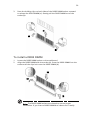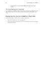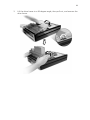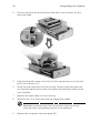
1
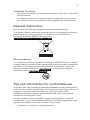
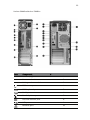
Veriton Series
User's Guide
Copyright © 2006. Acer Incorporated.
All Rights Reserved.
Veriton Series User's Guide
Original Issue: 08 / 2006
Changes may be made periodically to the information in this publication without obligation
to notify any person of such revisions or changes. Such changes will be incorporated in new
editions of this manual or supplementary documents and publications. This company makes
no representations or warranties, either expressed or implied, with respect to the contents
hereof and specifically disclaims the implied warranties of merchantability or fitness for a
particular purpose.
Record the model number, serial number, purchase date, and place of purchase information in
the space provided below. The serial number and model number are recorded on the label
affixed to your computer. All correspondence concerning your unit should include the serial
number, model number, and purchase information.
No part of this publication may be reproduced, stored in a retrieval system, or transmitted, in
any form or by any means, electronically, mechanically, by photocopy, recording, or otherwise,
without the prior written permission of Acer Incorporated.
Veriton Series Desktop Computer
Model number: __________________________________
Serial number: ___________________________________
Purchase date: ___________________________________
Place of purchase: ________________________________
Acer and the Acer logo are registered trademarks of Acer Incorporated. Other companies'
product names or trademarks are used herein for identification purposes only and belong to
their respective companies.
i
Information for your safety and
comfort
Safety instructions
Read these instructions carefully. Keep this document for future reference.
Follow all warnings and instructions marked on the product.
Turning the product off before cleaning
Unplug this product from the wall outlet before cleaning. Do not use liquid
cleaners or aerosol cleaners. Use a damp cloth for cleaning.
Warnings
•
•
•
•
•
Do not use this product near water.
Do not place this product on an unstable cart, stand or table. If the product
falls, it could be seriously damaged.
Slots and openings are provided for ventilation to ensure reliable
operation of the product and to protect it from overheating. These
openings must not be blocked or covered. The openings should never be
blocked by placing the product on a bed, sofa, rug or other similar surface.
This product should never be placed near or over a radiator or heat
register, or in a built-in installation unless proper ventilation is provided.
Never push objects of any kind into this product through cabinet slots as
they may touch dangerous voltage points or short-out parts that could
result in a fire or electric shock. Never spill liquid of any kind onto or into
the product.
To avoid damage of internal components and to prevent battery leakage,
do not place the product on a vibrating surface.
Using electrical power
•
•
•
•
This product should be operated from the type of power indicated on the
marking label. If you are not sure of the type of power available, consult
your dealer or local power company.
Do not allow anything to rest on the power cord. Do not locate this
product where people will walk on the cord.
If an extension cord is used with this product, make sure that the total
ampere rating of the equipment plugged into the extension cord does not
exceed the extension cord ampere rating. Also, make sure that the total
rating of all products plugged into the wall outlet does not exceed the fuse
rating.
Do not overload a power outlet, strip or receptacle by plugging in too
many devices. The overall system load must not exceed 80% of the branch
•
circuit rating. If power strips are used, the load should not exceed 80% of
the power strip's input rating.
This product's AC adapter is equipped with a three-wire grounded plug.
The plug only fits in a grounded power outlet. Make sure the power outlet
is properly grounded before inserting the AC adapter plug. Do not insert
the plug into a non-grounded power outlet. Contact your electrician for
details.
Warning! The grounding pin is a safety feature. Using a power
outlet that is not properly grounded may result in electric shock
and/or injury.
Note: The grounding pin also provides good protection from
unexpected noise produced by other nearby electrical devices that
may interfere with the performance of this product.
•
Use the product only with the supplied power supply cord set. If you need
to replace the power cord set, make sure that the new power cord meets
the following requirements: detachable type, UL listed/CSA certified, type
SPT-2, rated 7 A 125 V minimum, VDE approved or its equivalent, 4.6
meters (15 feet) maximum length.
Product servicing
Do not attempt to service this product yourself, as opening or removing covers
may expose you to dangerous voltage points or other risks. Refer all servicing to
qualified service personnel.
Unplug this product from the wall outlet and refer servicing to qualified service
personnel when:
•
the power cord or plug is damaged, cut or frayed
•
•
•
•
•
liquid was spilled into the product
the product was exposed to rain or water
the product has been dropped or the case has been damaged
the product exhibits a distinct change in performance, indicating a need
for service
the product does not operate normally after following the operating
instructions
Note: Adjust only those controls that are covered by the operating
instructions, since improper adjustment of other controls may
result in damage and will often require extensive work by a
qualified technician to restore the product to normal condition.
iii
Telephone line safety
•
•
Disconnect all telephone lines from the equipment when not in use and/or
before servicing.
To avoid the remote risk of electric shock from lightning, do not connect
the telephone line to this equipment during lightning or thunderstorms.
Disposal instructions
Do not throw this electronic device into the trash when discarding.
To minimize pollution and ensure utmost protection of the global environment,
please recycle. For more information on the Waste from Electrical and
Electronics Equipment (WEEE) regulations, visit
http://global.acer.com/about/sustainability.htm.
Mercury advisory
For projectors or electronic products containing an LCD/CRT monitor or display:
Lamp(s) inside this product contain mercury and must be recycled or disposed of
according to local, state or federal laws. For more information, contact the
Electronic Industries Alliance at www.eiae.org. For lamp-specific disposal
information, check www.lamprecycle.org.
Tips and information for comfortable use
Computer users may complain of eyestrain and headaches after prolonged use.
Users are also at risk of physical injury after long hours of working in front of a
computer. Long work periods, bad posture, poor work habits, stress,
inadequate working conditions, personal health and other factors greatly
increase the risk of physical injury.
Incorrect computer usage may lead to carpal tunnel syndrome, tendonitis,
tenosynovitis or other musculoskeletal disorders. The following symptoms may
appear in the hands, wrists, arms, shoulders, neck or back:
•
numbness, or a burning or tingling sensation
•
•
•
•
aching, soreness or tenderness
pain, swelling or throbbing
stiffness or tightness
coldness or weakness
If you have these symptoms, or any other recurring or persistent discomfort
and/or pain related to computer use, consult a physician immediately and
inform your company's health and safety department.
The following section provides tips for more comfortable computer use.
Finding your comfort zone
Find your comfort zone by adjusting the viewing angle of the monitor, using a
footrest, or raising your sitting height to achieve maximum comfort. Observe
the following tips:
•
•
•
•
•
•
•
refrain from staying too long in one fixed posture
avoid slouching forward and/or leaning backward
stand up and walk around regularly to remove the strain on your leg
muscles
take short rests to relax your neck and shoulders
avoid tensing your muscles or shrugging your shoulders
install the external display, keyboard and mouse properly and within
comfortable reach
if you view your monitor more than your documents, place the display at
the center of your desk to minimize neck strain
Taking care of your vision
Long viewing hours, wearing incorrect glasses or contact lenses, glare, excessive
room lighting, poorly focused screens, very small typefaces and low-contrast
displays could stress your eyes. The following sections provide suggestions on
how to reduce eyestrain.
v
Eyes
•
•
•
Rest your eyes frequently.
Give your eyes regular breaks by looking away from the monitor and
focusing on a distant point.
Blink frequently to keep your eyes from drying out.
Display
•
Keep your display clean.
•
•
•
•
•
Keep your head at a higher level than the top edge of the display so your
eyes point downward when looking at the middle of the display.
Adjust the display brightness and/or contrast to a comfortable level for
enhanced text readability and graphics clarity.
Eliminate glare and reflections by:
•
placing your display in such a way that the side faces the window or
any light source
•
•
•
•
•
minimizing room light by using drapes, shades or blinds
using a task light
changing the display's viewing angle
using a glare-reduction filter
using a display visor, such as a piece of cardboard extended from the
display's top front edge
Avoid adjusting your display to an awkward viewing angle.
Avoid looking at bright light sources, such as open windows, for extended
periods of time.
Developing good work habits
Develop the following work habits to make your computer use more relaxing
and productive:
•
Take short breaks regularly and often.
•
•
•
Perform some stretching exercises.
Breathe fresh air as often as possible.
Exercise regularly and maintain a healthy body.
Warning! We do not recommend using the computer on a couch
or bed. If this is unavoidable, work for only short periods, take
breaks regularly, and do some stretching exercises.
Note: For more information, please refer to “Regulations and
safety notices” on page 78 in the AcerSystem User's Guide.
Safety instructions
Disposal instructions
Tips and information for comfortable use
i
i
iii
iii
Empowering Technology
1
Acer Empowering Technology
3
Empowering Technology password
Acer eDataSecurity Management
Acer eLock Management
Acer eSettings Management
Acer eRecovery Management
Acer ePerformance Management
3
4
5
5
7
8
10
1 First things first
11
Specifications
Package contents
Accessing the User's Guide
13
16
16
2 System tour
17
Features
19
Performance
Multimedia
Connectivity
Front panel
Rear panel
Keyboard
Internet/Email/Search keys
Multimedia keys
Volume control/mute keys
Lock keys
Cursor keys
Windows keys
Function keys
Palm rest
Optical drive
Taking care of your CDs and DVDs
19
19
19
20
22
25
26
26
27
27
28
28
29
29
30
33
Contents
Information for your safety and comfort
Hard disk
33
3 Setting up your computer
35
Arranging a comfortable work area
37
Adjusting your chair
Positioning your PC
Positioning your monitor
Positioning your keyboard
Positioning your mouse
Connecting peripherals
Connecting your mouse and keyboard
USB interface
PS/2 interface
Connecting a monitor
Connecting the power cable
Turning on your computer
Turning off your computer
Connecting options
Connecting your printer
Connecting the modem (optional)
Connecting to the network
Connecting multimedia devices
Connecting USB devices
37
37
38
38
38
39
39
39
39
40
41
42
42
43
43
44
44
45
47
4 Upgrading your computer
49
Installation precautions
51
ESD precautions
Preinstallation instructions
Post-installation instructions
Opening your computer 3900Pro
To remove the computer cover
To replace the computer cover
Opening your Veriton 5900Pro
To remove the computer cover
To replace the computer cover
Opening your Veriton 6900Pro/7900Pro
To remove the side panel
To replace the side panel
Upgrading your computer
51
51
52
53
53
54
55
55
55
56
56
57
58
Installing additional memory
To remove a DDR2 DIMM
To install a DDR2 DIMM
To reconfigure your computer
Replacing the Veriton 3900Pro's hard disk
Installing an expansion card
Replacing the Veriton 5900Pro's hard disk
Installing an expansion card
Replacing the Veriton 6900Pro/7900Pro's hard
disk
Installing an expansion card
58
58
59
60
60
63
63
64
65
66
6 Frequently asked questions
67
Frequently asked questions
69
Recovering your system
71
Appendix A: Regulations and safety notices 77
Regulations and safety notices
FCC notice
Modem notices
Laser compliance statement
LCD pixel statement
Macrovision copyright protection notice
Radio device regulatory notice
General
European Union (EU)
The FCC RF safety requirement
Canada — Low-power license-exempt radio
communication devices (RSS-210)
Federal Communications Comission
Declaration of Conformity
Index
78
78
79
82
82
82
83
83
83
84
84
86
87
89
Empowering
Technology
Acer's innovative Empowering Technology
makes it easy for you to access frequently
used functions and manage your new Acer
desktop.
3
Acer Empowering Technology
The Empowering Technology toolbar makes it easy for you to access frequently
used functions and manage your new Acer system. Displayed by default in the
upper half of your screen, it provides access to the following utilities:
•
Acer eDataSecurity Management protects data with passwords and
encryption.
•
Acer eLock Management limits access to external storage media.
•
Acer eSettings Management accesses system information and adjusts
settings easily.
•
Acer eRecovery Management backs up and recovers data flexibly, reliably
and completely.
•
Acer ePerformance Management improves system performance by
optimizing disk space, memory and registry settings.
For more information, right click on the Empowering Technology toolbar, then
select the "Help" or "Tutorial" function.
Empowering Technology password
Before using Acer eLock Management and Acer eRecovery Management, you
must initialize the Empowering Technology password. Right-click on the
Empowering Technology toolbar and select "Password Setup" to do so. If you
have not initialized the Empowering Technology password and run Acer eLock
Management or Acer eRecovery Management, you will be asked to create it.
Note: If you lose the Empowering Technology password, there is
no way to reset it except by reformatting your system. Make sure
to remember or write down your password!
4
Empowering Technology
Acer eDataSecurity Management
Acer eDataSecurity Management is an encryption utility that protects your files
from being accessed by unauthorized persons. It is conveniently integrated with
Windows Explorer as a shell extension for quick data encryption/decryption and
also supports on-the-fly file encryption for Lotus Notes and Microsoft Outlook.
The Acer eDataSecurity Management setup wizard will prompt you for a
supervisor password and default encryption password. This password will be
used to encrypt files by default, or you can choose to enter your own password
when encrypting a file.
Note: The password used to encrypt a file is the unique key that
the system needs to decrypt it. If you lose the password, the
supervisor password is the only other key capable of decrypting
the file. If you lose both passwords, there will be no way to
decrypt your encrypted file! Be sure to safeguard all related
passwords!
5
Acer eLock Management
Acer eLock Management is simple yet effective utility that allows you to lock
removable storage, optical and floppy drive devices, plus other interfaces, to
ensure that data can't be stolen while your system is unattended.
•
Removable Storage Devices — includes USB disk drives, USB pen drives, USB
flash drives, USB MP3 drives, USB memory card readers, IEEE 1394 disk
drives, and any other removable storage devices that can be mounted as a
file system when plugged into the system.
•
Optical Drive Devices — includes any kind of CD-ROM, DVD-ROM, HD-DVD
or Blu-ray drive devices.
•
Floppy Drive Devices — 3.5-inch floppy drives only.
•
Network Drives, Printers, Bluetooth, Infrared, Serial Ports, Parallel Ports —
other interfaces that can be locked using Acer eLock Management.
To use Acer eLock Management, the Empowering Technology password must
be set first. Once set, you can apply locks to any of the devices types. Lock(s) will
immediately be set without any reboot necessary, and will remain after
rebooting, until removed.
6
Empowering Technology
Note: If you lose the Empowering Technology password, there is
no method to reset it except by reformatting your system. Make
sure to remember or write down your password.
7
Acer eSettings Management
Acer eSettings Management allows you to inspect hardware specifications,
change BIOS passwords or other Windows settings, and to monitor the system
health status.
Acer eSettings Management also:
•
Provides a simple graphical user interface for navigation.
•
Prints and saves hardware specifications.
8
Empowering Technology
Acer eRecovery Management
Acer eRecovery Management is a versatile backup utility. It allows you to create
full or incremental backups, burn the factory default image to optical disc, and
restore from previously created backups or reinstall applications and drivers. By
default, user-created backups are stored to the D:\ drive.
Acer eRecovery Management provides you with:
•
Password protection (Empowering Technology password)
•
Full and incremental backups to hard disk or optical disc
•
Creation of backups:
•
•
Factory default image
•
User backup image
•
Current system configuration
•
Application backup
Restore and recovery:
•
Factory default image
•
User backup image
•
From previously-created CD/DVD
•
Reinstall applications/drivers
9
Note: If your computer did not come with a Recovery CD or
System CD, please use Acer eRecovery Management's "System
backup to optical disc" feature to burn a backup image to CD or
DVD. To ensure the best results when recovering your system
using a CD or Acer eRecovery Management, detach all peripherals
(except the external Acer ODD, if your computer has one),
including your Acer ezDock.
10
Empowering Technology
Acer ePerformance Management
Acer ePerformance Management is a system optimization tool that boosts the
performance of your Acer computer. It provides an express optimization
method to release unused memory and disk space quickly. The user can also
enable advanced options for full control over the following options:
•
Memory optimization — releases unused memory and check usage.
•
Disk optimization — removes unneeded items and files.
1 First things
first
This chapter describes the system specifications
and contents of your computer package.
13
Specifications
Operating
system
Windows VistaTM
Genuine Microsoft ® Windows® XP Professional Edition
Genuine Microsoft® Windows® XP Home Edition
Platform
Intel® Core 2 Duo (800/1066 MHz FSB),
Intel® Celeron® with 533 MHz FSB
Intel® Celeron® D with 533 MHz FSB
Intel® Pentium® 4 with 533/800 MHz FSB
Intel® Pentium® D with 800/1066 MHz FSB
Chipset
Intel® Q965 Express
System memory
Dual channels supported on four DIMMs
Supporting up to 4 GB of DDR2 533/667/800 RAM
Drives
Veriton 3900Pro:
External 5.25" drive bays
3.5" drive bays
Veriton 5900Pro:
Two external 5.25" drive bays
Three 3.5" drive bays (two internal, one external)
Veriton 6900Pro:
Two external 5.25" drive bays
Six 3.5" drive bays (four internal, two external)
Veriton 7900Pro:
Three external 5.25" drive bays
Six 3.5" drive bays (four internal, two external)
Network
interface
Intel® 82566 DM Gigabit Ethernet Controller
I/O interface
Two PS/2 ports
Optional PCI modem
9-pin serial port
25-pin parallel port
Eight USB 2.0 ports
Ethernet (RJ-45) port
VGA port
Six audio jacks
14
I/O expansion
1 First things first
Two PCI slots
PCI Express™ x1 slot
PCI Express™ x16 slot
Graphics
Intel® Graphics Media Accelerator 3000
(Intel® GMA 3000) with Dynamic Video Memory
Technology (DVMT) support
Audio
Realtek ALC888 with embedded Intel® HDA CODEC
Keyboard
PS/2 or USB multimedia keyboard
Monitor
Choice of Acer CRT or LCD monitors
Security
Lock pad and intrusion alert
Housing
Veriton 3900Pro Series: 345 (H) x 101.3 (W) x 414.7 (D) mm
Veriton 5900Pro Series: 370 (H) x 130.2 (W) x 435 (D) mm
Veriton 6900Pro Series: 370 (H) x 183 (W) x 450 (D) mm
Veriton 7900Pro Series: 450 (H) x 187 (W) x 495 (D) mm
Management
software
Acer Empowering Technology
Acer eSettings Management
Acer eLock Management
Acer eDataSecurity Management
Acer ePerformance Management
Acer eRecovery Management
Industry
standards
PC2001
SMBIOS (DMI) 2.3.1
PCI 2.3
WFM 2.0
ACPI 2.0
Microsoft® OnNow
ENERGY STAR
MacroVision
Power supply
300W
Certification
FCC, CE, C-tick, BSMI, VCCI, CCC, cUL, UL, Nemko,
GS (TUV), ENERGY STAR
15
Note: The specifications listed above are for reference only. The
exact configuration of your PC depends on the model purchased.
16
1 First things first
Package contents
Before you unpack your computer, make sure that you have enough space to
set up your computer.
Carefully unpack the carton and remove the contents. If any of the following
items are missing or damaged, contact your dealer immediately:
•
Veriton series
•
Items contained in the accessory box
•
USB or PS/2 keyboard
•
USB or PS/2 mouse
•
User's Guide and installation poster
•
Other user documentation and third-party software
Accessing the User's Guide
This User's Guide is also available on your computer as an Adobe Acrobat
PDF file.
To access the User's Guide (for Windows XP/Vista)
1
On the Windows XP/Vista taskbar, click on the Start button then select
Help and Support.
2
On the Help and Support Center home page, double-click the Veriton
Series Online icon.
2 System tour
This chapter discusses the features and
components of your computer.
19
Features
Here are just a few of your computer's many features:
Performance
•
Intel® Core 2 Duo (800/1066 MHz FSB),
Intel® Celeron® supporting front side bus (FSB) up to 533 MHz,
Intel® Celeron® D supporting FSB up to 533 MHz,
Intel® Pentium® 4 supporting FSB up to 533/800 MHz, or
Intel® Pentium® D supporting FSB up to 800/1066 MHz
•
Intel® Q965 Express chipset
•
DDR2 667/800, 4 DIMM slots, expandable to 4 GB dual-channel memory
•
Power management function
•
CD-ROM, CD-RW, DVD-ROM, DVD/CD-RW combo, DVD-Dual or DVD-Super
multi drive
•
High-capacity, Enhanced-IDE hard disk
Multimedia
•
High-definition audio
•
Supporting up to 7.1 surround sound, audio CODEC support for 44.1k/48k/
96k/192kHz quality, multiple streams.
•
3D quality audio system via onboard audio controller
•
Audio-in/line-in, audio-out/line-out, headphone-out and microphone-in
interfaces
Connectivity
•
Two PS/2 interfaces for mouse and keyboard
•
One serial port (optional 2nd serial port connection)
•
One parallel port
•
One VGA port
•
Eight Universal Serial Bus (USB) 2.0 ports (four on the front; four on the
rear panel)
•
High-speed V.92, 56K fax/modem (manufacturing option)
•
Gigabit Ethernet LAN support with remote wake-up function
20
Front panel
Your computer's front panel consists of the following:
Veriton 5900Pro
Veriton 6900Pro
2 System tour
21
Veriton 3900Pro/Veriton 7900Pro
Icon
Component
5.25" drive bay(s)
Veriton
3900Pro/
5900Pro
1
Veriton
6900Pro/7900Pro
1
3.5" floppy drive
2
2
Microphone-in jack (front)
3
3
Speaker-out/line-out port
4
4
USB ports
5
5
Hardware reset button
6
Indicators
7
6
Power button
8
7
22
Rear panel
Your computer's rear panel consists of the following:
Veriton 5900Pro
Veriton 6900Pro
2 System tour
23
Veriton 3900Pro/Veriton 7900Pro
Icon
Component
#
Power supply
1
Power cord socket
2
Voltage selector switch
3
PS/2 mouse port
4
PS/2 keyboard port
5
Serial port
6
Parallel/printer port
7
CRT/LCD monitor port
8
USB ports
9
Network port
10
24
Icon
2 System tour
Component
#
Audio jack
11
Expansion slots
12
Chassis lock pad
13
Hardware reset button
14*
*. Only for Veriton 6900Pro / Veriton 7900Pro
Audio jacks function table
Color/Use
Headphone
1.1 CH
3.1 CH
5.1 CH
7.1 CH
Blue
Line-in
Line-in
Line-in
Line-in
Line-in
Green
Headphone
Line-out
Front
Front
Front
Mic-in
Mic-in
Mic-in
Mic-in
Rear
Rear
Center &
woofer
Center &
woofer
Pink
Orange
Black
Gray
Center &
woofer
Side
Note: See "Connecting peripherals" on page 39 and "Connecting
options" on page 43 for more information.
25
Keyboard
The keyboard has full-sized keys that include separate cursor keys, two
Windows keys, four multimedia keys, and 12 function keys.
For information on how to connect your keyboard, see "Connecting your
mouse and keyboard" on page 39.
No.
Description
No.
Description
1
Sleep button
2
Internet/Email/Search keys
3
Multimedia keys
4
Volume control/mute keys
5
e (Scroll Lock) key
6
Num Lock key
7
Cursor keys
8
Application key
9
Windows logo key
10
Caps Lock key
11
Function keys
26
2 System tour
Internet/Email/Search keys
Icon
Key
Description
Web browser
Launches your current default browser.
Email
Launches your email application.
Search
Opens a search window.
Multimedia keys
Allow you to conveniently play, pause, stop, advance or rewind a song or movie
using your keyboard.
Icon
Key
Description
Backward
Press to skip backward to the previous track or
video file.
Play/pause
Press to start playing the audio track or video file.
Press again to pause.
Stop
Press to stop playing the audio track or video file.
Forward
Press to skip forward to the next track or video file.
27
Volume control/mute keys
Icon
Key
Description
Volume up
Press to increase audio volume.
Volume down
Press to decrease audio volume.
Mute
Toggle sound on/off.
Lock keys
The keyboard has three lock keys which you can toggle on and off to switch
between functions.
Lock key
Description
e (Scroll Lock) When "e" is activated, press to run Acer Empowering
Technology.
When "Scroll Lock" is activated, the screen moves one line up
or down when you press the up arrow or down arrow,
respectively.
Num Lock
When activated, the keypad is set to numeric mode, i.e., the
keys function as a calculator (complete with arithmetic
operators such as +, -, * and /).
Caps Lock
When activated, all alphabetic characters typed appear in
uppercase (same function as pressing Shift + <letter>).
Note: Scroll Lock may not work with some applications.
28
2 System tour
Cursor keys
The cursor keys, also called the arrow keys, let you move the cursor around the
screen. They serve the same function as the arrow keys on the numeric keypad
when the Num Lock is toggled off.
Windows keys
The keyboard has two keys that perform Windows-specific functions.
Key
Description
Windows
Pressed alone, this key has the same effect as clicking on the
Windows Start button; it launches the Start menu. It can also be
used with other keys to provide a variety of functions:
key
<
> + <Tab> Activates the next Taskbar button.
<
> + <E>
Opens the My Computer window.
<
> + <F1>
Opens Help and Support.
<
> + <F>
Opens the Find: All Files dialog box.
<
> + <R>
Opens the Run dialog box.
<
> + <M>
Minimizes all windows.
<Shift> + <
> + <M> Undoes the minimize all windows action.
29
Key
Description
Application This key has the same effect as clicking the right mouse button;
it opens the application's context menu.
key
Function keys
The function keys, F1 - F12, let you perform specific functions, depending on the
application that uses them.
Palm rest
The detachable palm rest provides you with a comfortable place to rest your
hands while typing.
30
2 System tour
Optical drive
Your computer may come with a CD-ROM, DVD-ROM, DVD/CD-RW combo,
DVD-Dual or DVD-Super multi drive. This drive is located on the front panel of
your computer. The CD drive allows you to play different types of compact disks
(CDs). The DVD drive allows you to play not only old CD-ROMs, CD-I disks, and
video CDs, but digital video disks (DVDs) as well. DVD-ROM is a type of disk
media with enough storage space for a full-length movie. The CD-RW, DVDDual and DVD-super multi drive allow you to record or burn recordable and
rewritable disks.
CDs and DVDs, like diskettes, are also compact, lightweight and easy to carry
around. However, they are more delicate than diskettes and must be handled
with extra care.
To insert a CD or DVD into your computer's CD or DVD drive:
1.
Gently push the Eject button located on the front panel.
Veriton 3900Pro
Veriton 5900Pro
31
Veriton 6900Pro/7900Pro
2.
When the disk tray slides open, place the CD or DVD gently on the tray.
Make sure that the label or title side of the disk is facing upward.
When holding a disk, hold it by the edges to avoid leaving smudges
or fingerprints.
Veriton 3900Pro
32
2 System tour
Veriton 5900Pro
Veriton 6900Pro/7900Pro
3.
Push the tray and it will close automatically.
33
Taking care of your CDs and DVDs
•
Keep your disk in its case when not in use to avoid scratches or other
damage. Any kind of dirt or damage can affect the data on the disk, impair
the disk lens reader on the CD or DVD drive, or stop the computer from
successfully reading the disk.
•
When handling disks, always hold them by the edges to avoid smudges
or fingerprints.
•
When cleaning disks, use a clean, dust-free cloth and wipe in a straight line
from the center to the edge. Do not wipe in a circular motion.
•
Clean your CD or DVD drive periodically. You may refer to the Cleaning Kit
for instructions. Cleaning kits can be purchased in any computer or
electronics shop.
Hard disk
Your computer is pre-installed with a high-capacity Enhanced-IDE (E-IDE) hard
disk.
For instructions on how to upgrade or replace your hard disk, see:
"Replacing the Veriton 3900Pro's hard disk" on page 60.
"Replacing the Veriton 5900Pro's hard disk" on page 63.
"Replacing the Veriton 6900Pro/7900Pro's hard disk" on page 65.
34
2 System tour
3 Setting up your
computer
This chapter contains step-by-step instructions
on how to set up your computer and connect
additional peripherals.
37
Arranging a comfortable work area
Working safely and comfortably begins with the arrangement of your work
space and the proper use of equipment. For this reason, it is very important to
take time and think about how you are going to arrange your work area. Refer
to the diagram on the following page as you set up your system.
Here are some points to consider:
Adjusting your chair
Having the right kind of chair does not necessarily mean you'll be properly
supported. It is necessary to adjust your chair to fit your body. Proper body
posture will make you more comfortable and productive.
•
Avoid tilting your chair. If you have a chair that tilts, lock the tilt knobs so
that your chair will not tilt forward or backward while you are using your
computer.
•
Adjust your chair height in such a way that you can sit on it with your
thighs parallel to the floor and your feet resting flat on the floor.
•
Rest your body on the chair back. Your torso works harder to maintain
balance if you do not rest your body on the chair back.
Positioning your PC
38
3 Setting up your computer
Take note of the following when selecting a location for your computer:
•
Do not put your computer near any equipment that might cause
electromagnetic or radio frequency interference, such as radio
transmitters, televisions, copy machines or heating and air-conditioning
equipment.
•
Avoid dusty areas and extremes of temperature and humidity.
•
You may place your computer beside your desk or under your table, as
long as it does not block the space you need for working and moving.
Positioning your monitor
Place your monitor at a comfortable viewing distance, usually 50 to 60 cm away.
Adjust the display in such a way that the top of the screen is at or slightly below
eye level.
Positioning your keyboard
The location of the keyboard is a very important factor for your posture.
Placing it too far away will make your body lean forward, forcing you to sit
in an unnatural position. Placing it too high will add tension to your
shoulder muscles.
•
The keyboard should be placed just above your lap. Adjust the keyboard
height by flipping the folding stands located under the keyboard.
•
Keep your lower arms parallel to the floor as you type. Your upper arms
and shoulders should be relaxed. Then try typing with a light touch. If you
feel any shoulder or neck strain, stop for a while and check your posture.
•
Position your keyboard in front of your monitor. Putting your keyboard
beside your monitor will make you turn your head while you type which
could add tension to your neck muscles.
Positioning your mouse
•
The mouse should be placed on the same surface as your keyboard so that
you can reach it with ease.
•
Adjust its position to allow enough space for movement without making
you stretch or lean over.
•
Use your arm to move the mouse. Do not rest your wrist on the table when
moving the mouse.
39
Connecting peripherals
Setting up your computer is easy. For the most part, you only have four things
to connect: the mouse, the keyboard, the monitor, and the power cable.
Note: The peripherals shown in the connections below are
for your reference only. Actual device models may vary in
select countries.
Connecting your mouse and keyboard
USB interface
Plug your USB mouse or keyboard cable into any of the USB ports
on the front and rear panels of your computer.
located
PS/2 interface
Plug the PS/2 mouse and keyboard cable into the PS/2 keyboard port (purple
port) and mouse port (green port) located on the rear panel of your computer.
40
3 Setting up your computer
Connecting a monitor
To connect a monitor, simply plug the monitor cable into the monitor port
(blue port) located on the rear panel of your computer .
Note: When a VGA card is added to the PCI Express slot, the
monitor should be connected to the add-on card and the
onboard VGA will be disabled.
Note: Refer to the monitor manual for additional instructions
and information.
41
Connecting the power cable
Caution: Before you proceed, check the voltage range in your
area. Make sure that it matches your computer's voltage setting. If
they don't match, change your computer's voltage setting
according to your area's voltage range.
Set the voltage selector switch to the voltage range applicable to your area (a).
Plug the power cable into the power cable socket located on the rear panel of
your computer (b). Then plug the other end of the power cable into a power
outlet (c).
42
3 Setting up your computer
Turning on your computer
After connecting the necessary peripherals and plugging in the power cable,
you are now ready to turn the computer on and get to work.
To turn on your computer:
1
Turn on all peripherals connected to your computer, such as the monitor,
printer, speakers, etc.
2
On the front panel of your computer, press the Power button.
Important: Make sure that the power cable is properly plugged
into an electrical outlet. If you are using a power strip or an AVR
(Auto-Voltage Regulator), make sure that it is plugged in and
turned on.
Turning off your computer
To turn off your computer, follow the steps below.
For Windows XP:
1
On the Windows XP taskbar, click on the Start button, and click Turn Off
Computer, then click Turn Off.
2
Turn off all peripherals connected to your computer.
For Windows Vista:
1
On the Windows Vista taskbar, click on the Start button, and click
then click Shut Down.
2
Turn off all peripherals connected to your computer.
If you cannot shut down your computer normally, press and hold the power
button for at least four seconds. Quickly pressing the button may put the
computer in suspend mode only.
,
43
Connecting options
Connecting your printer
Your computer supports parallel, serial and USB printers.
To connect a parallel printer, plug the printer cable into the parallel port
(burgundy port) located on the rear panel of your computer.
Note: The printer shown below is for your reference only. Actual
device model may vary by country.
Note: If you are using a serial printer, connect the printer cable
into the serial port located on the rear panel of your computer.
In the same manner, connect a USB printer by plugging the
printer cable into any of the USB ports located on the front and
rear panels.
44
3 Setting up your computer
Connecting the modem (optional)
Set up your modem connection by plugging the telephone line
and handset line
your computer.
into their corresponding ports on the rear panel of
Connecting to the network
You can connect your computer to a Local Area Network (LAN) using a network
cable. To do so, simply plug the network cable into the network port
the rear panel of your computer.
Note: Consult your network system administrator or operating
system manual for information on how to configure your
network setup.
on
45
Connecting multimedia devices
You can connect multimedia devices such as microphones, earphones or
headphones, external speakers and audio line-in devices. These devices will let
you take advantage of your computer's multimedia features.
Note: The multimedia devices shown below are for reference only.
Actual device models may vary in select countries.
Plug the devices in as follows:
•
Microphone: Connects to the Microphone-in jacks
on the front and rear panels of your computer.
(pink jacks) located
Note: For information on how to configure multimedia devices,
consult the documentation that came with each device.
46
•
3 Setting up your computer
Earphones, headphones: Connect to the headphone jack
the front panel of your computer.
located on
Note: To adjust the headphone volume, use the volume control
buttons on the keyboard. You can also adjust the volume by using
the volume icon on the taskbar at the bottom of your screen.
•
External speakers: Connect to the audio-out/line-out jack
jack) located on the rear panel of your computer.
(lime-green
47
•
Audio line-in device: Connects to the audio-in/line-in jack
(light blue
jack) located on the rear panel of your computer
Connecting USB devices
Universal Serial Bus (USB) is a serial bus design capable of cascading peripherals
such as a digital camera, keyboard, mouse, joystick, scanner, printer and
modem. With USB, complex cable connections can be eliminated.
Your computer comes with eight external USB ports: four on the front and four
on the rear panel. These ports support USB 2.0 high-performance external
devices such as webcams and digital still cameras. They also allow you to
connect additional USB devices to your computer without using up its resources.
To connect a USB device, simply plug the device cable into any of the USB ports
(black) located on the front and rear panels of your computer.
48
3 Setting up your computer
Note: The USB devices shown below are for reference only. Actual
device models may vary by geographic region.
Note: Some USB devices have a built-in USB port which permits
you to connect more USB devices.
4 Upgrading
your
computer
This chapter contains instructions on how to
upgrade your computer, and basic information
about your system boards that you will find
helpful when performing the upgrade process.
51
Installation precautions
Before you install any computer component, we recommend that you read the
following sections. These sections contain important ESD precautions along
with preinstallation and post-installation instructions.
ESD precautions
Electrostatic discharge (ESD) can damage your processor, disk drives, expansion
boards, and other components. Always observe the following precautions
before you install a computer component:
1
Do not remove a component from its protective packaging until you are
ready to install it.
2
Wear a wrist grounding strap and attach it to a metal part of the computer
before handling components. If a wrist strap is not available, maintain
contact with the computer throughout any procedure requiring ESD
protection.
Preinstallation instructions
Always observe the following before you install any component:
1
Turn off your computer and all the peripherals connected to it before
opening it. Then unplug all cables from the power outlets.
2
Open your computer according to the instructions on page 51.
3
Follow the ESD precautions described above before handling a
computer component.
4
Remove any expansion boards or peripherals that block access to the
DIMM sockets or component connectors.
5
See the following sections for specific instructions on the component you
wish to install.
Warning! Not turning off the computer properly before you start
installing the components may cause serious damage. Do not
attempt the procedures described in the following sections unless
you are a qualified service technician.
52
4 Upgrading your computer
Post-installation instructions
Observe the following after installing a computer component:
1
See to it that the components are installed according to the step-by-step
instructions in their respective sections.
2
Replace any expansion boards or peripherals that you removed earlier.
3
Replace the side panels.
4
Connect the necessary cables and turn on your computer.
53
Opening your computer 3900Pro
Caution: Before you proceed, make sure that you have turned off
your computer and all peripherals connected to it. Read the
"Preinstallation instructions" on page 51.
You need to open your computer before you can install additional
components. See the following section for instructions.
To remove the computer cover
1
Turn off your computer and unplug all cables.
2
Place your computer on a flat, steady surface. If your computer is in the
vertical position, remove the foot stands and place your computer in the
regular desktop position.
3
Turn the thumbscrews counterclockwise with your fingers to release the
cover.
Hold the sides of the cover with both hands.
Slide it back about an inch and then gently lift it upward to detach it.
54
4 Upgrading your computer
To replace the computer cover
1
Align the cover’s hinges to the housing frame; then gently push it in to
slide it back into place.
Secure the cover with thumbscrews.
55
Opening your Veriton 5900Pro
Caution! Before you proceed, make sure that you have turned off
your computer and all peripherals connected to it. Read the
"Preinstallation instructions" on page 51.
You need to open your computer before you can install additional components.
See the following section for instructions:
To remove the computer cover
1
Turn off your computer and unplug all cables.
2
Place your computer on a flat, steady surface.
3
Turn the thumbscrews counterclockwise with your fingers to release
the cover.
a
Hold the cover with both hands.
b
Slide it back about an inch and then gently lift it upward to detach it.
To replace the computer cover
1
Align the cover to the housing frame and then push it in to slide it back
into place.
2
Secure the cover with the thumbscrews you released earlier.
56
4 Upgrading your computer
Opening your Veriton 6900Pro/
7900Pro
Caution! Before you proceed, make sure that you have turned off
your computer and all peripherals connected to it. Read the
"Preinstallation instructions" on page 51.
You need to open your computer before you can install additional components.
See the following section for instructions:
To remove the side panel
1
Turn off your computer and unplug all cables.
2
Place your computer on a flat, steady surface.
3
Turn the screws counterclockwise with your fingers to release the cover.
4
Hold right panel (from rear view) with both hands. Slide it back about an
inch and then gently pull it outward to detach it.
Veriton 6900Pro
57
Veriton 7900Pro
To replace the side panel
1
Align the side panel's hinges to the housing frame and then push it in to
slide it back into place.
2
Secure the side panels with the two screws.
58
4 Upgrading your computer
Upgrading your computer
Certain components of your computer are upgradeable, such as the memory,
the hard disk, the CPU and the expansion cards. You need to observe the
"Installation precautions" on page 51 when installing or removing a computer
component. However, for safety purposes, we do not recommend that you
perform these upgrades yourself. If you want to replace or upgrade any of
these components, contact your dealer or a qualified service technician
for assistance.
Note: The mainboard model shown in the following figures may
not be exactly the same as the one found in your computer.
Installing additional memory
The four 240-pin sockets on the mainboard support Double Data Rate 2 (DDR2)
Synchronous Dynamic Random Access Memory (SDRAM)-type DIMMs. You may
install 128 MB, 256 MB, 512 MB or 1 GB DIMMs for a maximum memory capacity
of 4 GB. (see note)
The DDR2 DIMMs require 1.8 volts. You can install PC2 3200/DDR2 400, or PC2
4200/DDR2 533 modules in the DDR2 DIMM sockets. Contact your dealer for
qualified DIMM vendors.
Each DDR2 DIMM socket is independent from the other. This independence
allows you to install DDR2 DIMMs with different capacities to form
different configurations.
Note: DDR2 667/800, 4 DIMM slots, expandable to 4 GB dualchannel memory
To remove a DDR2 DIMM
Note: The DDR2 DIMM has only one notch located toward the
center of the module.
1
Remove the side panel.
2
Locate the DDR2 DIMM socket on the mainboard.
59
3
Press the holding clips on both sides of the DDR2 DIMM socket outward
to release the DDR2 DIMM (a). Gently pull the DDR2 DIMM out of the
socket (b).
To install a DDR2 DIMM
1
Locate the DDR2 DIMM socket on the mainboard.
2
Align the DDR2 DIMM with the socket (a). Press the DDR2 DIMM into the
socket until the clips lock onto the DDR2 DIMM (b).
Note: The DDR2 DIMM sockets are slotted to ensure proper
installation. If you insert a DDR2 DIMM but it does not fit easily
60
4 Upgrading your computer
into the socket, turn the DDR2 DIMM around and try to insert
it again.
To reconfigure your computer
Your computer automatically detects the amount of memory installed. Run the
BIOS utility to view the new value for total system memory and make a note
of it.
Replacing the Veriton 3900Pro's hard disk
Follow these steps to replace your computer’s hard disk:
1
Remove the computer cover (see page 53).
2
Detach all cables connected to the CD or DVD drive, the 3.5-inch floppy
drive and hard disk.
61
3
Lift the drive frame to a 90-degree angle; then pull out, and remove the
drive frame.
62
4 Upgrading your computer
4
Pull out the drive rails that hold the hard disk to the housing. Set the
drive rails aside.
5
Slide the hard disk frame to the left (d); then gently move it out (e) and
pull it up to detach it (f).
6
Install the new hard disk into the housing. Secure it with the drive rails
you removed earlier and connect the power and hard disk cables to the
new hard disk.
7
Reinstall the drive frame into the housing.
8
Reattach the CD or DVD drive and the floppy drive cables.
Note: Make sure that the other ends of the disk drive cables are securely
connected to their corresponding connectors on the mainboard.
9
Replace the computer cover (see page 53).
63
Installing an expansion card
To install an expansion card:
Caution: Your system accepts low profile PCI cards only.
1
Remove the computer cover (see page 53).
2
Locate an empty PCI-E or PCI conventional slot on the mainboard.
3
Remove the bracket lock that holds the bracket to the computer. Save
the bracket lock.
4
Pull out the bracket on the housing opposite the selected empty slot.
5
Remove the expansion card from its protective packaging.
6
Align the card with the empty bracket and then insert it into the slot.
Make sure that the card is properly seated.
7
Secure the card to your computer with the bracket lock you removed
earlier.
8
Replace the computer cover (see page 53).
When you turn on the computer, BIOS (Basic Input/Output System)
automatically detects and assigns resources to the newly-installed devices.
Replacing the Veriton 5900Pro's hard disk
Follow these steps to replace your computer's hard disk:
1
Remove the computer cover.
2
Detach all cables connected to the hard disk and pull the hard disk out.
3
Remove the drive rails that hold the hard disk to the disk frame and detach
the hard disk. Set the drive rails aside.
4
Insert the new hard disk into the frame and secure it with drive rails.
5
Reattach all cables to the new hard disk.
Note: Make sure that the other ends of the disk cables are securely
connected to their corresponding connectors on the mainboard.
6
Reinstall the metal bracket frame to the housing.
7
Replace the computer cover.
64
4 Upgrading your computer
Installing an expansion card
To install an expansion card:
1
Remove the computer cover.
2
Locate an empty PCI Express or PCI slot on the mainboard.
3
Remove the bracket lock that holds the bracket to the computer. Save
the lock.
4
Pull out the bracket on the housing opposite the selected empty slot.
5
Remove the expansion card from its protective packaging.
6
Align the card in the empty bracket and then insert it into the slot.
Make sure that the card is properly seated.
7
Secure the card to your computer with the bracket lock you
removed earlier.
8
Replace the computer cover.
When you turn on the computer, BIOS automatically detects and assigns
resources to the newly installed devices.
65
Replacing the Veriton 6900Pro/7900Pro's
hard disk
Follow these steps to replace your computer's hard disk:
1
Remove the side panel.
2
Detach the power and hard disk cables from the hard disk(a).
Detach the hard disk from the drive frame (b).
3
Insert the new hard disk into the frame (a).
Connect the power and hard disk cables to the new hard disk (b).
66
4 Upgrading your computer
Note: Make sure that the other ends of the disk cables are securely
connected to their corresponding connectors on the mainboard.
4
Replace the side panel. See "To replace the side panel" on page 57.
Installing an expansion card
To install an expansion card:
1
Remove the side panel (see page 56).
2
Locate an empty PCI Express or PCI slot on the mainboard.
3
Remove the lock that holds the bracket to the computer.
4
Pull out the bracket on the housing opposite the selected empty slot.
5
Remove the expansion card from its protective packaging.
6
Align the card with the empty bracket and then insert it into the slot.
Make sure that the card is properly seated.
7
Secure the card to your computer with the bracket lock you
removed earlier.
8
Replace the side panel. See "To replace the side panel" on page 57.
When you turn on the computer, BIOS automatically detects and assigns
resources to the newly installed devices.
6 Frequently
asked
questions
This chapter tells you what to do in case your
computer is not working properly. However,
if a more serious problem arises, contact your
dealer or the technical support center
(www.acersupport.com) for assistance.
69
Frequently asked questions
The following questions indicate possible situations that may arise during the
use of your computer and each is followed by easy answers and solutions.
I pressed the power switch but the system did not boot up.
Check the LED located above the power switch.
If the LED is not lit, no power is being applied to the system. Try the following:
•
Check if the voltage selector switch located on the rear panel of the
computer is set to the correct voltage.
•
Check if you properly plugged the power cable into an electrical outlet.
•
If you are using a power strip or AVR, make sure it is plugged in and
turned on.
If the LED is lit, check the following:
•
Is a nonbootable (nonsystem) diskette in the floppy drive? If yes, remove or
replace it with a system diskette and press <Ctrl> + <Alt> + <Del> to restart
your computer.
•
The operating system files may be damaged or missing. Insert the startup
disk you created during Windows setup into the floppy drive and press
<Ctrl> + <Alt> + <Del> to restart your computer. This will automatically
diagnose your system and make necessary fixes. However, if the diagnostic
utility still reports a problem, then you may have to perform the recovery
process to restore your system to its original default factory settings.
Note: For more information about recovering your system,
see "Acer eRecovery Management" on page 11.
Nothing appears on the screen.
Your computer's power management function automatically blanks the screen
to save power. Just press any key to turn the display back on.
If pressing a key does not work, you can restart your computer. If restarting
your computer does not work, contact your dealer or technical support center
for assistance.
70
6 Frequently asked questions
The printer does not work.
Do the following:
•
Make sure the printer is connected to a power outlet and that it is
turned on.
•
Make sure the printer cable is connected securely to the system's parallel or
USB port and the corresponding port on the printer. See "Connecting your
printer" on page 43 for more information.
•
For additional information concerning the printer, refer to the printer's
documentation.
No sound comes out from the computer.
Check the following:
•
The volume may be muted. Look for the Volume icon on the taskbar. If it is
crossed-out, click on the icon and deselect the Mute option. You can also
press the volume control/mute knob on your USB keyboard to toggle from
mute to sound on.
•
If headphones, earphones or external speakers are connected to the lineout jack of your computer, the internal or built-in speakers are
automatically turned off.
System cannot read diskette, hard disk, CD or DVD information.
Check the following:
•
Make sure you are using the correct type of disk.
•
Make sure the CD or DVD is inserted into the drive correctly.
•
Check if the CD or DVD is clean and unscratched.
•
Check your drive by using a good (undamaged) disk. If your drive can not
read the information on the good disk there may be a problem with the
drive. Contact your dealer or technical support center for assistance.
System cannot write data on the hard disk or CD-R/CD-RW.
Check the following:
•
Make sure the diskette or hard disk is not write-protected.
•
Make sure you are using the correct type of disk or diskette.
71
Recovering your system
If your operating system files are lost or damaged, the recovery process
will restore your system's original factory default settings or last system
backup. Your Veriton series computer includes an OBR(One Button
Recovery) button, a feature that makes restoring your system quick
and easy.
OBR works from a hidden partition on your hard drive that contains all
the information required to restore your system.
There are two modes to recovery your system. One is from system’s
original settings and another is from system backup. You can press Alt
+ F10 after the BIOS finishes running the Power On Self Test (POST).
Warning: Initiating the recovery operation while the operating
system is running will result in abnormal shutdown and may make
your current OS unstable or unusable.
After the POST runs, Press Alt + F10 combine key during BIOS to enter
hidden partition. This utility has same password protection with Acer
eRecovery. Follow all onscreen instructions.
72
6 Frequently asked questions
You can also follow the steps below:
1
Locate the OBR button.
2
Press the button. You can change the password in Acer eRecovery.
a
If you have not yet backed-up your system.
73
b
3
If you have previously backed-up your system.
Select “Recover to Default Settings” to restore your system to the
default factory settings. Select “Recover data from last backup” to
restore your system to the last system backup.
74
6 Frequently asked questions
4
If you chose the recovery option, you should see the following
screen. Click OK to continue.
5
After 15 seconds the system will reboot and initiate the restore
operation.
75
6
After the recovery operation finishes the system will reboot. You
will be required to go through the setup process again.
Caution! Running the Recovery operation will erase all files
previously saved in your computer so make sure to back up your
important files before starting the recovery process.
Note : This feature occupies 4GB in a hidden partition on your
hard drive.
If you attempt to restore your system using the One Button Recovery feature,
and the system DOES NOT respond, contact your local vendor or authorised
Acer representative immediately.
76
6 Frequently asked questions
Appendix A:
Regulations
and safety
notices
78
Appendix A: Regulations and safety notices
Regulations and safety notices
FCC notice
This device has been tested and found to comply with the limits for a Class B
digital device pursuant to Part 15 of the FCC rules. These limits are designed to
provide reasonable protection against harmful interference in a residential
installation. This device generates, uses, and can radiate radio frequency energy
and, if not installed and used in accordance with the instructions, may cause
harmful interference to radio communications.
However, there is no guarantee that interference will not occur in a particular
installation. If this device does cause harmful interference to radio or television
reception, which can be determined by turning the device off and on, the
user is encouraged to try to correct the interference by one or more of the
following measures:
•
Reorient or relocate the receiving antenna.
•
Increase the separation between the device and receiver.
•
Connect the device into an outlet on a circuit different from that to which
the receiver is connected.
•
Consult the dealer or an experienced radio/television technician for help.
Notice: Shielded cables
All connections to other computing devices must be made using shielded cables
to maintain compliance with FCC regulations.
Notice: Peripheral devices
Only peripherals (input/output devices, terminals, printers, etc.) certified to
comply with the Class B limits may be attached to this equipment. Operation
with non-certified peripherals is likely to result in interference to radio and TV
reception.
Caution
Changes or modifications not expressly approved by the manufacturer could
void the user's authority, which is granted by the Federal Communications
Commission, to operate this computer.
Operation conditions
This device complies with Part 15 of the FCC Rules. Operation is subject to the
following two conditions: (1) this device may not cause harmful interference,
79
and (2) this device must accept any interference received, including interference
that may cause undesired operation.
Notice: Canadian users
This Class B digital apparatus complies with Canadian ICES-003.
Remarque à l'intention des utilisateurs canadiens
Cet appareil numérique de la classe B est conforme a la norme NMB-003 du
Canada.
Declaration of Conformity for EU countries
Hereby, Acer, declares that this PC series is in compliance with the essential
requirements and other relevant provisions of Directive 1999/5/EC. (Please visit
http://global.acer.com/support/certificate.htm for complete documents.)
Compliant with Russian regulatory certification
Modem notices
Notice for USA
This equipment complies with Part 68 of the FCC rules. Located on the modem is
a label that contains, among other information, the FCC Registration Number
and Ringer Equivalence Number (REN) for this equipment. Upon request, you
must provide this information to your telephone company.
If your telephone equipment causes harm to the telephone network, the
telephone company may discontinue your service temporarily. If possible, they
will notify you in advance. But, if advance notice is not practical, you will be
notified as soon as possible. You will also be informed of your right to file a
complaint with the FCC.
80
Appendix A: Regulations and safety notices
Your telephone company may make changes in its facilities, equipment,
operations, or procedures that could affect the proper functioning of your
equipment. If they do, you will be notified in advance to give you an
opportunity to maintain uninterrupted telephone service.
If this equipment should fail to operate properly, disconnect the equipment
from the phone line to determine if it is causing the problem. If the problem is
with the equipment, discontinue use and contact your dealer or vendor.
Caution: To reduce the risk of fire, use only No. 26 AWG or larger
UL Listed or CSA Certified Telecommunication Line Cord.
TBR 21
This equipment has been approved [Council Decision 98/482/EC - "TBR 21"] for
single terminal connection to the Public Switched Telephone Network (PSTN).
However, due to differences between the individual PSTNs provided in different
countries, the approval does not, of itself, give an unconditional assurance of
successful operation on every PSTN termination point. In the event of problems,
you should contact your equipment supplier in the first instance.
List of applicable countries
EU member states as of May 2004 are: Belgium, Denmark, Germany, Greece,
Spain, France, Ireland, Italy, Luxembourg, the Netherlands, Austria, Portugal,
Finland, Sweden, United Kingdom Estonia, Latvia, Lithuania, Poland, Hungary,
Czech Republic, Slovak Republic, Slovenia, Cyprus and Malta. Usage allowed in
the countries of European Union, as well as Norway, Switzerland, Iceland and
Liechtenstein. This device must be used in strict accordance with the regulations
and constraints in the country of use. For further information, please contact
local office in the country of use.
Notice for Australia
For safety reasons, only connect headsets with a telecommunications
compliance label. This includes customer equipment previously labelled
permitted or certified.
81
Notice for New Zealand
1
The grant of a Telepermit for any item of terminal equipment indicates
only that Telecom has accepted that the item complies with minimum
conditions for connection to its network. It indicates no endorsement of
the product by Telecom, nor does it provide any sort of warranty. Above
all, it provides no assurance that any item will work correctly in all respects
with another item of Telepermitted equipment of a different make or
model, nor does it imply that any product is compatible with all of
Telecom's network services.
2
This equipment is not capable, under all operating conditions, of correct
operation at the higher speeds for which it is designed. Telecom will accept
no responsibility should difficulties arise in such circumstances.
3
Some parameters required for compliance with Telecom's Telepermit
requirements are dependent on the equipment (PC) associated with this
device. The associated equipment shall be set to operate within the
following limits for compliance with Telecom's Specifications:
c
There shall be no more than 10 call attempts to the same number
within any 30 minute period for any single manual call initiation, and
d
The equipment shall go on-hook for a period of not less than 30
seconds between the end of one attempt and the beginning of the
next call attempt.
4
Some parameters required for compliance with Telecom's Telepermit
requirements are dependent on the equipment (PC) associated with this
device. In order to operate within the limits for compliance with Telecom's
specifications, the associated equipment shall be set to ensure that
automatic calls to different numbers are spaced such that there is not less
than 5 seconds between the end of one call attempt and the beginning
of another.
5
This equipment shall not be set up to make automatic calls to Telecom's
111 Emergency Service.
6
This device is equipped with pulse dialing while the Telecom standard is
DTMF tone dialing. There is no guarantee that Telecom lines will always
continue to support pulse dialing.
7
Use of pulse dialing, when this equipment is connected to the same line as
other equipment, may give rise to bell tinkle or noise and may also cause a
false answer condition. Should such problems occur, the user should NOT
contact the telecom Fault Service.
8
This equipment may not provide for the effective hand-over of a call to
another device connected to the same line.
9
Under power failure conditions this appliance may not operate. Please
ensure that a separate telephone, not dependent on local power, is
available for emergency use.
82
Appendix A: Regulations and safety notices
Laser compliance statement
The CD or DVD drive used with this computer is a laser product.
The CD or DVD drive's classification label (shown below) is located on the drive.
CLASS 1 LASER PRODUCT
CAUTION: INVISIBLE LASER RADIATION WHEN OPEN. AVOID EXPOSURE
TO BEAM.
APPAREIL A LASER DE CLASSE 1 PRODUIT
LASERATTENTION: RADIATION DU FAISCEAU LASER INVISIBLE EN CAS
D’OUVERTURE. EVITTER TOUTE EXPOSITION AUX RAYONS.
LUOKAN 1 LASERLAITE LASER KLASSE 1
VORSICHT: UNSICHTBARE LASERSTRAHLUNG, WENN ABDECKUNG GEÖFFNET
NICHT DEM STRAHLL AUSSETZEN
PRODUCTO LÁSER DE LA CLASE I
ADVERTENCIA: RADIACIÓN LÁSER INVISIBLE AL SER ABIERTO. EVITE EXPONERSE
A LOS RAYOS.
ADVARSEL: LASERSTRÅLING VEDÅBNING SE IKKE IND I STRÅLEN.
VARO! LAVATTAESSA OLET ALTTINA LASERSÅTEILYLLE.
VARNING: LASERSTRÅLNING NÅR DENNA DEL ÅR ÖPPNAD ÅLÅ TUIJOTA
SÅTEESEENSTIRRA EJ IN I STRÅLEN
VARNING: LASERSTRÅLNING NAR DENNA DEL ÅR ÖPPNADSTIRRA EJ IN I
STRÅLEN
ADVARSEL: LASERSTRÅLING NAR DEKSEL ÅPNESSTIRR IKKE INN I STRÅLEN
LCD pixel statement
The LCD unit is produced with high-precision manufacturing techniques.
Nevertheless, some pixels may occasionally misfire or appear as black or
red dots. This has no effect on the recorded image and does not constitute
a malfunction.
Macrovision copyright protection notice
"U.S Patent Nos. 4,631,603; 4,819,098; 4,907,093; 5,315,448; and 6,516,132."
This product incorporates copyright protection technology that is protected by
U.S. patents and other intellectual property rights. Use of this copyright
protection technology must be authorized by Macrovision, and is intended for
home and other limited viewing uses only unless otherwise authorized by
Macrovision. Reverse engineering or disassembly is prohibited.
83
Radio device regulatory notice
Note: Below regulatory information is for models with wireless
LAN and/or Bluetooth only.
General
This product complies with the radio frequency and safety standards of any
country or region in which it has been approved for wireless use. Depending on
configurations, this product may or may not contain wireless radio devices (such
as wireless LAN and/or Bluetooth modules). Below information is for products
with such devices.
European Union (EU)
R&TTE Directive 1999/5/EC as attested by conformity with the following
harmonized standard:
•
•
•
Article 3.1(a) Health and Safety
•
EN60950-1:2001
•
EN50371:2002
Article 3.1(b) EMC
•
EN301 489-1 V1.4.1:2002
•
EN301 489-17 V1.2.1:2002
•
EN301 489-3 V1.4.1:2002 (Applied to models with 27MHz
wireless mouse/keyboard)
•
EN301 489-7 V1.2.1:2002 (Applied to models with 3G
function)
•
EN301 489-24 V1.2.1:2002 (Applied to models with 3G
function)
Article 3.2 Spectrum Usages
•
EN300 328 V1.5.1:2004
•
EN301 893 V1.2.3:2003
•
EN300 220-1 V1.3.1:2000 (Applied to models with 27MHz
wireless mouse/keyboard)
•
EN300 220-3 V1.1.1:2000 (Applied to models with 27MHz
wireless mouse/keyboard)
84
Appendix A: Regulations and safety notices
List of applicable countries
EU member states as of May 2004 are: Belgium, Denmark, Germany, Greece,
Spain, France, Ireland, Italy, Luxembourg, the Netherlands, Austria, Portugal,
Finland, Sweden, United Kingdom Estonia, Latvia, Lithuania, Poland, Hungary,
Czech Republic, Slovak Republic, Slovenia, Cyprus and Malta. Usage allowed in
the countries of European Union, as well as Norway, Switzerland, Iceland and
Liechtenstein. This device must be used in strict accordance with the regulations
and constraints in the country of use. For further information, please contact
local office in the country of use.
The FCC RF safety requirement
The radiated output power of the wireless LAN Card and Bluetooth card is far
below the FCC radio frequency exposure limits. Nevertheless, the PC series shall
be used in such a manner that the potential for human contact during normal
operation is minimized as follows:
1
Users are requested to follow the RF safety instructions on wireless option
devices that are included in the user's manual of each RF option device.
Caution: To comply with FCC RF exposure compliance
requirements, a separation distance of at least 20 cm (8 inches)
must be maintained between the antenna for the integrated
wireless LAN Card and all persons.
Note: The Acer wireless adapter implements a transmission
diversity function. The function does not emit radio frequencies
simultaneously from both antennas. One of the antennas is
selected automatically or manually (by users) to ensure good
quality radiocommunication.
Canada — Low-power license-exempt radio
communication devices (RSS-210)
a
Common information
Operation is subject to the following two conditions:
85
1. This device may not cause interference, and
2. This device must accept any interference, including interference
that may cause undesired operation of the device.
b
Operation in 2.4 GHz band
To prevent radio interference to the licensed service, this device is
intended to be operated indoors and installation outdoors is subject
to licensing.
c
Operation in 5 GHz band
86
Appendix A: Regulations and safety notices
Federal Communications Comission
Declaration of Conformity
This device complies with Part 15 of the FCC Rules. Operation is subject to the
following two conditions: (1) This device may not cause harmful interference,
and (2) This device must accept any interference received, including
interference that may cause undesired operation.
The following local manufacturer/importer is responsible for this declaration:
Product name:
PC
Model number:
Veriton Series
Name of responsible party:
Acer America Corporation
Address of responsible party:
2641 Orchard Parkway
San Jose, CA 95134
USA
Contact person:
Mr. Young Kim
Tel:
408-922-2909
Fax:
408-922-2606
87
We,
Acer Computer (Shanghai) Limited
3F, No. 168 Xizang medium road, Huangpu District,
Shanghai, China
Contact Person: Mr. Easy Lai
Tel: 886-2-8691-3089 Fax: 886-2-8691-3000
E-mail: [email protected]
Hereby declare that:
Product: Personal Computer
Trade Name: Acer
Model Number: Veriton Series
Is compliant with the essential requirements and other relevant provisions of
the following EC directives, and that all the necessary steps have been taken
and are in force to assure that production units of the same product will
continue comply with the requirements.
EMC Directive 89/336/EEC as attested by conformity with the following
harmonized standards:
•
EN55022:1998 + A1:2000 + A2:2003, AS/NZS CISPR22:2002, Class B
•
EN55024:1998 + A1:2001 + A2:2003
•
EN61000-3-2:2000, Class D
•
EN61000-3-3:1995 + A1:2001
•
EN55013:2001 + A1:2003 (applied to models with TV function)
•
EN55020:2002 + A1:2003 (applied to models with TV function)
Low Voltage Directive 73/23/EEC as attested by conformity with the following
harmonized standard:
•
EN60950-1:2001
•
EN60065:2002 (applied to models with TV function)
Council Decision 98/482/EC (CTR21) for pan- European single terminal
connection to the Public Switched Telephone Network (PSTN).
88
Appendix A: Regulations and safety notices
RoHS Directive 2002/95/EC on the Restriction of the Use of certain Hazardous
Substances in Electrical and Electronic Equipment.
89
Index
K
keyboard
L
A
accessing the online User’s Guide
25
16
C
lock keys
Caps Lock 27
Num Lock 27
Scroll Lock 27
computer cover
remove 55
replace 55
connecting options
multimedia devices 45
audio line-in device 47
earphones/headphones 46
external speakers 45
microphone 45
network 43, 44
printer 43
serial mouse 44
USB devices 47
M
D
safety
CD or DVD 82
modem notices 79
setting up computer 37, 39
area 37
chair 37
connecting peripherals
external monitor 40
power cable 41
keyboard 38
monitor 38
mouse 38
disk drives
CD-ROM/DVD-ROM/CD-RW drive
inserting CDs/DVDs 30
taking care CDs/DVDs 33
hard disk 33
F
features 19
connectivity 19
multimedia 19
performance 19
Frequently-asked questions 69
blank screen 69
no audio 70
no sound 70
printer not working 70
system cannot read disk 70
system cannot write to disk 70
system did not boot up 69
front panel 20
I
internet/suspend key
email 26
suspend 26
web browser 26
multimedia key
forward 26
play/pause 26
stop 26
R
rear panel 22
recovering your system 71
remove computer cover 53
remove the side panel 56
S
T
turning off computer 42
software shutdown 42
suspend mode 42
turning on computer 42
power button 42
U
upgrade
add memory 58
install DDR DIMM 59
reconfigure computer 60
computer 58
install an expansion card 64
90
Index
installation precautions
post-installation 52
open computer 53
reinstall side panel 57
remove computer cover 53
replace top cover 54
replace components
memory 58