1
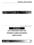
DISTRIBUTION AMPLIFIERS
MANUAL PART NUMBER: 400-0377-004
DA1957CT
1-IN, 4-OUT TWISTED PAIR
DISTRIBUTION AMPLIFIER
USER’S GUIDE
DISTRIBUTION AMPLIFIERS
TABLE OF CONTENTS
Page
PRECAUTIONS / SAFETY WARNINGS ............... 2
GENERAL..........................................................2
INSTALLATION .................................................2
CLEANING.........................................................2
FCC NOTICE .....................................................2
ABOUT YOUR DA1957CT ....................................... 3
TECHNICAL SPECIFICATIONS ............................. 3
PRODUCT DESCRIPTION ...................................... 5
APPLICATION DIAGRAMS...................................... 6
DIAGRAM 1: TYPICAL SETUP ..........................6
DIAGRAM 2: INTERNAL VIEW ..........................7
INSTALLING YOUR DA1957CT.............................. 8
OPERATION............................................................... 8
TROUBLESHOOTING GUIDE ................................ 8
LED IS NOT RED ...............................................8
LED IS NOT GREEN ..........................................9
NO SOUND........................................................9
NO REMOTE IMAGE .........................................9
REMOTE IMAGE QUALITY IS POOR ................9
ALTINEX POLICIES ................................................ 10
LIMITED WARRANTY/RETURN POLICIES.....10
CONTACT INFORMATION ..............................10
400-0377-004
1
DISTRIBUTION AMPLIFIERS
PRECAUTIONS / SAFETY WARNINGS
1.4 FCC NOTICE
1
•
Please read this manual carefully before using your
DA1957CT. Keep this manual handy for future
reference. These safety instructions are to ensure
the long life of your DA1957CT and to prevent fire
and shock hazards. Please read them carefully and
heed all warnings.
1.1 GENERAL
•
•
Qualified ALTINEX service personnel or their
authorized representatives must perform all
service.
1.2 INSTALLATION
•
Place the DA1957CT on a flat, level surface in a
dry area away from dust and moisture.
• To prevent fire or shock, do not expose this unit
to water or moisture. Do not place the
DA1957CT in direct sunlight, near heaters or
heat-radiating appliances, or near any liquid.
Exposure to direct sunlight, smoke, or steam
can harm internal components.
• Handle the DA1957CT carefully. Dropping or
jarring can damage internal components.
• To turn off the main power, be sure to remove
the adapter from the wall. The power outlet
socket should be installed as near to the
equipment as possible, and should be easily
accessible.
• Do not pull the adapter or any cable that is
attached to the DA1957CT.
• If the DA1957CT is not used for an extended
period, disconnect the adapter from the wall to
avoid fire, shock, and loss of power.
1.3 CLEANING
•
•
Unplug the DA1957CT power adapter before
cleaning. Clean surfaces with a dry cloth. Never
use strong detergents or solvents, such as
alcohol or thinner. Do not use a wet cloth or
water to clean the unit.
400-0377-004
2
This device complies with Part 15 of the FCC
Rules. Operation is subject to the following two
conditions: (1) This device may not cause
harmful interference, and (2) this device must
accept any interference received, including
interference that may cause undesired
operation.
This equipment has been tested and found to
comply with the limits for a Class A digital
device, pursuant to Part 15 of the FCC Rules.
These limits are designed to provide reasonable
protection against harmful interference when the
equipment is operated in a commercial
environment. This equipment generates, uses,
and can radiate radio frequency energy and, if
not installed and used in accordance with the
instructions found herein, may cause harmful
interference to radio communications. Operation
of this equipment in a residential area is likely to
cause harmful interference in which case the
user will be required to correct the interference
at his own expense.
Any changes or modifications to the unit not
expressly approved by ALTINEX, Inc. could void
the user’s authority to operate the equipment.
DISTRIBUTION AMPLIFIERS
ABOUT YOUR DA1957CT
2
TECHNICAL SPECIFICATIONS
DA1957CT
1-In, 4-Out Twisted Pair Distribution
Amplifier
FEATURES/
DESCRIPTION
3
DA1957CT
GENERAL
Inputs
The DA1957CT is a 1-In, 4-Out Twisted Pair
distribution amplifier designed to connect a single
ALTINEX Twisted Pair transmitter to as many as 4
ALTINEX Twisted Pair receivers. The DA1957CT
will pass computer video and audio signals from
the transmitter over Twisted Pair-type (CAT-5)
cable.
Input Connector
Outputs
Output Connectors
RJ-45 female (4)
Compatibility
ALTINEX Standard for
Twisted Pair
VGA through UXGA
Video Signal Resolutions
480p through 1080i
VGA:
640x480@60Hz
Recommended Max.
900 ft (274 m)
Cable Lengths
XGA: 1024x768@60Hz
Note: Measurements
700 ft (213 m)
made using ALTINEX SXGA: 1280x1024@60Hz
650 ft (198 m)
low-skew cable,
UXGA: 1600x1200@60Hz
CB3150PV.
600 ft (183 m)
Accessories Included
Signal Types
A typical setup allows a single computer's video
and audio sources to be connected to as many as
4 Twisted Pair receivers. In turn, each receiver
connects to a video monitor, projector etc. and/or
an audio device such as a speaker or amplifier.
ALTINEX compatible transmitters and receivers
include the DA1930CT Video+Audio Twisted Pair
Transmitter and the DA1931CT Video+Audio
Twisted Pair Receiver.
The DA1957CT is capable of equalizing the
attenuation effects of very long cable runs
depending upon the type and quality of cable being
used. Additionally, there is a Signal Detect feature
which shows when an input signal is present.
Power Adapter
Table 1. DA1957CT General
The latest generation of Twisted Pair devices uses
an innovative, patented technology* developed by
ALTINEX. The new signal processing technology
allows transmitting and receiving fully equalized
computer video signals, stereo, and audio signals
over long distances.
* US Patent 7,065,190
400-0377-004
RJ-45 female (1)
3
+9 VDC, 1.1 A
DISTRIBUTION AMPLIFIERS
MECHANICAL
Material
DA1957CT
ELECTRICAL
Input Video Signal
0.1” Al
Finish
Gray
CAT-5/6 Twisted Pair
Top Panel
Lexan
Impedance
Height
1.0 in (25 mm)
Output Video Signals
Width
4.3 in (109 mm)
CAT-5/6 Twisted Pair
Depth
3.0 in (76 mm)
Weight
0.42 lb (0.19 kg)
Ship Weight
0.84 lb (0.38 kg)
T° Operating
10°C-35°C
T° Maximum
50°C
Humidity
MTBF (calculations)
Video/Sync/Audio Signals
ALTINEX Standard
50 ohms
Video/Sync/Audio Signals
ALTINEX Standard
Impedance
50 ohms
Power Consumption
External Adapter: 9 VDC
Table 3. DA1957CT Electrical
90% non-condensing
40,000 hrs
Table 2. DA1957CT Mechanical
400-0377-004
DA1957CT
4
670 mA (6.0 W)
DISTRIBUTION AMPLIFIERS
PRODUCT DESCRIPTION
4
POWER/SIGNAL
PRESENT LED
TP OUTPUTS
TP INPUT
VIDEO
EQUALIZATION
POWER
400-0377-004
5
DISTRIBUTION AMPLIFIERS
APPLICATION DIAGRAMS
5
DIAGRAM 1: TYPICAL SETUP
DA1930CT
DA1957CT
DA1931CT
DA1931CT
DA1931CT
DA1931CT
400-0377-004
6
DISTRIBUTION AMPLIFIERS
DIAGRAM 2: INTERNAL VIEW
INPUT
OUTPUT
TWISTED PAIR
RJ-45
HW
OUTPUT 1
EQ
OUTPUT 2
TWISTED PAIR
INPUT
RJ-45
OUTPUT 3
OUTPUT 4
POWER SUPPLY
+9 VDC
1.1 A
2.5mm
400-0377-004
POWER
SUPPLY
SIGNAL
DETECT
7
DISTRIBUTION AMPLIFIERS
INSTALLING YOUR DA1957CT
6
OPERATION
Step 1. Determine the best location for the
DA1957CT.
There is an equalization
adjustment on the DA1957CT that will
affect all the distributed signals.
Therefore, place the DA1957CT as
equidistant to all receivers as possible.
7
The DA1957CT will operate successfully as long as
cables are attached properly and other technical
specifications are followed. The only adjustment on
the DA1957CT is for video equalization and only
needs to be made at the time of installation.
Video equalization is provided to fine-tune the
displayed image on the remote display. The
equalization knob is a single-turn adjustment. At
minimum (fully CCW), the arrow points to the 7
o'clock position and at maximum (fully CW) it
points to the 5 o'clock position.
Step 2. Connect the power adapter to the
DA1957CT and plug it into the power
outlet. The power indicator LED on the
front panel will light red. This indicates
that the unit is operational.
Step 3. Connect a cable from the Twisted Pair
transmitter to the Input connector on the
DA1957CT. The LED should turn green
indicating a signal is present.
TROUBLESHOOTING GUIDE
Step 4. Connect 1 to 4 of the DA1957CT outputs
to Twisted Pair receivers. The unused
outputs (if any) do not need to be
terminated.
8.1 LED IS NOT RED
We have carefully tested the supplied DA1957CT
unit and have found no problems; however, we
would like to offer the following suggestions:
The LED should be on and red when power is
applied and there is no video signal present. If
the LED is on and green, the unit is receiving
power and a sync signal.
Step 5. Connect the receiving devices (monitors,
projectors, speaker, etc.) to Twisted Pair
receivers per the instructions found in
their manuals.
Step 6. Adjust the equalization setting for the best
image quality. This normally requires 2
people; one at the transmitter and one at
the receiver to adjust the receiver and
view the image.
400-0377-004
8
8
Cause 1:
There is no AC power.
Solution:
Verify the adapter is plugged into a
working AC outlet, and that the
outlet has power. Only use the
ALTINEX-provided power adapter.
Cause 2:
The adapter is not connected.
Solution:
Verify the DC power plug coming
from the AC adapter is plugged all
the way into the DA1957CT.
Cause 3:
The DA1957CT has a problem.
Solution:
If there is AC power to the adapter
and the LED still does not turn on,
the DA1957CT or the power adapter
may require service, call ALTINEX
at (714) 990-2300.
DISTRIBUTION AMPLIFIERS
8.2 LED IS NOT GREEN
Cause 1:
There is no power.
Solution:
Disconnect the video input from the
DA1957CT and verify the LED is on
and red indicating power is present.
Reconnect the computer's video
output. If the LED is still not green,
see Cause 2.
Cause 2:
Cause 4:
The receiving device is bad.
Solution:
Make sure the receiving device has
power and is turned on. If there is
still no sound, please call ALTINEX
at (714) 990-2300.
8.4 NO REMOTE IMAGE
There is no sync signal.
Solution 1: Verify the computer output is
operating correctly by connecting it
directly to a local monitor. If the
display is good, see Solution 2.
Solution 2: Verify that the transmitter and
receiver are each operating correctly
by connecting them directly to each
other, bypassing the DA1957CT. If
the display is good, see Solution 3.
Solution 3: Reconnect the DA1957CT. If the
Power/Signal Present LED is on and
red with a signal, call ALTINEX at
(714) 990-2300.
Cause 1:
The source has a problem.
Solution:
Check the image on the local
monitor and verify the quality is
good. If the local image is good, see
Cause 2.
Cause 2:
Video equalization is required.
Solution:
Adjust the Video Equalization on the
DA1957CT. Long cable runs may
require adjustment. In general,
cable runs less then 50 ft (15 m)
require little or no video equalization
and should be set to minimum. If
there is still no image, see Cause 3.
Cause 3:
There is no signal.
Solution:
If the Power/Signal Present LED is
on and green and there is still no
image,
call
ALTINEX
at
(714) 990-2300.
8.3 NO SOUND
Cause 1:
The source has a problem.
Solution:
Check the source and make sure
that there is a signal present and all
source connections are correct. If
the source is working and there is
still no sound, see Cause 2.
Cause 2:
The volume is too low.
Solution:
Increase the Audio Gain on the
transmitter toward maximum. If
there is still no sound present, see
Cause 3.
Cause 3:
Cable connections are incorrect.
Solution:
Make sure that cables are properly
connected. Also, make sure that the
continuity and wiring are good. If
there is still no sound, see Cause 4.
400-0377-004
8.5 REMOTE IMAGE QUALITY IS POOR
9
Cause 1:
The source has a problem.
Solution:
Check the image on a local monitor
and verify the quality is good. If the
local image is good, see Cause 2.
Cause 2:
Video equalization is required.
Solution:
Adjust the Video Equalization on the
DA1957CT. If the image is still not
correct,
call
ALTINEX
at
(714) 990-2300.
DISTRIBUTION AMPLIFIERS
ALTINEX POLICIES
9
9.1 LIMITED WARRANTY/RETURN POLICIES
Please see the ALTINEX website at
www.altinex.com for details on warranty and
return policies.
9.2 CONTACT INFORMATION
ALTINEX, Inc.
592 Apollo Street
Brea, CA 92821 USA
TEL: 714 990-2300
TOLL FREE: 1-800-ALTINEX
WEB: www.altinex.com
E-MAIL: [email protected]
400-0377-004
10