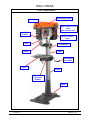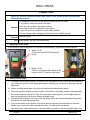
1
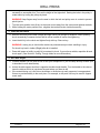
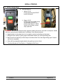
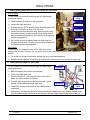
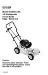
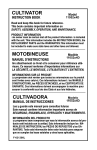
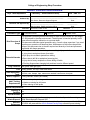
College of Engineering Shop Procedure
DRILL PRESS PROCEDURE
Dept: Multi-department
Authored by:
Laboratory: Student Machine Shop
________________________________________
Rm: HML 112
____________
Dick Sevier, Research Support Engineer
Reviewed and Approved by:
________________________________________
Date:
____________
Matt Lundgren, EH&S Lab Safety Officer
Filename:
Procedure Type
Brief Overview &
Scope
Potential Hazards
Engr. Controls
PPE
Add'l Equipment,
Tools:
Mat’ls, Supplies:
Add’l Training
Requirements
Drill Press 17-Oct-11.doc
Process/Protocol
Chemical
Date:
Revision:
1
Hazard Class
This procedure provides general instructions on how to use the Wilton 20" and Ridgid
14" drill presses in the shop environment. The drill press is intended primarily to drill
holes either through the material or to a pre-set depth.
This document describes typical operations only; consult a shop supervisor if you need
to perform an operation not described here. Maintenance of the tool are beyond the
scope of this document due to the skill required and diversity of tools and processes
associated with these operations.
•
•
•
•
•
•
Entanglement with chuck or belt system resulting in injury or death.
Injury due to workpiece thrown from table.
Eye injury due to debris ejected from drilling.
Burns due to drill bit or workpiece becoming hot.
Injury due to heavy workpiece or fixture falling off table
Pinching fingers when changing belt positions to set to different speed
Belt guard, work light (opt.)
Safety glasses, non-slip, close-toed shoes
Drill bits, vise, clamps, taps, reamers as needed, hand broom, dust pan
Cutting lubricant, towels (as needed)
• All mandatory shop training modules
• Hands-on training for drill press
• Video training for drill press
Special Requirements:
Handling &
n/a
Facilities
Spill & Incident
Decontamination/
Waste Disposal
Sources/
References
n/a
Any paper towels, rags or other waste generated is to be disposed of according to
Shop Waste Materials Disposal SOP.
Some content for this procedure have been taken from the user manual for the Ridgid
DP15501 drill press and the UCLA Student/Faculty Shop online drill press training.
DRILL PRESS
TABLE OF CONTENTS
TOOL COMPONENTS .................................................................................................................... 3
GENERAL DRILL PRESS SAFETY RULES .................................................................................. 4
COMMON TASKS .......................................................................................................................... 5
1. Stopping the Drill Press .......................................................................................................... 5
2. Setting Chuck Speed ............................................................................................................... 5
3. Insert Bit Into Chuck................................................................................................................ 6
4. Set Table Height ...................................................................................................................... 6
5. Fixturing Workpiece ................................................................................................................ 7
6. Drilling Through Holes ............................................................................................................ 8
7. Setting Drilling Depth and Quill Return- Wilton 20" Drill Press............................................ 9
8. Setting Drilling- Ridgid 14" Drill Press ................................................................................... 9
9. Tilting Table ........................................................................................................................... 10
10. After Using the Tool .............................................................................................................. 10
17-Oct-11
Page 2 of 10
DRILL PRESS
TOOL COMPONENTS
Depth Stop
Belt/Pulley Guard
Motor Position Lock
Bolt
(one on each side)
On/Off
Switch
Motor Position
Lever
Quill
Feed Handle
Rack
Chuck
Table Height
Adj. Handle
Table
Column
Table Lock
(opposite
handle)
Base
17-Oct-11
Page 3 of 10
DRILL PRESS
GENERAL DRILL PRESS SAFETY RULES
a. Safety glasses are required to use this tool.
b. .To prevent entanglement with the chuck or bit:
- Tie back long hair and tuck under shirt, roll up long sleeves, remove gloves or loose clothing.
- Remove any gloves, rings, or other jewelry.
- Keep hands away from work area.
- Do not slow or stop the chuck with your hand after powering off. Let the machine stop by itself
before touching the chuck or drill.
c. Know the location of start and stop switches or buttons.
d. Do not use any machine in which a guard or cover has been removed. Contact the shop supervisor
immediately.
e. Be sure to remove the key from chuck before turning the machine on.
f.
Keep the drill press table free of tools and other materials; cluttered areas can lead to accidents
g. All stock must be properly secured with a vise or clamps prior to a machining process.
h. All belts and pulleys must be guarded; if frayed belts or pulleys are observed, the drill press must be
taken out of service and the belts or pulleys must be replaced.
i.
Use only properly sharpened drill bits, sockets and chucks in good condition. Bring dull drill bits,
battered tangs, or sockets to supervisor.
j.
Do not remove metal or wood chips by hand from the table or stock. Use brushes or other tools to
properly remove chips.
k. Do not attempt to make adjustments to the workpiece while the drill press is in motion.
l.
If the stock slips in the vise or clamp, the operator must not attempt to hold the work with his/her hand
or try to tighten the vise/clamp while the machine is in motion. Shutdown the power to the machine
prior to re-tightening the loose stock.
m. Use the correct speed, drill and lubricant for the type of stock being machined. Ask a supervisor for
help if you don't know.
n. Use the appropriate bit for the stock being machined.
o. Never attempt to remove a broken drill from your work piece with a center punch or hammer, as it
may shatter.
p. If any part of your drill press malfunctions or has been damaged or broken, notify the supervisor
immediately.
q. If you have any questions about this tool or its use, stop what you are doing and ask a shop
supervisor.
17-Oct-11
Page 4 of 10
DRILL PRESS
COMMON TASKS
Hazard, EC and PPE information listed below applies to the following tasks and sub-tasks
unless otherwise noted.
• Entanglement with chuck or belt system resulting in injury or death.
• Injury due to workpiece thrown from table.
• Eye injury due to debris ejected from drilling.
Hazards
• Burns due to drill bit or workpiece becoming hot.
• Injury due to heavy workpiece or fixture falling off table
• Pinching fingers when changing belt positions to set to different speed
Engineering
Belt/pulley guard
Controls
PPE Safety glasses, non-slip, close-toed shoes
1. Stopping the Drill Press
In the course of normal operation or in the event of an emergency, stop the drill press as shown:
a. Wilton 20" DP:
Firmly press the red STOP button (left
figure).
b. Ridgid 14" DP:
Press the red power paddle switch at the
bottom to the OFF position (right figure).
2. Setting Chuck Speed
c. To properly set your chuck speed, you need to know the material you are cutting and the diameter of
your cutting tool (drill bit). Note: these speeds apply to drilling only, not reaming, tapping or specialty
operations.
d. Consult a cutting speed chart in the shop and calculate the desired chuck speed.
e. The chuck speed is determined by the location of the belts on the pulleys inside the head assembly.
f.
Be sure the machine is turned off. Open the belt guard on the drill press. On the Ridgid drill press,
push the grey button on the front to release the guard's latch.
g. The speed chart located on the inside of the belt guard shows the recommended speed and pulley
configuration for each drilling operation.
h. To move the belts to a new position, first loosen the motor position lock bolts and turn the motor
position lever to move the motor towards the column. This will relieve belt tension.
i.
Look at the chart, noting which pulley is the motor pulley and which is the chuck spindle pulley. One
17-Oct-11
Page 5 of 10
DRILL PRESS
will be higher than the other when set. Set the position of the lowest belt first. Remove the other belt if
necessary to accomplish this. Then set the height of the higher belt. Seating the belts in the pulley is
made easier by turning the pulleys by hand.
WARNING: Keep fingers away from the area in which the belt and pulley come in contact to prevent
pinch injuries.
j.
Turn the motor position lever firmly so the motor moves away from the column and tightens the belts.
k. While holding the motor position lever, retighten the two belt tension lock bolts securely
3. Insert Bit Into Chuck
a. Remove chuck key from holder (Ridgid) and open chuck just enough to accept bit. Note: Opening
chuck excessively increases chance that bit will be located off center after tightening.
b. Insert the bit fully in the chuck and tighten firmly with key. Remove key.
WARNING: Leaving key in chuck while machine is powered can eject chuck resulting in injury.
Put chuck key back in holder (Ridgid) after bit is installed.
c. Power drill press on briefly to verify bit is centered in chuck. If you notice a wobble, reposition bit and
check again. (See Section 6. Drilling Through Holes for more information.)
4. Set Table Height
a. Consider whether you will need a vise to hold your workpiece or if you will clamp directly to table. (this
is described in more detail below).
b. Unlock the table support lock that is opposite the table height handle. Turn the handle to the raise or
lower the table so the bit is just above the point where you want to drill.
c. If the material being cut is not flat on the bottom or otherwise not easily supported, use appropriate
fixtures to provide stability to the work piece. For example, a drill press vise may be used to support
round stock.
17-Oct-11
Page 6 of 10
DRILL PRESS
5. Fixturing Workpiece
Improperly fixtured workpieces are a major source of accidents when using a drill press. It is impossible to
describe the best way to fixture a piece when using the drill press. Improperly fixtured workpieces can get
spun at high speed by the drill press, resulting in injury. However, the information below should provide
important considerations as how best to fixture the piece.
Problems arise when drilling large diameter holes, drilling thin stock that is hard or when the workpiece is
irregularly shaped on the bottom.
Please ask a shop supervisor if you are unsure how to fixture your work.
a. Backing Material
When drilling though holes, place some scrap material to space your workpiece off of the drill press
table or vise. That way, when the drill bit comes out the bottom of the workpiece, it will not drill into
the table or vise. Factor this material into your workpiece fixturing work.
WARNING: Failure to properly fixture large or irregularly shaped workpieces can result in workpiece
shifting or moving while being drilled. This can lead to the workpiece falling off the table, breaking drill
bits or workpiece being ejected from the table. See instructions below.
b. Large Pieces
Large pieces may be clamped directly to the drill press table. If the hole to be drilled is small (<.25"),
no clamping may be required, as the mass of the workpiece will prevent it from rotation.
c. Irregularly Shaped Workpiece
An irregularly shaped workpiece is difficult to clamp since it may not have a flat, stable surface to
present to the table. These workpieces may require a separate tooling or custom fixture to hold it to
the table. Consult with your shop supervisor as needed.
WARNING: Failure to properly fixture small or thin workpieces can allow the bit to catch on it, resulting in
a spinning workpiece. This can lead to injury or ejection of workpiece. See instructions below.
d. Small Stock or Round Stock
Small or round stock can be clamped in the vise. If you are drilling a large diameter hole (0.25" or
larger), clamp the vise to the drill press table.
e. Thin stock
Thin stock such as shim stock can prevent special problems, particularly if the material is hard or
difficult to drill. Often, they can't be clamped in the vise because they bend in the jaws. Clamp thin
stock directly to the table or sandwich it in thicker materials and then clamp the assembly to the table
or in vise.
17-Oct-11
Page 7 of 10
DRILL PRESS
6. Drilling Through Holes
a. Turn drill press on.
i. Wilton 20" DP:
Firmly press the green START
button (left figure).
ii. Ridgid 14" DP:
Pull the red power paddle switch
at the bottom to the on (1)
position (right figure). If yellow
switch key is missing, contact
shop supervisor.
WARNING: Failure to use lubricant and/or aggressive drilling will result in a hot drill or workpiece. Handle
with care, using a towel to handle piece if necessary. See instructions below.
b. Apply lubricant to site where hole is to be made to reduce heat buildup and tool wear.
c. Bring quill down slowly by pulling upper feed handle towards you and begin drilling hole.
d. Back the drill out frequently to allow chips to be cleared from hole, then begin drilling again. Repeat
until hole is completed.
e. When drill has passed through material, bring quill up and out of hole.
f.
Turn the drill press off. See Section 1. Stopping the Drill Press.
17-Oct-11
Page 8 of 10
DRILL PRESS
7. Setting Drilling Depth and Quill Return- Wilton 20" Drill Press
Drilling Depth:
To drill a blind hole (not all the way through) to a given depth,
proceed as follows.
a.
Stop Lock
Ring
Mark the depth of the hole on the workpiece.
b. Loosen the depth scale lock.
Stop Ring
c. With the switch in STOP position, bring the drill bit down until
the tip of lip of the bit are even with the mark.
QuillStop
d. Loosen the two rings above the stop. Spin the lower ring to
the position where you want the quill to stop. Bring the quill
down to double-check position. Set the stop ring by spinning
the lock ring against it.
Return Ring
e. Quill motion will not be stopped when the lower stop ring
contacts the quill stop. The drill bit will stop at this depth until
the depth stop rings are readjusted.
Quill Return:
In most cases, it is desirable for the quill to fully return to the
highest point of travel. However, you can set the quill so that it does not fully return to the uppermost
position.
a. To set the ring, bring the quill down and spin the ring in the desired position.
b. Double check the position by allowing the quill to return until the return ring contacts the quill stop.
8. Setting Drilling- Ridgid 14" Drill Press
To drill a blind hole (not all the way through) to a given depth,
proceed as follows.
Indicator
a. Mark the depth of the hole on the workpiece.
b. Loosen the depth scale lock.
c. With the switch OFF, bring the quill down until the bit is
where you want it relative to the mark.
d. Turn the depth scale ring counterclockwise until it stops
moving. Finger tighten the depth scale lock.
e. The drill bit will stop at this depth until the depth scale is
readjusted.
f.
Depth Scale
Depth Scale
Lock
Alternatively, the depth can be set by simply loosening the depth scale ring, bringing the quill down
until the desired depth is indicated on the indicator and then finger tightening the depth scale lock.
17-Oct-11
Page 9 of 10
DRILL PRESS
9. Tilting Table
To use the table in a bevel (tilted) position:
a. Loosen the set screw under table bevel lock with hex
key. Loosen table lock bolt with the hex box wrench
(included).
b. Tilt table to desired angle by reading bevel scale.
Retighten bevel lock and set screw.
WARNING: To reduce the risk of injury from spinning
work or tool breakage, always clamp workpiece and
backup material securely to table before operating drill
press with the table tilted.
Table Lock
Bolt
Bevel Scale
Table Set
Screw
To return table to original position:
c. Loosen set screw and bevel lock, tilt table back to 0°
on bevel scale and retighten set screw, then tighten
bevel lock. Put long bit in chuck and verify it is
perpendicular to table with a square.
Square
10. After Using the Tool
a. Wipe table clean and sweep up chips and debris off the floor.
b. Return any clamps, etc. used for fixturing to their proper place.
c. Be sure chuck key is returned to its proper place.
d. Wipe bit(s) clean and put back in the proper place.
e. Turn off drill press light if used
f.
Make sure the table is set at the horizontal position so it is ready for the next user. Restore any other
settings to their nominal positions as needed.
g. Shop towels to be disposed of in accordance with the Shop Waste Disposal SOP.
17-Oct-11
Page 10 of 10