1
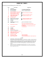
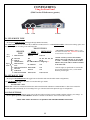
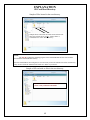
Satellite TV
Nomad
SD/SD2
USER GUIDE
Software Version 100 or higher
ALL RIGHTS RESERVED
901-Nomad SD/SD2 Manual
Rev 2 August 2011
2
TABLE OF CONTENTS
DEFINITIONS
FEATURES
FRONT VIEW
REAR VIEW
OPERATION
Testing the Dish
Finding Satellite
Stowing the Dish
SD Memory Cards
Firmware Upgrade
Log Files
Error Message Definition
ERROR CODES
PROGRAMMING (CONFIGURATION)
SETTING SERVICE AND MOUNT TYPE
SHOW MODE SETTINGS
ROOT DIRECTORY EXPLANATION
MOUNT COMPONENTS
SENSORS
WIRE SCHEMATIC
MOUNT CLEARANCE
3
4
5
6
7
8
10
11
11
12
13
14
15
16
17
MOUNT ROTATIONAL DEFINITIONS
ELEVATION
Raising from the stowed position.
AZIMUTH
Rotation of the mount on the base
SKEW
Rotating or tilting of the dish from side to side
STOW
Travel position
COMPONENT AND FUNCTIONAL DEFINITIONS
Mount – Consisting of the dish and the mechanics to move the dish
Nomad SD2 - Positioner, Controller or Control Box
LNB – The device in front of the dish that receives the satellite signal
Control Cable – The 9 conductor cable that connects the Mount to the Nomad SD2
SD Card – The data storage device which provides software and configuration updates
Azimuth Motor – The motor on the mount that controls azimuth movement
Elevation Motor – The motor on the mount that controls elevation movement
Skew Motor – The motor on the mount that controls skew movement
Scotch Locks – The devices used to splice electrical wires within the mount assembly
BLUE LIGHT – The illumination of the dish face that signifies MotoSAT quality and excellence
LED – The lights on the front panel of the Nomad SD2 that indicates system status
Software – Code which instructs the mount to move, locate and identify satellites
Configuration – The instruction that tells the mount which satellites to identify. This can be accomplished from either from either
the front panel or with the use of the SD card
Log Files - Diagnostic files stored on the SD card for monitoring the system as it goes through its various routines
4
FEATURES
The Nomad SD and SD2 Controller have many features that make finding satellites simple and fast. All of the satellite
pointing and identification is taken care of by the Nomad SD and SD2 Antenna and Controller. After your controller has been
installed and configured, push the “POWER” ON button followed by the “FIND” button (to put your antenna into “search” for
satellites mode) and your system will do all the work. To stow the system for travel, press the “STOW” button to bring your antenna
into the stowed (travel) position Your Nomad SD and SD2 Controller(s) have many features that will assist you in acquiring and
identifying satellites. Here are some of them:
• Fully configurable through the front panel or optional .dat file (see Programming Using the Front Panel in this
manual.)
• Software upgrades can be done using the SD Memory Card provided with your controller (see Programming Using
the SD Card in this manual.)
• Controller and Mount operate on 12 VDC with less than 3 amp draw during movement..
• Controller automatically shuts itself off when the antenna is stowed.
• New software is automatically detected and loaded into non volatile memory within 15 seconds after power ON
when an SD Memory Card (containing new upgrade file) is placed into the controller (see Firmware Upgrade for
instructions.)
• The Nomad SD/SD2 Controller may be configured to operate any open faced TV system MotoSAT manufactures.
• Controller may be configured to select satellites serving DirecTV, Dish Network, SHAW Direct and Bell TV.
• GPS option may be added to assist in satellite quicker acquisition.
The Nomad SD/SD2 contains Operational Features such as:
• Three (3) button operation, POWER, FIND and STOW.
• LED Display to indicate LNB power, FIND, STOW and POWER status.
• Error Coded displayed through blinking “FIND” LED.
• Automatic STOW feature on every system…… it is called “the first overpass”. Just checking to see if you are
reading the manual (smile.)
• Ability to take advantage of improvement software upgrades by going directly to www.motosat.com and
downloading the latest firmware upgrade for use in your system.
• Return to Last Satellite. This feature eliminates the blind search that is required when you have moved to a new
location. Once the system has located the satellite(s), it will return to that location after you have stowed then repowered the system. This operation will reduces acquisition time.
• Your open faced MotoSAT antenna is highlighted (noticeable at night) with a soft glow from a blue LED on the
mount.
• No accidental deploying of the system. Power must be turned ON and then you must select either FIND or STOW.
The “FIND” button puts the antenna into satellite acquisition mode. The “STOW” button retracts the antenna for
traveling.
• The antenna stows to a height of 10 ½ inches (below your air conditioner height.)
• A mounting plate that attaches to your roof will disperse the wind loading created by the antenna during wind gusts.
• All of the electronics that control the antenna are located inside your RV.
• The Nomad Controller runs independent of the satellite receiver. In other words it does not rely upon interaction of
the satellite receiver to find satellites.
5
FRONT VIEW
STOW FIND SD Card
Status Indicators
Power
The Front Panel consists of three buttons; “STOW”, “FIND” and “POWER.” It also has 4 LED indicators; STOW, FIND, LNB and POWER.
BUTTONS
STOW: This button will return the dish to the “STOWED” position for travel. It also works in conjunction with the FIND button to put
the unit into “Test Dish Mode.”
FIND: This button will start the Nomad SD/SD2 searching for satellite(s). It also works in conjunction with the STOW button to put the
unit into “Test Dish mode.”
POWER: This button turns the power to the Nomad SD/SD2 ON and OFF.
LED’s
STOW: When the Nomad SD/SD2 Controllers are in Test Dish mode or in the process of stowing the dish, this LED indicator blinks. It is
on continuously when a dish is properly stowed.
FIND: When the Nomad SD/SD2 is searching for a satellite, this LED indicator will blink. When this indicator is ON continuously, the
Nomad SD/SD2 has completed its search and is locked onto satellite(s).
LNB: When the controller is searching for satellites this LED is ON. The power is supplied to the LNB by the Nomad SD/SD2 Controller
during this time. Once the controller has locked onto the satellite(s), the LNB receives its power from the satellite receiver if the
satellite receiver is linked to the mount through the Nomad SD/SD2 (this link is optional.)
Power: This LED indicates to the user that the Nomad SD/SD2 Controller is ON.
SD Card Slot
This card slot permits the use of either a Multimedia Card (MMC) or a Secure Digital Card (SD). To insert the card, push it into the slot
until you feel a detent or hear a click. To remove the card, push in on the card until you feel or hear a click indicating that the card has been
released then slide the card out of its slot. SD Cards DO NOT have to be installed the SD Card slot for proper operation of the system. The
SD cards used for loading Controller software upgrades and/or capturing Log data
6
REAR VIEW
12 VDC
Control Cable
To Receiver To Mount
The Rear Panel consists of a MAIN POWER and CONTROL CABLE connector, TO RECEIVER and TO MOUNT FConnectors. The Nomad SD Controller differs from the Nomad SD2 in that the SD Memory Card Slot is located in the rear of the unit
between the Control Connector (9 pin) and the “To Receiver” F-type connector.
CONNECTIONS
12 VDC: Provides +/- 12 volt DC input power for Controller and
Mount operation.
Control Cable: Sends +/- 12 volt DC power to the Mount motors and
receives positioning information from the dish.
To Receiver: This cable routes the TV signal to the Satellite Receiver (see the label on the bottom of the Controller.)
To Mount: This cable routes to the Roof Mount to provide LNB power (see the label on the bottom of the Controller.)
NOTE: For DirecTV 5 LNB Slim Line High Definition receivers that require a B-Band Converter (BBC), install it
before the Controller.
For Dish Network receivers that use a Separator, install it after the controller.
7
OPERATION
POWERING UP the Nomad SD /SD2 Controller
After making the entire antenna, controller and receiver connections for the Nomad SD/SD2, press the POWER button. The unit will
initiate its self test routines which take only take a few seconds to complete. The FIND, STOW, and LNB LED’s will illuminate momentarily during
this process. Once the initialization test routine has finished, the front panel LED display will indicate the status of the dish. The “FIND” and
“POWER” LED’s will be illuminated if the dish is locked on the designated satellite(s). If the “STOW” and “POWER” LED’s are illuminated, the
dish is in the stowed (travel) position. If the “LNB” LED is illuminated, the satellite receiver is connected to the controller and has power applied to
it. If the dish status is unknown, neither the “FIND” nor “STOW” LED’s will be illuminated. In this case either press “STOW” to stow the dish or
perform a Test Dish before proceeding.
TEST DISH or testing the Mount
First time operation of the Nomad SD/SD2 controller requires the user to execute a “Test Dish.” This will “marry” the controller to the
mount. To execute a Test Dish routine, turn the POWER ON and depress the STOW and FIND buttons simultaneously. The controller will perform
a full test dish operation and determine the type of mount to which it is connected. The “STOW” LED will flash during this operation. Once the “Test
Dish” operation has completed, the dish will be in the stowed position and the “STOW” LED will be illuminated continuously. If the mount type
conflicts with the current network configuration, a critical error will be displayed by the flashing FIND LED. The number of blinks will indicate the
type of error encountered. See ERROR CODES in this manual. Two minutes after the completion of a “Test Dish” operation if there is no other
activity, the Nomad SD/SD2 will shut itself down (turn the POWER OFF automatically.
FINDING a Satellite
Turn the POWER ON and wait for the controller to power up then press the FIND button once. The dish will read GPS data (if installed),
and begin searching for the desired satellite(s) as defined by the network configuration (Satellite TV Provider Satellites) or Return to Last Know
Satellite(s) location. The FIND LED will flash during this time. Once the controller has locked onto the desired satellite(s), the FIND LED will be
illuminated continuously.
If you press the “FIND” button and then press it again and hold it in for 3 seconds this will bypass the Return to Last Known Satellite
routine or if the GPS has failed to provide a reliable location to the controller, the dish will perform a regular search routine.
STOWING the Dish
To stow the dish (place it into the travel position (fully retracted)) press the “STOW” button once and the controller will begin to return the
dish to the travel position. The STOW LED will flash while stowing. The “STOW” button can be pressed anytime during the search for and after
locking onto a satellite(s). Once the dish is stowed, the controller will shut itself down automatically.
SD MEMORY CARDS
The system will operate properly with or without a memory card inserted. The card has two Functions.
1. Upgrading the latest firmware (obtained from www.motosat.com ) when it is placed into the Root Directory.
2. Create and record data (LOGFILES) which will aid in troubleshooting the system if an error should occur. This file folder is
automatically created or added to each time the system is put into operation.
The card is inserted by pushing the card into the slot until it clicks into place. To remove the card, depress the card once again
and the socket will eject it then slide the card out of the memory slot. The SD Card must be formatted to a FAT32 file format.
STEPS TO PERFORM A FIRMWARE UPGRADE
1. Stow the dish before beginning this upgrade procedure.
2. The Nomad SD/SD2 Controller(s) can be upgraded manually by copying the latest firmware upgrade into the Root
Directory. See EXPLANATION of SD Card Root Directory in this manual. Be sure to copy the file into the card’s
“root directory" and not into a subdirectory or folder. You can find the latest firmware upgrade for the controller on
our web site at: www.motosat.com.
3. Power OFF the controller then insert the memory into the card slot of the controller.
4. Power ON the controller. The Nomad SD/SD2 Controller will automatically detect the upgrade and install the
upgrade code.
During the upgrade process, the FIND and STOW LED’s will flash alternately indicating that programming is taking place. DO NOT
remove the SD memory card from the Controller until upgrade process is completed. Completion of the upgrade is indicated by
8
steady FIND and STOW LED's. If no upgrade is detected or the upgrade attempted has an older version file name than what is
already installed in the controller, an upgrade will not take place.
LOG FILES
Log Files are a diagnostic tool for monitoring the system as it goes through its various routines. The Log Files are created and
automatically copied into the Log Files subfolder on the memory card being used. If there is not a Log Files folder on the memory
card, the Nomad SD/SD2 will create one at initialization. The memory card must not be write-protected (note the slide switch on the
side of the SD Card) for Log Files to be created and stored. If it is write-protected the Nomad SD/SD2 will ignore the card. The most
recent log file entry is the one with the highest incremental number in the file name. To read a log file, insert the memory card into
your computer and open it using Word Pad or any Text Editor. The Controller creates a new Log File when a successful satellite
search is completed, if a system Critical ERROR occurs or after a successful dish stowing operation.
ERROR MESSAGES
The Nomad SD/SD2 has internal diagnostic capabilities that will indicate when a Critical Error has been detected. If a critical
error occurs, the STOW and FIND LED’s will blink simultaneously at one second intervals. The number of repetitions will indicate
the specific number error code number. After a two (2) second pause the Nomad SD/SD2 will blink out the error code number again.
The system can not function after experiencing a critical error. The unit will have to be shut OFF and restarted (see Test Dish.) The
Nomad SD/SD2 will also record a text message indicating the error into the Log File if a memory card was installed at the time of the
error. If the card was not inserted at the time of the error turn OFF the power and insert a memory card and turn ON the power to the
Nomad SD/SD2 and press the “FIND” button. This captured information can be sent to the MotoSAT Technical Support Department
by email to [email protected] to be analyzed.
9
ERROR CODES
Indicated by sequential flashing of the “FIND” LED
Code
0
1
2
3
4
5
6
7
8
9
10
11
12
13
14
15
16
17
Description
NO ERROR
MOTOR, MOVING
INVALID MODE 1
INVALID MODE 2
MOTOR TIMEOUT ELEVATION
MOTOR TIMEOUT AZIMUTH
MOTOR TIMEOUT SKEW
LIMIT ERROR ELEVATION
LIMIT ERROR AZIMUTH
LIMIT ERROR SKEW
TUNER FAILURE
AGC, NO LOCK
MAIN SAT ONLY FOUND
MAIN SAT NOT FOUND
UNUSED
UNUSED
NO SATELLITES FOUND
OVER TEMP
18
DISH HEIGHT ERROR
19
COAX ERROR
20
21
22
23
24
25
26
27
28
29
30
UNUSED
UNUSED
GPS FAILURE
NO MAIN AFTER SKEW
CRITICAL INTERNAL FAILURE
LNB POWER FAILURE
TUNER AMP ON, FAILURE
TUNER ID, FAILURE
MOTOR FAILURE
COUNTER, FAILURE
MOUNT MISMATCH
!
*
**
Suggestions
>> NORMAL OPERATION
CHECK CONFIGURATION
CHECK CONFIGURATION
CHECK SENSORS OR WIRING
CHECK FOR OBSTRUCTIONS,
TREES, BUILDINGS, ETC.
!
!
CHECK FOR OBSTRUCTIONS,
TREES, BUILDINGS, ETC.
CHECK FOR OBSTRUCTIONS
*
ELEVATION SENSOR FAILURE OR
IMPROPER CONFIGURATION SELECTION
FOR MOUNT
REVERSED COAX CABLES ON BACK OF
CONTROLLER
**
!
!
!
!
CHECK SENSORS
CHECK SENSORS
CHECK PROGRAMMING CONFIGURATION
GUIDE
Critical Error – Factory action required.
This code does not necessarily mean that the controller has a problem. It indicates that the
temperature within the working environment has exceeded a normal operational level and
could damage or affect normal operation of your electronic equipment. Correct the over
temperature problem and if problem continues, replace the Nomad controller. This error
means that you have been warned concerning damage to your other electronics in the
cabinet.
Press the FIND button once and then press it again and hold it for 3 seconds. This will bypass
Return to Last Known Satellite location. If the GPS has failed to read it will also bypass the GPS
and do a regular search routine.
10
CONFIGURING
Using the Front Panel
(With Version 29 Software or greater)
STOW
FIND
POWER
To SET SERVICE TYPE
(Pressing the FIND BUTTON will toggle through SERVICE TYPE.)
The FIND LED indicates the Network ID (or SERVICE TYPE) selected. It will blink the number of the current settings, pause, and
the repeat the pattern according to the following table:
SERVICE
TYPE
Slow
Blink
Rapid
Blink
1 Dish Network
MOUNT TYPES
SKEWABLE*
NON
SKEWABLE*
110/119
**SHAW DIRECT CONFIGURING – SIMPLY LOAD
SOFTWARE REVISION nsd_1000.hex OR HIGHER.
CONFIGURING IS AUTOMATIC.
110, 119
2 DirecTV
101
99, 101, 103, 110, 119
82/91
82, 91
3 Bell TV
See “SHAW Direct Configuring”**
SHAW Direct
Dish Network
61.5/110/119
N/A
5
East
N/A
6 Dish Network West 110/119/148
DirecTV
7
101/119
N/A
Enhanced
110, 119, 129
8 Dish Network HD 110/119, 129
*NOTE: A slash (/) between the satellites
indicates the system will only see one satellite
at a time. A comma (,) between the satellites
indicates the system will see all these satellites
at the same time.
Once the eight (8) rapid blinks are reached the
process will start back at one (1) if the FIND
button is pressed again.
To SET MOUNT TYPE
(Pressing the STOW BUTTON will toggle between Skewable and Non-Skewable mount configurations.)
The STOW LED will indicate Skewable or Non-Skewable type mounts
Skewable = ON,
Non-Skewable = OFF.
Please note: In the case of Dish Network EAST, Dish Network WEST and DirecTV ENHANCED or a Star Choice mount the
STOW LED will automatically be set according to the type of mount used for that particular type of configuration.
SAVING SETTINGS
To save the current configuration setting, turn off the unit and turn it back on again normally and that will store your settings. At
this time please perform a TEST DISH to match the Controller to the Mount. After a successful Test Dish….
PRESS THE “FIND” BUTTON TO ACQUIRE YOUR PROGRAMMED SATELLITES.
11
SHOW MODE SETTINGS
FOR PARTICULAR MOUNT TYPE
Using the SD Memory Card
Note: This configuration process is limited to Microsoft’s Operating system. Sorry, no Mac’s at this time.
To use your computer to configure your Nomad SD/SD2, format the SD card to FAT32 and:
1. Select “START”, “ALL PROGRAMS”, “ACCESSORIES” and “Note Pad” on your computer.
2. Enter the Network Configuration number from the selection below and place it on the first line of the file. Just the Network
Configuration number is all that you need. Note: The Freedom Dome system requires special code (see below)
3. Name this file “NomadSD.dat” and save it onto your SD Card in the root directory.
011 SHOW MODE, SKEWABLE MOUNT
012 SHOW MODE, NON-SKEWABLE MOUNT
Show Mode can only be entered using the SD Card.
12
EXPLANATION
SD Card Root Directory
Sample of files located in the root directory
NomadSD.dat
Sample shows a MotoSAT file folder and a Software file.
Since the software file is not in a “folder” then it is
considered to be in the “Root Directory”.
NOTE:
The .hex file contains the operating program of the Nomad SD/SD2 and once read it will be
stored into the Nomad SD/SD2 memory.
After the Nomad SD2 is first configured, it is not necessary to have the software file in the root directory.
It may be moved into the MotoSAT files folder or a folder of your choice.
Sample of SD card with no files in the root directory
There are no files in the “Root Directory”.
There is only a MotoSAT file folder.
13
MOUNT COMPONENTS
Mounting Plate
Motors and Sensors
(Azimuth/Elevation)
Mount
(HD Shown)
Skew Motor and Sensor
LNB Arm
(HD Shown)
Proper LNB Arm Orientation
When replacing a motor, improper handling can result in this…...
Tape the motor gear housing together to prevent separation. Motors returned in this condition will be charged a fee.
14
SENSORS
All Sensors for the television mounts utilize the same sensor. It can be used in the Azimuth, Elevation or Skew
motor assemblies.
Depth into the gearbox assembly is important. The lock nuts are in place to keep the sensor at the
proper predetermined depth. A good rule of thumb is 5 ½ threads from the end of the sensor to the
first nut.
5 ½ threads
NOTE:
1. The depth of the sensor is common for all television motor assemblies.
2. Use care in handling the sensor. Do not pry or put into a bind as breakage can occur. The sensor is
actually a glass bead encapsulated into plastic.
3. When handling motors use care as the case can separate causing the motor gearbox housing to come
apart and prove to be unusable.
4. Scotch Locks are splicing devices which will aid in sensor replacement when used properly.
5. Take care in locating the proper wire to splice. Do not mistake the motor wire for the sensor wire. See
Wiring Diagram
15
WIRE SCHEMATIC
FOR ALL T.V. MOUNTS
(22 AWG)
16
MOUNT CLEARANCE
17
For additional assistance, please contact MotoSAT Technical Support
800-247-7486 | [email protected]
The MotoSAT Technician will ask you
1. What is your of Mount “Type” (Skewable or Non-Skewable)
2. What “Service” do you subscribe to
MotoSAT
1955 South Milestone Dr.
Salt Lake City, UT 84104
Tel: 800-247-7486
Fax: 801-972-5407
www.motosat.com
18