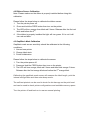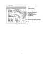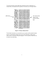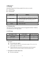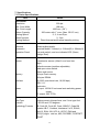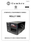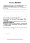
1
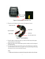
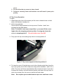
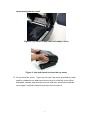
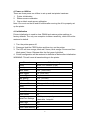
WPL305 Thermal Label Printer User’s Guide For Wasp Technologies DT/TT Printer Copyright Wasp Bar Code Technologies 2004. All rights reserved. No part of this publication may be reproduced or transmitted in any form or by any means without the written permission of Wasp Bar Code Technologies. The information contained in this document is subject to change without notice. Wasp is a trademark of Wasp Bar Code Technologies. All other trademarks are the property of their respective owners. i Contents 1. Introduction.........................................................................................1 2. Getting Started ....................................................................................1 2.1 Unpacking and Inspection............................................ 1 2.2 Equipment Checklist..................................................... 1 2.3 Printer Parts................................................................... 2 3. Setup....................................................................................................2 3.1 Setting Up the Printer ................................................... 2 3.2 Loading the Ribbon....................................................... 3 3.3 Loading Label Stock ..................................................... 4 3.7 Top Cover Operation..................................................... 6 4. Power on Utilities................................................................................8 4.1 Initialization ................................................................... 8 4.2 Ribbon Sensor Calibration ........................................... 9 4.3 Gap/Black Mark Calibration.......................................... 9 5. Maintenance ......................................................................................12 5.1 Cleaning ....................................................................... 12 6. Troubleshooting................................................................................12 6.1 LED Status ................................................................... 12 6.2 Print Quality ................................................................. 13 7. Specifications ...................................................................................14 7.1 Printer Specifications ................................................. 14 7.2 Label Stock Specifications......................................... 15 7.3 Ribbon Specifications................................................. 15 7.4. LED and Button Operation ........................................ 15 8. Product Support ...............................................................................16 9. Warranty Information........................................................................16 Revised Date: 7/26/2004 ii 1. Introduction Thank you for purchasing the W305 Thermal Transfer and Direct Thermal Bar Code Printer. Although the printer takes only a small amount of space, it delivers reliable, superior performance. This printer provides both thermal transfer and direct thermal printing at user selectable speed of: 2.0, 3.0, 4.0 or 5.0ips. It accepts roll feed, die-cut, and fan-fold labels for both thermal transfer and direct thermal printing. All common bar codes formats are available. Fonts and bar codes can be printed in 4 directions, 8 different alphanumeric bitmap fonts and a build-in true type font capability. You will enjoy high throughput for printing labels with this printer. 2. Getting Started 2.1 Unpacking and Inspection This printer has been specially packaged to withstand damage during shipping. Please carefully inspect the packaging and printer upon receipt. Please retain the packaging materials in case you need to reship the printer. 2.2 Equipment Checklist Printer Software CD disk Sample ribbon roll Sample label roll Label spindle (1 inch diameter core) 2 Label spindle fixed tabs with 1.5” core adapters Paper core 2 Ribbon supply/rewind spindles Parallel / Centronics cable Auto switching power supply Power cord Quick start guide To unpack the unit, remove the packaging material and parts carefully from the box. Remove and discard the tape holding the two halves of the printer and the media door. Open the media door and remove the Styrofoam. Open the printer and remove the two cushioning pads from the mouth of the printer. Remove the protective covers over the media door and back viewing door. 2.3 Printer Parts Ribbon Access Window LED Indicator Feed Button Printer Top Cover Top Cover Open Lever Figure 1: Top front view 3. Setup 3.1 Setting Up the Printer 1. Place the printer on a flat, secure surface. 2. Make sure the power switch is off. 3. Connect the printer to the computer with the Centronics or USB cable. 4. Plug the power cord into the power supply connector at the rear of the printer, and then plug the power cord into a properly grounded receptable. Rear Paper Guides Wall Plug USB Centronics / Parallel RS-23 Power Power Switch Figure 2: Back of Printer Parts 2 Power Supply 3.2 Loading the Ribbon The printer automatically detects if a ribbon is installed after power on and will switch to thermal transfer or direct thermal printing mode. If printer does not detect the ribbon, the motor that drives the ribbon rewind spindle will be turned off. In case the ribbon is installed but the printer does not detect the ribbon, please refer to the ribbon calibration procedure to calibrate the ribbon sensor. NOTE: If you are using direct thermal labels you should not load a ribbon. 1. Push down on the ribbon access window to unlock and open the cover. 2. Wasp Ribbons come with the cardboard rewind core already attached to the ribbon for ease of accurate installation. Arrange the ribbon and core as seen in the picture below so that the core is rolled out about 4 inches and the dull side of the printer ribbon is facing toward you. On Wasp Ribbons the Wasp logo should face you. Rewind Core Spindle Ribbon Core 3. Put the two spindles into the two cores from the right. Make sure the right side of the spindle is flush with the core after insertion. 4. Pull the cover access lever to open the printer 5. Hold the ribbon with the wide end of the spindle on the right and lower the rewind core through the back of the ribbon compartment Back Hub Ribbon Access Window Front Hub 3 6. 7. 8. 9. Figure 3: Ribbon installation Attach the ribbon spindle to the Back Hub by placing the left side of the spindle against the knob with the spring on it and compressing with the ribbon spindle. Slide the right side down over the other knob. The ribbon spindle should not be able to be removed without re-compressing the spring. You may have to turn the ribbon until the grooves on the spindle align and it clicks into place. Reach between the two halves of the printer and gently pull the rewind spindle and core under and around the print head and mount it on the Front Hub as above. Rotate the ribbon rewind core away from you until the black ribbon is on the rewind core. Close the ribbon access window and press down to lock it. Make sure both the ribbon access window and the printer top cover are closed when powering up the printer. 3.3 Loading Label Stock 1. Insert a 1” label spindle into the label roll. If your paper core is 1 inch, you can remove the 1.5” core adapters from the centering tab. If the label width is 4 inches wide, the two centering tabs are not required. 1.5” Core Adapter 1” Label Spindle Printing Side Centering Tab Face Up Figure 4: Label Roll Installation 2. Open the printer’s top cover by pulling the yellow top cover open levers located on each side of the printer and lifting the top cover. A top cover support at the rear of the printer will hold the printer top cover open. 4 Lower Cover Figure 5: Pull the lever to open the cover 3. Place the roll of labels onto the center of the paper roll mount. Printer Top Cover Support Bar Paper Roll Mount Teflon Bar Paper Guide Top Cover Open Lever Figure 6: Label installation 4. Feed the paper, printing side face up, under the Teflon bar and the paper guide and pass over the platen. 5. Adjust the yellow center-biased paper guides to slightly touch the edges of the label backing. 6. To close the printer top cover, lift the cover to the ultimate open angle then use both hands to close the cover gently. Close the printer top cover slowly and make sure the cover locks latch securely. Note: 1. Make sure hands are not placed in the printer when close the top 5 cover. 2. Do not allow the top cover to slam closed. 3. Failure to securely close and lock the cover will result in poor print quality. 3.7 Top Cover Operation To Open: 1. When facing the front of the printer pull the cover release levers on both sides of the printer towards you. 2. Lift the top gradually. There are two stop positions for the top cover. Position 1 and 2 are indicated on the label below. Note: To hold the cover open at position 1, you must lift the cover higher than the stopping point at position 1 and gently lower the cover to stopping point 1. Do not let the cover free fall! 3. Fully open the top cover and gently lower it to stop position 2. Figure 7: Top cover support is fixed at position 2 4. To close the cover, lift up the top cover to the ultimate angle then close the top cover gently and it will be kept at a stop position between 1 and 2 for a while. The cover will close automatically after several minutes. If you want to speed the closing, use both hands to gently push down the top cover to close it and make sure the cover is latched on both sides. Note: Do not place your hands between top cover and lower cover 6 when closing the top cover! Figure 8: Top cover is fully open and ready to close Figure 9: Use both hands to close the top cover 5. Do not force the cover! If you are not sure if top cover is locked at a stop position, please do not push top cover to close it or the top cover will be damaged. Instead, open the top cover as wide as it will go and close the cover again. Use both hands to push top cover to close it. 7 4. Power on Utilities There are three power-on utilities to set up and test printer hardware. 1. Printer initialization 2. Ribbon sensor calibration 3. Gap or black mark sensor calibration Note: You must run the #2 and #3 utilities after running the #1 to properly set up the printer. 4.1 Initialization Printer initialization is used to clear DRAM and restore printer settings to factory defaults. The only one exception is ribbon sensitivity, which will not be restored to default. 1. Turn the printer power off. 2. Press and hold the FEED button and then turn on the printer. 3. The LED will turn orange, blink red 5 times, blink orange 5 times and then blink green 5 times. Release after the first green light blink. 4. Printer configuration will be restored to defaults as below after initialization. WARNING: This will reset all saved settings in the printer. Parameter Default setting Speed W305, 127 mm/sec (5 ips) Density 7 Label Width 4.25” (108.0 mm) Label Height 2.5” (63.4 mm) Sensor Type Gap sensor Gap Setting 0.12” (3.0 mm) Print Direction 0 Reference Point 0,0 (upper left corner) Offset 0 Tear Mode On Peel off Mode Off Cutter Mode Off Serial Port Settings 9600 bps, none parity, 8 data bits, 1 stop bit Code Page 850 Country Code 001 Clear Flash Memory No 8 4.2 Ribbon Sensor Calibration Note: Please make sure the ribbon is properly installed before doing this calibration. Please follow the steps below to calibrate the ribbon sensor. 1. Turn the printer power off. 2. Press and hold the FEED button then turn on the printer. 3. The LED will turn orange then blink red 5 times. Release after the first red blink and before the 5rd. 4. If the ribbon is properly installed the light will turn green. If it is not it will turn red and blink. 4.3 Gap/Black Mark Calibration Gap/black mark sensor sensitivity should be calibrated at the following conditions: 1. A brand new printer 2. Change label stock 3. Printer initialization Please follow the steps below to calibrate the sensor. 1. Turn the printer power off. 2. Press and hold the FEED button then turn on the printer. 3. The LED will turn orange, blink red 5 times and then blink orange 5 times. Release after the first orange blink and before the 5th orange blink. Calibrating the gap/black mark sensor will measure the label length, print the internal configuration and then enter dump mode. The self-test printout can be used to check for dot damage on the print head and can be used to check printer configurations and available memory space. Turn the printer off and back on to resume normal printing. 9 Print head check pattern Firmware version Firmware checksum Printed mileage (meter) Serial port configuration Country code Print speed (inch/sec) Print darkness Label size (inch) Gap distance (inch) Gap/black mark sensor sensitivity Numbers of download files Total & available memory space Figure 10: Self-test printout 10 The printer will enter dump mode after printing the printer configuration. In dump mode, all characters will be printed in 2 columns as in the figure below. ASCII Data Hex decimal data related to left column of ASCII data Figure 11: Dump mode printout The left side characters are received from your system and the right side data are the corresponding hexadecimal values of the characters. Dump mode allows users to verify and debug the program. Turn the printer off and back on to resume normal printing. 11 5. Maintenance 5.1 Cleaning Use one or more of the following supplies that meets your needs: Cleaning pens Cleaning swabs Lint-free cloth Printer Part Method Printer Head Let the print head to cool for one minute. Use a cleaning pen to swab the print elements. Platen Roller Rotate the platen roller and wipe it thoroughly with 70% alcohol and a cleaning swab, or lint-free cloth. Exterior Wipe it with water-dampened cloth. Interior Brush or air blow. 6. Troubleshooting This section lists common problems and some suggested solutions. Problems are indicated by the LED light pattern. 6.1 LED Status LED Status / Color Printer Status Solution Number Off off 1 Solid Green on 2 Blinking Green Pause 3 Blinking Red Stopped 4 1. No power. Turn on the power switch. Check if the green LED is lit on the power supply. If it is not on, the power supply may be broken. Check both power connection from the power cord to the power supply and from the power supply to the printer power jack. 2. The printer is on and ready to use. No action necessary. 12 3. The printer is paused. Press the feed button to resume printing. 4. The printer is out of label or ribbon or the printer settings are not correct Out of label or ribbon Load a roll of labels and follow the instructions in Loading the Labels, then press the feed button to resume printing. Load a ribbon and follow the instructions in Loading the Ribbon then press the feed button to resume printing. Printer setting is not correct Initialize the printer by following the instructions in Power on Utilities. 6.2 Print Quality Continuous feeding labels The printer settings may be wrong. Please do the Initialization and Gap/Black Mark Calibration. No print on the label Is the label or ribbon loaded correctly? Follow the instructions in Loading the Labels or Loading the Ribbon. Has the ribbon run out? Follow the instructions in Loading the Ribbon. Poor print quality Top cover is not closed properly. Close the top cover completely and make sure the right side and left side levers are latched to the top cover properly. Clean the thermal print head. Adjust the print density setting. Ribbon and paper media are not compatible. 13 7. Specifications 7.1 Printer Specifications Item Mechanism Resolution Max. Print Width Max. Print Length Ribbon Capacity Printing Speed Peeler function Printing Method Enclosure Structure Dimension Operation Panel Hardware Sensor Memory Interface Power Firmware Font Type Rotation Symbology Formats W305 203 dpi. 108 mm. 1000 mm ( 39” ). 300 meter with 1” core. (Max. OD 67 mm) 2, 3, 4 and 5 ips. 2, 3 ips Direct thermal and thermal transfer printing. Double-walled plastic. Standard Model: 314mm(L) x 213mm(W) x 188mm(H) One push switch, and one indicator LED (Green, Orange, Red). Transmissive sensor (offset 6 mm from liner edge). Reflective sensor (position adjustable). Head open micro switch. Ribbon end sensor 1M byte Flash memory 2M bytes DRAM RS-232C (max baud rate, 19,200 bps). USB: V1.1. Centronics. AC input: 100-240V universal auto switching power supply. DC output: 24V 3.75A. 8 alpha-numeric bitmap fonts, and 1 true type font. 0, 90,180 and 270 degrees. 1D: Code 39, Code 93, Code 128UCC, Code128 subsets A.B.C, Codabar, Interleave 2 of 5, EAN-8, EAN-13, EAN-128, UPC-A, UPC-E, EAN and UPC2(5) digits add-on, MSI, PLESSEY, POSTNET, CPOST 14 Command Set 2D: PDF-417, Maxicode, and DataMatrix. WPL Environment Operation Temperature: 5 ~ 40 . Relative Humidity: 25% ~ 85% (Non Condensing). Storage Temperature: -40 ~ 60 . Relative Humidity: 10% ~ 90% (Non Condensing). 7.2 Label Stock Specifications Item Specification Type Label (Continuous , Die-cut , Fan-fold). Wound Type Outside wound. Width 20mm ~ 112mm (0.78” ~ 4.4”). Length 10mm ~ 1000mm (0.4” ~ 39”). 25.4mm ~ 1000mm (1” ~ 39”).(for peeler and cutter) Thickness 0.06mm ~ 0.19mm. (2.3~7.4 mil), max. 150g/m2 Roll Diameter 5”. Roll Core Diameter 25.4mm ~ 76.2mm (1” ~ 3”). Gap Height 2mm min. Black Mark Height 2mm min. Black Mark Width 8mm min. 7.3 Ribbon Specifications Item Specification Type Wax, Wax / Resin, Resin. Core Diameter 1". Width Max 110mm. Capacity 300m with 1" core. Wound Type Outside wound. Ribbon End Clear or silver end tape. 7.4. LED and Button Operation LEDColor Green Orange Red Description The power is on and the device is ready to use. The system is detecting the paper and ribbon status. Printing error, such as paper empty, ribbon empty, cover opened, etc. 15 8. Product Support If you experience any problems with your Wasp printer that you are unable to resolve, use our online support site to register then call for technical assistance at (214) 547-4100, Monday through Friday, 8:00 AM – 5:00 PM Central Standard Time. You must register to be eligible for technical support. Our web site is www.waspbarcode.com You may also contact us in writing at: Wasp Technologies 1400 10th Street Plano, TX 75074 (214) 547-4100 (214) 547-4101 Fax 9. Warranty Information Wasp printers are warranted against defects in workmanship and materials for a period of one year from the date of shipment, provided that the product remains unmodified and is operated under normal and proper conditions. Note: Print heads are warranted for 90 days against defect in workmanship. Print heads will be replaced during the 90 day period once it is determined that the print head is defective. This warranty is limited to repair or replacement at Wasp Technologies’ option, with reasonable promptness after being notified. These provisions do not prolong the original warranty term for any product which has been repaired or replaced by Wasp Technologies. This warranty applies to the original owner and does not extend to any product which has been subject to misuse, neglect, accidental damage, unauthorized repair, or tampering. No other express warranty is given. The replacement or repair of a product is your exclusive remedy. Any other implied warranty of merchantability or fitness is limited to the duration of this written warranty. Some states, provinces and countries do not allow how long an implied warranty lasts, so the above limitation may not apply to you. In no event shall Wasp Technologies be liable for consequential damages. Some states, provinces, and countries do not allow the exclusion or limitation of incidental or consequential damages, so the above may not apply to you. 16