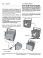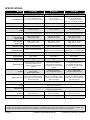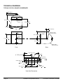
1
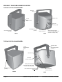
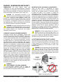
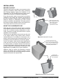
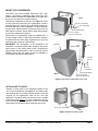
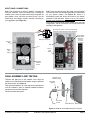
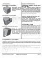
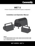
R-Series Installation and Operation Manual Models: R.15COAX, R.35COAX, R.35-3896 WEATHER-RESISTANT • R-SERIES IMPORTANT SAFETY INSTRUCTIONS RIGGING AND ELECTRICAL SAFETY Always follow these basic safety precautions when using or installing R-Series loudspeakers and accessories: DANGER: The loudspeakers described in this manual are designed and intended to be ‘flown’ or suspended using a variety of rigging hardware, means, and methods. Installation of loudspeakers should only be performed by trained and qualified personnel. It is strongly recommended that a licensed and certified professional structural engineer approve the mounting design. Severe injury and/or loss of life may occur if these products are improperly installed! All electrical connections must conform to applicable city, county, state, and national (NEC) electrical codes. •Read these instructions prior to assembly. •Keep these instructions for reference. •Heed all warnings. •Follow all instructions, particularly those pertaining to rigging, mounting, hanging and electrical connections. •Only use attachments and accessories that are specified and approved by the manufacturer. •Refer all servicing to qualified service personnel. Servicing is required when the apparatus has been damaged in any way, such as power-supply cord or plug is damaged, liquid has been spilled or objects have fallen into the apparatus, does not operate normally, or has been dropped. The terms caution, warning, and danger may be used in this manual to alert the reader to important safety considerations. If you have any questions or do not understand the meaning of these terms, do not proceed with installation. Contact your local dealer, distributor, or call Community directly for assistance. These terms are defined as: CAUTION: describes an operating condition or user action that may expose the equipment or user to potential damage or danger. DANGER: R-Series rigging fittings are rated at a Working Load Limit of 100 lbs (45.4 kg) with a 10:1 safety margin. No single rigging fitting should ever be subjected to a load that is greater than 100 lbs. Failure to heed this warning could result in injury or death! IMPORTANT: Refer to the sections on installation and connections later in this manual for additional information on rigging and electrical safety. DANGER: It is possible to experience severe electrical shock from a power amplifier. Always make sure that all power amplifiers are in the “OFF" position and unplugged from an AC Mains supply before performing electrical work. WARNING: describes an operating condition or user action that will likely cause damage to the equipment or injury to the user or to others in the vicinity. DANGER: describes an operating condition or user action that will immediately damage the equipment and/or be extremely dangerous or life threatening to the user or to others in the vicinity. These servicing instructions are for use by qualified service personnel only. To reduce the risk of fire or electric shock do not perform any servicing other than that contained in the operating instructions unless you are qualified to do so. CAUTION: Installation of R-Series loudspeakers should only be performed by trained and qualified personnel. It is strongly recommended that a licensed and certified professional structural engineer approve the mounting. Severe injury and/or loss of life may occur if this product is improperly installed. Page 2 Installation and Operation Manual R.15COAX, R.35COAX, R.35-3896 UNPACKING AND INSPECTION SYSTEM INFORMATION Community R-Series loudspeakers are engineered and manufactured to be rugged and they are carefully packed in sturdy cartons. Make sure that the number of cartons shown on the freight documents have actually been delivered. It is wise to thoroughly inspect each unit after it has been removed from the packaging, as damage could occur during shipping. PHYSICAL FEATURES / GENERAL DESCRIPTION Please note that once the shipment has left your dealer or the Community factory, the responsibility for damage is always borne by the freight company. If damage has occurred during shipping, you must file a claim directly with the freight company. It’s very important to contact the freight company as soon as possible after receiving your shipment, as most freight companies have a short time limit within which they will investigate claims. Be sure to save the carton and the packing material, as most claims will be denied if these materials are not retained. Your Community dealer and the factory will try to help in any way they can, but it is the responsibility of the party receiving the shipment to file the damage claim. It is always a good idea to retain the carton and packing materials indefinitely, if possible, in the event that the unit may need to be returned to your dealer or distributor for repair. The R.15COAX and R.35COAX are two-way, full-range loudspeaker systems, and the R.35-3896 is a three-way full-range loudspeaker. All of these models are designed to provide high quality voice and music reproduction in outdoor direct exposure applications in the harshest environments. They are designed to withstand long-term exposure to tough, environmental conditions, indoors or outdoors, and to provide many years of trouble-free service while maintaining their out-of-the-box performance and appearance. The modified trapezoidal shape emulates a traditional enclosure, and presents a compact modern look. The enclosures are constructed of UV-stabilized ABS plastic and designed with interior ribbing and other internal structural support for added rigidity. This reinforcement allows for improved low frequency performance as well as a stronger, less resonant enclosure. The R.35 models have additional weather-treated wooden inserts to reduce rear and lateral radiation. All models are available in a standard light grey, black or white matte paintable finish with options for custom colors that can be specially ordered. The steel mounting yoke and grille are color matched to the cabinet for all models. Hardware required to mount the yoke to the installation surface must be customer supplied. IN THE CARTON Each shipping carton contains the following items: •One (1) R-Series Loudspeaker The smaller R-Series loudspeakers offer numerous features and technologies that provide unprecedented sonic quality and installation flexibility. Some of these include: •One (1) Steel Mounting Yoke •One (1) Weather Cover and Gasket •Weather Cover Mounting Hardware: Pan Head Screws [R.15: 3.5 x 13mm (x4); R.35: 3.5 x 19mm (x6)] •One (1) 13.5mm (.5") ID Gland Nut •One (1) Operation and Installation Manual •One (1) Warranty Card •Yoke Mounting Hardware: 8x32 mm threaded studs (x2), 8mm lock washers (x2), 8mm flat washers (x2), 8mm hex nuts (x2),and 2" OD rubber gaskets (x2), All 8 mm hardware is stainless steel. DANGER: It is essential that a safety cable (not supplied) be utilized whenever an R-Series Loudspeaker is installed. The safety cable must be secured to a suitable load-bearing point separate from the loudspeaker mounting point, with as little slack as possible so as not to develop undue kinetic force if the mounting bracket (yoke) were to fail. The safety cable should be attached to the integrated SS loop on the rear of the cabinet. Refer to the Product Features images on the next page. R.15COAX, R.35COAX, R.35-3896 R.15 AND R.35 FEATURES / TECHNOLOGY •Unique full-range compact high output loudspeakers with advanced passive crossover technology •All models are weather-resistant, suitable for outdoor direct exposure •All-weather ABS plastic UV stabilized reinforced enclosure •Protective steel grilles and mounting yokes are covered with a rugged, zinc-rich epoxy dual-layer powder-coat finish for superior resistance to weather •Stainless steel hardware •All models are available in light grey, black or white; custom colors are also available •Includes built-in autoformer for 70V / 100V applications Installation and Operation Manual Page 3 PRODUCT FEATURES IDENTIFICATION TYPICAL R.15 FULL-RANGE MODEL Bracket / Yoke Weather Cover 3-Layer WeatherStop™ Grille Gland Nut 13.5mm (.5") ID 8mm Rigging Points (2 sides) 8mm Rigging Points (2 sides) FRONT 3.5 x 13mm Pan Head Screws (x4) Safety Attachment Point (user must supply appropriate fastener and safety cable) REAR TYPICAL R.35 FULL-RANGE MODEL Bracket / Yoke 3-Layer WeatherStop™ Grille 8mm Rigging Points (2 sides) Weather Cover Gland Nut 13.5mm (.5") ID Safety Attachment Point (user must supply appropriate fastener and safety cable) 8mm Rigging Points (2 sides) Internal Transformer Mounting Bolts (Do not adjust) FRONT Page 4 3.5 x 19mm Pan Head Screws (x6) REAR Installation and Operation Manual R.15COAX, R.35COAX, R.35-3896 RIGGING / SUSPENSION AND SAFETY TERMINOLOGY: The terms “rigging", “flying" and “suspension" are often used interchangeably to describe the installation of loudspeaker systems above ground level. None of these terms pertain to, or attempt to describe, the actual method that is used (cables, yokes, chains, etc.). DANGER: The loudspeakers described in this manual are designed and intended to be suspended using a variety of rigging hardware, means, and methods. It is essential that all installation work involving the suspension of these loudspeaker products be performed by competent, knowledgeable persons who understand safe rigging practices. Severe injury and/or loss of life may occur if these products are improperly suspended. DANGER: All rigging fittings and inserts must remain sealed with the included hardware or they must be fitted with properly rated optional mounting hardware. Any missing fasteners will compromise the weather resistance of the enclosure. COMMUNITY RIGGING HARDWARE WARRANTY: Community warrants that its loudspeaker systems and its optional mounting and rigging hardware have been carefully designed and tested. Community loudspeakers may be safely suspended when each loudspeaker model is suspended with Community-manufactured mounting and rigging brackets or yokes specifically designed for use with that particular model of loudspeaker. This warranty applies only for use under normal environmental conditions, and when all loudspeakers, component parts, yokes and hardware are assembled and installed in strict accordance with Community’s installation guidelines contained herein. Beyond this, Community assumes no further or extended responsibility or liability, in any way or by any means whatsoever. It is the responsibility of the installer to insure that safe installation practices are followed, and that such practices are in accordance with any and all local, state, federal, or other, codes, conditions, and regulations that may apply to, or govern the practice of, rigging, mounting, and construction work in the relevant geographic territory. Any modifications made to any parts or materials manufactured or supplied by Community shall immediately void all pledges of warranty or surety, related in any way to the safe use of those parts and materials. IMPORTANT NOTES ON RIGGING LOUDSPEAKERS There are three areas of responsibility for rigging loudspeakers. The first is the building structure. Always consult with the building architect or structural engineer to assure the ability of the structure to support the loudspeaker system. The second area of responsibility is the loudspeaker itself. Community certifies its loudspeaker systems and rigging accessories for suspension when they are properly installed according to our published guidelines. The third area of responsibility is everything between the loudspeaker and the building structure and the actual process of installation. The installing contractor assumes this responsibility. Loudspeaker rigging should be performed only by certified rigging professionals using certified rigging hardware chosen for the specific application. Prior to installation, the contractor should present a rigging plan, with drawing and detailed parts list, to a licensed structural engineer (P.E.) or architect for written approval. WARNING: R-Series rigging fittings are rated at a Working Load Limit of 100 lbs (45.4kg) with a 10:1 safety margin. No single rigging fitting should ever be subjected to a load that is greater than 100 lbs. Failure to heed this warning could result in injury or death! ACCEPTABLE MOUNTING POINT LOADING The mounting points should always be used so that either shear force is applied perpendicular to the direction of and in tight proximity to the mounting hole, or tension force is applied perpendicular to the enclosure surface. See Figure 1 below. DANGER: Use the mounting points only as described above. Do not use them in such a way as to apply sideways leverage to them. Failure to follow this instruction could result in immediate failure of the mounting points resulting in damage to the loudspeaker and serious injury or death to personnel. Correct NOT Correct Yoke tight against rubber washer and enclosure WARNING NON-COMMUNITY RIGGING HARDWARE: Non-Community hardware used for rigging an R-Series loudspeaker must be certified by the supplier for such use and must be properly rated for safety. Bracket spaced away from enclosure Yoke Custom Bracket Enclosure Figure 1. Mounting point load R.15COAX, R.35COAX, R.35-3896 Installation and Operation Manual Page 5 INSTALLATION BEFORE YOU START q Read all instructions and gather tools necessary before starting the installation. Please read all safety instructions and warnings regarding rigging and installation of the loudspeaker. The "q" preceding each step can be used to check off each step as it is completed (or applicable). Every effort has been made to ensure that the information contained in this manual was complete and accurate at the time of printing. However, due to ongoing technical advances, changes or modifications may have occurred that are not covered in this publication. The latest version of this manual is always available at www.communitypro.com. The revision date can be found on the rear cover. R.15 Yoke Mount using holes in the yoke. Large hole in center notes center of gravity when loudspeaker is suspended from above. MOUNT THE LOUDSPEAKER YOKE Attach the yoke to the support structure prior to mounting the loudspeaker enclosure. Community offers several pole mount kits to facilitate mounting loudspeakers to poles. Follow instructions included with those items for proper installation of the loudspeaker. q Determine the appropriate location and mount the yoke to the support structure using properly rated, corrosionresistant fasteners. For mounting to a round pole, use a properly rated mounting system. Mounting hardware is not included and should be specified by a structural engineer. Figure 2a. Orient the R.15 yoke Use holes aligned with large center hole as primary mounting points - these are aligned with the center of gravity. Use other holes as secondary reinforcement. For the R.35 models, ensure that the wider angled portion of the yoke will be at the rear of the loudspeaker when in the vertical position, or toward the bottom of the enclosure in the horizontal position. Always use the holes in line with the larger center hole as the primary mounting points. See Figures 2a (R.15) and 2b (R.35) for yoke orientations. Additional yokes for pan/tilt and down-firing mounting options are available (see Accessories section). Custom brackets may be used, but must be approved by a structural engineer and rated for the expected load. R.35 Yoke Orient angled side to the rear of the loudspeaker Figure 2b. Orient the R.35 yoke correctly Page 6 Installation and Operation Manual R.15COAX, R.35COAX, R.35-3896 MOUNT THE LOUDSPEAKER The factory yoke uses threaded studs and a nut / lock washer / flat washer combination rather than bolts. This makes it easier to attach the loudspeaker to the yoke after the yoke is mounted to the support structure. q Attach the loudspeaker to the yoke. See Figure 3. Screw an 8mm stud into each side of the loudspeaker so that it protrudes about 3/4" (19mm). Place the rubber washers on the studs and then lift the loudspeaker into place between the yoke arms. Attach as shown. Support the enclosure until both sides are secured. Tighten bolts to finger tight (enough to hold the loudspeaker in position). 2" OD Rubber Gasket Yoke R.15 8mm SS Lock Washer 8mm SS Hex Nut 8mm SS Flat Washer q Determine the approximate angle of downward tilt. It must be angled at least 5° down from horizontal to maintain the stated enclosure IP55 rating. Tighten the hex nuts until sufficiently tight enough to hold the angle. Enclosure IMPORTANT: The loudspeaker is not designed to be rotated 90° or mounted upside-down. Doing so may cause water pooling in the safety cable recess, compromising rigging safety and performance, and may void the product warranty. Pan-tilt and full rotation yokes are available for multi-angled and down-fire applications. Enclosure 8 x 32 mm SS Stud (leave 3/4" sticking out) 2" OD Rubber Gasket Yoke 8mm SS Hex Nut 8mm SS Lock Washer 8mm SS Flat Washer R.35 8 x 32 mm SS Stud (leave 3/4" sticking out) Figure 3. Mount the loudspeaker to the yoke ATTACH SAFETY CABLE q Attach a safety cable to the integrated eyebolt on the rear of each loudspeaker (see Figure 4). The safety cable and hardware are not included. Please consult a structural engineer for the appropriate cable for the load and application. The safety cable must be secured to a suitable load-bearing point separate from the loudspeaker mounting point, with as little slack as possible, so as not to develop undue kinetic force if the R-Series mounting were to fail. R.15 Attach safety cable here R.35 Figure 4. Attach the safety cable R.15COAX, R.35COAX, R.35-3896 Installation and Operation Manual Page 7 WIRING AND ELECTRICAL SAFETY All standard R.15 and R.35 loudspeakers are provided with two methods of connecting the amplifier to the loudspeaker: a standard NL4-type locking connector, and a pressurescrew terminal strip. The loudspeaker is intended to be connected directly to the amplifier. If installed outdoors, the insulation of the installerprovided cabling should be resistant to water, the effects of temperature, and the effects of ultraviolet radiation from the sun. We recommend the use of a SJOW or SJOOW rated cable for most applications. To make the connection from the loudspeaker to the wiring junction box when less than 3m (10') in length. These are recommended insulations: UV-stabilized polyethylene, neoprene, Teflon™, Silicon™, and Hypalon™. The following insulations are not recommended because of potentially shorter life expectancy in outdoor environments: rubber, PVC (polyvinyl chloride), polypropylene, polyurethane, and nylon. UV-stabilized polypropylene may be acceptable. Using the recommended cable with the included gland nut and the weather cover will form a good weather-tight seal. Examples of recommended cable include: Grainger #1W312 (www.grainger.com) McMaster-Carr #7422K61 (www.mcmaster.com) q Wire the loudspeaker. We recommend using forked terminals with barrel-type crimp connectors that are crimped with a forged crimp tool (such as Klein 1005) or a ratcheting tool (such as Klein T1720), as this method, when properly executed, results in a gas-tight connection that is quick and easy to accomplish. Important Note: If the NL4 connection is used then the weatherproof cover cannot be attached. Direct connection to the terminal strips is the preferred connection method for all permanent or outdoor applications. Page 8 (–) ( Black) (+) ( White) Standard Wiring IMPORTANT: The gland nut, weather cover and all of the attachment screws must be used in outdoor and indoor harsh environment applications. Without these, the loudspeaker will not have the stated weatherresistant rating and may negate the warranty. IMPORTANT: All electrical installation connections for loudspeaker lines are subject to all applicable governmental building and fire codes. The selection of appropriate electrical hardware to interface with the R-Series loudspeaker lies solely with the installation professional. Community recommends that an appropriately licensed engineer, electrician, or other qualified professional identify and select the appropriate conduit, fittings, wire, etc. for the installation. DANGER: The output power capabilities of audio amplifiers present a danger to installers especially in 70-volt and 100-volt distributed systems. To minimize the risk of electric shock from loudspeaker connecting cables, confirm that the power amplifiers are turned “off" before connecting loudspeaker cable(s) to the loudspeaker or amplifier. Always follow local electrical codes and proper electrical safety procedures. Installation and Operation Manual R.15COAX, R.35COAX, R.35-3896 INPUT PANEL CONNECTIONS R.15: The connectors are wired in parallel. If utilizing the NL4-type connector, refer to the detail inset. If utilizing the weather cover, insert the cable end through the gland nut and weather cover, and wire the terminal strip. Set the Music/Voice and Voltage selector switches according to your application (see Figure 5a). + from Amplifier R.35: Insert the cable through the gland nut and weather cover and wire the unit referencing the label for connections for your system voltage. See Figure 5b. There is a preinstalled jumper that should be moved to the bottom terminals for 8Ω operation. Failure to do so can result in damage to the loudspeaker and/or amplifier. Set the Music/ Voice switch to the desired position based upon your type of application. The NL4 connection can only be used for low impedance 8Ω operation. 1+ Must remove jumper, or move it to the bottom terminals, for 8Ω operation (see arrow below) 1– – 2– Terminal Strip Follow label to determine correct (+) terminal connection 2+ NL4-Type Connector Terminal Strip NL4 NL4 Music / Voice Switch Music/ Voice Switch Wattage Selector Switch Figure 5a. R.15 input panel Figure 5b. R.35 input panel FINAL ASSEMBLY AND TESTING Secure the gland nut to the weather cover. Align the weather cover with the holes and attach using the provided pan head screws. See Figure 6. Weather Cover, Gasket (internal) Gland Nut (Barrel) All provided hardware (or other approved replacement) must be installed in order to maintain weather-resistance and preserve the product warranty. Power and test the system. Wire Pan Head Screws Gland Nut (Nut) Input panel Figure 6. Weather cover attachment (R.15 shown) R.15COAX, R.35COAX, R.35-3896 Installation and Operation Manual Page 9 FIELD SERVICE Any driver or crossover service required is accessed from the front of the enclosure by first removing the front grille and then unscrewing and removing the LF driver or the horn assembly. Take note of wiring positions prior to removing any drivers from the loudspeaker. In order to maintain the weather resistance, components and assemblies must not remain removed from the loudspeaker any longer than needed for replacement. Exposure of internal components to the elements for extended periods could cause failures and void the warranty on the loudspeaker. Remove the grille. Refer to illustrations in Figure 7. The grille frame locks into the enclosure frame. Carefully insert a thin flat bladed screwdriver between the grille frame and the enclosure frame while gently pressing down on the grille. Starting at the top and moving down, twist the blade to pop the grille frame free of the enclosure. There is a safety tether at the bottom of the grille that can be unhooked to fully remove the grille. CUSTOMER SUPPORT INFORMATION AND APPLICATION ASSISTANCE For more information on installing and operating your R-Series loudspeaker, please refer to Community’s web site at www.communitypro.com. For application support, service or warranty information, refer to Community’s web site or contact Community's TAG Team (Technical Applications Group) for additional assistance at 610-876-3400 or tollfree (US and Canada) at 800-523-4934. To obtain specific warranty information and available service locations for countries other than the United States of America, contact the authorized Community Distributor for your specific country or region. Remove the screws holding the LF driver in the face and replace or service the components as necessary. Replace the driver securing it with all of the original hardware. Reattach the grille safety tether to the face and push the grille frame into place - one side and then the other, ensuring that the frames are fully seated. The grille should easily snap into place. Unhook grille tether to fully remove grille Insert thin blade of screwdriver between frame and enclosure and move down seam while twisting to pop grille loose Page 10 Figure 7. Remove grille (R.15 shown) Installation and Operation Manual R.15COAX, R.35COAX, R.35-3896 MAINTAINING WEATHER RESISTANCE GUIDELINES FOR R-SERIES OUTDOOR USE R-Series is suitable for outdoor installation when used as recommended. For best results in outdoor applications, follow these guidelines: •Always orient the loudspeaker so the mouth of the horn is, at a minimum, pointing at least 5 degrees downward. Failure to do this could result in water collecting inside the enclosure under extreme weather conditions. •When handling an R-Series loudspeaker, be careful not to scratch or scrape the finish on the grille, yoke, or enclosure. •All mounting holes must be sealed off with the stainless steel bolts, washers, and rubber washers supplied. If, for any reason, these bolts must be removed, seal off the hole with silicone caulking or some other suitable weather-tight sealant. •The rubber washers supplied with the mounting bolts must always seat against the enclosure. •The grille assembly is designed to prevent normal and wind-driven rain from directly entering the mouth of the loudspeaker. The grille is not designed to withstand such things as being directly sprayed from a hose; therefore this should be avoided. •If you use any hardware in place of hardware provided with your R-Series loudspeaker, it should also be made of stainless steel. NOTES: R.15COAX, R.35COAX, R.35-3896 Installation and Operation Manual Page 11 SPECIFICATIONS MODEL Loudspeaker Type R.15COAX R.35COAX R.35-3896 2 way, full range, coaxial 2 way, full range, coaxial 3 way, full range, triaxial LF: 1 x 10" cone, HF: 1 x 1.25" exit compression driver LF: 1 x 8" cone, MR: 2 x 2.35" MultiSource Waveguide compression HF: 1 x 1" exit compression driver LF: 1 x 6.5" carbon ring cone, Driver Complement HF: 1 x 1.25" exit compression driver Coverage Pattern (H x V) 100° x 100° 90° x 90° 90° x 60° Operating Range (-10 dB) 90 Hz - 16 kHz 70 Hz - 16 kHz 80 Hz - 16 kHz 125 Hz - 12.5 kHz 110 Hz - 12.5 kHz 120 Hz to 12.5 kHz 150W RMS,300W Program, 35 volts RMS, 69 volts momentary peak 200W RMS, 400W Program, 40 volts RMS, 80 volts momentary peak 400W RMS, 800W Program, 56 volts RMS, 113 volts momentary peak 94dB (125 Hz–10 kHz) 92dB (250 Hz-4 kHz) 97dB (125 Hz–10 kHz) 97dB (250 Hz–4 kHz) 98dB (125 Hz–10 kHz) 97dB (250 Hz–4 kHz) 95dB (125 Hz–10 kHz) 93dB (250 Hz-4 kHz) 99dB (125 Hz–10 kHz) 99dB (250 Hz–4 kHz) 100dB (125 Hz–10 kHz) 99dB (250 Hz–4 kHz) Maximum SPL Continuous / Peak Music 116dB (122dB peak) Speech 117dB (123dB peak) Music 120dB (126dB peak) Speech 122dB (128dB peak) Music 124dB (130dB peak) Speech 126dB (132dB peak) Nominal, Minimal Impedance 8 Ohms, 4.2 Ohms @ 12.5 kHz Music 8 Ohms, 5.9 Ohms @ 200 Hz Speech 8 Ohms, 5.5 Ohms @ 5 kHz Music 8 Ohms, 6 Ohms @ 9 kHz Speech 8 Ohms, 4.1 Ohms @ 8 kHz 1.3 kHz 1.3 kHz 850 Hz, 2.7 kHz 90Hz 24dB/oct 70Hz 24dB/oct 80Hz 24dB/oct n/a n/a No NL4 Speakon-type connector and 2-position terminal strip for low impedance or constant voltage operation NL4 Speakon-type connector for low impedance operation only; and 7-position terminal strip for low impedance or constant voltage operation NL4 Speakon-type connector for low impedance operation only; and 7-position terminal strip for low impedance or constant voltage operation Controls 5-position wattage / low impedance selector switch Music / speech switch Music / speech switch, 70V/ 100V operation jumper Music / speech switch, 70V/ 100V operation jumper Rigging Provisions Two 8mm rigging points, Zinc-rich epoxy dual-layer powdercoated yoke, Included integral safety cable mounting point Two 8mm rigging points, Zinc-rich epoxy dual-layer powdercoated yoke, Included integral safety cable mounting point Two 8mm rigging points, Zinc-rich epoxy dual-layer powdercoated yoke, Included integral safety cable mounting point Frequency Response (-3 dB) Input Ratings Music Sensitivity 1W/1m (free space SPL) Speech range Voice Sensitivity 1W/1m (free space SPL) Speech range Crossover Frequency Recommended High Pass Filter: Horn Rotatable Input Connection Construction ABS plastic, matte finish, paintable Light Grey, Black or White (standard) RAL # 7038, 9004 or 9003 Finish IP55W per IEC 529 at 5° down-tilt Designed to MIL-STD-810G Environmental Dimensions HxWxD Net Weight with yoke 9" x 10.2" x 10.2" (229 x 259 x 259 mm) 11" x 13" x 13.5" (279 x 330 x 343 mm) 11" x 13" x 13.5" (279 x 330 x 343 mm) 17 lbs (7.7 kg) 26 lbs (11.8 kg) 34 lbs (15.4 kg) Community strives to improve its products on a continual basis. Specifications are therefore subject to change without notice. Note: Every effort has been made to insure that the information contained in this manual was complete and accurate at the time of printing. However, due to ongoing technical advances, changes or modifications may have occurred that are not covered in this manual. Visit Community at http://www.communitypro.com for the latest version of this manual and the most recent product information. Page 12 Installation and Operation Manual R.15COAX, R.35COAX, R.35-3896 TECHNICAL DRAWINGS TYPICAL R.15 FULL-RANGE LOUDSPEAKER 0.83" (21 mm) Center of Gravity 10.2" (259 mm) 4.83" (123 mm) 0.6" (15 mm) 10.15" (258 mm) 2" (51 mm) Top Center Line M8 Hang Point / Center of Gravity 7.08" (180 mm) Center of Gravity 9.03" (230 mm) 4.52" (115 mm) Safety Cable Attachment Point Front Sides 10.38" (263.7 mm) 5.2" (131.8 mm) Ø 0.51" (Ø 13 mm) Ø 0.35" (Ø 9 mm) Ø 0.35" (Ø 9 mm) 2.6" (66 mm) 2.6" (66 mm) Yoke Hole Dimensions R.15COAX, R.35COAX, R.35-3896 Installation and Operation Manual Page 13 TECHNICAL DRAWINGS TYPICAL R.35 FULL-RANGE LOUDSPEAKER 0.84" (21mm) 13.5" (343mm) 1" (25mm) Center of Gravity 8.22" (209mm) 13" (330mm) Top 3.17" (81mm) Center Line M8 Hang Point / Center of Gravity 8.54" (217mm) 11" (279mm) Center of Gravity 5.5" (140mm) Safety Cable Attachment Point Front Sides 12.12" (307.7 mm) Ø 0.51" (Ø 13 mm) 6.06" (153.9 mm) 1.58" (40 mm) 0.98" (25 mm) Ø 0.35" (Ø 9 mm) 8 places 2.6" (66 mm) 2.6" (66 mm) 4.65" (118.1 mm) 4.65" (118.1 mm) Yoke Hole Dimensions Page 14 Installation and Operation Manual R.15COAX, R.35COAX, R.35-3896 ACCESSORIES WARRANTY INFORMATION R-VTY15 VARY-TILT YOKE FOR R.15 TRANSFERABLE WARRANTY “(LIMITED)" VALID IN THE USA ONLY Provides pan-tilt operation. Zinc-rich epoxy dual-layer powder-coated steel with hardware, color-matched to loudspeaker. R-VTY35 VARY-TILT YOKE FOR R.35 Provides pan-tilt operation. Zinc-rich epoxy dual-layer powder-coated steel with hardware, color-matched to loudspeaker. The R-Series Loudspeaker Systems are designed and backed by Community Professional Loudspeakers. For complete warranty information within the USA please refer to the Warranty Card enclosed with the product. Please call 610-876-3400 to locate your nearest Authorized Field Service Station. For Factory Service call 610-876-3400. You must obtain a Return Authorization (R/A) number prior to the return of your product for factory service. WARRANTY INFORMATION AND SERVICE FOR COUNTRIES OTHER THAN THE USA To obtain specific warranty information and available service locations for countries other than the United States of America, contact the authorized Community Distributor for your specific country or region. SHIPPING DAMAGE / CLAIMS R-FRY35 FULL ROTATION YOKE FOR R.35 Provides full rotation mounting capability for downfiring application (i.e. top of press box). Zinc-rich epoxy dual-layer powder-coated steel with hardware, colormatched to loudspeaker. If the product is damaged during transit you must file a damage claim directly with the freight company. It’s very important to contact the freight company as soon as possible after receiving your shipment, as most freight companies have a short time limit within which they will investigate claims. Be sure to save the carton and packing materials, as damage claims can be denied if these materials are not retained. If evidence of physical damage exists upon arrival, be cautious before signing the delivery acceptance receipt. Often, the fine print will waive your right to file a claim for damage or loss after you sign it. Make sure that the number of cartons shown on the freight documents have actually been delivered. EC STATEMENT OF CONFORMITY This document confirms that the range of products of Community Professional Loudspeakers bearing the CE label meets all of the requirements in the EMC directive 89/336/EEC laid down by the Member States Council for adjustment of legal requirements. Furthermore, the products comply with the rules and regulations referring to the electromagnetic compatibility of devices from 30-August-1995. The Community Professional Loudspeaker products bearing the CE label comply with the following harmonized or national standards: DIN EN 55013:08-1991, DIN EN 55020:05-1995, and DIN EN 55082-1:03-1993. The authorized declaration and compatibility certification resides with the manufacturer and can be viewed upon request. The responsible manufacturer is the company: Community Light & Sound 333 East Fifth Street, Chester, PA 19013 USA Phone: (610) 876-3400 • Fax: (610) 874-0190 Chester, PA USA June 2013 R.15COAX, R.35COAX, R.35-3896 Installation and Operation Manual Page 15 R-Series ©2013 Community Professional Loudspeakers Community Professional Loudspeakers 333 East Fifth Street, Chester, PA 19013-4511 USA Phone: (610) 876-3400 • Fax: (610) 874-0190 www.communitypro.com v: 27AUG2013