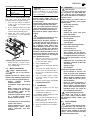
1
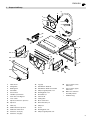
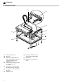
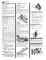
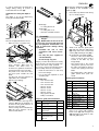
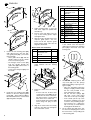
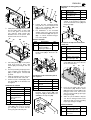
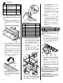
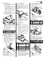
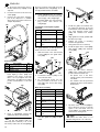
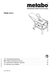
A0250IVZ.fm
TKHS 315 (AUS)
115 168 4633 / 1402 - 1.0
Operating Instruction . . . . . . . . . . . . . . . . . 3
U2a0250.fm
2
XA0034AUS1.fm
Operating Instruction
ENGLISH
ENGLISH
1. Scope of delivery
5
4
3
2
6
1
7
8
9
32
31
10
30
11
12
29
14
21
13
22
28
27
15
16
23
20
26
17
19
18
24
25
1
Table insert
16
Leg (4x)
2
Riving knife
17
Handwheel / blade tilt
3
Blade guard
18
Handwheel / blade rise and fall
4
Saw blade
19
Chipcase guide panel, front
5
Suction hose
20
Bearing plate, front
6
Handle for push block
21
Threaded rod
7
Push stick / feeding aid
22
Pinion shaft
8
Hose carrier
23
Setting tube
9
Rip fence extrusion / rip fence
24
Motor carrier unit
10
Rip fence
25
Dust extraction port
11
Table top
26
Chipcase
12
Guide extrusion / rip fence
27
Cover
13
Guide bar / mitre fence
28
Bearing plate, rear
14
Stanchion, short (2x)
29
Chipcase guide panel, rear
15
Stanchion, long (2x)
30
Fence carrier, lower /
mitre fence
31
Fence carrier, upper /
mitre fence
32
Mitre fence extrusion
–
Assembly wrench
–
Hardware bag
3
ENGLISH
2. Machine overview
33
34
35
36
42
37
38
39
41
40
4
33
Saw blade ∅315 mm
34
Rip fence
35
Table top of galvanized steel
plate – high stability under load
and permanent protection
against corrosion
36
Handwheel for setting the depth
of cut steplessly from
0 – 85 mm
37
Handwheel for stepless blade
tilt setting from 90° through 45°
38
Lock lever for locking the blade
tilt angle
39
ON/OFF switch
40
Stand with multiple reinforcement beads for high stability
41
Mitre fence
42
Maintenance-free induction
motor
ENGLISH
Table of Contents
4. Safety instructions
1.
Scope of delivery ........................ 3
4.1
2.
Machine overview ....................... 4
3.
Please read first!......................... 5
4.
Safety instructions ..................... 5
4.1 Specified conditions of use ........... 5
4.2 General safety instructions ........... 5
4.3 Symbols used throughout
these instructions.......................... 6
4.4 Safety devices .............................. 6
5.
Special product features............ 6
6.
Operating elements .................... 6
7.
Assembly..................................... 7
7.1 Mains connection........................ 13
7.2 Installation................................... 13
8.
Operation................................... 13
8.1 Dust collector .............................. 13
Specified conditions of
use
This machine is intended to rip and
crosscut grown timber, faced boards,
chip board and wood-core plywood
sheets, and similar wood-derived materials.
Do not cut round stock without suitable
jigs or fixtures. The rotating saw blade
could turn the workpiece.
Any other use is considered to be not as
specified and not permitted. The manufacturer is not liable for any damage
caused by unspecified use.
Modification of the machine or use of
parts not approved by the equipment
manufacturer can cause unforeseeable
damage!
8.2 Setting the depth of cut............... 14
4.2
8.3 Setting the saw blade tilt............. 14
When using this tool observe the following safety instructions, to exclude the
risk of personal injury or material damage.
Please also observe the special safety
instructions in the respective chapters;
where applicable, follow the legal directives or regulations for the prevention of
accidents pertaining to the use of circular saws.
8.4 Sawing with the rip fence............ 14
8.5 Sawing with the mitre fence........ 15
9.
Tips and tricks .......................... 15
10. Care and maintenance ............. 15
10.1 Saw blade change ...................... 15
10.2 Cleaning the saw blade's
height adjustment mechanism .... 15
10.3 Saw storage................................ 16
10.4 Maintenance ............................... 16
11. Repairs....................................... 16
12. Transportation .......................... 16
13. Available accessories ......... 16/19
14. Technical specifications .......... 17
3. Please read first!
•
Assemble tool in strict accordance
with these instructions. Only if you
follow the instructions exactly does
the machine conform to the safety
regulations and can be safely operated.
•
Read the safety instructions before
initial operation.
•
If you notice transport damage while
unpacking, notify your supplier
immediately. In this case, do not
assemble and operate the saw!
•
Dispose of the packing in an environmentally friendly manner. Take
to a proper collecting point.
•
Keep these instructions for reference on any issues you may be
uncertain about.
•
If you lend or sell this machine be
sure to have these instructions go
with it.
General safety instructions
A General hazards!
Keep your work area tidy – a messy
work area invites accidents.
Be alert. Know what you are doing. Set
out to work with reason. Do not operate
tool while under the influence of drugs,
alcohol or medication.
Consider environmental effects:
provide proper lighting.
Prevent adverse body positions. Ensure
firm footing and keep your balance at all
times. Use suitable workpiece supports
when cutting long stock.
Do not operate tool near inflammable liquids or gases.
The saw shall only be started and operated by persons familiar with circular
saws, and who are at any time aware of
the dangers associated with the operation of such tool.
Keep bystanders, particularly children,
out of the danger zone. Persons under
18 years of age shall use this tool only in
the course of their vocational training,
under the supervision of an instructor.
Do not permit other persons to touch the
tool or power cable while it is running.
Do not overload tool – use it only within
the performance range it was designed
for (see "Technical specifications").
B Danger! Risk of electric shock!
ronment.
Prevent body contact with earthed
objects such as radiators, pipes, cooking
stoves, refrigerators when operating this
tool.
Do not use the power cable for purposes
it is not intended for.
of personal injury and
A Risk
crushing by moving parts!
Do not operate the tool without installed
guards.
Always keep sufficient distance to the
saw blade. Use suitable feeding aids, if
necessary.
Keep sufficient distance to driven components when operating the electric tool.
Do not attempt to stop the saw blade by
pushing the workpiece against its side.
Ensure the tool is disconnected from
power supply before servicing.
Ensure that when switching on (e.g. after
servicing) no tools or loose parts are left
on or in the tool.
Turn power off if the tool is not used.
hazard, even with the
A Cutting
cutting tool at standstill!
Wear gloves when changing cutting
tools.
A
Risk of kickback (workpiece is
caught by the saw blade and thrown
against the operator):
Always work with a properly set riving
knife.
Do not jam workpieces.
Cut thin or thin-walled workpieces only
with fine-toothed saw blades. Always
use sharp saw blades.
If in doubt, check workpiece for inclusion
of foreign matter (e.g. nails or screws).
Cut only stock of dimensions that allow
for safe and secure holding while cutting.
Never cut several workpieces at the
same time – and also no bundles containing several individual pieces. Risk of
personal injury if individual pieces are
caught by the saw blade uncontrolled.
When cutting round stock, use a suitable
jig to prevent the workpiece from turning.
c
Drawing-in/trapping hazard!
Ensure that no parts of the body or clothing can be caught and drawn in by rotating components (no neckties, no loosefitting clothes; contain long hair with hairnet).
Never cut workpieces containing the following materials:
−
ropes
−
strings
−
cords
−
cables
−
wires
Do not expose tool to rain.
Do not operate tool in damp or wet envi-
5
ENGLISH
generated by insuffiA Hazard
cient personal protection gear!
Wear hearing protection.
Wear safety glasses.
Wear dust mask.
Wear suitable work clothes. When working outdoors wearing of non-slip shoes is
recommended.
of injury by inhaling wood
A Risk
dust!
Dust of certain timber species (e.g. oak,
beech, ash) can cause cancer when
inhaled: work only with a suitable dust
collector attached to the saw.
A Hazard generated by modifica-
A Caution!
Risk of material damage.
3 Note:
Additional information.
4.4
Safety devices
Riving knife
The riving knife (43) prevents the workpiece from being caught by the rising
teeth of the saw blade and being thrown
against the operator.
Always have the riving knife installed
during operation.
43
44
tion of the machine or use of parts
not tested and approved by the equipment manufacturer!
Assemble tool in strict accordance with
these instructions.
Use only parts approved by the equipment manufacturer.
Use only tools (saw blades) conforming
to EN 847-1:1997.
Do not make changes to any of the
parts.
Use only matching saw blades and riving
knives.
A Hazard
defects!
generated
by
tool
Keep tool and accessories in good
repair. Observe the maintenance
instructions.
Before any use check tool for possible
damage: before operating the tool all
safety devices, protective guards or
slightly damaged parts need to be
checked for proper function as specified.
Check to see that all moving parts work
properly and do not jam. All parts must
be correctly installed and meet all conditions necessary for the proper operation
of the tool.
Damaged protection devices or parts
must be repaired or replaced by a qualified specialist. Have damaged switches
replaced by a service centre. Do not
operate tool if the switch can not be
turned ON or OFF.
Keep handles free of oil and grease.
4.3
Symbols used throughout these instructions
Blade guard
The blade guard (44) protects against
unintentional contact with the saw blade
and from chips flying about.
Always have the blade guard installed
during operation.
Push stick
The push stick (45) serves as an extension of the hand and protects against
accidental contact with the saw blade.
Always use the push stick if the distance
between saw blade and rip fence is less
than 120 mm.
5. Special product features
•
Steplessly adjustable bevel tilt from
90° to 45°.
•
Stepless depth of cut setting to
85 mm.
•
An undervoltage relay prevents the
machine from starting up when
power is restored after a power failure.
•
All operating elements are located
at the machine's front.
•
Robust sheet metal construction
with galvanized saw table.
6. Operating elements
ON/OFF switch
• To start = press green switch button
(47).
•
To stop = press red switch button
(48).
48
47
45
3 Note:
In the event of a power failure an
46
Guide the push stick at an angle of 20°
… 30° against the saw table's surface.
When the push stick is not used, it can
be hung to the holder (46) provided.
Replace the push stick if damaged.
A Danger!
Indicates
undervoltage relay is activated. This prevents the starting of the machine when
the power is restored. To restart, the
green switch button must be actuated.
Setting device for saw blade tilt
The saw blade tilt can be steplessly set
by the handwheel (49) from 0° through
45°.
risk of personal
injury or severe material damage.
of electric shock!
B Risk
Risk of personal injury by electric shock.
hazard!
c Drawing-in/trapping
Risk of personal injury by body
parts or clothing being drawn
into the rotating saw blade.
6
Handle for push block
To be affixed to a suitable board. For the
safe guiding of small stock.
49
50
ENGLISH
The chipcase guide panels (55) and (57)
are installed on the underside of the
table top (58).
In order to prevent the set blade tilt to
change during cutting, its position is
locked with the lock lever (50).
Handwheel for setting the depth of
cut
The depth of cut can be adjusted by
turning the handwheel (51).
54
1.
Place table top with the folds facing
up on a sturdy support.
56
55
51
Wide edge:
− for cutting thick stock
57
Small edge:
− for cutting thin stock;
− when the saw blade is tilted.
58
7. Assembly
Fence
The saw is equipped with two fences:
•
Mitre fence (for cross/mitre cuts):
52
For use as mitre fence the short
fence extrusion (52) must be
installed. The mitre fence is
mounted on a guide bar, fastened to
the left-hand side of the saw table.
The plastic nose of the fence extrusion must point towards the saw
blade.
For mitre cuts, the fence extrusion is
adjustable to 45° maximum.
•
Rip fence (for ripping):
53
Danger!
A Modifications
of the saw or the
use of parts not tested and approved
by the equipment manufacturer can
lead to unforeseen damage during
operation!
−
Assemble the saw in strict
accordance with these instructions.
−
Use only the parts supplied as
standard delivery.
−
Do not change any parts.
59
2.
Only if you follow the instructions exactly
does the saw conform to the safety regulations and can be safely operated.
If you also observe the following notes,
the assembly will cause no problems:
•
Read the instructions for each step
before executing it.
•
Lay out the parts required for each
assembly step.
Bearing plate installation
Required tools
− Hex. wrench 4 mm
− Hex. wrench 5 mm
− Hex. wrench 6 mm
− Wrench 10 mm
− Wrench 13 mm
− Wrench 17 mm
− Wrench 19 mm
− Ring spanner 46 mm
− Philips screwdriver
Item
Item
55
56
57
58
59
Description
Chipcase guide
panel, rear
Flange nut M8
Chipcase guide
panel, front
Table top
Hex. socket countersunk head screw
M8 x 25
60
Description
Hexagon nut M6
61
Cam plate
62
64
Hexagon head screw
M6 x 16
Hexagon head screw
M8 x 20
Guide roller
66
Bearing plate, rear
63
Chipcase guide panel installation
For use as rip fence the long fence
extrusion (53) must be installed. It is
mounted on the guide extrusion at
the front of the saw table.
After loosening the two knurled nuts
(54), the fence extrusion can be
removed and shifted:
Attach front chipcase guide panel
(57) and rear chipcase guide panel
(55) using three each countersunk
screws (59) and flange nuts (56) to
the underside of the table top(58):
− The front of the saw is where the
recess for the rip fence scale is
located in the table top (see
image detail).
− The square ends of the curved
oblong holes (arrows) must face
the edge of the table top which is
closer to the opening for the saw
blade.
− The folded edges of the chipcase
guide panels must point outwards.
67
Flange nut M8
Qty.
68
Bearing plate, front
1
70
Indicator
71
Angle scale
6
1
1
6
1.
Qty.
4
4
4
4
4
1
4
1
1
1
Attach two each cam plate (61)
(hole not in centre) with hexagon
head screw (62) and hexagon nut
(60) fingertight to the inside of each
chipcase guide panel.
7
ENGLISH
Bevel tilt setting device installation
60
61
Item
73
Description
Hex. socket countersunk head screw
M8 x 35
Cup spring 8.216
74
Outer clamping piece
68
75
Inner clamping piece
69
76
77
Hexagon nut, prevailing torque-type, M8
Setting tube
78
Pinion shaft
79
Threaded rod
80
Setting knob
The two lower cam plates serve as
stop for the bearing plates; adjust
and tighten them.
81
Washer 17/30
82
Affix the angle scale (71) to the front
chipcase guide panel – the two
holes in both the chipcase guide
panel and the angle scale must be
aligned as illustrated.
83
Hexagon thin nut,
M16
Washer 8.4/17
84
Lock lever
72
67
62
64
4.
62
61
5.
6.
60
63
70
71
Adjust bearing plates so that the
their lower edges are parallel with
the table top.
1.
Motor carrier unit installation
Item
2.
Fasten the rear bearing plate (66)
(with oblong hole) to the rear chipcase guide panel (65) (convex hole
facing inward):
− Place guide rollers (64) with the
smaller washer from the outside
in the curved oblong holes.
− Put hexagon head screws (63)
from the outside through the
guide roller (64) and the holes of
the bearing plate.
− Screw on the flange nut (67) from
the inside.
69
Description
Hex. socket countersunk head screw
M6 x 16
Motor carrier unit
70
Washer ∅8.4/25
71
Flange nut M6
68
1.
Qty.
Qty.
1
4
1
1
2
1
1
1
1
1
1
1
1
Put on the outer clamping piece (74)
to the outside of the rear chipcase
guide panel, and the inner clamping
piece (75) to the inside of the rear
bearing plate.
6
72
1
6
6
75
Place the motor carrier unit (69) vertically between the two bearing
plates.
73
69
74
68
76
63
64
70
65
71
66
67
3.
8
2.
Bolt motor carrier unit to the bearing
plates:
− At front and rear, fit three each
countersunk screws (68) from the
outside into the holes of the bearing plate and the corresponding
holes in the motor carrier unit.
− From the inside put a washer (70)
and a flange nut (71) on each
screw.
3.
Align motor carrier unit to be exactly
vertical to the table top and tighten
the countersunk screws.
Install the front bearing plate (68)
likewise on the front chipcase guide
panel (69) – fit the indicator (70) as
illustrated between the screw's head
(63) and guide roller (64).
2.
Secure both clamping pieces with
cap screw (72), four disc springs
(73) and prevailing torque-type hexagon nut (76):
− Place the prevailing torque-type
hexagon nut (76) from the inside
into the seat provided on the
inner clamping piece (75).
− Put the four disc springs (73)
with their convex sides facing
each other on the cap screw (72).
− From outside, put the cap screw
through the clamping pieces and
screw into the prevailing torquetype hexagon nut – tighten the
cap screw only so much that the
bearing plate will still move.
3.
Fit the setting tube (77) at the rear
into the inner clamping piece and at
the front into the corresponding hole
of the bearing plate.
ENGLISH
Installation of sliding plate port to the
chipcase
79
77
80
79
81
78
Item
91
92
82
93
•
84
2.
4.
Slide pinion shaft (78) from the front
into the setting tube, so that it will
rest on the gears of the front and
rear chipcase guide panels (the
threaded end of the pinion shaft
must be at the front of the saw).
76
79
3.
83
Fasten the thus prepared turning
tang with the second hexagon nut
(79) to the handwheel (80) and
tighten both hexagon nuts.
81
Put handwheel on the threaded
spindle of the motor carrier unit and
secure with washer (84) and cap nut
(83) – to counter, hold the hexagon
nut on the spindle.
Item
82
86
83
85
•
84
Description
Motor
Qty.
1
4
Hexagon head
screw, prevailing
torque type, M6 x 16
Item
94
Fasten motor (86) with hexagon
head screws (85) to the motor carrier unit.
95
96
97
Slide the threaded rod into the pinion shaft from the rear of the saw.
8.
At the front, put a washer (83) and a
lock lever (84) on the threaded rod
and tighten.
1.
79
Description
Hexagon nut M6
80
Handwheel
81
Turning tang
82
83
Hex. socket countersunk head screw
M6 x 60
Cap nut M14
Item
87
89
Hexagon head screw
M5 x 16
Flange nut M5
90
Chipcase
88
84
Washer 15/28
−
Description
Dust extraction port
4
2
Distance sleeve 6 x
60
Hexagon nut, prevailing torque type, M6
4
Insert one each hexagon head
screw (94) from the motor side into
the motor carrier unit.
96
94
Qty.
1
2
95
2
1
2.
From the saw blade side, put one
each washer (95), distance sleeve
(96) and another washer (95) on the
hexagon head screw, then secure
with one each prevailing torque type
hexagon nut (97).
3.
Slide the pre-assembled chipcase
onto the two hexagon head screws
and fasten with one each prevailing
torque type hexagon nut (97).
Attach the suction port (87) with two
hexagon head screws (88) and
flange nuts (89) as illustrated to the
outside of the chipcase (90).
89
1
1
2
Installation of dust extraction port to
the chipcase
Qty.
2
1
1
1
Qty.
86
Handwheel installation
Item
Description
Hexagon head screw
M6 x 80
Washer 6.4/12.5
97
Turn the prevailing torque-type hexagon nut (76) on the threaded rod
(79), so that approx. 2 thread will
protrude.
2
Install the sliding plate (91) on the
outside of the chipcase, using two
each saucer-head screws (92) and
flange nuts (93).
Installation of chipcase to the motor
carrier unit
Put setting knob (80) on the pinion
shaft and secure in place with
washer (81) and hexagon thin nut
(82).
7.
Cup square neck
screw M5 x 16
Flange nut M5
92
1.
6.
1
2
91
85
5.
Qty.
93
Motor installation
80
Description
Sliding plate
90
Cover installation
Put the turning tang (81) on the cap
screw (82), then screw on a hexagon nut (79) so far down that the
turning tang will still easily turn.
Item
98
87
88
99
Description
Hexagon nut, prevailing torque type, M6
Distance sleeve
6.4 x 1515
Qty.
2
2
9
ENGLISH
Item
101
Description
Hex. socket countersunk head screw
M6 x 25
Guide bracket
102
Cover
100
− the wide sides of the stanchions
face the table panel;
− the nibs and recesses must fit
into each other;
− fit hexagon head screws (104)
into holes from the outside;
− from the inside screw on flange
nuts (107) – do not yet tighten
fully.
Qty.
2
1
1
2
103
Pan head tapping
screw ∅3.9 x 9.5
The cover is – same as the motor carrier
unit – hinge mounted at the two chipcase guide panels. The heads of two
cap screws, fitted to the cover, serve as
swivel pin.
103
1.
2.
Fit a distance sleeve (99) on a cap
screw (100), then put it from the outside into one of the cover's side panels.
Secure cap screw on the inside with
a prevailing torque-type nut (98).
98
3.
Stand assembly
Item
105
Description
Hexagon head screw
M8 x 16
Leg
106
Stanchion, short
107
Flange nut M8
108
Stanchion, long
109
Bracket for mitre fence
110
Washer 8.4/17
111
Hose carrier
104
1.
99
100
3.
Place cover between the two chipcase guide panels. The cap screw's
head must fit as illustrated into the Ø
10.5 mm hole in the chipcase guide
panel.
4.
Install the second cap screw with a
flange nut on the cover, so that its
head will likewise fit in the Ø
10.5 mm hole in the chipcase guide
panel.
5.
Qty.
20
Saw blade installation
4
2
20
2
2
4
1
Attaching the four legs (105) to the
inside of the table panel's corners:
− at the left front and rear of the
table top install the bracket (109)
for the mitre fence with extra
washers (110) as illustrated;
− fasten the hose carrier (111) as
illustrated;
− fit hexagon head screws (104)
into holes from the outside;
− from the inside screw on flange
nuts (107) – do not yet tighten
fully.
Item
114
Qty.
1
by the saw
blade: wear gloves when fitting a saw
blade.
1.
Raise motor fully.
2.
Unscrew arbor bolt (112) from the
saw spindle (L.H. thread!) and
remove the outer blade collar (113).
3.
Fit saw blade (114), observe running direction of teeth.
104
105
Insert guide bracket (101) into the
cover (102) as illustrated.
112
106
108
101
102
107
104
Slide guide bracket so far in that the
bent end will hold the chipcase.
Fasten the guide bracket with two
pan head tapping screws (103) to
the chipcase.
109 110
2.
10
Description
Saw blade ∅315 mm
A Danger!
Cutting hazard
104 107
111
Fit long stanchions (108) between
the side legs, short stanchions (106)
between the front and rear legs:
113
114
115
4.
Put on outer blade collar (115) (the
inner blade collar's lug must engage
in the groove of the outer blade collar (113)).
5.
Screw arbor bolt (112) back in the
saw spindle (L.H. thread!) and
tighten it. Hold outer blade collar
(115) with ring spanner to counter.
107
6.
Screwing up the stanchions with
each other:
− Fit hexagon head screws (104)
from the side of the table top;
− from the inside screw on flange
nuts (107) – do not yet tighten
fully.
− With the help of another person,
turn the saw over and stand it on
a level floor.
A
Caution!
Always hold the saw blade with
the ring spanner SW 46 at the outer
blade collar, never by any other
means (e.g. with pliers).Otherwise the
saw blade will be damaged.
of injury!
A Risk
After the arbor bolt has been
tightened, remove all tools used during saw blade installation!
ENGLISH
Saw blade alignment
1. If necessary, crank the saw blade
fully up using the handwheel to
check the alignment.
− The saw blade must be aligned
exactly parallel with the side
edges of the table top.
− It must not touch the table insert
extrusion (neither in the 90° position nor in the 45° bevel position).
−
in its lateral alignment.
3.
Distance to the saw blade:
The distance between the saw blade's
peripheral edge and the riving knife shall
be between 3...8 mm.
The riving knife must project at least the
same distance over the saw table as the
saw blade.
Turn flat head screw clockwise
(viewed from top) until it stops, and
place table insert extrusion flush into
the table top's slot.
122
123
124
To correct the alignment:
2.
Loosen the six flange nuts holding
the fastening brackets under the
saw table by approx. one turn.
125
4.
120
1.
3.
4.
Move the fastening brackets, with
the motor unit/chipcase assembly
attached to it, as required, until the
alignment is correct.
2.
Adjust distance of the riving knife to
the saw blade.
3.
Tighten the Keps nut.
Lateral alignment:
riving knife and saw blade must be perfectly in line.
•
Turning the four hexagon socket
head cap screws (121) on the motor
carrier unit below the saw table
clockwise
= riving knife is moved to the right.
•
Turning the four hexagon socket
head cap screws (121) on the motor
carrier unit below the saw table
counter-clockwise
= riving knife is moved to the left.
Tighten the six flange nuts of the
two fastening brackets.
Riving knife installation
Item
118
Description
Riving knife
Qty.
If necessary, loosen the Keps nut
(120) on the riving knife one turn.
1
A Danger!
The riving knife is one of the
safety devices and has to be correctly
installed for a safe operation:
1.
Loosen the hexagon nut (= Keps
nut) (116) at the pressure plate
(117) approx. two turns.
2.
Slide the riving knife (118) as illustrated between riving knife carrier
(119) and pressure plate(117).
3.
Adjust riving knife (see below) and
tighten the Keps nut.
118
119
117
116
Riving knife adjustment.
In order to match the riving knife exactly
with the saw blade, its position can be
adjusted in two planes:
−
in the distance to the saw blade;
Turn the countersunk screw counter-clockwise: the cam plate will
engage in the recess of the saw
table and locks the table insert
extrusion in place.
Mounting the switch
Item
Description
126 Hexagon head screw
M8 x 16
127 Flange nut M8
•
Qty.
2
2
Attach the switch plate with two
each hexagon head screws (126)
and flange nuts (127) to the left front
leg. The switch buttons must point to
the right-hand side.
121
127
126
A
Caution!
Make sure the cable does not
run over sharp edges and is not bent.
Installing the dust collection gear
Item
Table insert extrusion installation
Item
Description
Hex.
socket
counter122
sunk head screw
M6 x 16
123 Table insert
124 Cam plate 25 mm
125 Hexagon nut, prevailing
torque type, M6
Qty.
1
Description
128 Blade guard
131 Suction hose
1.
Put the countersunk screw (122)
from the top through the hole in the
table insert extrusion (123).
2.
From the underside, put the cam
plate (124) on the flat head screw
and secure with the prevailing
torque-type hexagon nut (125) – the
cam plate remains rotatable.
1
1
Install blade guard (128) on the riving knife (129).
128
1
1
1
1.
Qty.
129
2.
Push one end of the suction hose
(131) on the blade guard's suction
port (130).
11
ENGLISH
3.
Fit other end of the suction hose to
the dust extraction port (133) on the
chipcase.
does not touch any of the teeth set to the
right. Otherwise the straightedge is not
exactly parallel with the saw blade.
4.
Hook the suction hose into the hose
carrier (132).
3.
5.
Connect the saw's dust extraction
port at the chipcase to a suitable
dust collector (see "Dust collector" in
chapter "Operation").
130
Scale adjustment: the "0" mark of
the scale must coincide exactly with
the left edge of the straightedge.
4.
Carefully tighten the pan head tapping screws, then remove the
straightedge.
131
142
3.
Align guide bar exactly parallel with
the table top's edge.
4.
Tighten all screws of mounting
brackets and guide bar.
5.
Swing the lower fence carrier up.
6.
The guide extrusion for the rip fence is
fitted to the front of the saw table.
Install the upper fence carrier (147)
with washer (146) and star-knob
screw (145).
1.
144
136
137
138
139
Description
Flange nut M8
Qty.
2
2
Distance sleeve 8 x
16
Cup square neck
screw M8 x 30
Guide extrusion, rip
fence
2
1
Slide the head of the saucer-head
screws (138) into the guide extrusion (139).
145
146
136
147
137
Scale installation
138
Item
Description
134 Pan-head tapping screw
135 Scale
Qty.
–
3
1
3
1.
Washer 4.3/9
Fasten scale (135) with three panhead tapping screws (134) and
washers to the recess of the saw
table – do not yet tighten: the scale
still needs to be adjusted according
position and thickness of the saw
blade.
134
7.
139
2.
Put distance sleeves (137) on the
saucer-head screws.
3.
Fit saucer-head screws into the
holes provided at the front of the
saw table and secure with flange
nuts (136).
Mitre fence assembly
Item
140
Description
Guide bar
141
Fence carrier, lower
142
146
Serrated lock washer
8.4
Hexagon head screw
M8 x 16
Star-knob screw M8
x 23
Washer 8.4/17
147
Fence carrier, upper
148
Fence extrusion,
short
143
145
135
2.
Place a straightedge against the
right-hand side of the saw blade.
3
Note:
As the saw blade's teeth are
alternately bent outwards (= set of the
saw teeth), make sure the straightedge
12
143
Install the guide bar between the
two guide bar brackets at the left
front and rear of the saw table, using
one each hexagen head screw
(143) and serrated lock washer
(142).
Item
133
141
2.
Installation on the rip fence guide
extrusion
132
140
1.
Place the short fence extrusion
(148) on the carrier and secure in
position with the knurled nuts:
− the plastic nose of the fence
extrusion must point towards the
saw blade
− the washers must be positioned
between the fence carrier and the
knurled nuts
148
Qty.
1
1
2
4
1
1
1
1
Slide the lower fence carrier (141)
onto the guide bar (140) as illustrated.
8.
By means of the set screw (144) the
fence extrusion can be set exactly
sqare to the saw blade. The set
screw (144) is accessible when the
mitre fence is swung down.
3 Note:
When
the mitre fence is not
required swing it down, out of the way.
ENGLISH
Accessory holder installation
Item
149
–
Description
Hexagon head screw
M6 x 50
Flange nut M6
Qty.
2
4
In a final assembly step, two hexagon
head screws are fitted as holders for the
push stick, push block handle and
assembly wrench to the right front leg:
1.
2.
3.
Turn one each flange nut approx.
10 mm on the two hexagon head
screws (149).
Fit one hexagon head screw in the
hole at the front of the leg and
secure it with another flange nut.
Attach the other hexagon head
screw likewise on the right-hand
side of the leg.
149
3 Note:
Check with your local Electricity
Board or electrician if in doubt whether
your house service connection meets
these requirements.
Position power supply cable so it
does not interfere with the work and
is not damaged.
Protect power supply cable from heat,
aggressive liquids and sharp edges.
7.1
Mains connection
Danger! Electrical hazard.
B Operate
saw in dry environ-
−
Outlets
properly
earthed and tested.
−
Three-phase outlets with neutral
wire.
−
Mains voltage and system frequency conform to the voltage
and frequency shown on the
machine's rating label.
−
installed,
Protection against electric shock
by a residual current device
(RCD) of 30 mA sensivity.
−
Fuse protection of 16 A maximum
against short circuits.
−
System impedance Zmax. at the
interconnection point (house
service connection) 0.35 Ohm
maximum.
by one person at a time. Other persons shall stay only at a distance to
the saw for the purpose of feeding or
removing stock.
Before starting any work, check to
see that the following are in proper
working order:
power cable and plug;
Use only rubber-jacketed extension
cables with sufficient lead cross-section (see "Technical specifications").
−
ON/OFF switch
−
riving knife
−
blade guard
Do not pull on power supply cable to
unplug.
−
feeding aids (push stick, push
block and handle).
B Changing the direction of rotation! (three-phase motors only)
Depending on the phase sequence, it
is possible the saw blade will turn in
the wrong direction. This can lead to
the workpiece being hurled away
when attempting to make a cut. The
direction of rotation must therefore
be checked every time the saw is connected to a different outlet. In case of
an incorrect direction of rotation, the
wiring of the outlet must be changed
by a qualified electrician:
After the saw and all of its safety
devices have been assembled, connect it to the mains supply.
2.
Raise saw blade fully.
3.
Start saw and switch OFF immediately.
4.
ment only.
Operate saw only on a power source
matching the following requirements
(see also "Technical specifications"):
of injury!
A Risk
This saw may only be operated
−
1.
Tightening the screwed connections
• Check the saw's screwed connections. Tighten the screwed connections well hand-tight.
8. Operation
5.
6.
7.2
Check the saw blade's direction of
rotation from the left-hand side of
the saw. The saw blade must rotate
clockwise.
Use personal protection gear:
−
dust respirator;
−
hearing protection;
−
safety goggles.
Assume proper operating position:
−
at the front of the saw;
−
in front of the saw;
−
to the left of the line of cut;
−
when working with two persons,
the other person must remain at
an adequate distance to the saw.
If the type of work requires, use the
following:
−
table extension, if otherwise the
workpiece would fall off the table
after cutting;
−
sliding carriage;
−
dust collector.
Avoid typical operator mistakes:
−
If the saw blade rotates counterclockwise, unplug the power cable
at the saw.
Do not attempt to stop the saw
blade by pushing the workpiece
against its side. Risk of kickback.
−
Have the electric supply changed by
a qualified electrician!
Always hold the workpiece down
on the table and do not jam it.
Risk of kickback.
−
Never cut several workpieces at
the same time – and also no bundles containing several individual
pieces. Risk of personal injury if
individual pieces are caught by
the saw blade uncontrolled.
Installation
•
Place the machine on a firm, level
floor.
•
Ensure there is sufficient space to
handle larger workpieces.
For maximum upright stability the saw
can be bolted to the floor:
1.
Place the fully assembled saw at a
suitable site and mark the bore
holes on the floor.
2.
Move saw aside and drill the holes.
3.
Align saw with the holes and bolt to
the floor.
hazard!
c Drawing-in/trapping
Never cut stock to which
ropes, cords, strings, cables or wires
are attached or which contain such
materials.
8.1
Dust collector
A
Danger!
Dust of certain timber species
(e.g. beech, oak, ash) can cause cancer when inhaled. Use a suitable dust
collector when working in enclosed
spaces The dust collector must meet
the following requirements:
13
ENGLISH
−
hoses must fit the outer diameter
of the dust extraction ports (blade
guard 36 mm; chipcase 100 mm);
−
air flow volume ≥ 460 m3/h;
−
vacuum at dust extraction port of
saw ≥ 530 Pa;
−
air speed at dust extraction port
of saw ≥ 20 m/ s.
1.
155
The dust extraction ports are located at
the chipcase assembly and at the saw
blade guard.
Observe the dust collector's operating
instructions as well!
156
•
outdoors;
−
for short-term operation
(up to a maximum of 30 minutes);
−
with dust respirator.
− Wide edge (155) =
for cutting thick stock
− Small edge (156) =
for cutting thin stock
Set the depth of cut by turning the
handwheel (152) on the chipcase.
Operation without a dust collector is only
possible:
−
Adopting the fence extrusion to the
workpiece height:
2.
152
The rip fence (157) is placed from
top onto the guide extrusion (158) at
the front of the saw and locked with
the lock lever (159).
157
158
A
Caution!
If no dust collector is hooked
up the sliding plate on the chipcase
must be opened, otherwise chips and
saw dust will build up inside the chipcase.
To open the sliding plate:
1.
Loosen both nuts (150) on the
underside of the chipcase slightly.
151
3 Note:
To compensate for possible play
in the blade height setting mechanism,
always raise the blade to the desired
position.
8.3
Setting the saw blade tilt
Danger!
A Parts
of the body or objects in
159
A Danger!
Always use the push stick if
the distance between saw blade and
rip fence is less than 120 mm.
the setting range can be caught by
the running saw blade! Set the depth
of cut only with the saw blade at
standstill!!
150
2.
Slide sliding plate (151) to the side.
3.
Tighten nuts (150).
8.2
The saw blade tilt is steplessly adjustable between 0° and 45°.
1.
Loosen the lock lever (154).
3.
Set the cutting height of the saw
blade. The blade guard must rest
with its front edge on the workpiece.
4.
Set saw blade tilt and lock.
5.
Start motor.
6.
Cut workpiece in a single pass.
7.
Switch machine off if no further cutting is to be done immediately afterwards.
Setting the depth of cut
A Danger!
Parts of the body or objects in
the setting range can be caught by
the running saw blade! Set the depth
of cut only with the saw blade at
standstill!
The saw blade's cutting height needs to
be adapted the the height of the workpiece: the blade guard shall rest with its
front edge on the workpiece.
2.
3.
8.4
153
154
Using the handwheel (153), set the
desired blade tilt.
Tighten the lock lever to secure the
saw blade in the set position.
Sawing with the rip fence
3 Note:
When sawing with the rip fence
the long fence extrusion must be used.
14
ENGLISH
8.5
Sawing with the mitre
fence
1.
Swing mitre fence on the table top.
2.
Set to desired mitre angle and lock
in that position. For mitre cuts, the
fence extrusion is adjustable to 45°
maximum.
10.1 Saw blade change
A Danger!
Directly after cutting the saw
blade can be very hot – burning hazard! Let a hot saw blade cool down.
Do not clean the saw blade with combustible liquids. Risk of injury, even
with the blade at standstill. Wear
gloves when changing blades.
When fitting a saw blade, observe the
direction of rotation!
1.
Raise saw blade fully.
2.
Remove blade guard.
3.
Turn the flat head screw (160) of the
table insert extrusion (161) clockwise by 1/4 turn and remove the
table insert.
A
Caution!
The plastic nose must have at
least 10 mm distance to the line of
cut.
3.
4.
161
Set the cutting height of the saw
blade.
Start motor.
6.
Cut workpiece in a single pass.
7.
Switch machine off if no further cutting is to be done immediately afterwards.
•
Before cutting a workpiece to size
make trial cuts on pieces of scrap.
•
Always place a workpiece on the
saw table in such way that it can not
tilt or rock (e.g. always place a
curved board on the table with the
convex side up).
4.
Loosen arbor bolt (162) with spanner (L.H. thread!). Hold outer blade
collar (163) with ring spanner to
counter.
When working long stock use suitable supports, such as table rear or
side extensions (optional accessories).
Keep surfaces of the table top clean
– in particular, remove resin residue
with a suitable cleaning and maintenance spray (optional accessory).
162
163
164
5.
Remove outer blade collar (163)
and saw blade (164) from the saw
spindle.
6.
Clean clamping surfaces of saw
spindle and saw blade.
−
saw blades made of high speed
steel (HSS or HS);
−
saw blades with visible damage;
−
cut-off wheel blades.
A Danger!
−
Mount saw blade only using genuine parts.
−
Do not use loose-fitting reducing
rings; the saw blade could work
loose.
−
Saw blades have to be mounted
in such way that they do not wobble or run out of balance and can
not work loose during operation.
8.
Put on outer blade collar (163) (the
inner blade collar's lug must engage
in the groove of the outer blade collar).
9.
Screw arbor bolt (162) back in the
saw spindle (L.H. thread!) and
tighten it. Hold outer blade collar
(163) with ring spanner to counter.
−
switch machine OFF;
−
unplug power cable;
7.
−
wait for saw blade to stop.
•
Check that all safety devices are
operational again after each service.
10. Care and maintenance
A
Danger!
Prior to all servicing:
Repair and maintenance work other
than described in this section should
only be carried out by qualified specialists.
A Danger!
−
Do not extend arbor bolt tightening wrench.
−
Do not tighten arbor bolt by hitting the wrench.
−
After the arbor bolt has been
tightened, remove all tools used
during saw blade installation!
10. Fit table insert extrusion (165) flush
into the saw table.
165
A
Danger!
Do not use cleaning agents
(e.g. to remove resin residue) that
could corrode the light metal components of the saw; the stability of the
saw would be adversely affected.
•
Do not use:
160
9. Tips and tricks
•
Danger!
Use only suitable saw blades
(see "Available accessories") – when
using unsuitable or damaged blades
parts could be explosive-like hurled
from it by centrifugal force.
Set saw blade tilt and lock.
5.
•
A
Put on a fresh saw blade (observe
direction of rotation!).
166
11. Turn the countersunk screw (166)
counter-clockwise against the stop.
10.2 Cleaning the saw blade's
height adjustment mechanism
1.
Raise saw blade fully and dismount
it (see "Saw blade change").
Now the spindle of the height adjustment is accessible from the top.
2.
Clean spindle with brush, vacuum,
or compressed air.
15
ENGLISH
3.
Apply a light coat of Care and Maintenance Spray.
4.
Install saw blade and tighten arbor
bolt.
5.
Install the table insert.
10.3 Saw storage
Danger!
A Store
saw so that
−
it can not be started by unauthorized persons, and
−
nobody can get injured.
A
Caution!
Do not store saw unprotected
outdoors or in damp environment.
10.4 Maintenance
Before switching ON
Visual check if distance saw blade – riving knife is 3...8 mm.
Visual check of power cable and power
cable plug for damage; if necessary
have damaged parts replaced by a qualified electrician.
After switching OFF
Check to see if the saw blade post-runs
for more than 10 seconds; if so, have the
electronic motorbrake replaced by a
qualified electrician.
Monthly (if used daily)
Remove saw dust and chips with vacuum or brush; apply light coat of oil to
guide elements:
−
threaded rod and guide rods of
blade rise and fall mechanismn:
−
swivel segments.
Every 300 hours of operation
Check all screwed joints, retighten if
necessary.
11. Repairs
Danger!
A Repairs
to electric tools must
be carried out by qualified electricians only!
Electric tools in need of repair can be
sent to the service centre of your country. Refer to the spare parts list for the
address.
Please attach a description of the fault to
the electric tool.
12. Transportation
•
Lower saw blade fully.
•
Dismount add-on parts (fence, sliding carriage).
•
If possible use original carton for
shipping.
16
13. Available accessories
For special tasks the following accessories are available at your specialist
dealer – see back cover for illustrations:
A Universal Wheel Set
For easy moving.
B Sliding Carriage
For convenient guiding of long
stock.
C Table Side Extension, right
Table size 1000 mm x 600 mm;
with foldable supports.
D Suction Adapter
To connect a shop vacuum to the
dust collection attachment.
E
Care and Maintenance Spray
To remove resin residue and preserve metal surfaces.
F
Saw blade CV 315 x 1.8 x 30
56 multiple combination teeth
for solid wood and particle board.
G Saw blade CV 315 x 1.8 x 30
80 neutral multiple teeth
for especially smooth cuts in solid
wood and particle board.
H Saw blade TCT 315 x 2.8 x 30
48 universal alternate bevel teeth
for all woods and wood-derived
materials.
I
Roller Stand RS 420
J
Roller Stand RS 420 W
K Roller Stand RS 420 G
ENGLISH
14. Technical specifications
TKHS 315
2.2 W
Voltage
230 V / 1~50 Hz
Nominal current
A
10.6
Fuse protection min.
A
1 - 16 (time-lag)
Degree of protection
IP 54
min-1
2800
Motor capacity
input capacity P 1
power output P2
kW
kW
2.2 kW S6 40%
1.5 kW S1 100%
Saw blade cutting speed
m/s
47
Saw blade diameter (outer)
mm
315
Arbor bore
mm
30
Depth of cut
with saw blade vertical
at 45° saw blade tilt
mm
mm
0 ... 85
0 ... 53
Dimensions
length saw table
width saw table
height saw table
height (over all)
mm
mm
mm
mm
800
600
850
1150
Weight complete approx.
kg
58.2
dB (A)
dB (A)
84.0
99.3
dB (A)
dB (A)
74.8
85.0
°c
–10 … +40
mm2
mm2
3 x 1.5
3 x 2.5
Motor speed
Sound power level according to DIN 23746*
no-load
when sawing
Sound pressure level according to DIN 31202*
no-load
when sawing
Ambient temperature range
Extension cable – min. lead cross section
Length of cable 10 m
Length of cable 25 m
* The values stated here only indicate the loudness emitted by this machine. Whether the operator is required to wear hearing protection can not be determined here. This depends on how much noise reaches the ear of the operator. And this, among other
things, depends on the existing ambient conditions (such as other sources of noise near by). Even though it may not be explicitly
required, it is in your own interest to always wear hearing protection when operating this machine.
17
X_1Leer.fm
18
U3a0250.fm
A
091 005 7154
B
091 005 3680
C
091 001 4030
D
091 003 1260
E
091 101 8691
F
091 000 0250
G
091 000 0195
H
091 001 2282
I
091 005 3353
J
091 005 3361
K
091 005 3345
19
www.elektra-beckum.de
ZINDEL - Technische Dokumentation und Multimedia, www.zindel.de
U4BA_EB3.fm