1
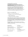
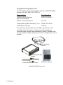
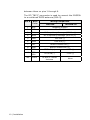
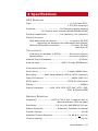
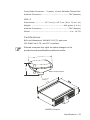
Manual
Simrad MX525A
DGPS Receiver
English
www.simrad-yachting.com
A brand by Navico - Leader in Marine Electronics
Manual
Simrad MX525A
DGPS Receiver
English Document no: 727007
Revision:
A
Date:
March 2008
The original language for this document is English. In the
event of any discrepancy between translated versions
and the English version of this document, the English
document will be the official version.
To the best of our knowledge, the content in this
publication was correct at the time of printing.
As we are continuously improving our products we
retain the right to make changes to the product and
the documentation at any time. Updated manuals are
available from our website www.simrad-yachting.com,
and are free to download.
© Copyright 2008 by Navico Holding AS.
IMPORTANT NOTICE!
THE MX525A DGPS RECEIVER IS AN AID TO
NAVIGATION ONLY. Under no circumstances should
it be used in lieu of authorized government charts.
Its accuracy can be affected by many factors such
as equipment defects, environmental conditions, or
improper operation. The user is responsible for safe
navigation of the vessel. This includes consulting
authorized government charts and exercising common
prudence and navigational judgement at all times.
How to contact us?
Contact your local Simrad dealer for:
•• Installation, Service, & Technical Support
•• Sales of Accessories
•• Hardware and Software Upgrades
Unlike many other consumer electronics industries which
only sell consumer electronic devices, your marine dealer
is often your best advisor for installation and service of
your new GPS receiver. Simrad strongly encourages you
to utilize the knowledge and experience of your sales and
service dealer.
Should you need to contact us directly for new sales,
upgrades, repair service, or technical support, we can be
reached at the following:
International:
In Europe:
MX Marine (USA)
Navico UK Ltd
A Division of NAVICO, Inc.
Premier Way, Abbey Park
23868 Hawthorne Blvd., Suite 201
Romsey, Hampshire
Torrance, California 90505
SO51 9DH
USA
United Kingdom
+1 310 791 8213 (Telephone)
+44 (0)1794 510010 (Telephone)
+1 310 791 6108 (Fax)
+44 (0)1794 510006 (Fax)
www.mx-marine.com
www.navico.com
2 | Simrad MX525A
Contents
1 General........................................................ 5
Supplied Equipment.......................................6
2 Operation.................................................... 7
General........................................................7
Satellite Bases Augmentation System (SBAS)....7
Receiver Autonomous Integrity Monitoring
(RAIM).........................................................8
3 Installation.................................................. 9
MX525A Mounting..........................................9
MX525A Connectors.......................................9
MGL-4 Antenna Mounting Guidelines............... 11
Antenna Mounting........................................ 12
Bracket Mount..................................... 12
Antenna Cable Selection............................... 13
Power Requirement...................................... 13
Power/Data Cable Assembly.......................... 14
MX525A Connector Configuration................... 15
Data Interface to MX420/2 or MK12 CDU......... 16
Data Interface to MX420/8 or MX420/AIS CDU. 17
Data Interface to MX5xx CDU........................ 18
Data Interface to PC or other navigation systems.
19
MX525A Programming Cable.......................... 20
4 Specifications............................................ 21
GPS Receiver ...................................... 21
Simrad MX525A | 3
Blank page
4 | Simrad MX525A
1 General
This manual describes the operation and installation of
the MX525A DGPS sensor (with the MGL-4 antenna) and
older version MX525 black box DGPS sensor (with the
MGL-3 antenna). Their wiring hook-up is identical and
the antennas are interchangeable.
The MX525A is a blackbox GPS and Differential Beacon
receiver combination. It has a 10-pin connector for power
and data connection and a TNC connector to connect to
an active GPS and Beacon combo antenna.
When connected to an MX-CDU (MX420 or MX5xx), the
MX525A can be controlled to function in several modes,
namely;
•• GPS only
•• DGPS mode in Auto/Database search or Manual
•• WAAS (Wide Area Augmentation System-US system)
•• EGNOS (European Geostationary Overlay System)
•• RAIM (Receiver Autonomous Integrity Monitoring)
This sensor was designed to use as:
•• Source of DGPS positioning for any MX CDU model
•• Retrofit for IMO compliant GPS and AIS installation
•• D/GPS positioning for ECDIS and other charting
software
The MX525A can achieve better than 2-meter accuracy
in areas with good beacon differential coverage and
autonomous GPS accuracy better than 5 meters. The
built-in beacon receiver can be operated to do autoglobal search, database search or manual mode when
connected to the MX CDU.
Before installing the MX525A, please read this manual
carefully to ensure proper installation and operation of the
unit.
General | 5
Supplied Equipment
The following items are supplied with the MX525A DGPS
Sensor Kit (p/n 9525 200 81000):
Description
Part Number
MX525A DGPS Sensor with mounting kit
9525 200 81010
MGL-4 Combo Antenna
721757
Power/Data Cable assembly, 3 m. 3508 102 70150
Installation Manual 727007
The antenna coax cable for the MGL-4 antenna is not
included in the kit and must be ordered separately.
Several cable lengths are available in stock, please refer
to the antenna cable selection section on Page 8 for more
details.
MGL-4 Combo
Antenna
Manual
MX525A
DGPS Receiver
MX525A Black Box
Sensor
www.simrad-yachting.com
3-meter Power/Data Cable
6 | General
A brand by Navico - Leader in Marine Electronics
Installation Manual
MX525A DGPS Sensor Kit
2 Operation
General
The MX525A sensor is an integrated GPS and beacon
receiver unit that is fully automatic and requires
minimal user intervention. It will automatically search
for available satellites as soon as power is applied. The
internal 2-channel beacon receiver continuously monitors
all beacon signals available in a particular location. The
first channel tracks the primary station while the second
channel searches for other nearby beacons. Should
it find a closer station it will automatically switch the
primary channel to the new station. The combined
performance of the high-precision 12-channel GPS and
2-channel beacon receiver provides a more accurate
position fix, usually within 2 meter or less.
When controlled by an MX CDU, the operator can disable
the auto mode and manually select the beacon frequency
desired.
The MX525A works with an MGL-4 (or -3) antenna (a
combined GPS/H-Field Beacon antenna) for better onboard electrical noise immunity.
Satellite Bases Augmentation System
(SBAS)
In areas where land-based beacon stations are not
available, the MX525A can be controlled (using the MX
CDU) to track the Satellite Based Augmentation Systems
(SBAS) like the WASS (US), EGNOS (European), MSAS
(Japan) and GAGAN (India) satellites . These satellites
transmit DGPS correction data (just like the Coast Guard
stations) using the GPS frequency. Refer to the MX CDU
Operator Manual for more details. Turning this feature
ON in the MX CDU will initiate the MX525A to track any
SBAS satellites that are in view. Please be aware that
the SBAS system is not an IMO approved differential
correction system.
Operation | 7
Receiver Autonomous Integrity
Monitoring (RAIM)
RAIM is a special software algorithm in the MX525A
program which provides another layer of safety because
it gives the operator an alarm indication if the GPS
system accuracy exceeds a predefined tolerance. This
feature requires at least five or more GPS satellites to
operate properly. If the position solution falls outside this
tolerance (usually 100 meter) a “RAIM Unsafe” alarm
will be activated in the MX420 CDU. This means that the
accuracy of the position can not be guaranteed at that
point in time. The operator is advised to use the GPS
for navigation with caution until the RAIM indicator goes
back to safe mode (R+).
The RAIM availability is dependent on the number of
usable satellites in view. Planned outage of satellites
due to maintenance or when certain satellites reach their
age of maturity may cause any of the GPS satellites to
become unusable. If less than 5 satellites are available
a “RAIM Caution” (R?) icon will be displayed. If the
GPS system error exceeds 100 meters “RAIM Unsafe”
(R-) icon will be displayed. The operator should take
cautionary measures during this mode.
8 | Operation
3 Installation
MX525A Mounting
The MX525A console is not weather-resistant and must
be located inside the equipment room or pilot house
where it is dry and protected from the elements. Provide
ample clearance around it for good air circulation. Use
the supplied mounting bracket kit to mount it on a
vertical wall.
Locate the MX525A within 3 meters from the MX CDU
junction box. Should there be a need to install the
MX525A much farther away from the MX420 CDU, a
longer cable assembly can be specially ordered from
Simrad.
The MGL-4 antenna is a weather resistant unit and should
be mounted in the open location as shown in the antenna
location diagram.
Below is a list of power-data cable options available from
Simrad:
Part Number
Description
3508 102 70150
3 meter cable
3508 102 70170
20 meter cable
3508 102 70180
40 meter cable
Special order only
80 meter cable
MX525A Connectors
Two connectors are located at the back of the unit,
namely:
•• Power-Data connector (10-pin male)
•• RF (TNC female)
The 10-pin connector provides the means to connect
to external power and the data interface. Please refer
to the chart below for the pin-outs and wiring color
code. The chart also compares the signal interface of
the MX525A DGPS sensor against the MX421B-10 smart
DGPS antenna. Please note the connection similarities
Installation | 9
between them on pins 1 through 8.
The RF (TNC-F) connector is used to connect the MX525A
to a combined DGPS antenna (MGL-3).
Pin #
1
10 | Installation
Wire
Color
BLK
Wiring Comparison
MX525A
MX421B-10
Negative Ground
2
RED
+9 - 32 VDC
3
BLU
MX Proprietary Message (MPM In (-)
4
BRN
MX Proprietary Message (MPM In (+)
5
ORG
GPS Out (-)
6
GRN
GPS Out (+)
7
YEL
Beacon Status Out (-)
8
WHT
Beacon Status Out (+)
9
PRPL
RTCM IN (+)
1 PPS (+)
10
PRPL/
GRY
RTCM IN (-)
1 PPS (-)
TNC
COAX
To MGL-3 Combo
Antenna
None
MGL-4 Antenna Mounting Guidelines
•• Install the MGL-4 antenna where it has clear view of
the sky around it.
•• Locate the antenna for easy access and maintenance.
•• Stay away from high-power energy sources such as
radar, SSB, INMARSAT and other transmitting radio
antennas by 5 meters or more.
•• Locate the antenna at least 10 feet (about 3 meters)
away from and out of the transmitting beam of radar
and other high-power transmitters.
•• Mount the antenna low to avoid excessive position and
speed errors while underway.
•• Mount the antenna as far away as possible from large
metal structures.
If you are not sure if the chosen antenna location is
appropriate, you can mount the MGL-4 antenna
temporarily and connect the coax cable to the MX525A.
Using the MX CDU, Monitor the GPS signals under the
“GPS Status” screen while you move the MGL-4 antenna
around.
VHF or MF
ANT.
3m
5 m (min.)
RADAR ANT.
INMARSAT
ANT.
MAIN
MAST
MGL-4
(or MGL-3)
ANT.
1m
10 m
(min.)
10 m
min.
Mount the MGL-3 Antenna
10 m (min.) forward of main mast
MGL-4 Antenna location diagram
Installation | 11
Antenna Mounting
Bracket Mount
The MGL-4 antenna mounting thread is an industry
standard fitting for VHF antenna mounting (1.0 inch, 14
TPI). This enables the antenna to be mounted on a wide
range of mounting brackets, including the swivel joints,
commonly used for angled surface. Refer to the figure
below for bracket mounting illustration.
Hand-tighten the antenna onto the bracket until snug. Do
not overtighten.
Secure with plastic
tie wraps
(not supplied)
12 | Installation
1”-14 TPI Stainless
Steel Mounting Bracket
(not supplied)
MGL-4 Bracket Mounting
Antenna Cable Selection
The table below gives recommendation on coaxial cables
that can be used for the MGL-4 GPS antenna. It is
important to keep the attenuation in the cable as low as
possible. The maximum allowable cable and connector
loss is 15 dB.
Coax cable
type
Max cable
length (m)
Diameter
(mm)
Weight
(kg/100m)
RG58
15
5.0
2.6
SAT45
45
5.5
2.6
RG223
25
5.4
5.5
RG214
45
10.8
18.5
LMR400
80
10.3
13.3
The chart below shows the antenna coax cables offered
by Simrad:
Part number
Description
3508 100 95780
15 meter, SAT45 cable (TNC-TNC)
3508 100 96010
20 meter, SAT45 cable (TNC-TNC)
3508 100 95910
30 meter, SAT45 cable (TNC-TNC)
3508 100 96020
45 meter, SAT45 cable (TNC-TNC)
Special order
>45 meter, Low-loss, Antenna cable
(TNC-TNC)
Power Requirement
External power supplied to the MX525A must be within 932 VDC for best operation. To protect the circuitry in the
MX525A, the voltage level must be within these limits.
Negative grounding is required. The MX525A draws less
than 300 mA at 12 VDC. An in-line fuse or circuit breaker
rated at 2 amp. is recommended for overload protection.
When the MX525A is connected to an MX CDU, the 12
VDC antenna power is supplied by the CDU unit.
Installation | 13
The red wire connects to the (+) DC power, while the
black wire is the negative return. Although the MX525A
has a reverse polarity protection, it is prudent to make
sure that proper polarity is observed before making the
connection.
Reverse polarity connection may damage the unit.
Power/Data Cable Assembly
Below is a diagram showing the pins and wire colorcoding of the Power/Data cable assembly.
10-Pin Female Connector
3.0 meters
Pin#
10
9
8
7
6
5
4
3
2
1
14 | Installation
Wire
Prpl/Gry
Purple
White
Yellow
Green
Orange
Brown
Blue
Red
Black
Signal
Ext. RTCM IN Ext. RTCM IN +
Beacon status Out +
Beacon Status Out GPS Out +
GPS Out MPM In +
MPM In +12-32VDC
Negative GND
Power/Data Cable Assembly
MX525A Connector Configuration
Refer to the diagram below for the POWER-DATA
connector located at the rear panel of the MX525A:
POWER
DATA
RF
?
??
?
?
?
?
?
?
?
?
TNC
Connector
Pin#
10
9
8
7
6
5
4
3
2
1
Wire
Prpl/Gry
Purple
White
Yellow
Green
Orange
Brown
Blue
Red
Black
Signal
Ext. RTCM IN Ext. RTCM IN+
Beacon status Out +
Beacon status Out GPS Out +
GPS Out MPM In+
MPM In +12-32VDC
Negative GND
MX525A POWER-DATA Connector
Where:
Pins 1 & 2:
Negative GND and +12 VDC power
input.
Pins 3 & 4:
MX proprietary message (MPM) input
port.
Pins 5 & 6:
GPS output to the MX420 or other
NMEA 0183 compatible devices.
Pins 7 & 8:
Beacon monitoring signal output. Sends
the SNR, Signal and Frequency to the
MX420/8 CDU. Connects to Cable B of
the MX420/8 CDU.
Pins 9 & 10: External RTCM Correction (Input).
Installation | 15
Data Interface to MX420/2 or MK12
CDU
Use the diagram below to interface the MX525A to an
MX420/2 or MK12 CDU.
MGL-4
Combo Antenna
Coax Cable
MX525A
Console
(16) Red/Wht
(1) Blk/Shield
(8) Org
(9) Org/Wht
MX420/2 or
Mk12 CDU
Cable A
(10) Yel
(11) Yel/Blk
(4) Brn
(5) Brn/Wht
(6) Prpl
(7) Prpl/Wht
(12) Grn
(13) Grn/Wht
(14) Blu
(15) Blu/Wht
(17) Gry
(18) Blk/Wht
(3) Blk
(2) Red
Red (+12 VDC)
Blk (GND)
Grn (GPS Out +)
Org (GPS Out -)
Brn (MPM In +)
Blu (MPM In -)
In (A)
In (B)
Out (A)
Out (B)
In (A)
In (B)
NMEA2 I/O
Out (A)
Out (B)
NMEA2 Tx (RS-232)
Ext. Alarm
Terminal strip
(User supplied)
16 | Installation
NMEA1 I/O
MX525A Interface to MX420/2 or MK12 CDUs
+
12-32VDC
Supply
Data Interface to MX420/8 or MX420/
AIS CDU
Use the diagram below to interface the MX525A to
an MX420/8 or MX420/AIS CDU. The external RTCM
connection is optional.
MGL-4
Combo Antenna
Coax Cable
MX525A
Console
(16) Red/Wht
(1) Blk/Shield
(8) Org
MX420/8 CDU
(9) Org/Wht
(10) Yel
(11) Yel/Blk
(6) Prpl
(7) Prpl/Wht
(12) Grn
Cable B
Cable A
(4) Brn
(5) Brn/Wht
(13) Grn/Wht
(14) Blu
(15) Blu/Wht
(17) Gry
(18) Blk/Wht
(3) Blk
(2) Red
Red (+12 VDC)
Blk (GND)
Grn (GPS Out +)
Org (GPS Out -)
Brn (LPM In +)
Blu (LPM In -)
In (A)
In (B)
NMEA1 I/O
Out (A)
Out (B)
In (A)
In (B)
NMEA2 I/O
Out (A)
Out (B)
NMEA2 Tx (RS-232)
Ext. Alarm
Terminal strip
(User supplied)
(4) Brn
(5) Brn/Wht
+
12-32VDC
Supply
White
Yellow
Purple
Ext. RTCM (-)
Ext. RTCM (+)
Purple/Grey
(Optional)
MX525A Interface to MX420/8 or MX420/AIS CDUs
Installation | 17
Data Interface to MX5xx CDU
The standard power/data cable (P/N 3508 102 70150)
for the MX525A and MX5xx CDU is pre-made with two
molded 10-Pin male connectors for an easy plug-andplay connection to the back of the MX5xx CDU. If there is
a need to extend (or cut) the standard cable, please refer
to the diagram below for the wire splice.
MX525A
MX 5xx CDU
P/N 3508 102 70150
3 MTR. CABLE ASSY.
MX 5xx CDU
MX525A
RED
BLK
RED
BLK
BLU
BRN
BLU
BRN
ORG
ORG
YEL
YEL
PRPL
PRPL
GRY
GRY
MX525A Interface to MX5xx CDU’s
18 | Installation
Data Interface to PC or other
navigation systems
The diagram below shows the power and data output
connections to the serial port of a PC or other navigation
systems using a dB9 connector and a terminal strip (user
MGL-4
Combo Antenna
Coax Cable
MX525A
Console
Brn (MPM In +)
Blu (MPM In -)
Grn (GPS Out +)
Org (GPS Out -)
Red (+12 VDC)
Blk (GND)
123456789
9dB PC connector
+
12-32VDC
Supply
supplied items).
MX525A Interface to other navigation systems
Installation | 19
MX525A Programming Cable
Secure cable with tie-wrap
MX525A
TD(A)
TD(B)
RD(A)
RD(B)
GND
+12V
RS422-RS232
Converter
12 VDC
MX525A Programming cable diagram
20 | Installation
B&B Electronics
RS422-RS232
Converter
Model 422LP9TB
PC
COM1
RS232
RS422
BRN
BLU
GRN
ORG
10-pin Male Connector
BLK
RED
3 meters
NEG
+12-32 VDC
The programming cable is used for upgrading the
software of the GPS and Beacon PCBs inside the MX525A
Console. The diagram below shows the programming
cable diagram and equipment setup. Please note that
external 12 volt DC is required to power up the MX525A.
Connect the red wire to +12 VDC and Black wire to
negative GND. The RS422-RS232 converter may be
powered from the PC serial port or from an external 12
volt power supply.
4 Specifications
GPS Receiver
Type:....................................................... L1, C/A Code (SPS) 1.575 GHz frequency
Channels:................................... 12 Channels, parallel tracking
(10-channel when tracking WAAS/EGNOS/MSAS)
Position Update Rate:...................1 Hz (default), 5 Hz (optional)
Position accuracy:
With differential corrections....................<2 meters 2D-RMS
depending on distance from differential base station.
Without differential corrections................ <5 meter 2D-RMS
(with S/A off)
Time to first fix:
Cold start (no almanac or RTCM): .......... 60 second (typical)
Reacquisition...................................... <10 second (typical)
Antenna Input Impedance:........................................ 50 Ohms
Antenna type:.................................MGL-3 Combo GPS/Beacon
Communications
Serial Ports:............................................ 2 duplex NMEA Ports
Baud Rate:........... 4800 baud (default), 9600 & 19200 (optional)
Data I/O Protocol:......................................... NMEA 0183 V3.0
RTCM Input: . ......................................... RTCM SC-104 format
Datum:...................................................................... WGS84
Output messages:......... GGA, GSA, GSV, GST, RMC, VTG, GRS,
ZDA, & (PMVXG,GBS)
Beacon Receiver
Frequency: .................... 283.5 to 325.0 kHz. 2-channel Auto or
Manual selection (500 Hz steps)
Sensitivity:............................2.5 uV/m for 6dB SNR @ 200 bps
Station Selection:..................... Automatic, Database or Manual
Dynamic Range: .........................................................100 dB
Adjacent Channel Rejection:....................... 61 dB @ f + 400 Hz
Channel spacing:.........................................................500 Hz
Specifications | 21
Frequency offset tolerance: ......................................... + 5 Hz
Antenna type:............................................................ H-Field
MSK rates:...............................................50, 100 and 200 bps
Environmental
MX525A Console
Operating Temperature:..................................... -30 to +55 °C
Storage Temperature:........................................-40 to +85 °C
Humidity:..................95% non-condensing, protected category
MGL-3 Antenna
Operating Temperature:..................................... -30 to +70 °C
Storage Temperature:........................................-40 to +85 °C
Splashproof:.......................... “Exposed Category” (IEC 60945)
Electrical
MX525A Console
Operating Voltage:........................................... 10.5 to 32 VDC
Reverse Polarity Protection:...............................................Yes
Operating current:
.............................< 230 mA at 12.0 VDC,
Power Consumption:................................................ <3 Watts
Antenna Supply Voltage:......................... 5 VDC (100 mA max.)
Interface Cable:........... 3-meters, 10-wire Shielded Twisted Pair
MGL-3 Antenna
Operating Voltage:................................................5 to 12 VDC
Power Consumption:.................................................. <1 Watt
Mechanical
MX525A Console
Dimensions:........................... 13.5 (L) x 11.4 (W) x 3.7 (H) cm.
Weigh:...............................800 grams (1.7 lb.) (without cable)
Mount:...................................................U-Bracket (provided)
22 | Specifications
Power/Data Connector:... 3-meter, 10-wire Shielded Twisted Pair
Antenna Connector:............................................ TNC (female)
MGL-3
Dimensions:................ 12.7 cm (L) x 12.7 cm. (W) x 7.6 cm. (H)
Weight: ....................................................460 grams (1.0 lb.)
Antenna Connector:............................................ TNC (female)
Mount:............................................................... 1 in.- 14 TPI
Certifications
BSH and Wheelmark IMO MSC 112(73) approved
IEC 60945 ed.3, CE, and FCC compliant
Simrad reserves the right to make changes in its
products and specifications without notice.
7.6 cm (3”)
12.7 cm (5”)
MGL-4 Combo Antenna
1”-14 TPI
Mount
.5
13
cm
MX525A Console
Specifications | 23
Blank page
24 | Specifications
5 Data Output
The MX525A data output conforms to the NMEA
0183 V3.0 at 4800 baud. Below is a list of the NMEA
sentences output:
NMEA 0183 V3.0: GGA, GLL, GSA, GSV, GST, RMC and
VTG
NMEA 0183 Data Output Sentences
(1) GGA - Global Positioning System Fix Data
Time, position and fix related data for a GPS receiver.
$GPGGA,hhmmss,llll.llll,a,yyyyy.yyyy,a,x,xx,x.x,x.x,M,x.x,M,x.x,xxxx*hh<CR><LF
1
2 3
Notes:
4
5 6 7 8 9 10 11 12 13 14
1 ----- UTC of position
2,3 --- Latitude - N/S
4,5 --- Longitude - E/W
6 ----- GPS Quality Indicator:
0 = Fix not available or invalid
1 = GPS SPS Mode, fix valid
2 = Differential GPS, SPS Mode, fix valid
3 = GPS PPS Mode, fix valid
7 -----Number of Satellites in use, 00-12, may
be different from the number in view
8 -----Horizontal Dilution of Precision (HDOP)
9 ----Antenna altitude/mean-sea-level (geoid)
10----Units of antenna altitude, Meters
11,12-Geoidal Height, Meters
13----Age of Differential GPS Data
14 --- Differential Reference Station ID
Data output | 25
(2) GLL - Geographic Position - Latitude/Longitude
Latitude and Longitude of vessel position, time of
position fix and status.
$GPGLL,llll.llll,a,yyyyy.yyyy,a,hhmmss.ss,A,a*hh<CR><LF
1 2
3
4
5
6
Notes:
1,2 ------- Latitude, N/S
3, 4 -------Longitude, E/W
5 -----------UTC of position
6 -----------Position system Mode Indicator:
A=Autonomous mode
D=Differential mode
E=Estimated (DR) mode
M=Manual input mode
S=Simulator mode
N=Data not valid
(3) GSA - GPS DOP and Active Satellites
GPS receiver operating mode, satellites used in the
navigation solution reported by the $GPGGA sentence,
and DOP values.
$GPGSA,a,x,xx,xx,xx,xx,xx,xx,xx,xx,xx,xx,xx,xx,x.x,x.x,x.x*hh<CR><LF>
1 2 3 4 5 6 7 8 9 10 11 12 13 14 15 16 17
Notes: 1---- Mode: M = Manual, forced to operate in 2D or 3D Mode
A = Automatic, allowed to automatically switch 2D/3D
2 ---- Mode: 1 = Fix not available, 2 = 2D, 3 = 3D
3-14 -PRN numbers of satellites used in solution (null for unused fields)
15 ---PDOP
26 | Data output
16 ---HDOP
17 ---VDOP
(4) GSV - GPS Satellite in View
Number of satellites (SV) in view, PRN numbers,
elevation, azimuth and SNR values. Four satellites
maximum per transmission, additional satellite data sent
in second or third message. Total number of messages
being transmitted and the number of the message
transmitted are indicated in the first two fields.
$GPGSV,x,x,xx,xx,xx,xxx,xx,....................,xx,xx,xxx,xx*hh<CR><LF>
1 2 3 4 5 6 7
8
9 10 11
12
Notes: 1 -----Total number of messages, 1 to 3
2 ---- Message number, 1 to 3
3 ---- Total number of satellites in view
4 ----- Satellite PRN number
5 ----- Elevation, degrees, 90 degrees maximum
6 ------Azimuth, degrees True, 000 to 359
7 ------SNR (C/No) 00-99 dB, null when not
tracking
8 ------2nd and 3rd SV
9,10,11,12
- 4th SV
(5) RMC - Recommended Minimum Specific GPS Data
Time, date, position, course and speed data provided by
a GPS navigation receiver. This sentence is transmitted
at intervals not exceeding 2 seconds. All data fields
must be provided: null fields used only when data is
temporarily unavailable.
$GPRMC,hhmmss.ss,A,llll.llll,a,yyyyy.yyyy,a,x.x,x.x,xxxxxx,x.x,a*hh<CR><LF>
1
2
Notes:
3 4
5
6 7 8
9
10 11
1 ----
UTC of Position fix
2 ----
Status: A = data valid
V = Navigation receiver warning
Data output | 27
3,4 --
Latitude, N/S
5,6 --
Longitude, E/W
7 ----
Speed over ground, knots
8 ----
Course Over Ground, True
9 ----
Date: dd/mm/yy
10,11 - Magnetic variation, degrees E/W.
Easterly variation (E) subtracts from
True course, Westerly variation (W) adds
to True course.
(6) GST - GNSS Pseudorange Error Statistics
This message is used to support Receiver Autonomous
Integrity Monitoring (RAIM). Pseudorange measurement
error statistics can be translated in the position domain
in order to give statistical measures of the quality of the
position solution.
If only GPS, GLONASS, etc. is used for the reported
position solution, the talker ID is GP, GL, etc., and the
error data pertains to the individual system. If satellites
from multiple systems are used to obtain the reported
position solution, the talker ID is GN and the errors
pertain to the combined solution.
$GPGST,hhmmss.ss,x.x,x.x,x.x,x.x,x.x,x.x,x.x*hh<CR><LF>
1
Notes:
2
3
4
5
6
7
8
1 ---- UTC time of the GGA or GNS fix associated
with this sentence.
2 ---- RMS value of the standard deviation of the
range inputs to the navigation process.
Range inputs include preudoranges & DGNSS corrections.
3 ---- Standard deviation of semi-major axis of
error ellipse (meters)
4 ---- Standard deviation of semi-minor axis of
error ellipse (meters)
5 ---- Orientation of semi-major axis of error
ellipse (degrees from true north)
28 | Data output
6 ---- Standard deviation of latitude error
(meters)
7 ---- Standard deviation of longitude error
(meters)
8 ---- Standard deviation of altitude error
(meters)
(7) VTG - Course Over Ground and Ground Speed
The actual course and speed relative to the ground.
$GPVTG,x.x,T,x.x,M,x.x,N,x.x,K,a*hh<CR><LF>
1 2 3 4 5 6 7 8
9
Notes: 1,2 ----Course over ground, degrees True
2,3 ----Course over ground, degrees Magnetic
5,6 ----Speed over ground, knots
7,8 ----Speed over ground, km/hr
9 ------Mode indicator: A = Autonomous mode
D = Differential mode
E = Estimated (DR)
M = Manual input mode
S = Simulator mode
N = Data not valid
(8) ZDA -Time and Date
UTC, day, month, year and local time zone
$GPZDA,hhmmss,xx,xx,xxxx,xx,xx*hh<CR><LF>
1
2 3
4
5 6
Notes: 1 --- UTC
2, 3, 4 --- Day, month & year
5 --- Local zone hours, 00 to + 13 hrs.
6 --- Local zone in minutes, 00 to +59.
Data output | 29
(9) GBS - GNSS Satellite Fault Detection (Modified MX
version)
This message is used to support Receiver Autonomous
Integrity Monitoring (RAIM) feature in the MX420 CDU. A
special character flag was added for proper RAIM status
determination.
$PMVXG,GBS,hhmmss.ss,x.x,x.x,x.x,xx,x.x,x.x,x.x,x*hh<CR><LF>
1
Notes:
2
3 4
5 6 7
8
9
1 ----- UTC time of the GGA or GNS fix
associated with this sentence.
2 ----- Expected error in Latitude (meters)
3 ----- Expected error in Longitude (meters)
4 ----- Expected error in Altitude (meters)
5 ----- ID number of most likely failed satellite
6 ----- Probability of missed detection for most
likely failed satellite
7 ----- Estimate of bias in meters on most likely
failed satellite
8 ----- Standard deviation of bias estimate
9 ----- RAIM status mode; 0=safe, 1=caution,
2=unsafe
30 | Data output
How are we doing?
Please help us to help you and our other valued
customers by sending us your evaluation of this manual.
We need to know such things as:
-- is the manual complete, or do you need more (or less)
information?
-- can you find the information you need easily?
-- is the information easy to understand, or could we be
clearer?
-- are there any errors and, if so, where and what are
they?
Be sure to reference the title and identification number
of this manual.
Please email your comments to: [email protected].
We look forward to finding out how we can improve our
information services.
All of your comments and suggestions become the
property of Navico Holding AS.
Data output | 31
Blank page
32 | Data output
Doc.no.727007, Rev.A