1
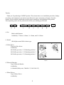
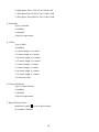
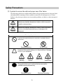
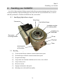
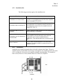
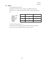
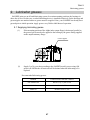
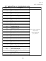
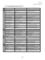
Optimum Reliability in Motion Control
SERVO DRIVE TYPE
OPERATION AND MAINTENANCE MANUAL
ALPHA SERVO DRIVE INDEX
11AR
Preface
Thank you for purchasing a SANDEX product. These instructions cover installation procedures, linkage
procedures, and maintenance precautions to be followed to ensure maximum performance from this
product. Please read these instructions carefully before installing or trial operating of this product.
After unpacking, make sure the product delivered fits your ordering specifications.
9
AR
|
a
|
b
-
S01
A
0
0
0
0
X
|
c
|
d
|
e
|
f
|
g
|
h
|
I
a: Size
Shaft to shaft distance
Availability: 7=70mm, 9=90mm, 11=110mm, and 15=150mm
b: Model
AR=Alpha series Roller drive type
c: Roller Drive
Type of roller drives
Availability:
S01=Roller gear ratio; 1/12, Mounting position; 1
S02=Roller gear ratio; 1/12, Mounting position; 2
S05=Roller gear ratio; 1/12, Mounting position; 5
April 2002
d: Motor & Bracket
Type of Motor & Bracket
Availability:
A=Standard (Pulley ratio; 7&9AR=1/3, 11&15AR=1/2)
e: Motor Driver
Type of Motor Driver
Availability:
1
0=Single phase 200 to 230VAC for 7AR & 9AR
1=Three phase 200 to 230VAC for 11AR & 15AR
2=Three phase 380 to 480VAC for 11AR & 15AR
f: Controller
Type of controller
Availability:
0=Standard
x=Special requirements
g: Cable
Type of cables
Availability:
0=3 meters length, w/o conduit
1=5 meters length, w/o conduit
2=10 meters length, w/o conduit
3=15 meters length, w/o conduit
4=3 meters length, w/ conduit
5=5 meters length, w/ conduit
6=10 meters length, w/ conduit
7=15 meters length, w/ conduit
Y=Connectors Only
h: Control Software
Type of control software
Availability:
0=Standard
x=Special requirements
I: Special Instructions
Include the symbol X in case of special orders
No symbols= Standard
2
Safety Precautions
S ymbols to ensure the safe and proper use of the Variax
The following symbols are used this manual where safety precautions must be observed. Read
and understand the meanings of these symbols to ensure the safe and proper use of Variax.
Failure to obey these precautions can cause machine problems, accidents, or other unexpected
behavior.
Warning
Caution
Indicates a potentially hazardous situation, which may result
in death or serious injury.
Indicates a potentially hazardous situation, which may result
in minor or moderate personal injury or damage to the
equipment.
Meaning of symbols
In general, this symbol alerts you to an action or operation that you
must not do.
General prohibition
Do Not Touch
In general, this symbol alerts you to the possibility of damage
to you or your equipment.
General
Warning
Electrical
Hazard
Pinch Point
High
Temperature
This symbol alerts you to actions that are reserved for
qualified service personnel only
Electrical Grounding
Mandatory Action
3
Contents
PREFACE
SAFETY PRECAUTIONS
SAFETY PRECAUTIONS
3
SYMBOLS TO ENSURE THE SAFE AND PROPER USE OF THE VARIAX
3
1. OPERATING THEORY
6
2. HANDLING YOUR SANDEX
SANDEX
7
2.1
IDENTIFYING ALPHA SERVO LAYOUT
7
3. TRANSPORTATION AND
AND ENVIRONMENT
3.1
3.2
3.3
3.4
SHIPPING CONDITION
TEMPERATURES
MOISTURE
DUST
8
8
8
8
8
4. INSTALLATION
10
4.1 CASING MAIN BODY
4.2 DRIVER
10
10
4.2.1
STORAGE CONDITIONS
4.2.2
INSTALLATION SITE
4.2.3 ORIENTATION
4.2.4 WIRING THREE PHASE 200VAC
200VAC
4.2.5 WIRING THREE PHASE 400VAC
400VAC
4.3 CONTROLLER
4.3.1
MOUNTING THE MP940
4.3.2 CONNECTION OF PERIPHERAL
PERIPHERAL DEVICES
4.4 WIRING
4.4.1 I/O CIRCUITS
4.4.2 CONTROLLER I/O CONNECTIONS
CONNECTIONS
14
5.OPERATION
16
19
5.1 SETTING ENCODER ZERO POSITION
5.2 SETTING ZERO POSITION (STARTING POSITION)
5.3 I/O TIMING CHART WHILE IN
IN JOG MODE
5.4 I/O TIMING CHART WHILE IN AUTOMATIC MODE
5.5 INDEXING TIME VS. STOPS CHART
4
19
19
20
21
22
10
11
11
12
13
14
15
17
18
5.6 DATA SWITCH SETTINGS
22
6. HANDLING PROCEDURES
PROCEDURES FOR THE OUTPUT SHAFT
6.1 TABLE TYPE OUTPUT
23
7. LUBRICATION
4.5
7.2
7.3
7.4
23
24
PURPOSE OF LUBRICATION
LUBRICATION
OIL SELECTION PRECAUTIONS
PRECAUTIONS
LUBRICATING OIL VISCOSITY
VISCOSITY’S
RECOMMENDED LUBRICATING
LUBRICATING OIL
24
24
25
25
8. FILLING AND REPLACING
REPLACING LUBRICATING OIL
OIL
26
8.1 REFILLING LUBRICATING OILS
SCHEDULE
8.2 OIL REPLACEMENT SCHEDULE
26
26
9. LUBRICATION GREASES
GREASES
27
9.1 SUPPLYING LUBRICATING GREASE
27
10. REPAIRS AND MAINTENANCE
MAINTENANCE
28
10.1 YASKAWA DRIVER AND CONTROLLERDISPLAY CODES
CODES
10.2 TROUBLESHOOTING PROCEDURES
PROCEDURES (1)
10.3 TROUBLESHOOTING PROCEDURES
PROCEDURES (2)
5
29
31
32
Unit 2
Handling your Sandex
1. Operating theory
SANDEX units operate based on the following principal. A globoidal cam is mounted onto the input
shaft. This cam interlocks with the turret portion of the output shaft. The turret has cam followers along
its perimeter, which are in contact with the tapered ribs on the cam. This contact or pressure is called
the preload. Turning the input shaft rolls the cam followers along the rib surfaces thereby rotating the
turret according to the curve of the cam. The turret is motionless when the ribs are parallel with the
edges of the cam although the cam followers stay in motion.
Two of three cam followers are always kept pressed against the tapered ribs to ensure an accurate
transmission of rotation. Any backlash or movement between the tapered rib surfaces and cam
followers can cause vibrations, noise, and also damage the cam and cam follower surfaces. Backlash
can be completely eliminated by rotating the eccentric flange that holds the input shaft, and minimizing
the distance between the input and output shaft.
Explanation of terms used with indexing equipment
TERM
Number of stops
DEFINITION
The number of stops determined by the customer’s programming.
A predetermined number of stops have been programmed into the
controller (1-16) CW or CCW.
Index angle
The index angle is dependant on the number of stops.
Dynamic Torque output
rating(Top)
The maximum torque that can be applied on the output shaft
during indexing phases. Directly related to machine life.
6
Unit 2
Handling your Sandex
2. Handling your SANDEX
Over 90% of the mechanical failures reported with roller gear cam equipment comes from careless
or improper handling. Improper handling not only reduces the life of your SANDEX unit, it can also
affect the performance of both the SANDEX unit and your machine.
2.1
Identifying Alpha Servo layout
Roller Drive
Servomotor
Fixed hollow flange
Installation surface
for indexing table.
Installation for
fixed table.
Servomotor
mounting bracket
Oil cap
Oil gauge
*Drain
Mounting hole
at W-surface
2.2 Handling your Alpha Servo
(1)
Torsion and deflection within the rotation transmission system
(2)
Frictional torque within the rotation transmission system
(3)
Frequent load charge
(4)
Usage under rust stimulant conditions such as water, acid, or alkali
(5)
Usage in dusty areas
(6)
Electrical currents
(7)
Improper maintenance and repairs
(8)
Mounting areas with insufficient rigidity
7
Unit 3
Transportation and environment
3. Transportation and Environment
3.1 Shipping condition
(1) All SANDEX products are thoroughly inspected after the final assembly. Only those
products that pass this inspection are shipped.
(2) Before shipped, each SANDEX unit is filled with lubrication oil in accordance to the
customer’s operating speed and environment.
(3) A rust preventative solution is applied to the input /output shafts, key, and mounting
surface. Vinyl tape is also used extensively to protect your SANDEX unit from
scratches while transporting.
Remove the rust preventative solution with a light oil or thinner. Be careful not to let the
light oil or thinner contact the oil seal. Never use thinner on or near the plastic sight gauge.
This may cause severe clouding of the material.
3.2 Temperatures
(1)
For use between -20 to 0 degrees Celsius, (-4 to 32°F) use a lubricating oil with a lower
viscosity than the recommended oil. This is because the dynamic viscosity of the
lubricating oil rises in low temperatures and may not allow proper speed acceleration.
(2)
For use between 40 to 70 degrees Celsius, (104 to 158°F) use lubricating oil with a
higher viscosity than the recommended oil. This is because the dynamic viscosity of the
lubricating oil lowers in higher temperatures and reduce the life of the equipment.
(3)
For use between 70 to 100 degrees Celsius, (158 to 212°F) replace the oil seal and O-ring
with a heat resistant synthetic rubber.
3.3 Moisture
Rust may occur in storage or if the main machine is washed with water. Water does not
have to come directly into contact with the unit to cause rust. Moisture, condensation, and
other sources of humidity can also cause rust.
To use under these conditions, the mounting surfaces and shafts of the unit must be
painted, or otherwise rust proofed. Applying mineral oil or grease to the mounting surfaces
has a rust preventative effect and should always be practiced.
In addition, if the unit is directly subject to water, the sealing devices on the input and
output must be changed to a waterproof construction.
3.4 Dust
SANDEX units are generally built resistant to dust. This is because the roller gear cam
mechanism is enclosed within its own housing, and then sealed off at the input and output
with an oil seal. However, depending on the amount of dust or other foreign particles, the
8
Unit 3
Transportation and environment
oil seal may wear and thereby cause oil leaks. This is particularly evident when chemicals
are used. Chemicals can also cause and or accelerate rust and corrosion. When using
your SANDEX unit in dusty areas, you should consider using protective covers made from
stainless steel or plastic.
If the location for your SANDEX unit is very dusty, the air outlet in the oil
fill port may become an entrance into the housing. Placing an air filter over
this port should prevent dust from entering the housing. Electrical currents
If electricity passes through the SANDEX unit, minute dimples can occur on the cam
followers and roller gear cam, as well as on the rolling surfaces and members of the
bearings.
“ Electrolytic corrosion” is where electrical sparks actually melt away the surfaces of
the rolling members. Electrolytic corrosion is a current-based effect. Therefore, it can
occur under less than one volt of electrical power.
If your SANDEX unit may be subject to electrical currents, make sure to insulate it.
Electrolytic corrosion, if allowed to persist, will increase the amount of vibration and noise,
and eventually render your SANDEX unit useless. Always insulate the table and unit from
welding applications or other automated machinery that use large amounts of electrical
current.
When linking the motor with the input system, consider using rubber couplings instead
of metal types. Rubber provides more insulation. Other measures that can prevent
electrolytic corrosion include using V-belts and timing belts.
9
Unit 4
Installation
4. Installation
Another crucial factor to the performance of your SANDEX unit is the operating environment. Make an
early review of the location for your SANDEX unit and take any corrective actions necessary.
4.1 Casing main body
(1) Always use the lifting bolt holes provided on the housing of your SANDEX unit. Do not lift
the unit using the input or output shafts as this can affect the precision of the equipment, or
worse, affect the life of the machine.
(2) Each SANDEX unit has oil fill, drain and sight gauge ports. The unit should be mounted for
easy maintenance access to these ports.
(3) To ensure that your SANDEX unit is mounted accurately in the best possible position, make
sure the housing, shaft dimensions, and mounting holes comply with drawing specifications.
Also check the mounting area for perpendicularity and flatness. If the mounting surface has
any scratches, burrs, debris, or paint, use an oilstone or emery paper to remove it. Next,
clean the mounting surface and apply a light coat of grease or mineral oil to prevent rust
and scratches. You may now mount your SANDEX unit. Never install the unit in a position
not specified for your particular product.
(4) Align your peripheral equipment with the input and output shafts on the SANDEX unit to
ensure the best possible mounting position.
Apply Loctite 242 or equivalent screw locking solution to the mounting bolts, and tighten to
the specified torque with a torque wrench. (Tightening torque: DIN 8.8)
(5) The foundation for your SANDEX unit must be rigid enough to withstand vibrations from
other machines. The foundation is crucial to the precision and life of your SANDEX unit.
To ensure maximum performance mounts your SANDEX unit on a foundation that is
smooth, flat, hard, and free from vibration.
The standard operating temperature range for SANDEX units is between 0 to 40 degrees
Celsius (32 to 104°F). For usage outside of this range, follow the tips below.
4.2 Driver
The SGDH servo amplifiers are base-mounted. Incorrect installation will cause
problems. Follow the installation instructions below.
4.2.1
Storage Conditions
Store the servo amplifier within the following temperature range, as long as it is
stored with the power cable disconnected. -20 to 85°C (-4 to 185°F)
10
Unit 4
Installation
4.2.2
Installation Site
The following precautions apply to the installation site
Situation
Installation Precaution
Installation in a Control Panel
Design the control panel size, unit layout, and cooling
method so the temperature around the servo amplifier
does not exceed 55°C (131°F).
Installation Near a Heating Unit
Minimize heat radiated from the heating unit as well as
any temperature rise caused by natural convection so
the temperature around the servo amplifier does not
exceed 55°C (131°F).
Installation Near a Source of
Vibration
Install a vibration isolator beneath the servo amplifier to
avoid subjecting it to vibration.
Installation at a Site Exposed to
Corrosive Gas
Corrosive gas does not have an immediate effect on the
servo amplifier, but will eventually cause electronic
components and contactor-related devices to
malfunction. Take appropriate action to avoid corrosive
gas.
Other Situations
Do not install the servo amplifier in hot and humid
locations or locations subject to excessive dust or iron
powder in the air.
4.2.3 Orientation
Install the servo amplifier perpendicular to the wall as shown in the figure. The servo
amplifier must be oriented this way because it is designed to be cooled by natural convection
or by a cooling fan. Secure the servo amplifier using the mounting holes. The number of
holes varies (from two to four) with the frame size of the servo amplifier.
11
Unit 4
Installation
4.2.4
Wiring Three Phase 200VAC
12
Unit 4
Installation
4.2.5 Wiring Three Phase 400VAC
13
Unit 4
Installation
4.3 Controller
4.3.1
Mounting the MP940
1. Insert the two mounting tabs on the bottom of the MP940 into the mounting holes
on the lower right side of the SGDH.
2. Pressing in the direction of the arrows, insert the mounting tabs on the top of the
MP940 into the mounting holes on the top right side of the SGDH.
3. Insert the MP940 module fixing spring into the hole on the top of the SGDH.
4. While pulling on the fixing spring, pull the spring mounting hook on the top of
the MP940 case.
5. Mount the bottom spring in the same manner as in step 4. Refer to the
following diagrams when mounting the MP940 to a servo amplifier. There are
two kinds of mounting springs; they differ in shape according to the servo
amplifier capacity.
14
Unit 4
Installation
4.3.2 Connection of Peripheral Devices
Switch Box Or PLC
Motor power, and encoder are standard cables that are supplied by Sankyo America
Inc. The I/O connections are made by one of two options (see 4.4.2). The source power
cables will be supplied by the customer.
15
Unit 4
Installation
4.4
Wiring
1.) Power Supply Connector Cable
Supplies DC +24V 400mA power supply to the MP940 module. The
connectors use a screw-mount terminal block BL3, 5/3F-AU (Weidmuller,
Inc.).
Pin#
Signal Name
Name
3
+24V
+24VDC input
2
GND
0V
1
FG
Frame ground
2.) Input Cable Preparing Procedure
Use a twisted pair with a wire size of AWG#24 to AWG#20 when connecting the
24VDC power supply and MP940 Module power supply connector.
16
Unit 4
Installation
4.4.1 I/O Circuits
17.4-28.8VDC
5.3mA rated
current
24V 100mA
output load
signals
17
Unit 4
Installation
4.4.2 Controller I/O connections
The pigtail cable, and the cable with terminal
block are available options for your connection
Note: N/A connections are not
needed for the Alpha Servo
application.
18
Unit 5
Operation
5.Operation
Generally, automated machinery using SANDEX units are complicated in design. This is based on the
large number of linkage involved. Such machinery generally uses the cams and linkages for obtaining
overlapped movements. However, one will almost always encounter interference problems if he operates
the equipment prematurely. To avoid this type of problem, the input drive should be test turned by hand,
as each component is mounted.
5.1 Setting encoder zero position
a) Press the DSPL/SET key to select the auxiliary function mode.
F n 0 0 0
b) Select the user constant Fn008. Press the or cursor key to select the digit to set, and
then press the or cursor key to change the number.
F n 0 0 8
c) Press the DATA/ENTER key for the following display to appear.
d) Using the cursor key change this
P G L C 1
P G L C 1
value to
e) When the display reads “PGCL5” press the DISPL/SET key then the display will flash
“done” for one second then return to “PGCL5”.
d o n e
f) Reset the 24VDC power to finish the absolute encoder’s setup operation.
5.2 Setting zero position (starting position)
The Sankyo Alpha series index drive is equipped with a servomotor as part of our standard
package. Manual adjustment for positioning and timing purposes of the indexing drive can
easily be accomplished by using the jog feature. After entering jog mode and locating zero
position (starting point) exit jog mode. Once the jog mode has been exited the zero position
will be established. Once this method has been completed please do not enter the jog mode
unless you wish to reset the zero position.
19
Unit 5
Operation
5.3 I/O timing chart while in jog mode
A) Input Signals
1) Servo ON: This signal will activate the driver and await user commands. If there are no errors
the ready output signal will also be activated.
2) Auto/Jog: This signal will cause the controller to go into jog mode and await a start signal.
3) Start: While in jog mode this signal will start the rotation of the motor’s output shaft. When
this signal is not present the motor will stop rotating.
4) CW/CCW: This signal will cause the servomotor to jog in a counterclockwise (CCW)
direction. When this signal is not activated the motor will jog in a clockwise (CW) direction.
B) Output Signals
1) Ready: This signal will be activated when there are no errors, and the drive is on.
2) Alarm: This signal will be activated whenever there is an alarm present in the drive.
3) Busy: This signal will be activated whenever the drive senses movement of the motor.
20
Unit 5
Operation
5.4 I/O timing chart while in automatic mode
C) Input Signals
1) Servo ON: This signal will activate the driver and await user commands.
If there are no errors the ready output signal will also be activated.
2) Auto/Jog: This signal is not activated causing the controller to begin auto mode and
await a start signal.
3) Start: While in auto mode this signal will start the preprogrammed motion that was
written by Sankyo America. Each of these units will be programmed in accordance
with the customer’s specifications.
4) CW/CCW: This signal will cause the servomotor to execute the preprogrammed
motion in a counterclockwise (CCW) direction. When this signal is not activated the
motion will rotate in a clockwise (CW) direction.
21
Unit 5
Operation
5.5 Indexing time vs. stops chart
Index time- # Stops chart
3.5
3.0
Index time in seconds
2.5
2.0
1.5
1.0
0.5
0.0
1
2
3
4
5
6
7
8
9
10
11
12
13
14
15
16
# Stops
5.6 Data switch settings
Program#
0
1
2
3
4
5
6
7
8
9
10
11
12
13
14
15
3 bit
Data
2 bit 1bit
0bit
Stops
1
2
3
4
5
6
7
8
9
10
11
12
13
14
15
16
On
On
On
On
On
On
On
On
On
On
On
On
On
On
On
On
On
On
On
On
On
On
On
On
On
On
On
On
On
On
On
On
22
Index Angle
[degree]
360
180
120
90
72
60
51.42857
45
40
36
32.72727
30
27.69230
25.71428
24
22.5
Index time
[sec]
3.172
1.636
1.124
0.868
0.714
0.612
0.539
0.484
0.441
0.407
0.379
0.356
0.336
0.319
0.305
0.292
Unit 6
Handling Procedures
6. Handling procedures for the output shaft
The output shaft on an indexing drive is subject to momentous torque during starting
and stopping. Therefore, the shaft must be torsionally rigid. To maintain positioning
accuracy, the output shaft must have minimal run out. The run out on a standard SANDEX
is within 0.02 mm (.0008 ).
Note
The SANDEX is designed to show accuracy as it stops. When aligning shafts, do so after
repeated indexing and make sure the shaft is in a dwell.
There are different handling methods for various configurations of the final turret. The
following indexing drive handling procedures also apply for roller drives and oscillating
drives.
6.1 Table type output
(1)
Table type output sections have a broader mounting surface than flange type output.
Tables can be mounted easily and accurately.
(2)
To accurately position work stations on the table, enlarge the hole in the center of the
table from 0.1 to 0.2 mm (.004 .008 ). Align the table. Then, tighten the bolts and
drive locating pins into place. Our recommendation of size of bolts and tighten torque is
as following.
7AR
9AR
11AR
15AR
(3)
Mounting bolts
Size
Tighten torque
6-M6
13.5 N· m
6-M6
13.5 N· m
6-M8
34 N· m
6-M10
67.5 N· m
Recommended knock pin
Place
Hole depth
P.C.D. 85
12 mm
P.C.D. 120
12 mm
P.C.D. 150
16 mm
P.C.D. 210
20 mm
The center of output shaft has a fixed flange with a hole in it. This fixed flange is suitable
for directly mounting fixed tables. A hole can be drilled in the mounting base in line with
the center of the output shaft for concealing wiring and plumbing.
Through-hole
Fixed table
Indexing Table
Table-type
Mounting
b
23
Unit 7
Lubrication
7. Lubrication
Lubrication is an effective and vital means for maintaining the life of your SANDEX unit.
Lubrication can minimize wear by reducing friction between rolling members, removing friction heat,
and preventing rust on rolling surface. The statistical life of the SANDEX unit is based on rolling
fatigue. However, these statistics are valid only when wear, vibration, and mechanical seizure are kept
at a minimum.
Improper lubrication over any of these areas can cause frictional wear in a very short time.
On the other hand, proper lubrication using incorrect grades of lubricating oils, such as low viscosity
oil, can cause temperature rises and lower the dynamic viscosity of the lubricant. This means that the
minimum dynamic viscosity necessary for forming an oil film cannot be obtained, thereby allowing the
two surfaces to directly come into contact and cause frictional wear.
It is vitally important that proper lubrication procedures be implemented according to actual
operating conditions.
4.5
Purpose of lubrication
(a)
To prevent friction between pure slipping members.
(b)
To prevent abrasion by forming an oil film between two surfaces, thereby inhibiting
direct contact between both surfaces.
(c)
To extend the fatigue life of the material by introducing boundary based on oil film
formation, thereby relieving Hertz stress.
(d)
To prevent local temperature rises by transmitting and removing friction heat.
(e)
To prevent dirt and other foreign particles from entering the housing.
(f)
To prevent rust by using the oil film to keep the surface from direct exposure to the
atmosphere.
7.2 Oil selection precautions
(1)
Lubrication is a vital factor to ensure maximum performance from your unit. The
selection of lubricating oils is equally important. Improperly selected oils can lower
the precision of the unit, and reduce its operating life. When selecting an oil, always
give full consideration to actual operating conditions.
(2)
When selecting oils, choose good quality gear oil with pressure additives, a strong
oil coating quality, rust inhibiting properties, and steady oxidation. (A pressure
additive is a specially formulated chemical composition that improves lubrication
performance.)
(3)
Never mix oils of different manufacturers even if they are used for the same purpose.
This is because each manufacturer may use pressure additives with different
compositions.
24
Unit 7
(4)
(5)
Lubrication
Viscosities differ according to the operating speed and size of the indexing drive
involved. Choose the proper viscosity from the following table.
The viscosity you choose should also meet the ambient temperature requirements of
your SANDEX unit. The following table gives the viscosity for a standard
temperature range from 0 to 40 degrees Celsius(32 104°F). Consult Sankyo for
usage outside of this range.
7.3 Lubricating oil viscosity’s
INPUT SHAFT
ROTATING
SPEED (rpm)
0~20
20~100
100~200
200~300
300~400
400~600
600~
VISCOSITY
(cSt/40°)
680
460
320
220
220
150
150
Note
If your operating speed falls between two viscosity grades, use the higher viscosity grade.
7.4 Recommended lubricating oil
VISCOSITY
(cSt/40°)
LUBRICATING OIL LEVELS
Esso Standard Oil
Shell Oil
Mobil Oil
>680
Spartan EP680
Shell Omala Oil 680
Mobil Gear 636
680~460
Spartan EP480
Shell Omala Oil 460
Mobil Gear 636-633
460~320
Spartan EP320
Shell Omala Oil 320
Mobil Gear 632
320~220
Spartan EP220
Shell Omala Oil 220
Mobil Gear 630
220~150
Spartan EP150
Shell Omala Oil 150
Mobil Gear 629
150~68
Spartan EP68
Shell Omala Oil 68
Mobil Gear 626
25
Unit 8
Filling and replacing lubricating oil
8. Filling and replacing lubricating oil
Lubrication is a crucial factor for maintaining the operating life of your SANDEX unit.
These units feature a high level of precision, and a resistance to friction. However, improper
lubrication can reduce the life of the unit. When filling the unit with oil, make sure to prevent foreign
particles such as drilling chips, dust, or water from entering the unit.
Before filling with new oil, clean the area around the oil filling port. Also, always use clean fresh oil.
8.1 Refilling lubricating oils
(1)
To add lubricating oil, remove the oil fill plug. (On standard drives, this plug is a
hexagonal PT plug and has a small air-bleeding hole in it.) Allow sufficient time for
the oil to settle in the housing for an accurate filling.
(2)
On standard SANDEX units, the oil fill level and drain plugs are designed so not to
protrude from the mounting plane. However, operation at high speeds may cause oil
to spurt from the air-bleeding hole in the plug. Also, it may be difficult to refill and
drain oil if a table is mounted on the output shaft.
8.2 Oil replacement schedule
First time After 1000 hours of operation
Thereafter Every 3000 hours of operation
Note
For use under the above hours, replace once every year.
26
Unit 9
Lubricating greases
9. Lubrication greases
SANDEX units use an oil bath lubricating system. In certain mounting positions, the bearings sit
above the oil level. In this case, a sealed lubricating device is installed exclusively for the bearings and
grease nipples are attached wherever grease must be reapplied. Note, your SANDEX has already been
greased prior to initial operation. Apply grease every 2000 to 4000 hours of operation.
9.1 Supplying lubricating grease
(1)
If the mounting position of the Alpha index output flange is horizontal, parallel to
the ground, grease needs to be applied to the bearing by the grease fitting supplied
on the output stationary flange.
Grease nipples
(2)
Supply 5 to 30 g per shot according to the SANDEX model you are using. Old
grease will fall into the oil basin and will be drained when the lubricating oil is
replaced.
Recommended lubricating greases
MAKER
LUBRICATING GREASE LABELS
Esso Standard Oil
Beacon 2, Q2 ; Lystan 2, EP2
Shell Oil
Alvania 2, EP2
Mobil Oil
Mobilax Grease 2, EP2
27
Unit 11
Repairs and maintenance
10. Repairs and maintenance
One of the advantages of the SANDEX unit is that it is easy to handle. However, improper use can affect
the life and performance of your SANDEX unit. The following items explain basic repair and maintenance
procedures.
(1)
Periodically, check for backlash in the input and / or output systems. Backlash that goes
unnoticed may develop even further over the years. Check for red rust as this indicates the
occurrence of fretting corrosion. Re-tighten any locations where red rust appears.
(2)
Running your SANDEX unit without oil will cause internal damages. Note, overfilling can
be the cause of abnormal temperature rises and oil leaks.
(3)
Replace lubricating oils every 3000 operating hours. Note, for operating hours less than
this, replace the oil once every year.
(4)
Supply lubricating grease every 2000 to 4000 operating hours. For 23AD,
supply a shot of 20 to 30 g. For smaller models, supply approximately 5 to 10 g.
(5)
The Sigma II driver is supplied with a Toshiba, ER3 V, 3.6V, 1000mAH battery.
The driver is also equipped with a battery light. This light should be checked
as a general maintenance item, and when illuminated the battery will need
replaced.
28
Unit 11
Repairs and maintenance
10.1 Yaskawa Driver and Controllerdisplay codes
Display Value
A.-
Description
Normal Operation
A.02
Parameter Breakdown
A.03
Main Circuit Encoder Error
A.04
Parameter Setting Error
A.05
Servomotor and Amplifier Combination Error
A.10
Overcurrent or Hat Sink Overheated
A.30
Regeneration Error Detected
A.32
Regenerative Overload
A.40
Overvoltage
A.41
Undervoltage
A.51
Overspeed
A.71
Overload: High Load
A.72
Overload: Low Load
A.73
Dynamic Break Overload
A.74
Overload of Surge Current Limit Resistor
A.7A
Heat Sink Overheated
A.81
Absolute Encoder Backup Error
A.82
Encoder Checksum Error
A.83
Absolute Encoder Battery Error
A.84
Absolute Encoder Data Error
A.85
Absolute Encoder Overspeed
A.86
Encoder Overheated
A.b1
Reference Speed Input Read Error
A.b2
Reference Torque Input Read Error
A.Bf
System Alarm
A.C1
Servo Overrun Detected
A.C8
Absolute Encoder Clear Error and Multiturn
Limit Setting Error
A.C9
Encoder Communications Error
A.CA
Encoder Parameter Error
If any of these errors occur
please contact:
Sankyo America Inc.
29
(937) 498-4901
Unit 11
Repairs and maintenance
A.Cb
Encoder Echoback Error
A.CC
Multiturn Limit Disagreement
A.d0
Position Error Pulse Overflow
A.F1
Power Line Open Phase
If any of these errors occur
please contact:
CPF00
Digital Operator Transmission Error
CPF01
Digital Operator Transmission Error
A.91
Overload Warning
A.92
Regenerative Overload Warning
A.E?
Option Board Error
30
Sankyo America Inc.
(937) 498-4901
Unit 11
Repairs and maintenance
10.2 Troubleshooting procedures (1)
NATURE OF PROBLEM
BACKLASH IN OUTPUT SHAFT
Small amount along perimeter
of cam
Large amount on certain
part(s) of cam
Large amount on certain
part(s) of turret
Large amount at one place on
turret
Large amount at one place on
turret
Changes every index
ASSUMED CAUSE
Insufficient preload between cam
and cam follower
Cam flaking
Cam follower flaking
Crack in outer diameter of cam
follower
Damaged cam follower
Eccentric wear on outer diameter
of cam follower
CORRECTION
Adjust eccentric flange on input shaft
Replace cams, reduce load on output
shaft
Replace turret, reduce load on output
shaft
Replace turret, attach torque limiter on
output shaft
Replace turret, attach torque limiter to
output shaft
Replace turret, increase oil viscosity by
one grade
PLAY IN OUTPUT SHAFT
Play in thrust direction only
Play in thrust and radial
directions
Play in thrust and radial
directions
Play in thrust and radial
directions
PLAY IN INPUT SHAFT
Play in thrust direction only
Play in thrust and radial
directions
Play in thrust and radial
directions
Play in thrust and radial
directions
NOISE
Loose output flange
Apply loctite to screw threads and
re-tighten
Worn bearings
Check sealing device and lubrication
Tighten nut, review load in thrust
direction
Enlarge tightening length, review
ambient temperatures
Loose tightening nut
Creep wear on shaft
Insufficient preload on bearings
Bearing has gap in thrust direction
Tighten flange on inside of eccentric
flange
Tighten flange on inside of eccentric
flange
Worn bearings
Improve lubrication sealing device
Creep wear on shaft
Enlarge tightening length, review
ambient temperatures
Loud noises, continuous
Noise from lip section of oil seal
Supply lubricant, replace sealing device
Loud continuous noise caused
by vibration.
Noise from entire unit
Loud noises, intermittent
Loud noise, intermittent
Roughly machined cam track
surface
Rotating components touch each
other
Low noise, continuous
Worn input shaft bearings
Low noise, intermittent
Cam flaking
Low noise, intermittent
Cam follower flaking
Low noise, Intermittent
Loose rotating components
31
Check Servo Tuning section in Yaskawa
Drive manual, of contact Sankyo
America for assistance.
Correct cam, increase viscosity of
lubricating oil
Check mounted component
Replace bearings, check lubrication
Replace cams, reduce load on output
shaft
Replace turret, reduce load on output
shaft
Check tightening section of mounted
components
Unit 11
Repairs and maintenance
10.3 Troubleshooting procedures (2)
NATURE OF PROBLEM
VIBRATION
ASSUMED CAUSE
CORRECTION
Output rotating section
Backlash, torsion, deflection in
input system
Check input drive system
Output rotating section
Loose linkage in input system
Change linkage elements, tighten bolts
Output rotating section
Rotation lag in input system
Change rotation transmission component
Output rotating section
Insufficient motor power
Increase motor power rating
Output rotating section
Clutch brake timing
Adjust timing cam
Output rotating section
Cam flaking
Replace cam, reduce load on output shaft
Input rotating section
Rotating components are
physically unbalanced
Balance components
Input rotating section
Rotating components are eccentric
Align centers
Residual vibration
Residual vibration
Overall
Insufficient torsional rigidity in
output system
Momentum in output system is too
intense
Increase rigidity of output system
Select a larger indexing drive model
Frame deformity
Increase rigidity of mounting base
Entire housing
Heat caused by agitation
Check lubrication oil level and viscosity
Bearing burnout
Rotating speed too high
Adjust eccentric flange
Cam, cam follower burnout
Too much preload
Check lubrication
Bearing burnout
Insufficient lubrication
Check lubrication
Input/output shaft
Broken sealing device
Replace sealing device, install dust cover
Flange surface
Broken O-ring
Replace parts
Oil plug
Lubricating oil splashes
Change oil plug part number
Mounting hole surface
Starting hole for tapping goes all
the way through
Apply sealant to mounting
Input shaft
Damage due to material fatigue
Reduce overhanging load
Output shaft
Shock load
Install torque limiter on output shaft
Key shaft
Fretting corrosion
Change friction linkage
Rust
Ambicient conditions
Apply rust inhibitor or paint surface
TEMPERATURE RISE
OIL LEAKAGE
BROKEN SHAFT
32
10655 State Route 47, P.O. Box 4338
Sidney, Ohio 45365-4338
Telephone: (937) 498-4901
Fax: (937) 498-9403
E-mail: [email protected]
Web Site: http://www.sankyoamerica.com