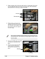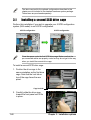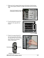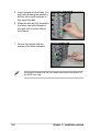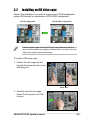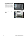
1
AP1720-E1
Dual Intel® Xeon 5U Rackmount Server
533MHz Front Side Bus
User Guide
E1528
Revised edition V2
March 2004
Copyright © 2004 ASUSTeK COMPUTER INC. All Rights Reserved.
No part of this manual, including the products and software described in it, may be
reproduced, transmitted, transcribed, stored in a retrieval system, or translated into any
language in any form or by any means, except documentation kept by the purchaser for
backup purposes, without the express written permission of ASUSTeK COMPUTER INC.
(“ASUS”).
ASUS provides this manual “as is” without warranty of any kind, either express or implied,
including but not limited to the implied warranties or conditions of merchantability or fitness
for a particular purpose. In no event shall ASUS, its directors, officers, employees, or agents
be liable for any indirect, special, incidental, or consequential damages (including damages
for loss of profits, loss of business, loss of use or data, interruption of business and the like),
even if ASUS has been advised of the possibility of such damages arising from any defect or
error in this manual or product.
Specifications and information contained in this manual ae furnished for informational use
only, and are subject to change at any time without notice, and should not be construed as a
commitment by ASUS. ASUS assumes no responsibility or liability for any errors or
inaccuracies that may appear in this manual, including the products and software described
in it.
Product warranty or service will not be extended if: (1) the product is repaired, modified or
altered, unless such repair, modification of alteration is authorized in writing by ASUS; or (2)
the serial number of the product is defaced or missing.
Products and corporate names appearing in this manual may or may not be registered
trademarks or copyrights of their respective companies, and are used only for identification or
explanation and to the owners’ benefit, without intent to infringe.
ii
Contents
Notices ............................................................................................ v
Safety information .......................................................................... vi
About this guide ............................................................................. vii
Chapter 1: Product introduction ......................................... 1-1
1.1
1.2
1.3
1.4
1.5
1.6
System package contents .................................................. 1-2
System specifications ......................................................... 1-3
Front panel features ........................................................... 1-4
Rear panel features ............................................................ 1-5
Internal features ................................................................. 1-6
LED information .................................................................. 1-8
Chapter 2: Hardware setup .................................................. 2-1
2.1
2.2
2.3
2.4
2.5
2.6
2.7
2.8
Chassis cover ..................................................................... 2-2
2.1.1 Removing the side cover ....................................... 2-2
2.1.2 Installing the side cover ......................................... 2-3
Motherboard information .................................................... 2-4
Central Processing Unit (CPU) ........................................... 2-5
2.3.1 Installing a CPU ..................................................... 2-6
2.3.2 Installing the CPU heatsink and fan ....................... 2-7
System memory ............................................................... 2-10
2.4.1 Memory configurations ........................................ 2-10
2.4.2 Installing a DIMM ..................................................2-11
2.4.3 Removing a DIMM ................................................2-11
Front panel assembly ....................................................... 2-12
2.5.1 Removing the front panel assembly .................... 2-12
2.5.2 Re-installing the front panel assembly ................. 2-14
5.25-inch drives ................................................................ 2-15
Hard disk drives ................................................................ 2-18
2.7.1 Installing a hot-swap SCSI HDD .......................... 2-18
2.7.2 Installing an IDE HDD .......................................... 2-20
Expansion cards ............................................................... 2-25
2.8.1 Installing a standard size expansion card ............ 2-25
2.8.2 Installing a long expansion card .......................... 2-27
2.8.3 Removing an expansion card .............................. 2-28
iii
Contents
2.9
Cable connections ............................................................ 2-29
2.9.1 Motherboard connections .................................... 2-29
2.9.2 SCSI backplane connections ............................... 2-30
2.10 Removable components ................................................... 2-36
2.10.1 Chassis fan .......................................................... 2-36
2.10.2 HDD fans ............................................................. 2-37
2.10.3 SCSI backplanes ................................................. 2-39
2.10.4 Power supply module .......................................... 2-41
2.10.5 Floppy disk drive .................................................. 2-44
2.10.6 Front I/O board .................................................... 2-46
2.10.7 Chassis footpads and roller wheels ..................... 2-48
Chapter 3: Installation options ............................................ 3-1
3.1
3.2
3.3
Installing a second SCSI drive cage ................................... 3-2
Installing an IDE drive cage ................................................ 3-5
Mounting the system to a rack ........................................... 3-7
3.3.1 Remove the footpads or roller wheels ................... 3-7
3.3.2 Remove the top cover ............................................ 3-7
3.3.3 Attach the rack rails ............................................... 3-7
Appendix: Power supply ......................................................A-1
A.1 General description ............................................................ A-2
A.2 Specifications ..................................................................... A-3
iv
Notices
Federal Communications Commission Statement
This device complies with Part 15 of the FCC Rules. Operation is subject
to the following two conditions:
• This device may not cause harmful interference, and
• This device must accept any interference received including interference
that may cause undesired operation.
This equipment has been tested and found to comply with the limits for a
Class B digital device, pursuant to Part 15 of the FCC Rules. These limits
are designed to provide reasonable protection against harmful interference
in a residential installation. This equipment generates, uses and can
radiate radio frequency energy and, if not installed and used in
accordance with manufacturer’s instructions, may cause harmful
interference to radio communications. However, there is no guarantee that
interference will not occur in a particular installation. If this equipment does
cause harmful interference to radio or television reception, which can be
determined by turning the equipment off and on, the user is encouraged to
try to correct the interference by one or more of the following measures:
• Reorient or relocate the receiving antenna.
• Increase the separation between the equipment and receiver.
• Connect the equipment to an outlet on a circuit different from that to
which the receiver is connected.
• Consult the dealer or an experienced radio/TV technician for help.
WARNING! The use of shielded cables for connection of the monitor
to the graphics card is required to assure compliance with FCC
regulations. Changes or modifications to this unit not expressly
approved by the party responsible for compliance could void the user’s
authority to operate this equipment.
Canadian Department of Communications Statement
This digital apparatus does not exceed the Class B limits for radio noise
emissions from digital apparatus set out in the Radio Interference
Regulations of the Canadian Department of Communications.
This class B digital apparatus complies with Canadian ICES-003.
v
Safety information
Electrical Safety
•
Before installing or removing signal cables, ensure that the power cables for
the system unit and all attached devices are unplugged.
•
To prevent electrical shock hazard, disconnect the power cable from the
electrical outlet before relocating the system.
•
When adding or removing any additional devices to or from the system, ensure
that the power cables for the devices are unplugged before the signal cables
are connected. If possible, disconnect all power cables from the existing
system before you add a device.
•
If the power supply is broken, do not try to fix it by yourself. Contact a qualified
service technician or your dealer.
Operation Safety
•
Any mechanical operation on this server must be conducted by certified or
experienced engineers.
•
Before operating the server, carefully read all the manuals included with the
server package.
•
Before using the server, make sure all cables are correctly connected and the
power cables are not damaged. If any damage is detected, contact your dealer
as soon as possible.
•
To avoid short circuits, keep paper clips, screws, and staples away from
connectors, slots, sockets and circuitry.
•
Avoid dust, humidity, and temperature extremes. Place the server on a stable
surface.
This product is equipped with a three-wire power cable and plug for the
user’s safety. Use the power cable with a properly grounded electrical
outlet to avoid electrical shock.
Lithium-Ion Battery Warning
CAUTION! Danger of explosion if battery is incorrectly replaced. Replace
only with the same or equivalent type recommended by the manufacturer.
Dispose of used batteries according to the manufacturer’s instructions.
CD-ROM Drive Safety Warning
CLASS 1 LASER PRODUCT
vi
About this guide
Audience
This user guide is intended for system integrators, and experienced users
with at least basic knowledge of configuring a server.
Contents
This guide contains the following parts:
1. Chapter 1: Product Introduction
This chapter describes the general features of the AP1720-E1 server. It
includes sections on front panel and rear panel specifications.
2. Chapter 2: Hardware setup
This chapter lists the hardware setup procedures that you have to
perform when installing or removing system components.
3. Chapter 3: Configuration options
This chapter describes how to install optional components and devices
into the barebone server and create your desired configuration.
4. Appendix: Power supply
This appendix gives information on the power supply that came with
the barebone server.
Conventions
To make sure that you perform certain tasks properly, take note of the
following symbols used throughout this manual.
WARNING: Information to prevent injury to yourself when trying to
complete a task.
CAUTION: Information to prevent damage to the components when
trying to complete a task.
IMPORTANT: Information that you MUST follow to complete a task.
NOTE: Tips and information to aid in completing a task.
vii
References
Refer to the following sources for additional information, and for product
and software updates.
1. ASUS PC-DL Deluxe motherboard user guide
This manual contains detailed information about the PC-DL Deluxe
motherboard.
2. ASUS websites
The ASUS websites worldwide provide updated information for all
ASUS hardware and software products. Refer to the ASUS contact
information.
viii
This chapter describes the general features
of the barebone server. It includes sections
on front panel and rear panel specifications.
ASUS AP1720-E1 user guide
Product introduction
Chapter 1
1-1
1.1
System package contents
Check your ASUS AP1720-E1 package with the items on the following
table. The package contents vary for 8-SCSI, 4-SCSI, and 4-IDE HDD
configurations. Contact your dealer immediately if any of the items is
damaged or missing.
HDD Bays
Item Description
AS8 (8 SCSI ) AS4 (4 SCSI) AI4 (4 IDE)
1) ASUS AK25 5U rackmount chassis with:
• ASUS PC-DL Deluxe motherboard
• 450W power supply
• SCSI backplane board
(2 pieces)
(1 piece)
• ASUS U160/320 SCSI card/SCSI cable
• 52x CD-ROM drive
• floppy disk drive
• chassis fan
• HDD fan
(2 units)
(1 unit)
• hot-swap SCSI HDD trays
(8 units, including screws for HDDs)
(4 units, including screws for HDDs)
• internal HDD rails (4 pairs)
• chassis roller wheels (4 sets)
• CPU heatsink and fan assembly (2 sets)
• front I/O board
• HDD dummy covers (for IDE bays)
2) AC power cable
3) System screws and cables
4) System keys ( 2 pcs.)
5) Bundled CDs
• AP1720-E1 support CD
• ASWM software CD
• TrendMicro® ServerProtect® CD
6) Documentation
• ASUS AP1720-E1 user guide
• ASUS PC-DL Deluxe user guide
7) Optional items
• ASUS AK25 rackmount rail kit
• AK25 internal HDD cage (non-hot swap)
1-2
Chapter 1: Product introduction
1.2
System specifications
The ASUS AP1720-E1 is a barebone server system featuring the ASUS
PC-DL Deluxe motherboard. The server supports dual Intel® Xeon™
processors in 604-pin sockets, and includes the latest technologies
through the chipsets embedded on the motherboard.
Chassis
Pedestal or rackmount 5U with removable front door
bezel and chassis foot stand or roller-wheels.
Motherboard
ASUS PC-DL Deluxe (ATX form factor: 12 in x 9.6 in)
Chipset
Intel® 82875 Memory Controller Hub (MCH)
Intel® 82801ER I/O Controller Hub (ICH5R)
Processor
Supports dual Intel® Xeon™ CPUs up to 3.06+ GHz
with 533MHz FSB
Memory
4 x 184-pin DDR sockets for up to 4GB memory
Supports PC2700/PC2100 unbuffered ECC or
non-ECC DDR DIMMs
LAN
Intel® 82547EI Gigabit LAN controller
IEEE 1394
TI TSB43AB22A IEEE 1394 controller
RAID
Promise® PDC20378 controller
(supports RAID 0/RAID 1/RAID 0+1/Multi-RAID)
Expansion slots
1 x AGP Pro/8X slot
5 x 32-bit/33Mhz 5V PCI slots
Drive bays
1 x 3.25-inch FDD bay
3 x 5.25-inch drive bays
Front I/O
4 x USB 2.0
1 x IEEE 1394 port
Line Out/Microphone ports
Rear panel I/O
1 x Parallel port
2 x Serial ports
1 x RJ-45 port
1 x IEEE 1394 port
4 x USB 2.0 ports
1 x PS/2 keyboard port
1 x PS/2 mouse port
Line In/Line Out/Microphone ports
Management
ASUS Server Web-based Management (ASWM) 2.0
Hardware monitors
Voltage, temperature, and fan speed monitoring
Automatic System Restart (ASR) feature
Power supply
SSI-type 450W power supply (with 24-pin and 8-pin power plugs)
* Refer to the motherboard user guide for more information on internal connectors.
ASUS AP1720-E1 barebone server
1-3
1.3
Front panel features
The AP1720-E1 chassis displays a stylish front bezel with lock. The bezel
covers the system components on the front panel and serves as security.
Open the bezel to access the front panel components.
The drive bays, power and reset
buttons, LED indicators, CD-ROM
drive, floppy drive, and four USB ports
are located on the front panel. For
future installation of 5.25-inch devices,
two drive bays are available.
CD-ROM drive
2 empty 5.25-inch bays
Power button
Reset button
Message LED
HDD access LED
Power LED
Floppy disk drive
IEEE 1394 port
4 USB 2.0 ports
Microphone jack
Line Out jack
Drive bays
Security lock
1-4
Chapter 1: Product introduction
If you wish to access front I/O ports and floppy disk drive without opening
the bezel, hold the tab and move the sliding panel (rightmost panel) to the
left as shown.
1.4
Rear panel features
The rear panel includes a slot for the motherboard rear I/O ports,
expansion slots, a chassis lock and intrusion switch, a vent for the system
fan, and power supply module.
Power supply module
P/S2 mouse port
P/S2 keyboard port
Parallel port
Serial ports
Power connector
12cm fan vent
Chassis lock
IEEE 1394 port
4 USB 2.0 ports
Gigabit LAN port
Audio ports
Expansion slots
SCSI port (optional)
ASUS AP1720-E1 barebone server
1-5
1.5
Internal features
The barebone server system includes the basic components as shown.
AS8 (8-SCSI configuration)
2
1
3
8
10
6
4
7
5
9
1.
2.
3.
4.
5.
Power supply cage
CD-ROM drive
2 x 5.25-inch drive bays
first drive cage (upper)
second drive cage (lower)
6. HDD fan 1
7. HDD fan 2 (optional)
8. Chassis fan
9. Expansion card lock
10. PC-DL Deluxe motherboard
The lower 4-bay hot swap SCSI drive cage may be changed to an
internal IDE drive cage (non-hot swap) if you wish to install long PCI
cards. The internal drive cage is optional and purchased separately.
1-6
Chapter 1: Product introduction
AS4 (4-SCSI configuration)
AI4 (4-IDE configuration)
ASUS AP1720-E1 barebone server
1-7
1.6
LED information
The barebone system comes with five LED indicators. Refer to the
following table for the LED status description.
Power LED (blue)
HDD Access LED (green)
!
Message LED (red)
Drive status LED (green/red)
Drive activity LED
LED
Icon
Display status Description
System
Power LED
ON
Blinking
System power ON
Suspend mode
HDD Access LED
OFF
Blinking
No activity
Read/write data into the HDD
OFF
Blinking
System is normal; no incoming event
ASMS indicates a HW monitor event
Green
Bridge board connected to backplane
Installed HDD is in good condition
HDD failure
HDD rebuilding using the RAID card
SAF-TE* function
Message LED
!
Hard disk drives
Drive Status LED
Red
Red-Blinking
Drive Activity LED
Blinking
Read/write data into the HDD
*SCSI Access Fault-Tolerant Enclosure
The Power, HDD Access, and Message LEDs are visible even if the
system front bezel is closed.
1-8
Chapter 1: Product introduction
Chapter 2
Hardware setup
This chapter lists the hardware setup
procedures that you have to perform when
installing or removing system components.
ASUS AP1720-E1 barebone server
2-1
2.1
Chassis cover
The chassis features a “screwless design” that allows convenient
assembly and disassembly. Simply push or slide mechanical bolts
2.1.1 Removing the side cover
1. Push up the chassis lock (blue
bolt) on the rear panel to release
the side cover.
1
2. Slide the side cover for about half
an inch toward the rear until it is
disengaged from the chassis.
2
2-2
Chapter 2: Hardware setup
Viewing the internal structure
Without the side cover, the internal structure and installed components of
the barebone server vary depending on the model you purchased. Refer
to section “1.5 Internal features” for the different model configurations.
Perform the procedures in the succeeding sections to install the CPU,
system memory, disk drives, and expansion cards; replace fans and power
supply; and connect the system cables.
You may need to remove some of the installed components to access
the DIMM sockets and internal connectors. Refer to section “2.10
Removable components” for instructions.
2.1.2 Installing the side cover
1. Match and insert the hooks of the
cover to the elongated holes on
the side of the chassis. All the six
hooks (three each on the top and
bottom) of the cover must
properly fit the designated holes.
2. Slide the cover toward the front
until it snaps in place.
3. Push down the chassis lock to
secure the side cover.
1
2
3
ASUS AP1720-E1 barebone server
2-3
2.2
Motherboard information
The barebone server comes with the ASUS PC-DL Deluxe motherboard
already installed. The motherboard is secured to the chassis by nine (9)
screws as indicated by circles in the illustration below.
Refer to the motherboard user guide for detailed information on the
motherboard.
This side towards
the rear of the chassis
Make sure to unplug the power cord before installing or removing any
motherboard component or connection. Failure to do so may cause
you physical injury and may damage motherboard components.
2-4
Chapter 2: Hardware setup
2.3
Central Processing Unit (CPU)
The motherboard comes with dual surface mount 604-pin Zero Insertion
Force (ZIF) sockets. The sockets are designed for the Intel® Xeon™
processors in the 604-pin package with 512KB L2 cache.
If installing only one CPU, use CPU socket 1 to ensure system stability.
Socket for CPU1
Socket for CPU2
Before installing the CPU, remove the chassis fan attached to the inner
side of the rear panel to allow enough space for the installation. Refer
to section “2.10 Removable components” for instructions.
ASUS AP1720-E1 barebone server
2-5
2.3.1 Installing a CPU
Follow these steps to install a CPU.
1. Locate the 604-pin CPU1 socket
on the motherboard. Flip up the
socket lever and push it all the
way to the other side.
Make sure that the socket
lever is pushed back all the
way, otherwise the CPU does
not fit in completely.
CPU1 socket
2. Position the CPU above the
socket as shown.
3. Carefully insert the CPU into the
socket until it fits in place.
The CPU fits only in one
correct orientation. DO NOT
force the CPU into the socket
to prevent bending the pins
and damaging the CPU!
Marked corner
4. Carefully push down the socket
lever to secure the CPU. The lever
clicks on the side tab to indicate
that it is locked.
5. Apply the thermal interface
material (thermal grease) to the
top of the CPU. This thermal
grease should come with the CPU
package.
6. Follow steps 1 to 5 if you wish to
install a second CPU.
2-6
Chapter 2: Hardware setup
2.3.2 Installing the CPU heatsink and fan
The system package came with two sets of CPU heatsink and fan
assemblies. Use ONLY the bundled CPU heatsink and fan to ensure
optimum thermal condition and performance.
CPU thermal plate
This motherboard requires a thermal plate for each of the CPUs. The
thermal plates are already installed underneath the motherboard when the
system is shipped.
In case you need to remove and re-install the thermal plates, refer to the
picture below for the correct matching of the motherboard and thermal
plate holes.
Motherboard hole
Standoff
CPU thermal plate
ASUS AP1720-E1 barebone server
2-7
Make sure that you have applied the thermal grease to the top of the
CPU before installing the heatsink and fan!
To install the CPU heatsink and fan:
1. Place the heatsink with fan
assembly on top of the installed
CPU1. Make sure it fits the screw
holes of the heatsink bracket at
the bottom of the CPU socket.
2. Use a Phillips screwdriver to
tighten all four screws enough to
secure the heatsink in place.
Take caution in tightening
screws. Do not over-tighten
screws, doing so may
damage the motherboard!
TIP: Follow the sequence shown:
half-tighten the screw on one
corner of the heatsink and fan,
then the next screw on the other
corner and so on, making a cross
pattern. Repeat until all four
screws are tightened properly.
2
○
○
4
○
○
○
○
○ ○
○ ○
○
○
○
○
○
3
○
1
Make sure heatsink with fan assembly is mounted properly on the CPU
to avoid burning the CPU and/or CPU socket!
2-8
Chapter 2: Hardware setup
3. When the heatsink and fan
assembly is in place, connect the
fan cable plug to the fan
connector on the motherboard
labeled CPUFAN1.
The fan cable plug is slotted
so it fits only in one
orientation. If it doesn’t fit
completely, try reversing it.
4. Make sure that the heatsink and
fan assembly is stable in place
and the fan power cable plug is
properly connected.
Don’t forget to connect the
CPU fan cable plug. Hardware
monitoring errors may occur if
you fail to plug the fan cable.
5. Repeat steps 1 to 2 to install the
heatsink and fan assembly for
the second CPU, then connect
the fan cable to the fan
connector labeled CPUFAN2.
CPUFAN1 cable plug
CPUFAN2 cable plug
ASUS AP1720-E1 barebone server
2-9
2.4
System memory
The motherboard comes with four Double Data Rate (DDR) Dual Inline
Memory Module (DIMM) sockets. These sockets support up to 4GB
system memory using 184-pin unbuffered ECC or non-ECC PC2700/
PC2100 DDR DIMMs, and allow up to 5.33GB/s data transfer rate.
104 Pins
80 Pins
The following figure illustrates the location of the DDR DIMM sockets.
DDR4
DDR3
PC-DL 184-Pin DDR DIMM Sockets
DDR2
DDR1
PC-DL
2.4.1 Memory configurations
Mode
Single-channel
Dual-channel
DIMM_A1
(blue)
(1) Populated
SOCKETS
DIMM_A2
DIMM_B1
(black)
(blue)
DIMM_B2
(black)
—
—
—
(2)
—
Populated
—
—
(3)
—
—
Populated
—
(4)
—
—
—
Populated
—
Populated
—
Populated
—
Populated
Populated
Populated
Populated
(1) Populated
(2)
—
(3)* Populated
* For dual-channel configuration (3), you may:
• install identical DIMMs in all four sockets
or
• install identical DIMM pair in DIMM_A1 and DIMM_B1 (blue sockets)
and identical DIMM pair in DIMM_A2 and DIMM_B2 (black sockets)
2-10
Chapter 2: Hardware setup
2.4.2 Installing a DIMM
Make sure to unplug the power supply before adding or removing
DIMMs or other system components. Failure to do so may cause
damage to both the motherboard and the components.
Follow these steps to install a DIMM.
To access the DIMM sockets, remove the upper HDD fan cage. Refer
to section “2.10 Removable components” for instructions.
DDR DIMM notch
1. Unlock a DIMM socket by
pressing the retaining clips
outward.
2. Align a DIMM on the socket such
that the notch on the DIMM
matches the break on the socket.
Unlocked Retaining Clip
3. Firmly insert the DIMM into the
socket until the retaining clips
snap back in place and the DIMM
is properly seated.
Locked Retaining Clip
2.4.3 Removing a DIMM
Follow these steps to remove a DIMM.
1. While supporting the DIMM with
your fingers, press the retaining
clips outward simultaneously to
release the DIMM from the socket.
2. Remove the DIMM from the
socket.
ASUS AP1720-E1 barebone server
2-11
2.5
Front panel assembly
2.5.1 Removing the front panel assembly
Before you can install a 5.25-inch drive, you should first remove the
front panel assembly (front bezel and front panel cover). The front
panel assembly is attached to the chassis through four hooked tabs
on the left side and four hinge-like tabs on the right side.
To remove the front panel assembly:
1. Press the lock lever (blue bar) on the
front edge of the chassis to release the
front panel assembly.
Lock lever
2. Pull and swing the left edge of the front
panel outward.
2-12
Chapter 2: Hardware setup
3. Unhook the hinge-like tabs from the holes on the right side of the front
panel to completely detach the front panel assembly from the chassis.
Do not use too much force when removing the front panel assembly.
Hinge-like tab
ASUS AP1720-E1 barebone server
2-13
2.5.2 Re-installing the front panel assembly
To re-install the front panel assembly (front bezel and front panel cover):
1. Insert the four hinge-like tabs to the holes on the right edge of the
chassis.
2. Swing the front panel to the left and fit the four (4) hooked tabs to the
left side of the chassis until the tabs snap back in place.
1
Hinge-like tab
2
Hooked tab
2-14
Chapter 2: Hardware setup
2.6
5.25-inch drives
If you have previously used and powered up the system, and that it
may be connected to an AC power source, make sure to unplug the
power cable before installing or removing any system components.
Failure to do so may cause damage to the motherboard and other
system components!
Three 5.25-inch drive bays are
located on the upper front part of the
chassis. A CD-ROM drive that comes
standard with the system package
occupies the uppermost bay (labeled
1). The two lower bays (labeled 2 and
3) are available for additional
5.25-inch devices.
1
2
3
To install a 5.25-inch drive:
1. Use a Phillips (cross) screwdriver
to remove the screws that secure
the metal cover of the bay where
you wish to install the drive.
2. From the side of the drive bay,
slide the drive bay lock by
pushing it to the left to release the
drive lock bar.
Drive lock bar
Drive bay lock
ASUS AP1720-E1 barebone server
2-15
3. When released, pull up the drive bay lock bar. Underneath the lock bar
are two pegs that match the holes on the drive bay. This mechanism
secures the drive to the bay in place of screws.
Lock pegs
Drive bay holes
4. While holding up the bar lock,
carefully insert a 5.25-inch drive
into the bay, until the back of the
drive aligns to the rear edge of
the drive cage.
Due to space constraints inside the chassis, do not insert the drive all
the way at this time. This will allow you enough space to easily connect
the drive cables.
5. Connect the IDE cable to the IDE
connector on the back of the
drive.
6. Connect a 4-pin plug from the
power supply to the power
connector on the back of the
drive.
IDE cable
Power plug
2-16
Chapter 2: Hardware setup
7. Make sure that the drive and bay
holes align as shown. When in
place, the drive protrudes about
an inch from the front panel.
8. Pull down the bar lock and insert the
lock pegs to the drive/bay holes,
then push the drive lock to the right
to secure the drive.
9. On the front panel assembly, detach the plastic bay cover opposite the
5.25-inch drive that you installed by pressing the two hooked tabs on
each side of the bay cover.
Bay cover tabs
10. Re-install the front panel assembly when done. Refer to section “2.5.2
Re-installing the front panel assembly” for instructions.
ASUS AP1720-E1 barebone server
2-17
2.7
Hard disk drives
2.7.1 Installing a hot-swap SCSI HDD
To install a SCSI hard disk drive:
1. Open the front bezel to access
the hot-swap drive trays.
2. Release a drive tray by pushing
the spring lock to the right, then
pulling the tray lever outward.
The drive tray ejects slightly after
you pull out the lever.
Spring lock
Tray lever
3. Firmly hold the tray lever and pull
the drive tray out of the bay.
4. An empty drive tray requires a metal bracket for support. Use a Phillips
(cross) screwdriver to remove the bracket if you wish to install a hard
disk in the drive tray.
Metal bracket
2-18
Chapter 2: Hardware setup
5. Place an SCA SCSI hard disk into
the drive tray, and secure it with
four screws.
6. Carefully insert drive tray and
push it all the way to the depth of
the bay until just a small fraction
of the tray edge protrudes.
7. Push the tray lever until it clicks,
and secures the drive tray in
place. The drive tray is correctly
placed when its front edge aligns
with the bay edge.
ASUS AP1720-E1 barebone server
2-19
2.7.2 Installing an IDE HDD
If your system is an IDE model, your package comes with specially
designed hard disk drive rails. Depending on which bay you wish to install
your hard disk drive, the orientation of the drive rails vary so that the screw
holes match those on the drive.
For identification purposes, the drive rails will be referred to as “Rail 1”
and “Rail 2” as shown below.
Rail 1
Rail handle
Hole 1
Hole 2 Hole 3
Hole 4
Rail 2
Take note of the correct orientation of the drive rails. There is only one
correct way to attach the rails when installing drives on the first and
second drive cages.
Installing into a bay on the first drive cage
To install a drive from the front panel opening:
1. Remove the front panel assembly. Refer to section 2.5.1 for
instructions.
2. Use a Phillips (cross) screwdriver to attach Rail 1 to the side of the
drive as shown. The rail end should be on the side of the drive
connectors.
Hole 1
Hole 3
Rail end
Drive connectors
2-20
Chapter 2: Hardware setup
3. Attach Rail 2 to the other side of the drive as shown. The rail end
should be on the side of the drive connectors.
Hole 3
Hole 1
Rail end
Drive connectors
4. Check the HDD jumper setting. Refer to the label pasted on the HDD
for the setting description. The setting “Cable Select” is recommended.
5. Carefully insert the drive into a
bay on the front panel.
6. Push the drive all the way to the
depth of the bay until the rail locks
clicks, indicating that the drive is
securely in place.
ASUS AP1720-E1 barebone server
2-21
7. Connect the IDE and power
cables to their corresponding
connectors on the back of the
drive.
8. Follow steps 2 to 6 if you wish to
install other hard disk drives.
9. Re-install the front panel
assembly when done.
Installing into a bay on the second drive cage
To install an internal drive :
1. Remove the side cover. Refer to section 2.1.1 for instructions.
2. Use a Phillips (cross) screwdriver to attach Rail 2 to the side of the
drive with two screws as shown. The rail handle should be on the side
of the drive connectors.
Rail handle
Drive connectors
Hole 4
Hole 2
3. Attach Rail 1 to the side of the drive with two screws as shown. The
rail handle should be on the side of the drive connectors.
Hole 2
Hole 4
Rail handle
Drive connectors
2-22
Chapter 2: Hardware setup
4. Check the HDD jumper setting. Refer to the label pasted on the HDD
for the setting description. The setting “Cable Select” is recommended.
5. Carefully insert the drive into a
bay on the second drive cage as
shown.
6. Connect the IDE and power
cables to their corresponding
connectors on the back of the
drive.
7. Follow steps 2 to 5 if you wish to install other hard disk drives.
8. Re-install the side cover when done. Refer to section “21.2 Installing
the side cover.”
ASUS AP1720-E1 barebone server
2-23
Installing an HDD dummy cover
Except on the 8-SCSI configuration model (AS8), the HDD dummy covers
come pre-installed on the front panel bezel. In case you removed the
covers, follow these steps to re-install them.
To install an HDD dummy cover:
1. From the inside of the front panel
assembly, insert the flat end of a
dummy cover into the slot as shown.
The end with the hook tab should be
close to the front panel LEDs.
Flat end
Hook tab
2. Press the dummy cover into the slot
opening until the hook tab clicks in
place.
3. When installed, the dummy cover
appears as shown.
2-24
Chapter 2: Hardware setup
2.8
Expansion cards
The chassis is designed with a screwless expansion slot frame on the rear
panel. This design feature allows you to install or remove an expansion
card in less steps.
Make sure to unplug the power cord before installing or removing
expansion cards. Failure to do so may cause physical injury, and
damage to the card and motheboard components!
2.8.1 Installing a standard size expansion card
To install a standard size expansion card:
1. Remove the plastic card lock opposite the slot where you wish to install
the expansion card. Release the card lock by pressing the center tabs
and pushing outward. Set the card lock aside for later use.
Card lock tabs
2. Carefully install an expansion
card making sure that it is
properly seated on the slot.
ASUS AP1720-E1 barebone server
2-25
3. When the card is in place, secure
it with the plastic card lock that
you removed earlier.
Card lock tab
2-26
Chapter 2: Hardware setup
2.8.2 Installing a long expansion card
If you wish to install a long expansion card, such as some types of RAID
cards, you need to remove the lower hot swap drive cage and install an
internal (non-hot swap) drive cage with long card guides that keep the
expansion cards firmly seated on the slots.
1. The internal drive cage is optional and separately purchased. See
section “Chapter 3 Optional components” for instructions on
installing the drive cage.
2. The AS4 (4-SCSI configuration) and AI4 (4-IDE configuration)
models support long expansion cards.
To install a long expansion card:
1. Remove the plastic card lock opposite the slot where you wish to install
the expansion card. Release the card lock by pressing the center tabs
and pushing outward. Set the card lock aside for later use.
2. Tilt the long card as shown while
aligning the metal bracket with the
slot opening on the rear panel.
3. When the card is inside the
chassis, push down the end of the
card until it is level with the PCI
slot.
ASUS AP1720-E1 barebone server
2-27
4. Push the card connector into the
PCI slot until it is securely seated.
5. When the card is in place, secure
it with the plastic card lock that
you removed earlier.
2.8.3 Removing an expansion card
To remove an expansion card:
1. Remove the plastic card lock that secures the expansion card.
Card lock tabs
2. Firmly hold the expansion card
and pull it out of the slot.
3. Place the plastic card lock back where you removed it.
2-28
Chapter 2: Hardware setup
2.9
Cable connections
The bundled system cables are pre-connected before shipment. You
do not need to disconnect these cables unless you will remove preinstalled components to install additional devices.
Refer to this section when reconnecting cables to ensure correct cable
connections.
2.9.1 Motherboard connections
2
1
3
4
10
8
5
6
7
9
11
12
Standard cables connected to the motherboard
1.
2.
3.
4.
5.
6.
24-pin ATX power
8-pin 12V AUX power
Front panel audio
HDD fan 2
HDD fan 1
Front panel USB (4 ports)
7.
8.
9.
10.
11.
12.
Front panel 1394
Chassis intrusion
Front panel LEDs
Secondary IDE (optical drive)
SMBus panel to backplane
Floppy disk
Refer to the motherboard user guide for detailed information on the
connectors.
ASUS AP1720-E1 barebone server
2-29
2.9.2 SCSI backplane connections
The SCSI backplane has four 68-pin SCSI connectors to support SCA
SCSI hard disks. The backplane design incorporates a hot swap feature to
allow easy connection or removal of SCSI hard disks. The LEDs on the
backplane connect to the front panel LEDs to indicate HDD access, HDD
failure, thermal failure, or fan failure. See section “1.6 LED information.”
Front side
The front side of the SCSI backplane faces the front panel when installed.
This side includes four SCSI connectors for the hot swap drive trays.
First backplane
HDD status LEDs
Disk drive 1
SCSI ID = 0
Disk drive 2
SCSI ID = 1
HDD activity LEDs
Disk drive 3
SCSI ID = 2
Disk drive 4
SCSI ID = 3
If your barebone server supports a hot swap configuration for eight (8)
hard disks, a second SCSI backplane comes with the system to connect
drives 5 to 8.
Second backplane
HDD status LEDs
Disk drive 5
SCSI ID = 4
Disk drive 6
SCSI ID = 5
HDD activity LEDs
Disk drive 7
SCSI ID = 6
Disk drive 8
SCSI ID = 8
SCSI ID7 is reserved for the SCSI card.
2-30
Chapter 2: Hardware setup
Back side
The back side of SCSI backplane faces the rear panel when installed. This
side includes the power connectors, SCSI interfaces for the SCSI/RAID
card and terminator, and SMBus connectors.
The following picture shows a two-backplane configuration in a cascade
connection.
First SCSI backplane
Cascade connection
SCSI terminator
Second SCSI backplane
ASUS AP1720-E1 barebone server
2-31
One-backplane configuration
In a one-backplane configuration:
•
•
the upper SCSI interface of the backplane connects to the SCSI/RAID
card
a SCSI multi-mode terminator (LVD/SE) is connected to the lower SCSI
interface of the backplane
Power connectors
(connect power plugs
from the power supply)
Fan connector (for HDD fan)
SMBus connector (upper 6-1 pins)
68-pin SCSI connector
(connects the SCSI cable
from the SCSI/RAID card)
2-32
(connects the SMB cable from the
motherboard)
68-pin SCSI connector
(with SCSI multi-mode terminator)
Chapter 2: Hardware setup
Two-backplane configuration
In a two-backplane configuration:
•
•
•
the upper SCSI interface of the first backplane connects to the SCSI card
the lower SCSI interface connects to the upper SCSI interface of the
second backplane
a SCSI multi-mode terminator (LVD/SE) is placed on the lower SCSI
interface of the second backplane
First backplane
Power connectors
(connect power plugs
from the power supply)
Fan connector (for HDD fan)
SMBus connector (upper 6-1 pins)
(connects the SMB cable from the
motherboard)
SMBus connector (lower 6-1 pins)
(connects the SMB cable to the second
backplane)
68-pin SCSI connector
(connects the SCSI cable
from the SCSI card)
68-pin SCSI connector
(connects the SCSI cable to
the second backplane)
Second backplane
SMBus connector (upper 6-1 pins)
(connects the SMB cable from the first
backplane)
68-pin SCSI connector
(connects the SCSI cable from
the first backplane)
68-pin SCSI connector
(with SCSI multi-mode terminator)
ASUS AP1720-E1 barebone server
2-33
SCSI backplane jumper settings and HDD ID assignments
The 6-pin jumper J1 on each of the SCSI backplanes allows you to define
your desired SCSI configuration.
The picture below shows the location of jumper J1 with pins 1-3 and 2-4
shorted.
Refer to the following tables for the jumper settings and the appropriate
ID# for each SCSI HDD bay.
Cascade configuration
First backplane (BPB1)
J1 setting (1-3 shorted, 2-4 shorted)
Device
SCSI ID#
Drive Bay 1
ID0
Drive Bay 2
ID1
Drive Bay 3
ID2
Drive Bay 4
ID3
GEM SAF-TE
ID15
Second backplane (BPB2)
J1 setting (3-5 shorted, 4-6 shorted)
2-34
Device
SCSI ID#
Drive Bay 5
ID4
Drive Bay 6
ID5
Drive Bay 7
ID6
Drive Bay 8
ID8
GEM SAF-TE
ID11
Chapter 2: Hardware setup
Non-Cascade configuration
First backplane (BPB1)
J1 setting (1-3 shorted, 2-4 shorted)
Device
SCSI ID#
Drive Bay 1
ID0
Drive Bay 2
ID1
Drive Bay 3
ID2
Drive Bay 4
ID3
GEM SAF-TE
ID15 (SCSI channel-0)
Second backplane (BPB2)
J1 setting (1-3 shorted, 2-4 shorted)
Device
SCSI ID#
Drive Bay 5
ID0
Drive Bay 6
ID1
Drive Bay 7
ID2
Drive Bay 8
ID3
GEM SAF-TE
ID15 (SCSI channel-1)
SCSI ID7 is reserved for the SCSI card.
ASUS AP1720-E1 barebone server
2-35
2.10 Removable components
You may need to remove previously installed system components when
installing or removing system devices, or when you need to replace
defective components. This section tells how to remove the following
components:
1. Chassis fan
2. HDD fans
3. SCSI backplanes
4. Power supply module
5. Floppy disk drive
6. Front I/O board
2.10.1 Chassis fan
To remove the chassis fan:
1. Disconnect the 3-pin fan cable
from the connector CHA_FAN1
on the motherboard.
2. Press the tabs on the outer
corners of the system fan, then
pull the fan out of the chassis.
To re-install the chassis fan:
1. Firmly hold the chassis fan on the
side with the tabs and position it
into its slot, making sure that the
four hooks underneath the fan
match the corresponding holes on
the rear panel.
2. Push the fan into the chassis until
the four hooks lock securely into
the holes on the rear panel.
3. Re-connect the 3-pin fan cable
from the connector CHA_FAN1 on the motherboard.
2-36
Chapter 2: Hardware setup
2.10.2 HDD fans
To remove the HDD fan:
1. Loosen the thumb screw that
secures the HDD fan cage to the
chassis.
2. Hold the outer side of the fan
cage, then pull sideways to
release it from the chassis.
3. Disconnect the 3-pin fan cable
from the fan connector on the
backplane before completely
detaching the fan cage from the
chassis.
Due to space constraints inside the chassis, some cables may interfere
with the removal of the fan cage. To easily remove the fan cage, try to
slightly push it inward (toward the motherboard) before pulling it out of
the chassis.
ASUS AP1720-E1 barebone server
2-37
To re-install the HDD fan:
1. Re-connect the 3-pin fan cable to the fan
connector on the backplane.
Fan connector on
backplane (FAN1)
2. Hold the outer side of the HDD fan cage and hook the two side tabs to
the inner edge of the drive cage. Make sure that the system cables are
not caught up when you place the HDD fan.
Outer side of fan cage
Side tabs
Inner edge of drive cage
3. Push the outer edge of the fan
cage sideways to fit it to the drive
cage. You hear a click when the
fan cage correctly fits in place.
4. Secure the fan cage with the
thumb screw.
2-38
Chapter 2: Hardware setup
2.10.3 SCSI backplanes
To remove a SCSI backplane:
1. Remove the HDD fan cage. Refer to section “2.10.2 HDD fans” for
instructions.
2. Disconnect all cables from the
backplane.
When disconnecting a cable, hold and firmly pull the cable plug. DO
NOT pull the cable itself. Doing so may damage the cable!
3. From the inner edge, push the
backplane outward so that the
outer edge protrudes slightly
from the slot.
4. From the outer edge, firmly hold
the backplane and carefully
slide it out.
ASUS AP1720-E1 barebone server
2-39
To re-install a SCSI backplane:
1. Position the backplane into its slot
with the component side facing
the rear panel, and the power
connectors on top.
2. Align the backplane with the raillike dents on the slot to ensure
that it fits securely.
Rail-like dents
3. Slide the backplane into the slot
until it fits. If correctly installed,
the outer edge of the backplane
aligns with the corner of the drive
cage.
4. Connect the appropriate cables to
the backplane. Refer to section
“2.9.2 SCSI backplane
connections” for information on
backplane cabling.
2-40
Chapter 2: Hardware setup
2.10.4 Power supply module
You MUST disconnect all power cable plugs from the motherboard and
other installed devices before removing the power supply.
The picture below shows the motherboard and device connectors where
the power plugs are connected. Refer also to Appendix at the end of this
document for details on the power supply.
3
2
1
4
6
5
1
2
3
4
5
6
24-pin ATX (motherboard power connector)
8-pin +12V AUX (motherboard power connector)
4-pin plug (optical drive)
2 x 4-pin plugs (first backplane, if present)
2 x 4-pin plugs (second backplane, if present)
4-pin plug (floppy disk drive)
ASUS AP1720-E1 barebone server
2-41
Make sure to unplug ALL power cables from the system devices
before removing the power supply module.
To remove the power supply module:
1. Loosen the thumbscrew that
secures the power supply metal
plate. Do not remove the thumb
screw from the metal plate.
Thumbscrew
2. Hold the metal plate bar and push
it downward to release the plate
from the chassis. Remove the
metal plate completely.
Metal plate bar
3. Use one hand to push the power
supply module from inside the
power supply cage, then carefully
pull out the module from the
chassis.
2-42
Chapter 2: Hardware setup
To install a power supply module:
1. Firmly hold the power supply
module and insert it into the
power supply cage.
2. Push the power supply all the way
in until its outer end aligns with
the rear panel.
Be careful with the power supply cables when inserting the power
supply module into the cage. Due to space constraints, the cables may
get entangled with the installed components or other cables, causing
the cables to break!
3. Place the metal plate flat on the
outer end of the power supply
module, flushed to the top of the
chassis, while matching the four
hooks with their corresponding
holes on the rear panel.
Hook matched to a hole
4. Hold the metal plate bar and push
it upward to lock the hooks to
their holes. At the same time, you
may also push the top of the
metal plate to fit it completely.
5. Secure the metal plate with the
thumb screw.
ASUS AP1720-E1 barebone server
2-43
2.10.5 Floppy disk drive
You need to remove the front panel assembly before you can remove
the floppy disk drive. Refer to section “2.5.1 Removing the front panel
assembly” for instructions.
To remove the floppy disk drive:
1. Remove the screw that secures
the drive to the chassis.
2. Carefully pull out the drive from
the chassis until you see the
cables connected to the drive.
3. Disconnect the floppy disk cable
and power cable from the drive to
completely release the drive.
2-44
Chapter 2: Hardware setup
To install a floppy disk drive:
1. Position the floppy drive vertically
with the eject button on the left
side (close to the HDDs).
2. Connect the drive signal cable
and power cable.
Eject button
Floppy drive
power cable
Red stripe to match
Pin 1 on the connector
Floppy drive
signal cable
3. Carefully push the drive into the
bay until the drive cage fits the
front edge of the bay.
4. Secure the drive cage with a
screw.
ASUS AP1720-E1 barebone server
2-45
2.10.6 Front I/O board
You need to remove the front panel assembly before you can remove
the front I/O board. Refer to section “2.5.1 Removing the front panel
assembly” for instructions.
To remove the front I/O board:
1. Remove the screw that secures
the front I/O board bracket to the
front panel.
2. Carefully pull out the bracket until
you see the cables connected to
the I/O board.
3. Disconnect all the cables from the
I/O board.
4. Remove the screw that secures
the I/O board to the bracket.
2-46
Chapter 2: Hardware setup
To install the front I/O board:
1. Place the I/O board in the
bracket, component side up.
Secure the front I/O board to the
bracket with a screw.
2. Position the I/O board into the bay
with the component side to the
left (close to the HDDs). Connect
the I/O cables to the connectors
on the back of the I/O board.
Audio connector (black)
USB 2.0 connectors (blue)
1394 connector (red)
3. Insert the I/O board into the bay
until the bracket fits the front
edge of the bay.
4. Secure the I/O board bracket with
a screw.
ASUS AP1720-E1 barebone server
2-47
2.10.7 Chassis footpads and roller wheels
The barebone server system is shipped with four footpads attached to the
bottom of the chassis for stability. You need to remove these footpads if:
•
•
if you want to replace the footpads with the bundled roller wheels
you wish to install the system to a rack
(Refer to “Chapter 3 Installation options” of this user guide, and to the
“Rackmount Kit” user guide for instructions)
To remove the footpads:
1. Lay the system chassis on its
side.
2. Use a flat screwdriver to flip out
the top layer of a footpad.
3. Remove the footpad by rotating it
counterclockwise.
4. Repeat steps 2 and 3 to remove the other three footpads.
2-48
Chapter 2: Hardware setup
For convenient transport, install the roller wheels the came with the system
package. Each wheel has a brake lock to stabilize the chassis in place.
To install the chassis wheels:
1. Lay the chassis in its side.
2. Locate the designated screw
holes for each of the four wheel
sets. Take note of the numbers
alongside each hole when placing
screws.
3
1
2
4
3. Secure each wheel to the bottom
of the chassis using four screws.
4. Repeat steps 2 and 3 to install the
other three wheels.
Remove the chassis roller wheels if you wish to mount the system to a
rack.
To remove the chassis wheels:
1. Lay the system chassis on its
side.
2. Use a Phillips screwdriver to
remove the screws that secure
the wheels to the bottom of the
chassis.
3. Repeat step 2 to remove the
other three roller wheels.
ASUS AP1720-E1 barebone server
2-49
2-50
Chapter 2: Hardware setup
This chapter describes how to install
optional components and devices into the
barebone server and create your desired
configuration.
ASUS AP1720-E1 barebone server
Installation options
Chapter 3
3-1
The items required for the optional configurations described in this
chapter are not included in the standard barebone system package.
These items are purchased separately.
3.1
Installing a second SCSI drive cage
Perform this installation if you wish to upgrade your 4-SCSI configuration
system (AS4 model) to an 8-SCSI configuration.
4-SCSI configuration
8-SCSI configuration
Clear the space under the first SCSI drive cage. Make sure that the
pre-connected cables are properly routed so they do not get in the way
when you install the second drive cage.
To install a second SCSI drive cage:
1. Position the drive cage in the
same orientation as the first drive
cage. Note that the lock tab on
top of the cage faces the rear
panel.
Cage lock tab
2. Carefully slide the drive cage
toward the front panel until it fits
in place.
3-2
Chapter 3: Installation options
3. Make sure that the cage lock tab snaps to the bottom of the first drive
cage. When properly installed, the cage should align with the first drive
cage.
Cage lock tab snapped securely
to the bottom of first drive cage
4. From the front side, secure the
right side of the cage with two
screws.
Front screw holes
5. Position the support bracket for
the drive trays to the left side of
the cage with the three protruding
tabs matching the elongated
holes on the chassis.
Protruding tabs
Screw holes
Elongated holes for bracket
SCSI drive tray support bracket
ASUS AP1720-E1 barebone server
3-3
5. Insert the tabs into the holes. You
may need to swing the bracket a
bit from left to right and back to
fully insert the tabs.
6. When the tabs are fully inserted in
the holes, swing the bracket to
the right until one side is flat to
the chassis.
7. Secure the bracket with two
screws in the holes indicated.
Securing the bracket with the two screws also secures the left side of
the SCSI drive cage.
3-4
Chapter 3: Installation options
3.2
Installing an IDE drive cage
Perform this installation if you wish to upgrade your 4-SCSI configuration
system (AS4 model) to a combination 4-SCSI/4-IDE configuration.
4-SCSI configuration
4-SCSI/4-IDE configuration
Clear the space under the first SCSI drive cage. Make sure that the
pre-connected cables are properly routed so they do not get in the way
when you install the second drive cage.
To install an IDE drive cage:
1. Position the drive cage into the
bay with the screw hole tab on top
and facing out.
Screw hole
2. Carefully slide the drive cage
toward the front panel until it fits
in place.
ASUS AP1720-E1 barebone server
3-5
3. Make sure that the drive cage is
fits snugly to the bay as shown.
The drive cage is properly
installed when it is parallel to the
front panel, and the screw hole
matches the hole of the first drive
cage.
Screw hole
4. Secure the drive cage with a
screw.
3-6
Chapter 3: Installation options
3.3
Mounting the system to a rack
3.3.1 Remove the footpads or roller wheels
Refer to section “2.10.7 Chassis roller wheels and footpads” for
instructions on removing the footpads or roller wheels.
3.3.2 Remove the top cover
To remove the top cover:
1. Remove the side cover. Refer to section “2.1.1 Removing the side
cover” for instructions.
2. Remove the front panel assembly. Refer to section “2.5.1 Removing
the front panel assembly” for instructions.
3. Locate the lock tab underneath
the top cover and press it outward
to release the cover.
4. Slide the top cover toward the
front panel, then lift it up from the
chassis.
Lock tab of top cover
(bottom view)
3.3.3 Attach the rack rails
Refer to the installation guide that came with the Rackmount Rail Kit for
instructions on how to attach the rails and on the barebone server system
and the corresponding rails on the industrial rack.
ASUS AP1720-E1 barebone server
3-7
3-8
Chapter 3: Installation options
Appendix
Power supply
This appendix gives information on the
power supply that came with the barebone
server.
ASUS AP1720-E1 barebone server
3-1
A.1
General description
The server comes with an SSI-type 450W ATX power supply with universal
AC input that includes PFC and ATX-compliant output cables and
connectors. The power supply has nine plugs labeled P1 to P10 (no P3).
Take note of the devices to which you should connect the plugs.
P1
P1
P2
P4
P5
P6
P7
P8
P9
P10
A-2
P2
P4
P5
P6
P7
P8
P9
P10
Motherboard 24-pin ATX power connector
Motherboard 8-pin +12V AUX power connector
Floppy disk drive
Peripheral device (second backplane, if present)
Peripheral device (available)
Peripheral device (second backplane, if present)
Peripheral device (first backplane, if present)
Peripheral device (first backplane, if present)
Peripheral device (optical drive)
Chapter 3: Installation options
A.2
Specifications
Output voltage regulation
Output Voltage
Min (V)
Nom (V)
Max (V)
+3.33V
3.16
3.30
3.46
50mVp-p
4.8
5.00
5.25
50mVp-p
+12V
11.52
12.00
12.60
120mVp-p
-12V
-11.4
-12.20
-13.08
120mVp-p
4.8
5.00
5.25
50mVp-p
+5V
+5VSB
Ripple/Noise
Output current capacity
Output Voltage
Min (A)
Max (A)
Max. Load (W)
+3.33V
0.5
24.0
79.0
+5V
2.0
20.0
100.0
+12V
4.0
30.0
360.0
-12V
0.0
0.5
6.0
+5VSB
0.1
2.0
10
Over-voltage protection
Voltage
Min (V)
+3.33V
3.9
4.5
+5V
5.7
6.5
+12V
13.3
15.0
+12V
-13.3
-15.0
5.7
6.5
+5VSB
Max (V)
ASUS AP1720-E1 barebone server
A-3
A-4
Chapter 3: Installation options