1
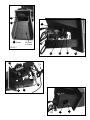
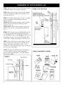
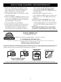
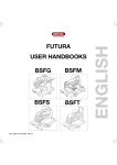
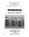
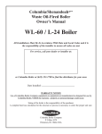
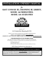
INSTALLATION /OWNER’S MANUAL
for
KAST CONSOLE III, CHANNING III, LIBERTY,
MODEL 140 PADDLE FEED,
MODEL 140 AUGER FEED
STOVE COMPANY
STOVE
COMPANY
Established 1977
3162 Columbia Blvd., Bloomsburg PA 17815
TURN TO LAST PAGE IN MANUAL FOR CLEARANCE SPECIFICATIONS!
MODEL 140 AUGER FEED CAN BURN COAL OR PELLETS
CHANNING III, CAST CONSOLE III, LIBERTY, MODEL 140 (STANDARD FEED) ARE FOR COAL ONLY
UNDERSTANDING YOUR STOKER STOVE
Your Stoker Stove operates utilizing “continuous air” with a time feed mechanism.
The advantage of a constant air feed system over any thermostat type operations are:
1) A longer burning season.
2) Your fuel burns better.
3) The auto heat control box allows you to increase and decrease fire size.
NOTE: Chimney should match stove exhaust pipe size.
CAUTION:
STOVE DOORS MUST REMAIN CLOSED AT ALL TIMES WHILE STOVE IS IN OPERATION.
Entire vent system should be cleaned at least ONCE PER MONTH. Fossil fuel burning can create lethal
doses of carbon monoxide gas. This gas has no odor or color. Purchase a carbon monoxide alarm for
detection. Have your chimney cleaned professionally before burning any coal stove.
5/06
FEEDER ASSEMBLY
Locate unit (See Fig. 1 on page 3 and Fig. 2 on page 2).
Check that strongback gasket is positioned properly as
shown in Fig 1. The strongback gasket position is critical
in that it prevents air escape to the hopper area which
could result in “hopper fire” or warpage to the overplate.
The cast iron grate should sit snug to the housing. The
gear motor moves the feed bar in a paddle like fashion,
to push the coal across the grate. A separate motor with a
plastic fan blows air through the grate for the combustion
process. Wiring should be connected as shown below.
FEEDER ASSEMBLY
PARTS LIST
1. Auto Heat Control Box
2. Feeder Housing
3. Grate
4. Half Moon Feed Paddle
5. Plastic Wheel (Combustion Wheel)
6. Airmotor Tray
7. Cover Plate Bolt 1/4" x #20 x 2"
8. (4) #10/32 Nuts
9. Ball Joint Feed Arm
10. Feed Motor
11. Feed Motor Block
12. 1/2 Moon Feed Block
13. (2) 1/4" x #20 Wing Nuts
14. Strongback Gasket
15. Removable Feed Motor Tray
16. Airmotor / Combustion Motor
17. Grate Gasket 2' X Channel Gasket
18. Triple Plug Adapter
19. Paddle Plate (Note: 2 screws w/nut
3/8" x flat head not shown)
20. (2) 1/4" x #20 x 1" cap screws
21. Grease Fitting
22. 4' x 3/8" Rope Gasket
WIRING: Locate plug connections below, connect
the male and female plugs with matching letters
(example A.M. to A.F.) connect C.M. to a 110 volt
wall outlet.
NOTE: Your feeder unit should come to you fully
assembled and ready to plug in.
RHEOSTAT - is used to control the speed of your air
distribution fan and allows you the air push you desire.
NOTE: Strongback is gray in color. make sure it’s
pinched between the grate and the feeder housing.
As shown below. IMPORTANT: Paddle should be
greased at least twice per year with standard grease
(see grease fitting position below). Grate gasket should
be applied to feeder housing.
Hopper
Gasket
4
22
19
B.M.
B.F.
10
2
C.M.
1
FIGURE 2
2
14
17
21
3 Grate
Air Holes
In Grate
16
FIGURE 1
6
15
12
20
2
CM
AF
8
18
9
11
AM
3
5
7
PADDLE FEED
ADJUSTING THE FIRE SIZE - The Auto Heat Box is
your fire size control. The box is numbered 1 to 5.
Generally a setting of 1 will maintain a minimum fire.
A setting of approximately 5 will give you a full
efficient fire (85,000 BTUs). A setting of less than 1 may
cause your fire to go out. A setting of over 5 may cause
hot burning coals to spill off the grate before it is fully
burned. Select a setting between the low burn of 1 and
the high burn of 5 until your home is comfortable.
Allow ample time for fire to adjust. A maximum fire
should not exceed and inch of ash on the end of the grate.
AUGER FEED
Auto heat box for the Auger Feed may be adjusted higher
than the 5 setting to achieve a full fire.
Read this page before installing your stove.
READ ENTIRE MANUAL
• Masonry or factory built class “A” chimney may be
used. A height of at least 15' from floor to top of
chimney with an inside opening of a least 6" is required.
• This Stoker can also be installed using our “Alaska
Vent” system. Ask your dealer for details.
• Make sure your chimney is free of any obstructions.
The clean out door should be sealed and securely
attached. Have your chimney cleaned and inspected
before starting your stove.
• Be sure to purchase and install a carbon monoxide
detector before you start to burn your stove.
• Contact your local building code officer, or your fire
safety inspector to insure you’re in compliance with
local codes as they can vary.
• Alaska Company recommends that you install your
stove with a Barometric Damper. We also recommend
a minimum draft of .04" of water column, although
this stove may draft at lower measurements. It may not
function properly, by following these requirements it
will help regulate your draft in high wind conditions
and allow your stove to burn more efficiently.
• Fresh air is important to the function of your stove, an
over insulated (air tight) house may not allow enough
combustion air for the proper performance of your
stove. This can be corrected by slightly opening a
window or installing a fresh air inlet.
• Glass Cleaning and Care - Stove glass is high temp
ceramic which can be fragile. Do not use cold water to
clean. Do not slam door shut as fracturing could occur.
Abrasive cleaners will scratch the glass. Do not clean
glass while hot. Use a ceramic glass cleaner and soft
cloth.
• Brass and Gold Plating Care - Be sure to clean all
fingerprints and oils from these surfaces before lighting
your stove. Do not use an abrasive cleaner. Denature
alcohol and a soft cloth are suggested. Any other
cleaning products should be used according to the
manufacturer’s instruction.
CAUTION: If you are installing your Stoker Stove in a
basement and your home uses a “heat pump” system,
return air must be provided to the basement area.
EXAMPLE: Do not pull air out of the basement with
provision for return air or you could reverse the chimney
draft of the stoker causing sulfur dioxide and carbon
monoxide to enter living area.
ASSEMBLY OF TOP VENT KAST CONSOLE III, CHANNING III
NOTE: Most stoves are preassembled.
STEP 1 Remove all parts from box and stove body.
Locate feeder plate (See Fig. 3). Remove the 4 bolts from
the feeder plate. Align the feeder assembly with the holes
in the feeder plate. Insert the 4 bolts and tighten.
follows: Place a washer over bolt. Insert bolt into hole
inside hopper. Apply another washer as the bolt comes
through the hopper. Put a spacer over the bolt and insert
into hole in stove body (Fig. 3) Snug bolt but do not
tighten. Affix the 2nd bolt using the same procedure.
Press down on the hopper to set into the gasket. Tighten
the 2 bolts.
STEP 2 Position the hopper gasket around the top
edge of the feeder housing. Locate and remove the
hopper bolts and spacers from the back of the stove body
(Fig. 3). Place the hopper on the feeder housing. Be
sure the 4 tabs on the hopper fit inside the opening of
the feeder housing. Bolt the hopper to the stove as
STEP 3 Blower attachment - Placer blower under
angle bracket. Insert bolts and tighten.
STEP 4 Remove Viewing Door from stove body.
4
Locate Glass Box which will include gaskets and
instructions. Install glass. Re-hang door. NOTE: Some
models come with glass installed. If your stove is ordered
with the optional clean glass system, locate stainless steel
screen (packed inside stove body). This screen helps to
prevent fly ash from attacking the glass. Install the screen
so the bottom rests on the Channel inside the stove body
below the View door, and the top will lean against the
metal plate welded to the top of your stove. NOTE:
Install screen after stove is lit. Use hearth or stove gloves
to install screen.
Top Vent Stove Only - This unit is sent to you with a
brick attached to the inside back of stove. This
component is removable which serves two purposes:
a) Slide brick, opens for cleaning of fly ash and to allow
you to adjust for better draft on warm days (Keep closed
in colder months. Slide open in warmer months.)
b) For access to clean the stove’s vent system. Please
locate brick at this time. Open viewing door, look inside
stove through door opening. The brick will be between
two metal channels, about 4" from the top of your stove.
Locate holes in back of stove body. This is where your
stove vents. The two holes should be cleaned every 4
to 6 weeks with a vacuum or brush. NOTE: Entire
vent system should be cleaned every 4 to 6 weeks.
This may vary depending on chimney draft.
STEP 5 Attaching Power Cords - Plug the female cord
from the rheostat into the male cord coming from the
blower. NOTE: The rheostat acts as a speed control and
an off/on switch for the blower. It can be attached to the
side of the hopper or wall using Velcro tape. Plug the
male end of the feeder cord into a 110v wall outlet (See
Fig. 2 C.M.)
STEP 6 Position Stove - Align stove pipe and screw
pipe to vent hole (See Assembly of Stove Pipe).
STEP 7 Place the steel of optional cast top on stove. If
you have a Kast Console III model, the top comes in 3
pieces. Position the center piece first, then the sides.
Channing III has a single piece tope.
INSTALLATION GUIDE FOR
ALASKA THERMOSTAT SYSTEM
STEP 1 Locate wall thermostat and
thermostat control box. Plug timer control
box into Feeder/Feeders. Attach timer
control box securely to hopper or wall.
STEP 2 Light stove as described in stove
manual. Be sure thermostat wire leads are
not connected together. Adjust lower
knob, to number 4 and allow fire to
stabilize. Adjust lower knob down
allowing 15 to 20 minutes between
adjustments until you have about 1 inch
of burning coal on the grate from side to
side.
STEP 3 Connect thermostat wire leads
together. Adjust top know to number 4.
Allow fire to stabilize. Slowly adjust upper
knob higher, until desired fire size is
achieved.
STEP 4 Disconnect thermostat wire
leads. Run wire to desired location, attach
wall thermostat. Adjust wall thermostat to
desired temperature.
NOTE: Low fire and high fire setting may
vary depending on desired heat output.
5
COAL OR PELLET FUEL BURNING SYSTEM
ASSEMBLY NOTES
The Model 140 is pre-assembled, except for the blower.
Follow Page 8, Step 5 for blower assembly.
The Model 140 may also be disassembled allowing the
unit to be placed through small door openings and
cellar entrances.
CAUTION: Care must be taken during reassembly.
Improper assembly may cause smoke leakage or a
hopper fire.
REINSTALLING THE HOPPER
STEP 1 Make sure gasket on hopper casting is in good
condition.
STEP 2 Place hopper on hopper casting, center
hopper, attach bolts and tighten.
STEP 3 Make sure there are no spaces or gaps between
base of hopper and top of hopper casting.
*See Page 9 for Installation Instructions
OPERATING INSTRUCTIONS AUGER FEED SYSTEM
NOTE: All fuel, coal or pellet must be thoroughly
cleaned from feed system before switching from one
fuel to another. NEVER USE SOAKING WET COAL!
Soaking wet coal will cause condensation in the hopper.
PELLET BURNING
STEP 1 Fill hopper with pellets. Plug auger feed
system into 110V outlet. Turn auto heat box knob
clockwise until it stops. Allow pot to fill about half way,
then turn auto heat box to 3.
COAL BURNING
STEP 1 Fill hopper with dry coal. Plug auger feed
system into 110V outlet. Turn auto heat box knob
clockwise until it stops. Allow pot to fill with coal, then
turn auto heat box to 3.
STEP 2 Turn combustion blower off.
STEP 3 Light pellets (use a propane torch or alcohol
gel.)
STEP 2 Light fire as instructed. See page 10.
STEP 4 After pellets are burning, turn combustion
blower to the low setting. Adjust auto heat knob to
desired position. With 1 being approximately a low
fire, turn knob clockwise until it stops. This is
approximately a full fire. NOTE: These settings are
approximate and will vary.
STEP 3 Use the high setting for combustion blower
when burning coal.
STEP 4 Hopper lid must be shut and latched for
auger feed system to operate (make sure hopper lid seal is
kept in good condition.)
NOTE: SEASONAL / END OF YEAR CLEANING
STEP 1 Empty hopper.
STEP 5 Adjust auto heat knob to desired position. With
1 being approximately a low fire, turn knob clockwise
until it stops. This is approximately a full fire. NOTE:
These settings are approximate and will vary.
STEP 2 Empty auger.
STEP 3 Remove ash dump bolt and plate. Vacuum all
ash from pot casting. (This may need to be done during
burn season).
STEP 4 Clean pipe and elbows several times during
burn season.
6
FEEDER ASSEMBLY PARTS LIST
1.
2.
3.
4.
5.
6.
7.
Feed Motor
Auto Heat Control Box
Auger
6 Piece Grate System
Ash Dump Plate
2 Speed Combustion Blower
Auger Hub
8.
9.
10.
11.
13.
14.
Auger Shaft Collar
Motor Stop Support Bracket
Ash Ring
Pot Casting
Hopper Casting
Combustion Blower Shut Off Switch
ABOUT THE AUGER FEED SYSTEM
The Auger Feed System is capable of burning rice coal
or wood pellets. The fuel is fed from the hopper
through the auger and out of the burn pot. Unburned
fuel residue is either blown out of the pot by the 2 speed
blower or forced out by fresh unburned coal.
ADJUSTING THE FIRE SIZE
The fire size is regulated by the Auto Heat Box. The box
is numbered. The approximate minimum fire number
is 1. The knob may be turned higher than the 5th
setting as long as hot or burning coals are not being
forced off the edges of the grate. This is the
approximate highest fire setting.
7
ASSEMBLY OF YOUR MODEL 140
adhesive on gasket. Place gasket around outside top of
blower. Locate blower shroud, place blower shroud over
blower and attach with screws.
NOTE: The stove comes assembled.
STEP 1 Remove all parts from inside the stove body and
the parts box. Remove the 8 bolts from the frame of the
feeder plates (4 from each plate). Align Feeder Assembly
holes with feeder plate holes. Insert bolts and tighten (See
Fig. 6). If you purchased a Model 140 with one feeder,
mount the feeder plate cover over one opening.
STEP 6 Refer to drawing for approximate location of
wiring harness bracket. Hold bracket in position, attach
with self-taping screws provided (See Fig. 7) Plug blower
motor into the junction box cord (long female cord). Plug
feeder(s) into short female cord (use triple plug adapter if
stove is ordered with 2 feeders). Plug into a 110 volt
receptacle and test for motor operation (See Fig. 8). (If
you purchased Model 140 with optional hot air fan limit
switch, instructions are contained in box). Your Model 140
can be used as a hot air system. Contact your Alaska
dealer for details. Cold air return may be accomplished
by returning air into immediate area of distribution
blower. A box could be constructed over the blower and
cold air returns. Connect pipe to ensure fit. Place 3
screws at each joint. We also recommend a bed of high
temperature silicone at each joint (optional), once your
stove is positioned properly attach pipe at top of stove.
STEP 2 Place Hopper Gasket around Top edge of
Feeder Housing.
STEP 3 Remove hopper bolts and spacers from jacket
above feeders.
STEP 4 Place hopper over openings in the feeder
assemblies, the hinged lid toward the stove body (See Fig.
7). Place a bolt with a washer though the hole from
inside the hopper, add a washer and a spacer on bolt,
thread into stove body. Use same procedure for second
bolt. Push down on hopper to seat firmly on gasket.
Tighten the bolts. The hopper tabs should be inside the
feeder housing (Fig. 6). If you have purchased a one
feeder unit, use the hopper plate cover to seal the open
hopper opening.
STEP 7 Remove view door from stove body. Locate
glass box which will include gasket and instructions.
Install glass. Re-hang door.
NOTE: The rheostat on the wire harness bracket is to
control the speed of your air distribution fan. Allowing
for more or less air push.
STEP 5 Install blower - locate blower hole at bottom
back of stove. Remove the 1/4"x20x1/2" self threading
screws. Position blower in hole and attach with screws.
Locate 2'x3/8" Rope Gasket. Remove cover tape from
8
ASSEMBLY OF YOUR MODEL 140
STEP 1 Place stove body on hearth. Allow proper clearance
to flammable surfaces. See last page for clearances.
STEP 2 Place a piece of pipe over the vent hole, crimped
end up. For Model 140 an elbow may be placed on the
stove body (See Fig. 8).
STEP 3 Locate Barometric Damper (See Fig. 5). Assemble
and set in accordance with manufacturer’s directions.
Proceed as follows:
Model 140 - Place barometric damper on elbow, crimped
end up, pointed in the direction of thimble from the
chimney (See Fig. 8).
Top Vent Stove - Place barometric damper over the pipe
already on stove. Be sure your attachment is plumb. (See
Fig. 5).
STEP 4 Place a length of pipe into Wall Thimble (See Fig.
4). This pipe should go through wall and into the Flue
Liner. Do not allow pipe to pass through the flue liner. Seal
all openings where pipe entered wall with fiberglass. Place
“Trim Collar” over pipe and snug tight to wall (See Fig. 4).
STEP 5 Place an elbow into the pipe coming out of wall,
take a measurement from the top end of the barometric
damper to the bottom of the elbow - add 3" to your
measurements. This will be the length of pipe you will need
cut (if necessary) and assemble.
NOTE: We suggest an initial Barometric Draft Setting of
.04. Once your fire is burning, check manufacturer’s
directions before final adjustment - use Rc-Bt Ul Listed
Barometric if available.
9
STARTING YOUR STOKER STOVE FIRE
CAUTION: Dry out your masonry chimney before
starting your stove.
occur and to allow time to understand your stove.
1) Fill hopper with dry coal
2) Dry out your masonry chimney with a separate wood
kindling fire for twenty minutes. Build this fire in
cleanout door or on bottom of stoker.
3) Mount your Auto Heat control box securely to a wall
near your stove. Do not mount on stove body!
4) Place fire starter on grate, cover with coal, light tail
close viewing door and wait until starter head is
burning.
5) Plug power cord into your wall outlet.
6) Set your “Auto Heat” dial to setting #2.
7) In 20-30 minutes your fire becomes fully established.
8) Adjust your Auto Heat dial to your comfort REMEMBER - a setting of 1 is approximately a
low fire.
CHIMNEY SYSTEM - Make sure it is clean and free of
any debris. Moisture in a new chimney or a cold chimney
does not allow for proper drafting of flue gas. Dry out
and warm up a chimney by:
• Open clean-out door, build a small wood fire for ten
minutes. OR place wadded newspaper on floor of
Stoker and burn paper for 10 minutes… Add paper as
needed.
• If you should smell sulfur at any time - Turn the unit
off - Open doors and windows.
• Initial burning of your stove will cause the paint to cure
(smoke). Ventilate area by opening window.
• If your home is well-insulated, have a fresh air inlet
installed - open a window (1") while your stove is
operating.
• On your first day of operation, we suggest you start
your stove early in the day to allow the curing process to
Always operate stoker with both doors closed.
Always test your gas alarm as per instruction.
BEFORE YOU CALL US…
Not Enough Heat
• Make sure space between the hopper and stoker is clear
of coal.
• Make sure gasket is intact.
• Make sure stove pipe is clear of fly ash.
• Important - check elbow closest to stove.
• On Channing III clean behind draft tubes by grate.
• Check to see if holes in grate are clogged… clean. Make
sure under grate is free of coal fines. This can be done
by lifting the grate off the feeder housing.
CAUTION: Make sure when replacing grate, the gasket
material is in place both around the bottom of grate
and on rear of grate (See Fig. 3).
• Make sure there are no cracks in grate.
• Make sure plastic wheel on gear assembly is intact and
clean of any dirt or dust
Hopper Fire
• Do you have a Barometric Damper on Stove?
• Check grate - is there a crack?
• Is the gasket and/or strongback intact on grate?
• Is gasket between feeder and hopper missing?
• Check size of coal - it might be too large. You should
use rice coal.
Black Dust
• Dirty coal or dry coal should be dampened.
• Turn off blower rheostat or unplug main cord when
pouring coal into hopper or changing ash buckets.
• Make sure air space is between top of stove and main
stoker body is clear of coal dust.
Moisture in Hopper
• Check behind slide brick for fly ash buildup.
• Do you have excessively wet coal?
• Is your stove pipe blocked?
• Do you have good draft?
• Remove Pipe; clean exhaust holes.
Sulfur Fumes
• Make sure hopper is not being filled with soaking wet
coal.
NOTE: Allowing moisture to build up in Hopper
will cause rusting and severely damage your feed
system, voiding all warranties.
INSTALL A GAS ALARM!!!
10
END OF YEAR CLEANING AND MAINTENANCE
1. Remove the exhaust pipe. Thoroughly clean and
place in a dry location during nonburning months.
Clean exhaust tubes in stove body of all debris.
2. Remove coal from stove and vacuum clean.
3. Thoroughly brush inside of stove body, free of all fly
ash and vacuum clean.
4. Remove the Half Moon Paddle from feed tray, (loosen
the two setscrews at bottom of paddle allowing feed arm
to drop down). Pull Paddle out from top of feed tray,
clean shaft, lubricate, and reinstall.
5. Locate grate inside stove, clean all holes.
6. Locate Air Motor Tray. Remove bolt from bottom of
tray, disconnect wiring, and remove air motor tray.
Thoroughly clean motor and plastic combustion
wheel. Vacuum under grate through hole where air
motor tray was removed. Replace air motor tray,
wiring and bolt, Do Not Over Tighten Bolt!
7. Locate distribution blower. Thoroughly clean motor
and wheel of dust.
8. Inspect all gaskets and replace if necessary.
Note: All gaskets should be replace every three years.
9. Remove top of stove, Thoroughly clean inner top,
replace top.
10. Lightly spray WD-40 inside only of stove body.
11. Let stove stand for a few minutes. After stove has
ventilated adequately place a low watt lit bulb inside
stove body. This will aid in keeping dampness out
of stove.
NOTE: Important!! If grate has been removed make
sure gaskets are installed properly. See Page 2 Figure 1.
ALASKA COMPANY, INC.
BLOOMSBURG, PA 17815
MODEL: KAST CONSOLE, CHANNING, LIBERTY
Quality Since 1977
STOVE COMPANY
FUEL COAL
SERIAL NO.
U.S. ENVIRONMENTAL PROTECTION AGENCY
THIS HEATER IS ONE FOR BURNING COAL. USE OF ANY OTHER SOLID FUEL EXCEPT FOR COAL IGNITION PURPOSES IS A VIOLATION OF FEDERAL LAW
CONAM Inspection, Inc. Auburn, MA 01501 STL - 002
Tested 2/97 to ANSI/UL, CSA B366-1979 & ETLM 781
CHIMNEY TYPE: MINIMUM 6 INCH DIAMETER APPROVED LOW HEAT RESIDENTIAL TYPE ALL FUEL. CHIMNEY CONNECTOR: 6 INCH DIAMETER 24 GAUGE
BLUE OR BLACK STEEL. INSTALL AT LEAST 4 INCHES FROM WALL AND 6 INCHES FROM CEILING. SPECIAL METHODS ARE REQUIRED WHEN PASSING
THROUGH A WALL OR CEILING. SEE INSTRUCTIONS AND BUILDING CODES. SEE DIAGRAM.
4"
2"
10"
HOPPER
HOPPER
STOKER
18"
FRONT
FLOOR PROTECTOR
MINIMUM SIZE
TOP VENT
CORNER INSTALLATION
8"
8"
STOKER
HOPPER
6"
8"
STOKER
18"
FRONT
FRONT
INSTALL WITH MINIMUM CLEARANCE
TO WALL AS SHOWN (IN INCHES)
16"
13"
6"
13"
H
O
PP
ST
ER
O
K
FR
ER
O
N
T
REAR VENT
USE APPROVED
FLOOR PROTECTOR
CONTACT YOUR LOCAL BUILDING OR FIRE OFFICIALS ABOUT RESTRICTIONS AND INSTALLATION INSPECTION IN YOUR AREA
11
MODEL: 140 PADDLE FEED FUEL COAL
SERIAL NO.
MODEL 140 AUGER FEED COAL OR WOOD PELLET
Quality Since 1977
STOVE COMPANY
ALASKA COMPANY, INC.
BLOOMSBURG, PA 17815
U.S. ENVIRONMENTAL PROTECTION AGENCY
MODEL 140 SINGLE/DUAL FEED HEATER IS ONLY FOR BURNING COAL. USE OF ANY OTHER FUEL
EXCEPT FOR COAL IGNITION PURPOSES IS A VIOLATION OF FEDERAL LAW. MODEL 140 AUGER
HEATER IS ONLY FOR BURNING COAL/PELLETS. USE OF ANY OTHER SOLID FUEL EXCEPT FOR
COAL/PELLETS IGNITIONS PURPOSES IS A VIOLATION OF FEDERAL LAW.
MODEL 140
CONAM Inspection, Inc. Auburn, MA 01501 STL - 002
Tested 2/97 to ANSI/UL 1482, CSA B366-1979 & ETLM 78-1
CHIMNEY TYPE: MINIMUM 6 INCH DIAMETER APPROVED LOW
HEAT RESIDENTIAL TYPE ALL FUEL. CHIMNEY CONNECTOR: 6 INCH
DIAMETER 24 GAUGE BLUE OR BLACK STEEL. INSTALL AT LEAST 8
INCHES FROM WALL AND 6 INCHES FROM CEILING. SPECIAL
METHODS ARE REQUIRED WHEN PASSING THROUGH A WALL OR
CEILING. SEE INSTRUCTIONS AND BUILDING CODES.
8"
18"
FLOOR PROTECTOR
140 & STOKER STOVE II
18"
8"
8"
STOKER
HOPPER
FRONT
INSTALL WITH MINIMUM
CLEARANCE TO WALL
AS SHOWN (IN INCHES)
STOKER
&
HOPPER
B
A= 16" for model 140
8" for Stoker Stove II
A
FRONT
B=8" for model 140
16" for Stoker Stove I
PREVENT HOUSE FIRES: INSTALL AND USE ONLY IN ACCORDANCE WITH THE MANUFACTURER’S INSTRUCTIONS AND LOCAL BUILDING CODES
ALASKA STOVE COMPANY - LIMITED WARRANTY
This warranty applies only to the original purchaser.
Purchase must be made through an authorized Alaska
Co. dealer or a representative of the Alaska Co.
The following warranty applies from the date of
purchase. Workmanship of body ten years, castings two
years, gear motor two years, all other electrical parts one
year, glass and ash pan are not warranted.
Warranty does not apply if damage occurs because of
accident, improper handling or operation, abuse, misuse,
rust or corrosion. No unauthorized repair should be
made or attempted.
Freight and labor costs incurred or any authorized,
warranted item are the responsibility of the original
purchaser. All warranty claims must be accompanied
by a copy of the original sales agreement.
To make claims under this warranty. Contact the
dealer from whom you purchased this unit.
In the event the unit must be returned to the factory
for inspection or repairs, the original purchaser must ship
prepaid to:
Alaska Co., 3126 Columbia Blvd.,
Bloomsburg, PA 17815
In order for this limited warranty to be effective and
binding upon Alaska Co. the following section must be
detached, completed and sent by the original owner to
Alaska Co., 3162 Columbia Blvd., Bloomsburg, PA
17815 within 30 days of purchase.
***All liability for any consequential damages from breach of any written or implied
warranties is disclaimed and excluded here from. Some states do not allow the
exclusion or limitations of accidental or consequential damages, so the above
limitation or exclusion may not apply to you.
This warranty gives you specific legal rights and you may also have other rights which
vary from state to state. This warranty is void if you do not return the attached card
within thirty (30) days after the date of purchase.
***A term required by Federal Law.
Warranty Registration, Cut here and return to: Alaska Company, Inc., 3162 Columbia Blvd., Bloomsburg, PA 17815
Check Box for Model:
Name:
❑ Kast Console III
Address:
❑ Channing III
State:
❑ Model 140
Dealer Name:
❑ Liberty
Serial # (from label):
❑ Auger Feed 140
Phone:
Zip:
Purchase Date: