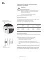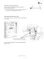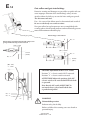
1
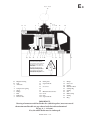
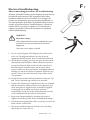
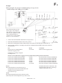
Read and understand this Operation & Maintenance Manual before operating or servicing this equipment. Operation & Maintenance SCANDO 450 & 650 Construction Hoist XXX Translation XXX Translation Original instructions This manual is only applicable if the manufacturing number indicated below corresponds to the manufacturing number stamped on the identification sign of the equipment. Where there is a conflict contact your ALIMAK representative. YOUR HOIST HAS: Manufacturing No.: Year: Part No. 9100273 - 1 10 2012 - 11 - 01 If the bottom right corner of this book is cut, the book is only valid for illustrative use! BACK FOREWORD This product is designed and manufactured to meet strict quality and safety standards. This manual is intended to provide advice and instructions to the operator and qualified service personnel so that they can safely control the situations which can occur when the product is used, and can carry out the required service and maintenance on the product. This manual shall always be available in the box on the machine intended for this purpose. Potential risk for user or equipment is indicated in the following way in this book: DANGER indicates an imminently hazardous situation which, if not avoided, will result in death or serious injury. WARNING indicates a potentially hazardous situation which, if not avoided, could result in death or serious injury. CAUTION indicates a potentially hazardous situation which, if not avoided, may result in minor or moderate injury. IMPORTANT: Information with these headings indicates the possibility of damage to the equipment. WARNING! The equipment should not be operated if Operation and Maintenance Manual is missing. Misuse of this equipment could result in personal injury or property damage. Photographs and drawings are illustrative only and do not necessarily show the design of the products on the market at any given point in time. The products must be used in conformity with applicable practice and safety regulations. Specifications of the products and equipment presented herein are subject to change without notice. CONTENTS IMPORTANT SAFETY INSTRUCTIONS OPERATING INSTRUCTIONS SERVICE AND MAINTENANCE TROUBLESHOOTING Appendix: Check LIST Tightening Torque Text and illustrations by Håkan Lindström Copyright © Alimak AB, 2004. All rights reserved. C D E F IMPORTANT SAFETY INSTRUCTIONS Safety instructions............................................... C 1 The user’s own protective measures................. C 3 ALIMAK 34595 - 1 /01 C0 C1 Important Safety Instructions Over the years serious accidents have occurred during the erection and dismantling of rack and pinion hoists. Common to these accidents has been the ”human factor”, i.e. non adherence to proper safety procedures and common sense. This document affects the personnel involved in the erection, dismantling and servicing of such equipment. Some examples: Leaning over the safety railing on the car roof while the hoist is moving upwards can cause you to be struck by a tie, counterweight or a cable guide. Incomplete installation of mast bolts can cause separation of the mast sections, leading to the fall of the car with subsequent loss of life or serious injuries. c1 Avoid the risk of accidents by carefully studying these instruc tions regularly. Think clearly! Do not rush the work and always check to make certain that the work is being done properly. SAFETY FIRST! Safety instructions Local safety regulations – All local regulations shall apply. Weather conditions – Installation outdoors – Do not erect or dismantle hoists if wind speed exceeds 12.5 m/s. (28 mph) or as governed by local regulations where more stringent. Preparation – Read and understand the Instruction Manual before the work begins. – Barricade or rope off the area before erecting or dismantling. – No admittance to the hoist car by unauthorized personnel during erection or dismantling by unauthorized personnel. Safety equipment and protective clothing – Prescribed safety equipment and clothing such as hard hat, safety shoes, safety belt, etc. shall be used. – Loose fitting clothes such as scarves must not be used as they might become entangled in moving parts. ALIMAK 34596 - 1 /01 c2 C2 General – Read all Warning and Instruction Signs. – Keep the work area clean. Any oil spillage must be removed immediately to avoid the risk of slipping. – Never climb on the mast. c3 Always lock the main ”ON/OFF” switch with a padlock to prevent unintentional operation while service/inspection work is carried out. – During erection, dismantling or hoistway inspection, the hoist must always be operated from the car roof. When working from the car roof take precautions to avoid being struck by mast ties, cable guides, landings, counterweight, structure openings, etc. while hoist is moving. – During mast erection/dismantling and when servicing a hoist with dual cars, the main switch at the ground landing, as well as the main switch in the car which is not being serviced, must be switched off and locked. This in order to ensure no accidental moving of the car. – Before carrying out any service work, the ”Normal/Inspection” switch in the control panel on hoist car must be placed in the ”Inspection” position. This is of greatest importance especially for hoists with ”Auto return” or similar remote control function. – When the control equipment on the car roof is to be left on temporarily during installation/dismantling or service, the main switch in the control panel of the hoist car must be switched off and locked in order to ensure no accidental moving of the car. – Under no circumstances the hoist, single or dual, shall be driven if there is a person within the ground enclosure, on the mast or tie. c4 The main ”ON/OFF” switch must be in the ”OFF” position before the panel door can be opened. – Complete each item of work before starting a new one or taking a break. This is especially important when bolting mast sections and installing ties. Mast and mast ties – The maximum tie distance, prescribed in the manual or on Installation drawing, must not be exceeded. Bolted joints shall always be tightened to the required torque – as prescribed by the Instruction Manual. – If any structural damage or severe corrosion is seen on such items as mast sections or mast ties, the hoist must be imme- diately taken out of service and the extent of the damage be determined and corrective action taken before the hoist is put into service again. – All mast accessories required to be installed on the mast must be secured properly during installation in order to avoid the object falling and thereby possibly causing personal injury and/or property damage. ALIMAK 34597 - 1 /01 C3 Electrical power Work performed on electrical equipment must be carried out by competent personnel, trained for such work. The power supply must be switched off and locked before work is performed. Sound level in hoist car Sound level in the hoist car during travel was measured at: ≤ 85 db(A). Spare parts Unauthorized spare parts are not to be used. Only ”Alimak Genuine Spare Parts” are to be installed. The user’s own protective measures Authorization of hoist personnel A routine that guarantees continuous product training (Authorization), that was done during the hoist installation, must be set and maintained by a responsible person. Contact Alimak or an Alimak representative, if this training is required. Protection at the landings It is recommended that overhead protection is furnished at landing entrances to protect against falling objects. Accessible areas adjacent to hoistway Scaffolding, platforms and other accessible areas located closer than 0.5 m (1 ft. 8 in.) must be provided with 2.0 m (6 ft. 7 in.) high enclosures or in accordance with applicable local regulations. With safety distance 0.5 m (1 ft. 8 in.) or more a 1.1 m (3 ft. 7 in.) high two row safety railing with toe boards is sufficient – if the hoist speed is 0.7 m/sec (135 fpm) or less. For speed more than 0.7 m/sec. (135 fpm) the safety distance must be increased to 0.85 m (2 ft. 9 in.) according to SS - EN 12159 # 7.1.2.2. Illumination of landings The adequate site lighting shall be provided to illuminate the landings over the full height of travel of the hoist. Landings erected at site Each landing shall be dimensioned for the maximum load of the hoist and fulfil the above stated criterias regarding safety distances. ALIMAK 34598 - 1 /09 C4 Inspection after major modifications or accidents Inspection and testing should be carried out after major modifications or after an accident to make certain that the hoist operates properly. Working under the hoist car When working under the hoist car, always secure the car mechanically, by safe means, i.e. the car to mast lock device. Or other suitable certified object. The hoist’s main disconnect switch must always be turned off and padlocked during the operation. Stop blocks of rubber Part. No. 9115148-000 Transportation of pallet truck or other wheeled equipment in the hoist car To prevent such equipment due to malfunction or negligence, may run out of car, stop blocks of rubber or similar mechanical stop on the car floor to be constructed to prevents this. Pallet truck/ equipment including load must not exceed max. load acc. to load sign in the car. Maximum allowable point load on the car floor from a 100 mm (4’’) wide roller of dia. 100 mm (4’’): Plywood floor = 500 kg (1100 lbs.) / roller Aluminium type sandwich floor = 1000 kg (2200 lbs.) / roller Loading/ unloading of the above mentioned equipment must be performed with lowest possible speed. Stacked goods Assemble several blocks using a rope, chain or threaded rod to suit the equipment in question to be transported Stacked goods on pallet or similar that may slide or collapse shall always be properly secured in a safe manner with respect to the risk of crushing. At the end of the shift ALWAYS drive down and park the hoist at the base landing, where the machine’s best possible location is, if extreme high wind speeds should occur. Also switch off and lock the main switch with a padlock to prevent unauthorized use. ALIMAK 35054 - 1 /09 D0 OPERATING INSTRUCTIONS Instructions for use.............................................. Operating instructions....................................... If the hoist does not start.................................... If the hoist suddenly stops.................................. If the hoist has been driven against the final limit cam..................... Securing the position of the car on the mast.......................................... Emergency access to car and enclosure........... ALIMAK 34599 - 1 /04 D1 D2 D6 D6 D8 D9 D 10 D1 Instructions for use Instructions to the user/operator on how the equipment is to be handled are presented below. These instructions will also be found on a plate in the hoist car. Illegible and missing signs must be replaced. SAFETY INSTRUCTIONS Prior to any use of this hoist perform daily safety procedures below, as well as any required maintenance and lubrication specified in the Operator’s Manual. DAILY PRE-OPERATION CHECKS 1. Check that all emergency stop switches and the final limit switch are working. Make test runs with each one of the switches in “Off”-position. 2. Check all electrical interlocks by making test runs with: a) Ground enclosure gate open. b) Car entrance gate open. c) Car exit gate open. d) With car trap door open. e) Each landing gate open. f ) Wire equalizer switch in ”Off” -position – if supplied. The hoist must not start. Be sure to check only one switch at a time. 3. Check all mechanical interlocks by making test runs and at the same time try to open the gates. Car and landing gates must remain locked until the car stops at the landing. 4. Check the condition and function of all springs on all cable guids. 5. Check function of limit switches by making test runs. Also check fastening of all limit ramps and switches. 6. Equipment and materials not associated with the hoist shall not be attached to the hoist in any manner. SPECIAL WEATHER CONDITIONS 1. In case of storms, tornados, hurricanes or earthquakes, all vital parts of the hoist must be inspected and tested by an expert or authorized local inspector prior to use of the hoist. 2. Hoist installed outdoors must not be used when wind velocities exceed 20 m/sec. (For USA and Canada 40 mph). 3. Always park the hoist at the bottom landing at the completition of work to prevent collapse of the equipment, should extreme high wind speeds occur. Where icing can take place, remove ice from mast and hoist cables before using hoist. Note that the user/operator is responsible for ensuring that the daily ”Safety Inspection” has been carried out BEFORE the hoist is put into service. ALIMAK 34600 - 1 /08 D2 Operating instructions Control equipment, relay control with joystick 1. Check that there is nothing which can constitute an obstacle in the path of the hoist. Keep this constantly under observation. 2. Switch on the main ON/OFF switch at the ground landing. d1 3. Make sure that the maximum permissible load, according to the information on the load plates in the hoist, is not exceeded. 4. Close the landing gates and the hoist car gates fully. 5. Move the joystick towards the symbol for the desired direction of travel. The hoist will now start. The joystick will automatically return to the mid position and the hoist will stop as soon as the joystick is released – if the control circuit is wired without self-holding contactors. The Stop button must be depressed if the control circuit is wired witH self-holding contactors. If the hoist mast is provided with cams for ”Stop Next Landing”; Depress the button with the symbol for this function just before you have reached the desired landing. The hoist car will then stop automatically at the level at the landing. At top and bottom landings the hoist car will stop auto- matically due to the limit cams in the mast. Control equipment, ALC with joystick 1. Check that there is nothing which can constitute an obstacle in the path of the hoist. Keep this constantly under observation. 2. Switch on the main ON/OFF switch at the ground landing. 3. Make sure that the maximum permissible load, according to the information on the load plates in the hoist, is not exceeded. 4. Close the landing gates and the hoist car gates fully. 5. Move the joystick towards the symbol for the desired direction of travel. The hoist will now start. (Control circuit wired with self-holding contactors.) 6. Depress the ”Stop Next Landing” button, just before you have reached the desired landing. The hoist car will then stop automatically at the level at the landing. At top and bottom landings the hoist car will stop auto- matically due to the limit cams in the mast. ALIMAK 34601 - 1 /01 Control equipment, ALC with keypad D3 Press the button(s) for required landing. The hoist will automatically stop at the selected landing. Example: If you want to stop at the 12th landing; Push button 1 + 2 and end finish by pushing the ENT. button a 86 When carrying out service and inspection work When it is necessary to operate the hoist from the car roof, in order to carry out service and inspection work, the switch in the electric cabinet in the hoist car shall be set in the ”Inspection” position. The switch then breaks the self-holding function of the control system and the landing control circuits. This means that the hoist will stop as soon as the push button / joystick is released and that the hoist can only be operated from the roof of the car. Additional functions ’’Run enable’’ and ’’Soft-stop’’ Frequency converter operated hoists have both feature ’’Run enable’’ and ’’Soft-stop’’ working together on the same pushbutton. The features are used according to the following but in Inspection mode, only: – First push the ’’Run enable’’ push-button marked with an opened up padlock. – Choose direction and push the ’’Up’’ or ’’Down’’ push- button. – Release the ’’Up’’/’’Down’’ push-button at the intended level – but keep the ’’Run enable’’ push-button depressed until the hoist stops. Selector switch ”Car only” The selector switch ”Car only” (marked -S 107) inside the B-panel disconnects all signals from the landings, which means that the hoist can only be operated from inside the car. Ensure that this switch is actuated when intended to run the car in operator control mode only. ALIMAK 34602 - 1 /05 Note: This switch is located outside the car roof electrical panel for hoists delivered to Australia. D4 Alimak Lift Control ALC Two different control systems In the main software there are two different control systems available: Semi-Automatic (or Stop Next Landing) and Collective. The ALC system automatically selects the control system. Semi-Automatic control system This is the most common control system available in the ALC controller and operates without any landing cams. The position of the hoist is determined by counting impulses generated by the pulse encoder attached to the car. The hoist can be operated from inside the car and if chosen, also from the landings by using Up, Down and Stop Next Landing push-buttons. By pressing a button for Up or Down, the hoist starts travelling in the chosen direction. When the hoist approaches the desired landing, the button Stop Next Landing is pressed. The car will then stop automatically at the landing. Calls/destinations from the landing box unit with Up, Down and Stop Next Landing push-buttons operate on 230 VAC control wires between the car and the landings via the base-panel. A destination order from the car has three seconds priority over landing calls. Collective control system This is the most advanced control system available in the ALC controller. The hoist can be operated from inside the car by destination push-buttons and if chosen, also from the landings. Each landing is provided with two call buttons, one for each direction of travel. This system receives all destination orders from inside the car, as well as calls from the landings. The information is memorized and processed within the system. During the travel the hoist will automatically stop at all floors which have been addressed. ALIMAK 34603 - 1 /01 If operation from inside the car is done by means of the keypad, access to the Stop Next Landing control system is automatic. The keypad is consisting of 15 push-buttons. 12 of them are for the collective system: 0 – 9, ENT and CLR. The other three push-buttons are for the Stop Next Landing system: Up, Down and Stop Next Landing, which operate in parallel with the collective system. On every landing there is one I/O-card with two external illuminated call buttons; one for each direction of travel. The I/O-cards are connected to a six wire communication circuit that terminates in a base CPU (Central Processor Unit) inside the base panel. The information is transmitted from the base CPU to the hoist CPU (main unit) on a two wire communication circuit in the trailing cable. D5 a 86 Information and fault indications on displays A hoist equipped with the Alimak ALC control system and landing level display on the hoist electrical panel has access to a fault indication system. Faults indicated at the display are the following: Safety circuit broken Door circuit open with hoist between landings Fault in door closing sequence Overload Hoist in Inspection or in Programming mode Hoist does not start within start time/ fault on pulse encoder Pushed in emergency stop button at base landing Speed fault / Config. fault / Calib. fault / Over heat Fault in control circuit Information Door(s) open Calibration drive Inside car; Closed landing At the base landing; connection to the car CPU broken Landing circuits disconnected at the base level (Operation from car only ) See separate manual P/N 9081 541- sub. for detailed ALC programming instructions. ALIMAK 34604 - 1 /05 D6 If the hoist does not start – check: – that the main ON/OFF switch at the ground landing is in the ”ON” position and that the hoist is supplied with electric power. – that no ”Emergency Stop Button” is in its depressed position. d7 – that the final limit switch is not activated. If the final limit switch is activated – see heading ”Manual cranking”. – that the roof trapdoor and car gates are fully closed. – that all the landing bars or gates are fully closed. – that the ”Normal/Inspection” switch in the electric cabinet in the car is in the ”Normal” position. – that no circuit breaker for control power has tripped out. If the hoist still does not start, see the instructions in the section ”Electric troubleshooting”. If the hoist suddenly stops If the hoist stops between landings due to a power failure or any other electric failure, such as blown fuses, tripped motor, overload protector, etc., it can be manually lowered to the next lower landing for unloading. Only slide the hoist short distances at very low speed in order not to exceed the normal operating speed of the hoist. If excess speed occurs, the hoist’s safety device will automatically trip and stop the hoist. If the safety device trips during sliding There is NO power to the drive motor 1. Crank the hoist approximately 20 cm (8 in.) upwards according to the instructions ”Cranking” to release the mechanism of the safety device. 2. Try to slide the hoist again. The safety device can be allowed to trip 2 to 3 times – before it must be reset to neutral position The reason why the safety device must be reset is that the brake cone after each tripping will be forced harder against the brake lining, stopping distance will be decreased and braking more abrupt. Note that the safety device must be reset as soon as the hoist reaches the ground! ALIMAK 34605 - 1 /01 D7 Sliding 1. First check applicable items on previous page. 2. Switch off the main ON/OFF switch on the electrical cabinet. Manual sliding with the motor brake lever – Open the trap door and climb to the car roof. – Lift the brake lifter/-s on the motor to allow the car to slide down to the next lower landing. IMPORTANT: Only slide short distances with maximum 1/3 of normal operating speed. Stop at least 5 (five) minutes every 20 meters (65 ft.) so that the brakes have time to cool off. Overheating can cause the brake function to deteriorate. Sliding by means of optional centrifugal brake – Pull the brake release handle downwards and keep it down to allow the car to slide down to the next lower landing. The 3rd el motor brake can be disengaged with an ratcheted tie down, where applicable. Brake release handle inside the car IMPORTANT: Always lower handle to its most bottom position to prevent overheating of motor brake. Release the handle immidiately if power suddenly comes back and the lift starts. If sliding of the car is not possible – stay in the car and call for assistance. Construction hoist with electrohydraulic load ramp Construction hoists with foldable electrohydraulic load ramp must be lowered gradually, in steps to the bottom landing to offer passengers to leave the car in a safe manner – via the entrance door. Reason for this is that the electrohydraulic load ramp cannot be operated without electrical power. It is possible to manually slide the machinery with the lever on the centrifugal brake too DANGER! Falling hazard. Take no risks exiting the car – wait for assistance. Will cause severe personal injury or death. ALIMAK 34606 - 1/10 d 34 D8 If the hoist has been driven against the lower final limit cam If, due to heavy load and poor brake function, the hoist has been driven against the final limit cam at the bottom landing so that the power to the drive unit has been cut off, the hoist can be cranked back manually to the normal landing level. The motor brake should be checked by trained/authorized personnel, before the hoist is put back into service. OFF WARNING! Crushing hazard. ON Always disconnect the power by means of the main switch on the electrical panel before working on the machinery. d1 Can cause severe personal injury. Cranking 1. Release the lower brake (or both lower brakes on 3 motor machinery) with one / two ratcheted tie down. 2. Apply a ratchet spanner with socket dia. 19 mm on the hexagon shaft end of the brake motor. 3. Pull the ratchet spanner on the applied motor brake in clockwise direction. WARNING! Violent stroke of the ratchet spanner. Do not release ALL brakes at the same time when the ratchet spanner is applied on the shaft end of the brake motor. Can cause severe personal injury. Note. The hoist can be driven off the final limit cam by using the equipment intended for drop test. See headline ”Drop test” in chapter Service and Maintenance for instructions. ALIMAK 34607 - 1 /02 D9 Securing the hoist car on the mast A car locking device is located behind a cover panel in the car wall – intended to be used during transport of the hoist base unit, or when service work is to be carried out on the mast under the car. The car locking device can be applied anywhere on the mast’s rack. Function Remove the cover panel. Push the cog segment in proper location and tighten it fully against the mast’s rack with the M-16 bolt provided. AFTER use – reset the cog segment to its outermost position. The locking device is mechanically interlocked and electrically supervised in such way that the covering panel cannot be reinstalled if the cog segment is not fully reset. A cam, rear on the cover panel closes an electrical contact in the hoist’s safety circuit when properly reinstalled. The hoist cannot be started if the cover panel is missing. IMPORTANT In conjunction with disassembling the drive unit from car ... ... the motor brakes must be lifted and the drive unit lowered by gravity so that the car’s own weight and possible load are transferred from the drive unit’s pull rods – to the car locking device cog segment and the mast’s rack. Before resetting the cog lock segment ... 30° ... in conjunction with assembling the drive unit, the electric motors must be cranked in upwards direction with a ratchet spanner (approx. 30°) one by one in sequence 1st, 2nd and 3rd, as noted below. Repeating the procedure – until the car’s own weight is placed on the machinery’s pull rods. During the operation described above the car must be located at the base landing and the main power switch turned and locked with a padlock in Off-position to prevent accidental starting in downwards direction. The ratchet spanner must NOT be replaced with a fixed wrench due to the ratchet spanner’s free rotating in opposite direction. 3 2 1 ALIMAK 34608 - 1 /08 D 10 Emergency access to car and enclosure Door in ground enclosure – Use the triangular key from the hoist tool kit to release the ground enclosure interlock and enable the door to be opened from the outside. Door lock of mechanical type with integrated electric switch or with separate electric switch – From the inside of the ground enclosure the door interlock is released by pushing the actuator on the door interlock. ALIMAK 34609 - 1 /02 D 11 Doors on car Door lock of solenoid type with integrated electric switch – From the inside of the car the door interlock is released by turning the solenoid’s lock shaft to unlocked position. – Use the key to manually push the lock solenoid in unlocked position to enable the door to be opened from the outside. Door lock of mechanical type with separate electric switch – Use the triangular key to open the trap door and climb up on the roof. – From the outside of the car the interlock of the door is released by pushing the interlock hook to released position. ALIMAK 34610 - 1 /01 E0 SERVICE AND MAINTENANCE Service and maintenance.................................... Adjustment and wear limits............................... Optional centrifugal brake................................. Drop test................................................................ Resetting the safety device................................. Lubrication diagram........................................... Optional load ramp............................................. Preservation for long time storage................... ALIMAK 34611 - 1 /06 E1 E6 E 16 E 18 E 20 E 22 E 24 E 27 E1 Service and maintenance In order to avoid unnecessary breakdowns, those responsible for the service and maintenance of this equipment must regularly ensure that all scheduled maintenance work is carried out at the recommended intervals according to the maintenance program below. Adjustments and replacement as a result of inspection, must be carried out by trained/authorized service personnel. Only ALIMAK Genuine Spare Parts must be used. WARNING! Unintended operation. Always put the hoist’s ”Normal/Inspection” switch in Inspection position before carrying out any service work. When leaving the car without having completed the service work or to carry out service, the main switch must be switched off, locked and tagged. Failure to follow this warning can cause death or personal injury. Service intervals Intervals based on operating time shall be followed in the first instance. If the hoist is used only periodically, the first applicable interval to be reached shall be followed. e1 Frequent starts and stops! Service interval 60 hours is based on operation on low rise buildings, with 4 storeys (approx. 12 m) or less, common in Sweden and northern Europe. For 6 storeys (approx. 18 m) or more, corresponding service intervals can be increased to 120 hours but never exceeding once a month. Checklist (log book) Checklist, with room for notes on maintenance executed, will be found at the end of this manual. Use it! Service and maintenance schedule See the appendix at the end of this manual for bolt tightening torques. IntervalPart Instructions 60 operating 2. Sign plates/ hours or at least instruction once every month manuals Check that all signs are in position according to the spare parts manual, and that they are legible. Check also that the documentation according to the documentation box is available. 3. Safety device Check with the user/users if the safety device has been tripping without cause or if noise can be heard from the device during operation. For further details, see the instructions for checking wear on the safety device under the heading ”Adjustment and wear limits” ALIMAK 34612 - 1 /02 E2 IntervalPart Instructions Check the oil level and refill, if necessary. Leaking seals shall be replaced by trained/authorized personnel. 4. Gear box 5. Counter roller(s) Check that all bolt joints are properly tightened. at the rear of the machinery plate and safety hooks, guide rollers on the hoist car frame. 6. Attachment of Check that all screw joints are properly tightened. machinery and safety device 7. Electric motor brakes Check that the car stops within acceptable limits, specified later in this chapter. See the special instruction for checking the brake torque with a spring balance – if car stopping positions exceeds stated values. Check the play between the electromagnet armature and the rotating brake disc according to instructions later in this chapter. 8. Hoist cable(s) Check the cable for wear and to ensure that no kinks occur. Check also the attachment of the cable in the cable support arm on the hoist car and the fixture in the hoist mast – where a cable guiding device and trolley are furnished. 9. Cable basket, Clean the cable basket. If the cable guiding device is of a type for power and where applicable control cables, which has been taped together, check the tape and, if neces- sary, reinforce it along the entire length of the cable. 10. Interlocks Check the function of all mechanical and electrical interlocks on all landings and on the hoist car. See the instructions under ”Safety Instructions”. 11. Car floor and roof Clean the car floor and roof. 12. Scaffolding adjacent to hoist Check that the distance from the hoist car to landings, scaffolding, balconies windows or any other location where persons may find themselves, are not less than regulations dictate. Point out any infringements and risks of injuries to the site manager. 13. Lubricating See the instructions in the ”Lubrication diagram”. Also check the rack and counterweight guide rail for possible damages, misalignment and attachment, when lubricating. 14. Optional hydr. load ramp See the instructions ”Maintenance instructions for optional el./hydraulic load ramp” later in this chapter. 120 operating 20. hours or at least 6 times a year 21. Hoist mast 22. Mast ties Check visually that all screw joints of all racks and mast joints are properly tightened. Also check the screw joints for attaching the mast to the base frame. Check that all screw joints in all mast ties are properly tightened. Also check attachment to structure. 23. Final- and normal Check attachment and function. limit switches with associated cams 24. Cable guides Check the cable guides with regard to attachment, function and installation in the mast in relation to the cable support arm on the hoist car. 25. Cable trolley, where applicable Check that the cable trolley does not come in contact with the buffer frame at the ground landing and that the trolley is parallel to the mast tubes. Check also the function, attachment and wear on the guide and cable rollers and that the cable wheel on the trolley runs smoothly. ALIMAK 34613 - 1 /10 Interval Part 26. Base slab/pit 27. Gates on hoist car and enclosures Instructions E3 Remove all debris (or trash), which may have fallen on/into the base (or pit). Check the function, attachment and wear on rollers and wire ropes. Check to ensure that rubber absorbers are in place. Also check that the rubber cover for the biparting gate is in place. Contact Alimak or representative if an oil leakage occurs on el./hydraulic load ramp – where applicable. 28. Buffers for hoist Check that the buffers are in position and in a proper condition. car 29. Signal equipment Check the function of the control device, alarm signal, lighting, automatic and lighting stop at landings and, where applicable, voice communication system. 30. Emergency lighting Switch off the main ON/OFF switch in the hoist car and check to ensure that the emergency light functions. Switch on the main ON/OFF switch and check that the LED on the battery charger is illuminated. Applicable for battery charger to DOL driven hoists without floor call selecting system, type ALC – only. 31. Rack and pinion Check the wear on the rack and pinion according to the instructions under the heading ”Adjustment and wear limits”. 32. Enclosures Check that there is nothing in the vicinity of the landings, which can be used as a ladder, or can reduce the correct height of the enclosure in any way. Point out any infringements and risks of injuries to the site manager. See the instructions in the ”Lubrication diagram”. 33. Lubricating 34. Emergency Check by test that the emergency lowering device works properly and that lowering device the handle is fully reset after operation. See the instructions in the under – where appl. heading ”Optional centrifugal brake”. 400 operating 40. Guide rollers Check wear and bearing play of the hoist car rollers. Also check that the rollers can move axially. Adjustment and replacement, when required shall hours or at least be carried out by trained/authorized service personnel. 4 times a year 41. Electric motor If necessary, clean the cooling flanges of the electric motor. Have the electric motor’s permanently greased ball bearings replaced after 20.000 hours of operation by appropriately qualified personnel. Please contact Alimak Service department to schedule replacement. See the instructions in the ”Lubrication diagram”. 42. Lubricating 43. Overload sensing Overload test to probe overload sensing system. system – where applicable 44. Optional erection See separate documentation regarding maintenance of optional erection crane hoists crane hoists. – where appl. 600 operating 48. Safety device hours or at least 2 times a year 49. Motor brakes Test the safety device according to the instructions under the heading ”Drop test”. Test motor brakes according to the instructions under the heading ”Static test of motor brakes”. 1000 operating 50. Shaft coupling hours or at least once a year Check vibrations and listen for noise from shaft couplings between motors and gear boxes. If play occurs, service must be carried out by trained authorized personnel. 51. Electric wiring Check all wires, sealing glands and connections. 52. Motor overload Check that the motor overload protector is set to the rated current on the protector data plate for the electric motor. ALIMAK 34614 - 1/09 E4 Interval Part Instructions E5 53. Deformations/ mechanical damage Inspect the equipment visually in its entirety for deformation/mechanical damage to mast tubes, diagonal members of the mast sections, mast ties, gates, protective rails, floors, etc. This inspection and any actions, which may be necessary after the inspection must be performed by trained/authorized service personnel. 54. Corrosion, damage and wear Inspect the equipment in its entirety for corrosion and wear on loadbearing and force-absorbing components by the aid of an ultrasonic thickness mea- -suring instrument. This inspection and any actions which may need to be taken after the inspection must be performed by trained/authorized service personnel. A method for internal corrosion protection of the mast tubes is available, please contact your ALIMAK representative. 55. Hoist mast Check that all screw joints of all racks and mast joints are properly tightened. Also check the screw joints for attaching the mast in the base. See the instructions in the ”Lubrication diagram”. 56. Lubricating 57. Centrifugal brake – where applicable Dismantle the brake motor from the centrifugal brake and inspect the brake hub with linings. See the instructions in the under heading ”Optional centrifugal brake”. 58. Check the hydraulic system’s chock load valve. The load ramp must be able to close with a 20 kg weight placed farthest out on ramp. But NOT be able to closed if the weight exceeds 25 kg or more. For further details, see end of this chapter. El./hydraulic operated load ramp – where applicable 59. Hydraulic oil buffers – where applicable Check the hydraulic oil level on the buffer’s dip stick and refill, if necessary. Make a test run with the hydraulic buffer’s limit switch in ’’Off ’’-position The hoist must NOT start. Put suitable object between the hydraulic buffer’s push rod and the limit switch’s actuator during the test. Annually 60. Complete hoist 61. Corrosion protection devices Have the complete hoist checked by a qualified technician. Replace the corrosion protection devices which are located inside the elec- trical panels according to the following: Main panel (M-panel) 2 pcs. P/N 3002 301-105 Car top control panel (VFC) 2 pcs. P/N 3002 301-105 Car top control panel (DOL) 1 pcs. P/N 3002 301-101 Base panel (B-panel) 1 pcs. P/N 3002 301-105 Landing control stations 1 pcs. P/N 3002 301-101 Every 4th year 62. Safety device or latest according to sign on the safety device Replace the complete safety device by returning the device to the Alimak Factory. Only Alimak factory tested devices are to be used. The safety device is sealed and unsealing the device is prohibited. ALIMAK 34615 - 1/09 E6 Adjustment and wear limits Car stopping positions Normally B – empty car Sill e2 B C Maximum C – with pay-load If the distance between actual stopping positions empty/ fully loaded car exceeds value A stated below, the brakes must be checked by trained/authorized service personnel. Note: Parking brakes for VFC operated hoists must ALSO be checked for proper function by testing with rated load or by torque wrench. Hoist type A B C with direct started el. motors 110 mm (4.3 in.) 40 mm (1.6 in.) 70 mm (2.7 in.) ALC II controlled direct on line 60 mm started electric motors (2.4 in.) 30 mm (1.2 in.) 30 mm (1.2 in.) with VFC operated el. motors 5 mm (.2 in.) 5 mm (.2 in.) 10 mm (.4 in.) Static test of brake torque A static motor brake test shall be carried out at least 2 times a year – preferable in conjunction with the safety device drop test. Single motor machineries Single motor machineries are tested statically with rated load and additionally 25% overload loaded in the car. Dual or triple motor machineries Dual or triple motor machineries are tested statically with rated load and one motor brake disengaged, ascertaining that the car does not start to move during the test. ALIMAK 00000 ALIMAK 34616A - 1 /09 E7 Checking brake torque with torque wrench To be carried out periodically by trained service personnel ONLY! If the machinery is of single motor design the hoist car must be lowered and resting on the buffer springs before checking is allowed to take place. WARNING! Violent stroke by the wrench Switch off and lock out power supply before checking brake torque. Can cause severe personal injury. This test is carried out by means of a 19 mm socket and a torque wrench applied on the motor shaft according to the following: – Release the brake and turn the lever up and down to determine the total cog play. – Then turn the wrench upwards, within the determined cog play. Alternative: The car to mast lock device can be used to ease this procedure. – Reapply the brake and pull the torque wrench downwards until the brake starts to slide. If the brake starts to slide before the torque wrench does – adjust the torque wrench to a lower torque and repeat the procedure until the actual brake torque is determined. The electromagnetic disc brake shall have indicated torque ±15%. If indicated brake torques are not achieved, call for trained authorized personnel. ALIMAK 34616B - 1 /09 ALIMAK 00000 Motor power Brake torque 7,5 / 8,8 kW 170 Nm 11 / 13 kW 170 Nm 22 / 27,6 kW 170 Nm (125 lbf. x ft) E8 Inspection of friction disc and electromagnet Motor brake type Binder WARNING! Unintended operation Bring the car down to rest on the buffer springs. Switch off, lock and tag the main switch before inspection can take place. Can cause severe bodily injury or death. Check air gap by means of a feeler gauge. Replace the friction disc Air gap A / B between magnet housing and armature The friction disc must be replaced before the air-gap exceeds maximum (B) mm. Nominal value (A) mm. Fixing bolts (6 pcs) tightening torque: 25 Nm Motor Nominal Maximum Air Nominal size air gap air gap gap coil resistance A B CD 0.35 mm 1.5 mm 1.7 mm≈ 130 Ohm 8.8 kW 13 kW 0.35 mm 1.5 mm 1.7 mm ≈ 130 Ohm Hand release mechanism Check air gap (C) for manual release device according to sketch. If the brake cannot be electrically released, check: – that the rectifier is in order and energized. – that the brake contactor is in order. – the voltage to the magnet coil (nominal 102V DC). – the resistance of the coil (nom. approximately D Ohm, see table). Air gap C Manual release device Replace electromagnet housing with coil if the coil is defective. IMPORTANT: Do NOT replace the brake’s rectifier of the type with booster function with a common rectifier type. ALIMAK 34617 - 1 /06 E9 16:1 – 16:3 16 20 5 8 17 11 25 24 21 9 2 7 22 1:2 1:1 10 18 4 19 13 23 26 IMPORTANT INFORMATION RE BRAKES FOR ALIMAK ELECTRIC MOTORS The manual brake release mechanism’s axial play must never be allowed to become ZERO due to its affect on the brake torque. Non existing axial play will cause overheating and damaged leading to a deterioration of the brake function. It is recommended to change brake disc(s) after 800 – 1000 operation hours, individually, depending on load. 1:1 Magnet housing 1:2 Coil 12 Armature 13 14 Compression spring 15Sleeve 6 Flange 7 Hub 8 Brake disc 9 Friction disc 10 Fixing bolt 11 Cap head bolt 12 13 Set screw 14 15 16 Manual release device 16:1Lever 16:2Disc 16:3 Cap head bolt 17Flange 18 Fan cover 19Circlip 20 Rubber bellows 21 Sealing ring 22Circlip 23 Fan 24 Ball bearing 25Circlip 26Plug IMPORTANT: Wearing of armature and fixed brake disc (added together) must not exceed the maximum allowable air gap reduced with the indicated nominal air gap, A (= 1.15 mm). If so, the whole brake must be exchanged. ALIMAK 34618 - 1 /07 E 10 Pinion Max. worn gear Check the wear with the aid of sliding caliper. New gear New gear = 38.5 mm (1.51 in.) Max worn gear = 37.1 mm (1.46 in.) e 53 The counter roller for the pinion must be changed when the pinion is replaced. Gauge Part No. 9098411-000 It is recommended to use Gadus S3 A1300C 2 to prevent crevice corrosion between shaft and pinion. (.31”) ø 8 mm e9 Max. worn rack New rack Rack Measure with a dia. 8 mm (.31 in.) gauge rod and sliding caliper. New rack = 39.9 mm (1.57 in.) Max worn rack = 38.2 mm (1.50 in.) Gauge Part No. 9103819-000 Check the wear of the rack and adjust the drive unit guide rollers according to the following: Mast side Wearing on the rack Drive unit inclined away from the mast. (Bad) Drive unit running correct on the mast. (Good) Drive unit inclined towards the mast. (Acceptable – but higher noise level.) e 82 ALIMAK 34619 - 1 /05 E 11 B Guide roller Measure with sliding caliper. Dimensions New roller (mm) Worn-out roller (mm) A Ø 74 (Ø 2.91 in.) minimum Ø 68 (min. Ø 2.68 in.) A minimum 2 (min. .08 in.) B Guide rollers for mast tube dia. 76 mm are zinc plated (yellow roller face). Guide rollers for mast tube dia. 60 mm are iron-zinc plated (black roller face). Note that the ”wear” on the roller face must be equal – all around. e 52 Mast tubes Checking of wear and corrosion on mast sections is carried out by means of an Alimak ultrasonic tester Part No. 3002546-000. The bottom mast section must be thoroughly checked. 650 x 650 square mast section with tube dia. 76 mm (3 in.) New mast tubes t mm (inches) 4.2 (.165 in.) 6.3 (.248 in.) 8.0 (.315 in.) Max. worn out mast tubes t mm (inches) 3.1 (.122 in.) 4.7 (.185 in.) 6.0 (.236 in.) approx. 25% reduction of wall thickness 450 x 450 square mast section with tube dia. 60 mm (2 3/4 in.) New mast tubes t mm (inches) 3.6 (.141 in.) 3.2 (.126 in.) Max. worn-out mast tubes t mm (inches) 2.7 (.106 in.) 2.4 (.095 in.) approx. 25% reduction of wall thickness Note that wear/corrosion on the mast sections have an effect on maximum overhang (free top) and maximum allowed mast height as follows: Reduction of original Reduction of overhang wall thickness in % of the hoist mast in % 10% 15% 20% 25% more than 25% Reduction of mast height in % 15% 20% 20% 30% 20% 40% 25% 50% Mast section should be scrapped ALIMAK 34620 - 1 /08 e 11 E 12 Adjustment of guide rollers NOTE: Guide rollers must only be adjusted when there is NO load in the car. The following adjustments are carried out by freeing the attaching bolt/nut of the roller and rotating the eccentric shaft with the tool provided until the correct setting is attained. Then retighten the bolt. Car support rollers 1. Adjust the upper support rollers so that the car structure is parallel to the front edge of the mast frame. 2. Continue adjust the lower support rollers so that the car structure is parallel to the mast tubes in the vertical plane. Wedge Side roller Support rollers Car side rollers The side rollers must be adjusted when they are level with a horizontal frame of the mast and always adjusted in pairs. 3. Loosen the side rollers and center the car structre on the mast tubes using wedges or similar as shown. 4. Single roller: – Adjust both side rollers with air gap 0.7 mm (.027”) and lock them in this position. e 100 Car structure Air gap 0.7 mm (.027”) must be done on both side rollers AT THE SAME TIME and be adjusted with the side rollers in level with one horizontal mast frame. With a roller assembly: – Push bottom roller of the assembly against the mast tubes and adjust the air gap between the top roller and mast tube to 1.4 mm (.055”) or 0.7 + 0.7 mm and lock the assembly in this position. Drive unit support rollers 1. Adjust the upper support rollers so that the drive unit is parallel to the front edge of the mast frame. 2. Continue adjust the lower support rollers so that the drive unit is parallel to the mast tubes in the vertical plane. Guide roller nominal setting: Refer to drwg. at the end of this manual. IMPORTANT: The side rollers must NOT be adjusted closer than 0.7 mm (.027”). Only occasional contact between roller and mast tube is allowed during operation. Do not forget to retighten to correct torque after adjustment. ALIMAK 34621 - 1 /08 E 13 Side roller for single motor drive unit The side roller must be adjusted when it is level with a horizontal frame of the mast. 3. Loosen the side roller and center the drive unit parallel on the mast tubes with the upper left side roller. Setting of overload sensing system Set the overload sensing system to trip at full load and additional 10% overload. Signals from the load cells are transferred to the OSD 4 amplifier located in M-panel For more detailed information refer to separate manual P/N 9081 539 - sub. ALIMAK 34622A - 1 /09 E 14 Gate rollers and gate interlockings Extensive wearing and damages on gate rollers or guide rails can cause improper function of the interlocking’s safety circuits. Avoid accidents by daily try to start the hoist with gate opened. The hoist must not start. If so – the cause of the failure must be determined and rectified. Be sure to check only one switch at a time. New gate rollers for replacement are now accomplished with securing plates which visually indicate and mechanically prevent more than maximum allowable play. Vertical gate profile Interlock type solenoid lock Pos. ”2” Interlock type mechanical hook with compression spring and monitoring electrical switch (.31’’) 8 mm k 222 (.39’’) 10 mm 35 mm (1.38’’) Pos. ”1” Pos. ”1” 20 mm (.78’’) (.08 – .12’’) 2 – 3 mm Check the adjustment of the N C el. switch: Position ”1” = electric switch NOT activated. Position ”2” = electric switch activated. ATTENTION! Adjust the position of the NC electric switch to be activated AFTER the hook is operated. Note that the NC switch must NOT be activated when a closed and locked door is pushed and pulled. Pos. ”1” Pos. ”2” k 145 WARNING! Unintended operation Perform safety check daily. Failure to follow this warning can cause death or personal injury. ALIMAK 00000 ALIMAK 35340 - 1 /09 E 15 Measuring the radial play of the rotating shaft on the safety device 1. Clamp a support (A) on the rack with the aid of a C-clamp – approximately 1 mm (.039”) above the safety device pinion. 2. Measure the play with a feeler gauge. 3. Lift the pinion with the aid of the cranking lever from the hoist tool kit or some other suitable tool and measure the play again. A Note that the pinion may not be turned, but must remain in precisely the same position during both measurements. 4. The difference between the two measured values is the radial play in the safety device shaft. 5. If the radial play is greater than 0.6 mm (.024”), the safety device must be replaced. IMPORTANT! Test has to be done before lubrication. e 15 The rectangular holes in the car roof profile are intended to ease the replace- ment of the safety device with a common ratcheted tie down for instance. ALIMAK 34622B - 1 /08 ALIMAK 00000 E 16 Optional centrifugal brake1. WARNING! Unintended operation Bring the car down to rest on the buffer springs. Switch off, lock and tag the main switch before inspection can take place. Can cause severe bodily injury or death. Inspection of brake and brake lining 1. Disconnect the flexible ball joint (A) from the control device on the side where the Teleflex wire from the car release lever is located. 2. Loosen the vertical bolt (B) on the brake housing, which locks the control device axially. 3. Remove (pull out) the whole control device (C). 4. Inspect the brake lining through the seat (hole) for the con- trol device. Replace the brake linings when they are worn down to 3 mm (.12”) thickness. 5. Turn the control device on the opposite (right) side to check that the lock ring disengages from the brake hub. 6. Lubricate the control device with Aeroshell Grease 6 when reassembling. Every 2nd month A 1. Lubricate linkage and control cable with multipurpose oil in a spray can, type WD-40 or equivalent. Use the spray can’s additional extension tube to apply the oil inside the control cable’s external hose. C B D e 111 ALIMAK 35039 - 1 /06 E 17 Every 2nd year 1. Dismantle the brake motor from the centrifugal brake on the gearbox. 2. Clean and grease the brake hub with Aeroshell Grease 6, avoiding any contamination of the brake lining. Also check and replace the brake shoes when the brake linings are worn down to 3 mm (.12”). Reinstall and check that the brake hub is free to move. 3. Replace the control devices’ ball bearings (D) after 800 operating hours, or every 2nd year. Synchronizing of centrifugal brake and motor brake 1. Disassemble the Teleflex wire from the control device on the centrifugal brake. 2. Turn the control device into position ”3” in clockwise direction and leave it in this position. 3. Push the motor brake release lever into ”fully released position” and tighten the motor brake release wire. 4. Reset the control device to position ”1” and reassemble the Teleflex wire. Marks on control disc and the corresponding pin on brake housing The pull wire is now slack between the centrifugal- and motor brake. Position ”1” Locked centrifugal brake Position ”2” Engaged centrifugal brake. ALIMAK 35040 - 1 /06 Position ”3” Engaged centrifugal brake and motor brake released. E 18 Drop test To be carried out by trained service personnel. A drop test with full load shall be carried out for each new installation and then at least twice a year – or in accordance with local safety regulations. DANGER! Brake malfunction hazard No one is allowed in the hoist during a drop test. Will cause severe bodily injury or death. e 55 If the safety device begins to trip, or if noise occurs in the safety device during operation, the hoist must be taken out of service immediately and the local ALIMAK representative be notified for action. e 16 Drop test instruction 1. Test run the hoist in upward and downward direction to ensure that the brakes have sufficient brake torque. 2. Set the ”Normal/Inspection” switch in the electric cabinet in the hoist car into the ”Inspection” position. 3. Connect the ALIMAK drop test cable to the terminal block marked ”Drop test” in the electric cabinet in the car. Remote drop test equipment at ground landing connected on terminal inside the car electrical panel e 17 4. Attach the cable to the car adjacent to the electric cabinet and lower the push-button box to the bottom landing via the roof trap door. At the same time, check that the cable is suspended in such a way that it cannot be crushed or be obstructed when the drop test is carried out. 5. Load the car with prescribed load. Switch on the main ON/OFF switch and run the car from the ground level up minimum 6 meters (20 ft.) or 4 pcs. mast sections, by means of the ”Up” button on the push-button box on the testing cable. 6. Press the button on the drop test push-button box marked with an arrow symbol and maintain it in the depressed position. This releases the motor brake(s) and the hoist car will drop until it reaches the tripping speed and the safety device is actuated. ALIMAK 34623 - 1 /07 E 19 Release the push-button immediately if the safety device does not function and stop the hoist – at least 3 meters (10 feet) above the ground level. The brake(s) are applied when the push-button is released. If so, start the test from item 4 again. 7. Run the car upwards minimum 0.2 m (8 in.) with the drop test push-button box to release the mechanism of the safety device. Then take the car down to the normal lower landing by inching little by little with the drop test device. Be careful so that the safety device is not activated again. 8. Remove the test cable and then try to start the car in the upward direction. The microswitch in the safety device shall, when the safety device has been actuated, prevent the hoist from starting when the test cable has been removed. In other words, it must not be possible to start the hoist. 9. Reset the safety device according to instructions later in this chapter. 10.Reset the ”Normal/Inspection” switch in the electric cabinet to the ”Normal” position. If you don’t succeed with the drop test, contact nearest ALIMAK representative. Calculating the safety device stopping distance The safety device stopping distance can be measured between the end face of the safety device and the end of the indicating pin – measure ”L”, see figure. Note: the indicating pin (6) is made of a stop screw with internal hexagon grip. Pay attention to this when using a sliding caliper for measuring. Multiply measure ”L” with factor acc. to the table for the safety device in question. Safety device P/N type GF factor (xL) 9067360-sub.188.5 9095340-sub. – ” – 0183144-sub.– ” – GFD 9094320-sub.314.2 0196784-sub.301.6 Safety device P/N type factor (xL) GFD mk II 9101991-sub. 267.0 9099255-sub. –”– L GFD mk III 9107880-sub. 333,8 e 19 IMPORTANT! The safety device must be exchanged if measure ”L” exceeds the value stated on the safety’s sign. ALIMAK 34624 - 1 /08 E 20 Resetting the safety device If the safety device trips during normal operation, a careful check must be made of the motor brake(s), transmissions, pinion, rack and all guide and counter rollers by trained/ authorized service personnel, before the safety device can be reset. The cause of the tripping must be determined and rectified. e 20 The safety device may be reset after a drop test, without having to carry out the checks listed above. WARNING! Falling hazard Never reset the safety device above ground landing. Can cause severe injury or death. Exchange intervals, see sign on safety device! Rating plate on the safety device A socket intended for a 3/4’’ drive ratchet comes with the Scando 650 hoist delivery to simplefy the safety device’s resetting procedure. An drive extension tube further simplify the procedure. (The 3/4’’ drive ratchet is NOT a part of the hoist delivery). ALIMAK 34625_A - 1 /08 E 21 Resetting Tightening torque 20 Nm 1. Switch off the car main switch. 2. Unscrew the screws (1) and remove the cover (2). 3. Unscrew the screws (3). 4. Use the sleeve (5) and the cranking lever (4) to back off the nut (7) until the end of the pin (6) is on a level with the end surface of the safety device. 5. Install the screws (3) and the cover (2) with the screws (1). 6. Remove the protective cover (9). 7 Tighten the screw (8) by hand as far as possible and then a further 30° by means of the sleeve and the cranking lever (4) – in the direction indicated by the arrow on the cover. 8. Reinstall the protective cover (9). 9. Switch on the main switch and run the car up minimum 20 cm (8 in.) upward to reset the centrifugal weight of the safety device in its neutral position. 10. Make a test run. e 21 From a safety point of view the safety device must never be dismantled more than is necessary to reset it as described above. For this reason the safety device is sealed. ALIMAK 34625_B - 1 /08 E 22 Lubrication diagramxxxxxx INTERVALITEM LUBRICATING POINT 60 operating hours 1 or at least once a 2 month LUBRICANT VOLUMEINSTRUCTIONS Gear box/-es Check the oil level. Shell Gadus S3 V100 C Grease nipple. or equivalent Part No. 3001 396-250 Safety device, and idle gear on the rear of the plate where applicable 3 Rack Alimak spec. grease We recommend use of a Also use spray to Part No. 3001396-108 hand held battery operated corrosion on thegrease pump. Refer to machinery pull rod´s cup product sheet No. 1291. springs where applicable Alternative: Lubricate during lowering. Cog spray for open gear Take lift out of operation for 2 – 3 hours to permit the spray to congeal. 4 Cable support arm, guides Ali-low-fric compound Grease slide surfaces. Do and trolley, where applicable. Part No. 9052 045-000 not grease mast tubes – the cable trolley may get stuck 120 operating 9 Door interlocks and ramps hours or at least 6 times a year11 Landing doors – Roof trapdoor and electric cabinet hinges – Electric / hydraulical load ramp – where applicable Shell Gadus S3 V220 C Grease bearings and slide Part. No. 3001 369-107surfaces. Shell Gadus S3 V220 C Grease bearings and slide or equivalent surfaces. Spray can with multipurpose oil type WD 40 or equivalent Hydraulic oil according to Check oil level. ISO VG32 or Also see page E23. Q8 Hindemith LT P/N. 3001 225-020 1000 operating – Hydraulic oil buffers – where Hydraulic oil according to Check oil level. hours or at least applicable ISO VG68 or stroke 435 mm = 3.3 lit. once a year Shell Tellus 68 (1’- 5 1/4’’ = 0.87 US gal.) P/N. 3001 225-102stroke 173 mm = 1.45 lit. ( 6 3/4’’ = 0.38 US gal.) 2000 operating20 Gear box/-es hours or at least every 2 years Alioil VN Part No. 9041 980-000 Change oil, 2.9 lit. (0.76 US.gallon) The lubricating oil grades indicated above have been used when the equipment is delivered from the factory. Only oil recommended by ALIMAK shall be used. If, for some reason, this is not possible, please contact ALIMAK or ALIMAK Representative for advice. WARNING! Lubricant harmful in contact with skin and lungs Always use protective gloves and dust mask. Possible risks of irreversible effects. See applicable MSDS (Material Safety Data Sheet). Web site: www.alimak.com WARNING! Falling hazard. Always use a fall arresting device if there is a need to climb above the safety railing to reach the rack or items to grease or inspect. Can cause severe injury or death. ALIMAK 34626 - 1 /09 E 23 1 3:1 2 3:2 11:1 4:2 4:1 11:2 9 20 11:3 ALIMAK 34627 - 1 /08 E 24 Pressure: Flow: Displacement: Speed: Power: Voltage: 100 bar 1.5 l/min. 1 cm 2 1500 rpm 0.75 kW 400 Volt ALIMAK 34628 - 1 /10 Maintenance instructions for optional el./hydraulic load ramp E 25 Exchange hydraulic oil every 1000 operating hours or at least once a year. Hydraulic oil according to ISOVG32 or Q8 Hindemith LT P/N. 3001225-020 Volume: 3 lit. Filler cap Part No. 3002302-703 Filter insertion Part No. 3002302-702 L R R Left limit switch (shown) for the load ramp must be adjusted so that the car stop circuit will cut off immediately when the ramp starts moving. L Right limit switch shall be affected when the ramp is opened 75% Hydraulic power pack located on car roof Grease bearing bushings and nipples regularly. IMPORTANT: A particle as small as 10 µm (1/100 mm or .000394”) can cause a pump breakdown in the hydraulic system. Consider the fact that the smallest particle which can be detected by the naked eye is about 40 µm and you can imagine the requirements for cleanliness which apply when working in a hydraulic system. ALIMAK 35073 - 1 /10 Filler cap E 26 Lubrication instructions for optional EN approved low built gates Regularly grease the sliding surfaces inside the interlock post The greasing points in the middle of the interlock post can be reached through holes on the cover sheeting. Use a spray can with multipurpose oil type WD 40 or equivalent. ALIMAK 35331 - 1 /08 E 27 Preservation for long time storage The following precautions must be taken when storing equipment outside for more than 6 months. The interval 6 months must be reduced to 3 months for places with temperatures constantly below freezing or where high atmospheric humidity constantly occurs. Mechanical equipment 1. For the ultimate corrosion protection – fill the gear boxes full, with type of lubricant prescribed in the lubrication chart. Alternatively add VCI additive (Volatile Corrosion Inhibitor) to the oil in the gear box according to the manufacturer’s recommendation. Dismantle the air filter/s and seal the pipe fitting elbow after the VCI additive has been mixed. 3. Apply Tectyl 506 Multi Purpose Rust Preventive (part No. 5402101-540) to all springs, shafts, rollers and pinions of metal. 4. Dismantle machinery and safety device and place them in a temperature controlled store. The machinery and the safety device must always be located in their normal operating positions. 5. Examine the surface treatment and touch-up any damage. Electrical equipment 1. Ensure that the VCI anti corrosion protection devices for use in electrical cabinets and junction boxes are properly replaced according to the recommendations in the maintenance manual so that expected corrosion protection is achieved (storage time included). If electrical cabinet is to be dismantled – always store them upright like they are installed on the hoist. External electrical equipment such as limit switches must be opened and sprayed inside with WD-40 silicone free contact aerosol part No. 5402101-535. 2. Charge battery where applicable. General All equipment must be sheltered from the rain and not exposed to the sun. Total covering by means of plastic sheeting or tarpaulins must be avoided as this will result in moisture accumulation due to condensation. ALIMAK 35029 - 1 /05 E 28 Re-commissioning after storage 1. Change the oil in the gear box/-es. Refill to normal opera- ting level. Do not reuse old oil – no matter how clean it may appear, as it may contain condensed water. 2. Re-install machinery and safety device. 3. Remove all rust protective coatings and lubricate according to the lubrication chart. Sprays containing silicone Used in the right place, silicone is a very efficient lubricant. However, when it contaminates electrical apparatus the effect is disastrous. The molecules of silicone are converted into glass by the heat of the contact arc. Glass is a very good insulator. Just a small amount of silicone can ruin the whole content of any electrical cabinet. Exchange of components offers only a short term repair as once silicone has contaminated the cabinet the only effective solution is a complete replacement of the cabinet and all of its components. From a sample of four (4) different makes of contact cleaner available in the USA for instance, only one (1) was found to be silicone free. Our advice therefore is to avoid sprays of any type where electrical cabinets are concerned. Silicone free contact aerosol WD-40 part. No. 5402101-535 is recommended for external electrical equipment such as plugs, receptacles and limit switches. ALIMAK 35030 - 1 /05 F0 TROUBLESHOOTING Electrical troubleshooting.................................. F 1 Example.................................................................. F 3 ALIMAK 34629 - 1 /01 Electrical troubleshooting Advice concerning procedures for troubleshooting All forms of troubleshooting require adapting the procedure to the function and structure of the equipment and to other conditions which may be local in nature. For example, the erection site, maintenance, previous operational problems, etc. The main principles of all forms of troubleshooting in electric systems are presented below. Troubleshooting is carried out with the aid of a test lamp or voltmeter. We recommend a voltmeter, preferably a universal instrument, for rapid and reliable troubleshooting. WARNING! Hazardous voltage Only authorized electricians or authorized service personnel can carry out work on the electrical equipment. Can cause severe injury or death. 1. Use the circuit diagram. This diagram is located in a box in the car. The diagram indicates how the electrical equipment should function, how it is built and connected. 1a. Check that the stopping circuit is not open, in other words that thermal relays and phase failure relays have not been actuated and that the limit switches for the safety device, final limit switch and other limit switches have closed contacts. Make sure that stop buttons, including buttons on landings, are not in the depressed position. When the stop circuit is closed, the main contactor, if any, will be in the ”On” position. 1b.Check that the normal and final terminal switches for ”Up” and ”Down” function respectively are as intended. 2. Connect the voltmeter/test lamp between the zero terminal and the terminal as indicated on the circuit diagram, and check that power is supplied where it should be supplied. Go through each terminal, one by one, and work methodically so that the circuits which function correctly can be eliminated and the fault can be localized. 3. Begin at the button landing by checking that power is supplied on all three phases of the incoming main voltage. 4. Check that the outgoing hoist cable receives power when the main switch is switched on. 5. Now begin troubleshooting in the hoist car by checking that the power reaches the car. ALIMAK 34630 - 1 /01 F1 F2 6. Check in the car M-panel that power occurs on all three phases of the incoming cable from the ground landing. 7. Check that the ”Up” and ”Down” pulses from the pushbuttons and control devices reach the electric cabinet in the car in the intended manner. 8. Make a trial run and check that the coil on the relevant contactor (Up, Down) receives power and that it is actuated. Check that the brake contactor is actuated and that the brake coil is energized so that the brake releases. 9. If the fault does not occur in the hoist operating system,but in its lighting or signal system, carry out fault-tracing in a manner similar to that described above. Check the circuits methodically one by one until you have narrowed down the fault and localized it. Experience shows that certain faults have symptoms which, may indicate the cause and the probable location of the fault: Example: Symptom Probable cause a) Control fuses blow Short-circuit, equipment immediately. grounded. Probable fault location Damaged control cable, da- maged push-button, limit switch etc. located ”exter- nally ”, usually on landing. b) Fuse blows after a short Equipment partially grounded, Dampness or water in limit period of time overload. switch, junction box, door lock, etc due to damaged electrical components. Improperly connected new equipment. c) Hoist stops or cannot be Limit switch in stop circuitStop push-button depressed, started. has tripped/been actuated,gate open, thermal relay ac- blown fuse.tuated due to overload or careless operation, open trapdoor, *switch in safety device actuated, power failure from supply. See also a) and b) above. d) Hoist does not come when Broken stopping circuit.Door/gate not fully closed, called for.emerg. stop button depressed. e) Hoist stops and can be re- Switch actuated in the stop Slack rope switch, gate switch started, but then stops again. circuit.too close to the cam. * The switch is set at the factory and may not be adjusted. ALIMAK 34631 - 1 /01 F3 Example: Main principles for electric troubleshooting in stop circuit – control voltage 110V/50Hz or 127V/60Hz. The terminal numbers listed below apply to this diagram only. The procedure for testing other electric equipment with other terminal numbers is carried out in a corresponding manner as described below. 1. Switch on the main ON/OFF switch and close the gate/doors. 2. Check that the final limit switch is in the ”ON” position. 3. Obtain the circuit diagrams and lists which are kept in the cabinet used for this purpose in the hoist car. 4. Then test with a voltmeter or test lamp between the zero terminal and the terminals in the electric cabinet as described below: Test Result Conclusion Between the zero terminal and last terminal in stopping circuit. no reaction fault located in stopping circuit Terminal 322 according to diagram in example above. Then test each terminal in the stopping circuit systematically, beginning from the transformer. between zero terminal and terminal 301 reaction between zero terminal and terminal 304 reaction between zero terminal and terminal 314 reaction between zero terminal and terminal 316 reaction between zero terminal and terminal 318 reaction between zero terminal and terminal 320 no reaction the circuit is intact to and incl. terminal 301 the circuit is intact to and incl. terminal 304 the circuit is intact to and incl. terminal 314 the circuit is intact to and incl. terminal 316 the circuit is intact to and incl. terminal 318 the circuit is not intact to and incl. terminal 320 Reason The switch may have been actuated because of: – a foreign object between the switch and the cam. – unbalanced counterweight wire ropes. – a loosened wire rope. Probable fault location: element C11. The diagram indicates that C11 is a slack rope switch, located on the car roof. Action Check the mechanical function and connection of the switch. Adjust the counterweight wire ropes, if necessary. ALIMAK 34632 - 1 /01 Use the following pages for the Hoist’s periodic service intervals. Make additional copies as required. Check List Items refer to the Service and Maintenance Instructions in the manual. Name of company Machine type Site Inspector Item Inspection 1 2 3 4 5 6 7 8 9 10 11 12 13 14 15 20 21 22 23 24 25 26 27 28 29 30 31 Serial No. MonthYear Date Remark ....................... date Taken care of Date Item Inspection Remark ........................ date 32 33 34 35 36 37 38 39 40 41 42 43 44 45 50 51 52 53 54 55 56 57 58 59 60 61 62 63 Place Date Year /20 Signature Taken care of Appendix Tightening torque Recommendations according to the chart on the following page apply in general except for: ALIMAK Mast bolt, dim. 1” UNC – Torque : 300 Nm (220 lbf x ft) – Spanner size : 1 1/2” ALIMAK Mast bolt, dim. M16 – Torque – Spanner size : 125 Nm (92 lbf x ft) : 24 mm Tube coupler for tube dia. 48 mm – Torque – Spanner size : 80 Nm (60 lbf x ft) : 23 mm Pivoted tube coupler for for tube dia. 48 mm – Torque – Spanner size : 50 Nm (37 lbf x ft) : 24 mm Pivoted tube coupler for for tube dia. 60 mm – Torque – Spanner size : 50 Nm (37 lbf x ft) : 1’’ Tube coupler for tube dia. 76 mm – Torque – Spanner size 50 : 150 Nm (110 lbf x ft) : 28 mm ALIMAK tube coupler (pivoted / fixed) for tube dia. 76 mm – Torque – Spanner size : 220 Nm (163 lbf x ft) : 24 or 27 mm 100 Recommended torques The chart applies to galvanized bolts and nuts of strength class 8.8 – dry surface. Dimension Spanner size Torque Nmlbf x ft M 6 M8 M 10 M 12 M 14 M 16 M 20 M 24 10 mm 13 mm 17 mm 19 mm 22 mm 24 mm 30 mm 36 mm 10 24 47 81 128 198 386 668 (7) ( 18 ) ( 35 ) ( 60 ) ( 95 ) ( 146 ) ( 285 ) ( 493 ) Additional copies... ...can be ordered using the ordering form below. ALIMAK AB Technical Document Dept. P.O. Box 720 SE-931 27 Skellefteå SWEDEN Send pcs . . . . . . . . . . . . . . . . . . . . pcs . . . . . . . . . . . . . . . . . . . . pcs . . . . . . . . . . . . . . . . . . . . pcs . . . . . . . . . . . . . . . . . . . . pcs .................... .. Technical DescriptionPart No. . . . . . . . . . . . . . . . . . . . . . . . . . . . . . . . . . . . . . . . . . . . . . . . . . . . . . . . . . . . . . . . . . . . . . . . . Data sheet No. . . . . . . . . . . . . . . . . . . . . . . . . . . . . . . . . . . . . . . . . . . . . . . . . . . . . . . . . . . . . . . . . . . . . . . . . Operator’s Manual Part No. . . . . . . . . . . . . . . . . . . . . . . . . . . . . . . . . . . . . . . . . . . . . . . . . . . . . . . . . . . . . . . . . . . . . . . . . . . Installation Manual Part No. . . . . . . . . . . . . . . . . . . . . . . . . . . . . . . . . . . . . . . . . . . . . . . . . . . . . . . . . . . . . . . . . . . . . . . . . Spare Parts Manual Part No. . . . . . . . . . . . . . . . . . . . . . . . . . . . . . . . . . . . . . . . . . . . . . . . . . . . . . . . . . . . . . . . . . . . . . . . . . . . . . . . . . . * To Company: . . . . . . . . . . . . . . . . . . . . . . . . . . . . . . . . . . . . . . . . . . . . . . . . . . . . . . . . . . . . . . . . . . . . . . . . . . . . . . . . . . . . . . . . . . . . . . . . . . . . . . . . . . . . . . . . . . . . . . . . . . . . . . . . . .. . . . . . . . . . . . . . . . . . . . . . Dept./Name: . . . . . . . . . . . . . . . . . . . . . . . . . . . . . . . . . . . . . . . . . . . . . . . . . . . . . . . . . . . . . . . . . . . . . . . . . . . . . . . . . . . . . . . . . . . . . . . . . . . . . . . . . . . . . . . . . . . . . . . . . . . . . . . . . . . . Address: . . . . . . . . . . . . . . . . . . . . . . . . . . . . . . . . . . . . . . . . . . . . . . . . . . . . . . . . . . . . . . . . . . . . . . . . . . . . . . . . . . . . . . . . . . . . . . . . . . . . . . . . . . . . . . . . . . . . . . . . . . . . . . . . . .. . . . . . . . . . . . . . . . . . . . . . . . . ............................................................................................................................................................ Country: . . . . . . . . . . . . . . . . . . . . . . . . . . . . . . . . . . . . . . . . . . . . . . . . . . . . . . . . . . . . . . . . . . . . . . . . . . . . . . . . . . . . . . . . . . . . . . . . . . . . . . . . . . . . . . . . . . . . . . . . . . . . . . . . . . . . . . . . . . . . . . . . . . . . . . . . . . . . * Kindly state the invoicing address if other than customer. Mast section bundle unit handling instructions 1. Always apply the lifting fork from the mast section’s short end in the mast section bundle unit, if possible. 2. If not, the bundle unit must be lifted with utmost care, on the racks in the center of the mast section. The rack’s machined surface must be turned away from the lifting fork. Take care not to damage the diagonal braces during applying / removing the lifting forks. Maximum allowed deformation less than < 3 mm ( 1/8 in. ). (Ref. MS 2/08). Mast section with damaged diagonal members must be scrapped. Or maximum 1 piece, used in the top of the mast, painted in a different color. 3. Only lift one (1) piece mast section bundle unit at the same time. 4. Use a hook arrangement and a lift sling to lift each individual mast section into vertical position. Take care not to damage the mast section’s guiding cones and the tension pin, in the lower end of the mast section during the lift. 9110340-000 OK! OK! OK! OK!