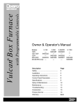
1
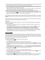
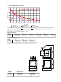
Air Exchange with Programmable Controls
Vulcan Box Furnace
Owner & Operator's Manual
Models:
3-550A
9493985
230V
3-1750A
9493990
Description
Safety ...............................................
Features ...........................................
Applications ......................................
Installation ........................................
Operating Instructions.......................
Control Panel Description .................
Specifications ...................................
Setup & Maintenance .......................
Troubleshooting ................................
Accessories ......................................
Product Service ................................
Warranty ...........................................
1
Page
2
3
3
4
5
9
10
12
14
15
15
Back
FEATURES
• High Performance Hybrid Muffle
•
•
•
•
•
•
•
Longer life and more durable than fiber
Faster heating and faster cooling than firebrick
Wide operating temperature range
50°C (122°F) --- 1100°C (2012°F)
Smooth, low force vertical lift door, with roll back action
Gives maximum access with minimum vertical space
Programmable air exchange using preheated makeup air and Venturi exhaust (ASTM D3174).
Programmable controller with 9 three stage programs (6 segments each) and 1 program with a single
temperature hold
Heavy duty construction with stainless steel front panel
Delay Start operation that enables the user to program the cycle completion time rather than calculating
the start time
Easy to operate and program with user friendly graphic interface
• Programs linkable for 6 stage operation
• Integrated door safety switch breaks both sides of the power line to muffle
• Wide programmable linear temperature rates both positive and negative (0.1 to 40°C/minute)
• Easy / Lower Cost Muffle Service
Individual muffle heating plate replacement
APPLICATIONS
•
•
•
•
MATERIAL ASHING
MATERIAL OXIDIZING
WAX BURNOUT
MATERIAL HEAT TREATING
3
INSTALLATION INSTRUCTIONS
UNPACKING CAUTIONS:
Carefully unpack and remove the furnace from its shipping carton. Save the carton and other packing
material for future use in transporting the furnace.
The furnace shipping carton contains the following:
• One furnace complete w/ power cord
• Owner's & Operator's Manual
• Ceramic floor tray (shipped in the muffle)
• Muffle shelf (Model 1750 only)
Shipping damage should be reported to the carrier as soon as detected.
LIFTING AND CARRYING:
NOTE: The 1750A models require two people to handle the furnace.
1. Get a firm footing. Keep your feet, shoulder width apart for a stable base.
2. Bend your knees. Don't bend at the waist.
3. Grip the base of the furnace and lift with your legs.
4. Keep the load close to your body and carry the unit to the destination. Keep your back upright during lifting.
INSTALLATION:
1. Remove all packing material from in and around the furnace. The furnace should be located at least 15cm (6")
away from walls, shelves, and heat sensitive materials. Open the furnace door and remove the packing material
from inside the furnace. NOTE: The furnace front panel may show some discoloration around the muffle due
to the calibration and "burn-in cycles" performed at the factory.
2. The furnace should not be located directly under shelves and other airflow restrictions.
3. On high voltage, 230V units, connect the power cord to the socket in rear of furnace (this applies to 550A only,
1750A cord is already connected).
4. Positioning the furnace:
a) (Combustion, Burnout or Reaction Processes) Position the furnace under a vent hood or connect the exhaust
vent to a ventilation system to prevent exposure to the exhaust fumes.
b) (Heat Treating or Non-Reaction Processes) Position the furnace under a vent hood. The ventilation system
should accept a minimal of 25 CFM.
5. Connect the furnace to a power circuit or receptacle with an overcurrent protection (circuit breaker or fuse) rating
of 10 Amps. This circuit should only supply the furnace. The 1750 North American model requires a 20A supply
(breaker/receptacle).
6. Turn on the green power switch (right-hand side of the control panel) and the LCD display will come on. The
light in the green power switch lights when the door is closed and the start key is pressed.
7. At this time, your new furnace should be ready to operate. Please review the OPERATIONS and SETUP &
MAINTENANCE sections of the manual before proceeding to select special options.
4
OPERATIONS
RUNNING A PROGRAM:
The furnace has 9 three stage programs and one single temperature hold program. The furnace is sold with
the program parameters set to the factory defaults which can be used for testing. First time operation will
require the user to enter their desired parameters into one of these programs.
1. Turn on green power switch (right-hand side of control panel)
After a short delay for internal testing, the furnace will display approximate room temperature, program
time (hours:minutes), and program number. All red LEDs are off. (If any of the LEDs are on, the furnace
was already running a program when it was last turned off.)
2. Select or change the program to the desired number by pressing the digit key (1-9) for the desired program
followed by the ENTER
key. The display will be updated to show the new program number and its
approximate run time.
3. Pressing the green Start S key will start this program. The red LEDs will come on and the time will start
to count down. The green power switch will light when the door is closed. The LEDs will turn off as each
segment of each stage of the program is completed.
• During program operation, the total program cycle time is counting down as indicated by the flashing
colon.
• If a program is started when the muffle is already heated, the furnace will heat or cool at the first ramp
rate to reach the first temperature segment. The total cycle time will be updated once the start key has
been pressed.
• The program will end by maintaining the last muffle temperature, displaying "Hold", beeping every 3
seconds and flashing the last Temp LED. See information on End Of Program options (point 1) in the
"Setup & Maintenance" section if other end of cycle operations are preferred.
4. Pressing the °C / °F key will change the temperature display from °C to °F and back. This key is not active
during parameter programming.
5. A short power outage during the operation of a program will not terminate or abort the program unless the
muffle temperature drops more than 32°C (58°F). If the power outage occurs when the muffle temperature
is close to, or at room temperature (e.g. during Delay Start operation) the furnace will continue the program
when power is restored regardless of the temperature drop or the amount of time that has expired.
6. Pressing the Escape ESC key cancels beeping at the end of a program. It also will return the furnace to a
display of the current conditions during programming operations.
7. Opening the door during a cycle interrupts power to the heating elements.
STOPPING A PROGRAM:
1. Pressing the red Stop S key will stop the program that is currently running. The red LEDs will go out
and the display will show the current program number, approximate cycle time, and the current muffle
temperature.
PROGRAMMING:
The furnace increases productivity and reliability for the operator because cycles or programs can be
preprogrammed and operated automatically. Once programmed, the parameters are retained in memory even
with the loss of power. Parameters are not retained in memory if entered during the operation of a program
(experimental operation).
Each program is made up of 3 stages which contain 3 parameters each. The parameters are grouped into
ramp rates (R1, R2, R3), temperatures (T1, T2, T3), and dwell or hold times (H1, H2, H3). The 1,2,3 indicates
the stage number or sequence. The temperatures can be programmed in either °C or °F; the ramp rates in °C
per minute or °F per minute; and the hold times in hours and minutes (hh:mm).
5
RAMP RATES (R) (0 - 40°C/minute)
1. Pressing the Rate
key display's the current value of the R1 parameter followed by 3 blanks for a new
value.
• For example: R1 8.0°C/M ->_ _ _
• The corresponding LED will also light to indicate the selected stage and parameter.
2. Use the digit keys (0,1,2,...,9) to enter the desired parameter value followed by the ENTER
key. The
new parameter is now stored in memory.
• If a value is entered that is out of the acceptable range, the furnace will beep and display the acceptable
range.
• Programming a Rate to 0 will cause the furnace to terminate the remainder of the program stages. For
example, if R2 is set to 0 then at the end of the first hold time (H1) the furnace will end the program,
making the program a single stage.
key additional times gives access to the Rate parameters for the other two stages.
3. Pressing the Rate
The 4th time the key is pressed the display circulates back to the beginning and the R1 parameter will be
displayed again.
• The Rate
key operates the same if pressed during the operation of a program with the following
exception. The new Rate entered is used only for that one program or cycle and not stored in memory.
• Negative ramp rates are also possible if slower than natural cooling.
TEMPERATURES (T) (50 - 1100°C or Tmax)
1. Pressing the Temp
key makes the display show the current value of the T1 parameter followed by 4
blanks for a new value.
• For example: T1 160°C ->_ _ _ _
• The corresponding LED will also light to indicate the selected stage and parameter.
2. Use the digit keys (0,1,2,...,9) to enter the desired parameter value followed by the ENTER
key. The
new parameter is now stored in memory.
• If a value is entered that is out of the acceptable range the furnace will beep and display the acceptable
range.
3. Pressing the Temp
key additional times will display and give access to the Temp parameters for the
other two stages. The 4th time the key is pressed the display circulates back to the beginning and the T1
parameter will be displayed again.
• The Temp
key operates the same if pressed during the operation of a program with the following
exception. Any new parameter entered is used only for that one program or cycle and not stored in
memory.
R
R
R
T
T
T
HOLD TIMES (H) (0 - 99:59 mm:ss)
1. Pressing the Hold
key display's the current value of the H1 parameter followed by 4 blanks for a new
value.
• For example: H1 1:00H ->_ _ : _ _ (1 hours and 00 minutes)
• The corresponding LED will also light to indicate the selected stage and parameter.
2. Use the digit keys (0,1,2,...,9) to enter the desired parameter value up to 99 minutes and 59 seconds
followed by the ENTER
key. The new parameter is now stored in memory.
3. Pressing the Hold
key additional times gives access to the Hold parameters for the other two stages.
The 4th time the key is pressed the display circulates back to the beginning and the H1 parameter will be
displayed again.
• The Hold
key operates the same if pressed during the operation of a program with the following
exception. Any new parameter entered is used only for that one program or cycle and not stored in
memory.
H
H
H
A
AIR EXCHANGE OPERATION
1. The air exchange operation is accomplished by using the venturi principle to draw air out of the muffle and into
an exhaust air flow. The hot muffle air does not pass through the fan. Make up air for the muffle is introduced
behind the muffle heating plates. This indirect air path causes the make up air to preheat before it reaches
the muffle cavity to assure temperature uniformity.
6
2. The air exchange fan produces about 20CFM of flow when operated at full speed. The vent hood or system being
used for the furnace should have sufficient capacity to accommodate this airflow.
3. The air exchange operation may be controlled for 10 different settings, ranging from 0 to 9 (off to full on). The
maximum setting of 9 on the control performs approximate 5 air exchanges per minute. The curves shown on
page 13 show approximate air changes vs. fan setting.
Example: Stage 1 of program 5 can be programmed to a fan setting of 9 while stage 2 of program 5 can be
programmed to a fan setting of 3 and stage 3 of program 5 to a fan setting of 0 (off).
4. The air control settings are retained in memory for each program even when the power is removed.
5. The air control settings are programmed into memory the same way as other parameters. Change to the program
number of interest, press the
key: once for stage 1, twice for stage 2 and three times for stage 3. The
display shows the current fan level and a new level may be programmed.
A
A fan speed setting is changed and stored by pressing a digit key (0-9) followed by the ENTER key. A fan setting
change made while a program is operating (running) is only used during that cycle and is not saved in permanent
memory.
The higher the air control setting the slower the furnace will heat. High air control settings with low line voltages
may prevent the furnace from reaching the maximum temperature.
PROGRAM 0
Program 0 is a single temperature hold program. The furnace will heat to this temperature and maintain it as
long as power is applied.
1. Press the 0 key. The display shows the current programmed temperature and the 0 program number.
2. For example: T0 100°C -> _ _ _ _
3. Use the digit keys (0,1,2,...9) to enter the desired temperature followed by the ENTER
key. The
new parameter is now stored in memory. The display shows: 100°C ***** 0 where 100 is the current
muffle temperature, 0 the program number, and ***** indicates that the program is not running.
4. Pressing the Start S key causes the furnace to heat at full power to the programmed temperature.
The display shows "xxxx°C *Hold* 0" "xxxx" is the current muffle temperature, the word "Hold" indicates
single stage operation and 0 indicates the program number. The T1 LED will also be on.
SPECIAL FEATURES
DELAY START (D)
The Delay Start function automatically starts a program so that it is completed at a selected time up to 7 days later.
The delay is programmed in terms of delay days and completion time. A clock is used to keep track of time as long
as the power switch is on. If a power outage should occur during a "Delay Start", the completion time will be delayed
by the length of time the power was off (the clock stopped running).
Programming The Delay Start:
key shows the time of day and beep.
1. Pressing the Delay Start
• For example: Now=7:30->_ _:_ _
• The corresponding LED will also light to indicate the Delay Start is selected.
2. Use the digit keys (0,1,2,...,9) to enter the current time of day followed by the ENTER
key. The new
parameter is now stored in memory. The time of day is entered as a 24 hour clock (11:34PM is 23:34), (8:10AM
is 08:10).
• Programming the current clock time "Now = 7:30 -> _ _:_ _" is only displayed and requested if there has been
a power outage since the last time the Delay Start was operated. Turning the power switch off stops the clock.
3. Pressing the Delay Start
key again shows the Delay D parameter in days.
• For example: Day: 1 [1,2,...,7]
• The corresponding LED will also light to indicate the Delay Start is selected.
4. Use the digit keys (0,1,2,...,7) to enter the desired number of delay days followed by the ENTER
key. The
new parameter is now stored in memory.
• If a value is entered that is greater than 7, the furnace will display and use 7.
5. Pressing the Delay Start
key again displays the desired program completion time. The furnace will calculate
the approximate time that the program needs to start so that it is completed at this programmed time.
D
D
D
7
• For example: End = 14:30 -> _ _ :_ _
• The computer uses a 24 hour clock. Therefore, the completion time will be 2:30 PM.
6. Pressing the Delay Start
key again shows the actual time (Now).
• Pressing the key additional times will cycle through the other parameters. Press the Escape
the function.
D
ESC
key to stop
Running A Delay Start Program:
1. Select the desired program number (See previous section on RUNNING A PROGRAM)
key to display the delay days.
2. Press the Delay Start
3. Press the green start S key to start the delay timer.
- The corresponding LED will also light to indicate the Delay Start is selected.
- If the program run time is longer than the specified delay time the furnace will skip the delay and start the program
immediately.
D
LINKING PROGRAMS
Programs can automatically run in sequence by using the Linking feature. With this method, a 6 stage (12 segment)
program can be run automatically. Additional programs can also be linked as each program is completed.
Running Linked Programs:
1. Press the green Start S key with the first program to be run. The furnace will start operation.
2. Use the digit keys (1,2,...,9) to enter the next program number to be run followed by the ENTER
key. The
furnace will now run the first program followed automatically by the second. The program cycle time on the
display will be the combination of the two programs. The display will alternately show the first program number
and then the second program number.
8
CONTROL PANEL DESCRIPTION
°C / °F
changes the
temperature
from °C to °F
and back. This
key is not
active when
viewing
parameters.
LCD Display displays
the furnace muffle
temperature, program
count down time, and
program number. During
parameter programming
the display shows the
current value and new
value for confirmation. It
signals program operation
by flashing the colon in the
program time.
Temp
Rate key displays the
current program's heat
rates in degrees per
minute. Press once for R1
(rate 1), twice for R2 (rate
2), and three times for R3
(rate 3). The corresponding LED lights and the
current value is displayed.
New parameter values can
be stored in memory at this
time followed by the
ENTER key.
Time
Green START key
starts current program.
Red STOP key stops
or aborts program if
already operating. The
red LEDs turn on when
the cycle is started and
are turned off as the
program is completed.
The display counts down
the time remaining in the
program during
operation.
cancels or aborts
parameter programming
by returning the control to
the current conditions
display. The display
shows the current muffle
temperature, program
number, and program time
or time remaining. This
key also cancels the
beeping at the end of the
program.
S
S
Start
Stop
Prog
1100°C 12:30H 1
°C / °F
ESC (Escape) key
ESC
1
2
3
R
4
5
6
T
7
8
9
H
0
A
D
Enter
Air Control
DELAY START
activates the air
exchange feature for
a chosen stage
during a firing cycle.
Press once for S1
(stage 1), twice for
S2 (stage 2) and
three times for S3
(stage 3). Press
ENTER to stage new
value. A setting of 0
means fan is off. A
setting of 9 means
maximum air
exchange.
activates the function that
allows the furnace to
automatically turn on at a
later time and run a
program. The delay time
is programmed in the
number of days and the
time when the program is
to be finished. The time
is based on a 24 hour
clock. Press this key
once followed by the Start
key to activate or start a
delayed program and the
LED will be turned on.
Press this key several
times to change the delay
parameters.
Program Parameter LEDs indicate
which parameters are
activated and then
completed as the
program is running.
All LEDs are turned on
initially and then
turned off as completed. During
parameter programming the LED lights to
indicate which
parameter is currently
selected. The LEDs do
not light if a particular
stage is turned off
during that cycle.
9
Temperature
Hold time key
Digit Keys
key displays the
current program's
temperatures in
degrees. Press
once for T1 (temp
1), twice for T2
(temp 2), and three
times for T3 (temp
3). The corresponding LED
lights and the
current value is
displayed. New
parameter values
can be stored in
memory at this
time followed by
the ENTER key.
displays the
current program's
hold times in hours
and minutes
(hh:mm). Press
once for H1 (hold
1), twice for H2
(hold 2), and three
times for H3 (hold
3). The corresponding LED
lights and the
current value are
displayed. New
parameter values
can be stored in
memory at this
time followed by
the ENTER key.
are used to
CHANGE
PROGRAMS
and enter new
program
parameters.
ENTER key is
used to store
new program
number or
parameter in
memory.
SPECIFICATIONS
PARAMETER
- Temperature Range: 50°C (122°F) - 1100°C (2012°F) / 1° Resolution
- Hold Time Range: 0:00 - 99:59 (hours:minutes) / 1 Min Resolution
- Ramp Rate Range: 0 - 40°C / minute (72°F) / 0.1°C Resolution
- Temperature Accuracy: ± 5°C (± 9°F) at steady state
- Muffle Temperature Uniformity: ± 8°C (± 15°F) at steady state
ELECTRICAL
Voltage Nominal:
Voltage Range:
@ 50/60Hz
3-550A
230V
200-240V
Steady State
Current:
Amps @ 230V
3-1750A
230V
200-240V
9.6A
19.0A
2204W
4370W
Watts to Maintain 1000°C: 1050W
2200W
Max Power Watts:
(Air Exchange setting @ 0)
ENVIRONMENTAL
Ambient Operating Temperature: 5 - 40°C
Relative Humidity: Maximum 80%, non-condensing
3-550A PERFORMANCE CURVES
1200
1200
1000
Temperature (°C)
Temperature ( °C )
1000
800
800
600
600
400
400
200
200
00
00
10
10
20
20
30
30
Heat Fan = 0
Cool Down Fan = 1
40
40
50
50
60
60
Time (min.)
Cool Down Fan = 0
* Heat Up Fan = 9
70
70
80
80
90
90
100
110
100
110
Heat Up =1
Cool Down Fan = 9
10
3-1750A PERFORMANCE CURVES
1200
1200
Temperature (°C)
1000
1000
800
800
600
600
400
400
200
200
00
00
20
20
40
40
60
60
Heat Fan = 0
Cool Down Fan = 1
80
80
100
100
120
120
140
140
Time (min.)
TIME(min.)
Cool Down Fan = 0
* Heat Up Fan = 9
160
160
180
180
200
200
Heat Up =1
Cool Down Fan = 9
Test Conditions: Nominal line voltage, no load in the muffle only floor tray, full power applied to the muffle for the Heating Curve. The
programmable rates are linear and fall below the heating curve and above the cooling curve (door closed) for some selections.
MECHANICAL OUTLINE DRAWING: mm(in)
Exterior Dimensions:
Model:
A
B
3-550A
3-1750A
635mm(25.0")
807mm(31.8")
430mm(17.0")
541(21.3")
C
400mm(15.8")
572mm(22.5")
Internal Muffle Dimensions:
Model:
3-550A
3-1750A
G
H
I
180mm(7.0")
230mm(9.0")
230mm(9.0")
274mm(10.8") 363mm(14.3") 325mm(12.8")
Model
Furnace Weight:
Shipping Weight:
3-550A
3-1750A
23kg(51lbs)
45kg(100lbs)
28kg(62lbs)
67kg(148lbs)
11
D
489mm(19.3")
584mm(23.0")
E
100mm(4.0")
100mm(4.0")
F
57mm(2.3")
51mm(2.0")
SETUP & MAINTENANCE
SETUP:
The Vulcan furnace goes through a self test that lasts approx. 6 seconds each time power is applied. After this test,
the display will show the word "Setup?" for approximately 5 seconds. In the Setup mode, several different options are
available for the user to select.
The first is the END OF PROGRAM operation which allows the user to select how the furnace should operate at the end
of the program. The second is the Tmax parameter, a temperature alarm that can be programmed into the furnace.
The last is TEMPERATURE ADJUSTMENT CALIBRATION (Tcal) which allows the user to alter the furnace temperature
calibration.
1) Turn on power to the furnace. Press the ENTER
key after the word "Setup?" is displayed and access to
the Setup mode is gained.
The END OF PROGRAM option is now displayed as "Hold = (1), (2),(3)". The (1) option is the factory default.
It instructs the furnace to control the last programmed temperature, display "Hold" and beep every 3 seconds
until the red Stop S key is pressed. Pressing the Escape ESC key will only stop the beeping.
The (2) option instructs the furnace to control the last programmed temperature, and display "Hold" but without
beeping until the red Stop S key is pressed.
The (3) option instructs the furnace to turn the control off and let the muffle cool to room temperature. The
display shows "End". The Stop key does not have to be pressed.
Use the digit keys (1,2,3) to change the END OF PROGRAM option.
key when the desired END OF PROGRAM is selected will store the entry into
2) Pressing the ENTER
memory and then advance to Tmax the next option. The Tmax value limits the maximum temperatures that
the furnace may be programmed to. The factory setting for Tmax is 1100°C. Use the digit keys (0,1,2,...,9) to
enter the desired Tmax value followed by the ENTER
key. The new Maximum Temperature is now
stored in memory and the next option is displayed.
3) The final option is the temperature adjustment calibration displayed as "Tcal 1000°C->_ _:_ _". The factory
setting for Tcal is 1000°C. Use the digit keys (0,1,2,...,9) to enter the desired Tcal value followed by the
ENTER
key. The new Temperature Calibration is now stored in memory. Entering a 1000 will return
the furnace to the factory calibration. See the next section on Temperature Adjustment Calibration for
specifics on how to determine a new adjustment number.
TEMPERATURE ADJUSTMENT CALIBRATION:
Every VULCAN furnace is calibrated in the factory at 1000°C. Under normal use the furnace should not require
calibration. The electronics used in the VULCAN furnaces are very stable and will have minimal drifts over the life
of the furnace. Thermocouple replacement could be a potential requirement for calibration if high accuracy is
required.
This calibration can be altered by entering a new Tcal value in the Setup mode listed previously. The Tcal value
has a range of 900 to 1100°C.
Example 1:
A program is operating at a steady temperature of 875°C and a separate thermocouple is inserted in the furnace
and a digital thermometer is used to measure the muffle temperature. The display shows 875°C (the programmed
temperature) but the digital thermometer reads 868°C. A new calibration value is calculated by dividing the
displayed temperature (furnace) by the measured temperature (digital thermometer), the result is multiplied by the
current Tcal value (factory default is 1000°C). In this case (875/868 = 1.008; 1.008 * 1000 = 1008). 1008 is now
entered in as the Tcal value. With this method a furnace calibration can be done at any operating temperature.
Example 2:
Programmed temperature is 1050°C and the digital thermometer reads 1065°C. The previous Tcal value is 985°C.
(1050/1065 = 0.986 then 0.986 * 985 = 971)
971 should be entered as the new Tcal value.
CLEANING:
- Vacuum dust and dirt from the furnace rather than attempting to blow the dust off. This will minimize the amount
of air born particles.
- Use a soft damp cloth to clean the control panel. Avoid excess water or solution when cleaning the furnace. These
solutions can attack the panel or electronics and cause the furnace to malfunction.
12
TROUBLESHOOTING
ERROR CODES:
Err codes can be cleared from the display by turning the front panel power switch off and then on again.
Code
Description
Err 1
Over Temperature
Err 2
Open Thermocouple
Err 3
Temp > Tmax
Possible Cause
Temp > 1120°C, shorted thermocouple, shorted triac, shorted optotriac,
wiring connections, computer PCB
Open TC tip, connection to TC, TC to (TC) PCB connection, computer PCB
Muffle temperature has exceeded the programmed limit temperature TMAX
(see SETUP?).
Err 7
Brown-out
Low line voltage < 90VAC (<190VAC for 200-240V), wall socket shared with
other loads, furnace connected with small extension cord
Err 8
EEPROM error
Parameter program memory error; computer PCB
Err 19
Line frequency
No line frequency detected, computer PCB
13
TROUBLESHOOTING THE VULCAN "3-" CONTROL
PROBLEM
Dead, Not Operating
No Power / Display
CHECK LIST / CAUSES
- Check power receptacle or outlet for power
- Check line or power cord connections
- Turn on green power switch
Not Heating
During Program
Operation
Does the green power switch light when the Start key is pressed?
No: - Is door completely closed? Door switch may be interrupting power.
Yes: - Check the fuses on the controller PCB
- Check heating element plates for continuity
Door Too Loose or
Tight
- The amount of force or drag on the door movement can be changed by adjusting the
hex screws located on the upper rear corners of the furnace cabinet. Turning the
screw clockwise adds drag and requires more force
Heating Too Slow
- Rate programmed wrong. 1.5°/minute rather than 15.0°/minute
- Large loads will slow down response time and increase the time to temperature by 2
to 5 times
Program Turns Off
Too Early
- Programming a Rate to zero will terminate the remainder of the program
- End of program option has been changed from 1 or 2 to option 3 which turns off the
furnace at the end of the program [End].
Fan Does Not Operate - Operates only in a start cycle
- Setting of 0 means no fan active
14
ACCESSORIES
DESCRIPTION
PART NUMBER
Tongs; 25cm (10") Stainless Steel
Tongs; 30cm (12") Stainless Steel
Tongs; 36 cm (14") Plated Steel
Tray- Bottom, Model 550
Tray- Bottom, Model 1750
Shelf - free standing, Model 550
Shelf - Model 1750
Muffle Hardening Agent
Temperature Pellets, Bottle of 25
705 °C (1300 °F)
815 °C (1500 °F)
9390014
9390015
9491010B
9353057
9353060
9493327
9493396
9491006
Service Manual, Vulcan
9363049
9490911
9490912A
PRODUCT SERVICE
Three methods of product service are available for the VULCAN. The first method is telephone assistance, available
at the numbers listed below. The second is to return the furnace for servicing using the instructions below. The final
method is to call DENTSPLY Neytech at the phone numbers below and obtain a service manual for a nominal fee.
BEFORE RETURNING THE FURNACE, DO THE FOLLOWING:
1. Remove all firing trays, shelves and other loose items from inside the muffle. Pack the muffle with the original foam
block or newspapers to prevent shipping damage to the heating plates.
2. The original packing material should be used for the return shipment. Contact DENTSPLY Neytech for replacements if they are not available.
3. Call DENTSPLY Neytech for a RMA number (Return Material Authorization). This is used to track and identify your
furnace. Material received without this number may not be identifiable.
4. Equipment damaged in shipment as the result of improper packing may not be repaired at the expense of the
carrier. DENTSPLY Neytech. will not be responsible for damages resulting from improper packing.
Ship Prepaid To:
909-795-2461
FAX 909-795-5268
DENTSPLY Neytech
RMA Number __________
13553 Calimesa Blvd.
Yucaipa, CA 92399-2398 USA
19
15
WARRANTY
WARRANTY: Except with respect to those component parts and uses which are herein after
described, DENTSPLY Neytech warrants this furnace to be free from defects in material and
workmanship for a period of two years from the date of sale. DENTSPLY Neytech’s liability
under this warranty is limited solely to repairing or, at DENTSPLY Neytech’s option, replacing
those products included within the warranty which are returned to DENTSPLY Neytech within the
applicable warranty period (with shipping charges prepaid), and which are determined by
DENTSPLY Neytech to be defective. This warranty shall not apply to any product which has
been subject to misuse; negligence; or accident; or misapplied; or modified; or repaired by
unauthorized persons; or improperly installed.
INSPECTION: Buyer shall inspect the product upon receipt. The buyer shall notify DENTSPLY
Neytech in writing of any claims of defects in material and workmanship within thirty days after
the buyer discovers or should have discovered the facts upon which such a claim is based.
Failure of the buyer to give written notice of such a claim within this time period shall be deemed
to be a waiver of such claim.
DISCLAIMER: The provisions herein state DENTSPLY Neytech's sole obligations and exclude
all other remedies or warranties, expressed or implied, including those related to MERCHANTABILITY and FITNESS FOR A PARTICULAR PURPOSE.
LIMITATION OF LIABILITY: Under no circumstances shall DENTSPLY Neytech be liable to the
buyer for any incidental, consequential or special damages, losses or expenses.
LIMITATION OF ACTIONS: The buyer must initiate any action with respect to claims under the
warranty described in the first paragraph within one year after the cause of action has accrued.
Air Exch 0150 93-63-092
16