1
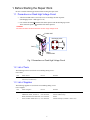
SAFETY PRECAUTIONS
The following precautions should be observed when servicing.
1.
Since many parts in the unit have special safety-related characteristics, always use genuine CANON replacement parts.
Especially critical parts in the power circuit block should not be replaced with other makes.
2.
Critical parts are marked with ! in the schematic diagrams.
When servicing, observe the original lead dress. If a short circuit is found, replace all parts which have been overheated or damaged
3.
by the short circuit.
After servicing, see to it that all the protective devices such as insulation barriers, insulation papers shields are properly installed.
4.
After servicing, make the following leakage current checks to prevent the customer from being exposed to shock hazards.
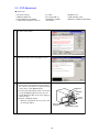
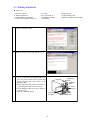
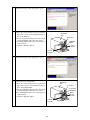
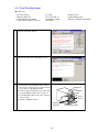
4-1 Leakage Current Cold Check
1) Unplug the AC cord and connect a jumper between the two prongs on the plug.
2) Measure the resistance value, with an ohmmeter, between the jumpered AC plug and each exposed metallic cabinet part
on the equipment such as screwheads, connectors, control shafts, etc. When the exposed metallic part has a return path to
the chassis, the reading should be between 1MΩ and 5.2MΩ. When the exposed metal does not have a return path to the
chassis, the reading must be ∞.
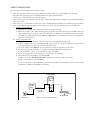
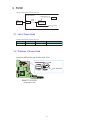
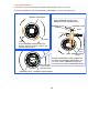
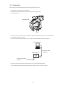
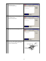
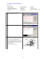
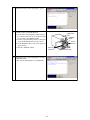
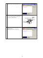
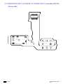
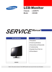
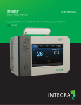
4-2 Leakage Current Hot Check
1) Plug the AC cord directly into the AC outlet. Do not use an isolation transformer for this check.
2) Connect a 1.5KΩ 10 watt resistor, paralleled by 0.15µF capacitor, between each exposed metallic parts on the unit and a
good earth ground such as a water pipe, as shown in the figure below.
3) Use an AC voltmeter, with 1000Ω/volt or more sensitivity, to measure the potential across the resistor.
4) Check all exposed metallic parts of the cover (Cable connection, Handle bracket, metallic cabinet.
Screwheads, Metallic overlays, etc), and measure the voltage at each point.
5) Reverse the AC plug in the AC outlet and repeat each of the above measurements.
6) The potential at any point should not exceed 0.75V RMS.
A leakage current tester (FLUKE MODEL : 8000A equivalent) may be used to make the hot checks.
Leakage current must not exceed 0.5 milliamp.
In case a measurement is outside of the limits specified, there is a possibility of a shock hazard, and corrective action must
be taken before returning the instrument to the customer.
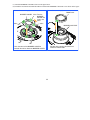
AC VOLTMETER
DEVICE
UNDER
TEST
Test all
exposed
metal parts
1.5KΩ
0.15µF
Water pipe
(Earth Ground)
AC OUTLET
Figure. 1 Leakage Current Hot Check
R2: CONFIDENTIAL
GENERAL DESCRIPTION
OF PRODUCT
Trademarks:
Canon Inc.'s trademark, logos, product names, service marks and those trademark, logos, product names,
service marks licensed to Canon Inc. by any of its affiliate or subsidiary are registered or unregistered
marks of Canon Inc. or such affiliate or subsidiary in Japan and/or other countries.
Adobe, the Adobe logo, Acrobat, the Acrobat logo and Reader are either registered trademarks or trademarks of Adobe Systems Incorporated in the United States of America and/or other countries.
All other trademarks, product names, service marks are generally either registered or unregistered marks
of their respective owners.
Copyright:
All copyrights in the content of this Service Manual are owned or controlled by Canon Inc. You are not
permitted to copy, reproduce, download, modify, adapt or translate in any way the content of this Service
Manual for any purpose other than the purpose contemplated herein without prior written consent of
Canon Inc.
* The “IXY DIGITAL 90/10” product designation used in this document refers to the IXY DIGITAL 90/10, but
marketing departments in other resions use DIGITAL IXUS 75/70 or PowerShot SD750/SD100 DIGITAL ELPH to
refer to the same product.
CONTENTS
1
2
3
4
Overview
1-1
Summary of Main Features . . . . . . . . . . . . . . . . . . . . . . . . . . . . . . . . . . . . . . . . . . . . . . . . . 1
1-2
Comparison of Main Features . . . . . . . . . . . . . . . . . . . . . . . . . . . . . . . . . . . . . . . . . . . . . . . 4
Exterior
2-1
Exterior Photos . . . . . . . . . . . . . . . . . . . . . . . . . . . . . . . . . . . . . . . . . . . . . . . . . . . . . . . . . . . 6
2-2
6-view Diagram . . . . . . . . . . . . . . . . . . . . . . . . . . . . . . . . . . . . . . . . . . . . . . . . . . . . . . . . . . 7
2-3
Nomenclature . . . . . . . . . . . . . . . . . . . . . . . . . . . . . . . . . . . . . . . . . . . . . . . . . . . . . . . . . . . . 9
Specifications
3-1
Product Specifications . . . . . . . . . . . . . . . . . . . . . . . . . . . . . . . . . . . . . . . . . . . . . . . . . . . . 11
3-2
System Diagram . . . . . . . . . . . . . . . . . . . . . . . . . . . . . . . . . . . . . . . . . . . . . . . . . . . . . . . . . 21
3-3
Shooting/Setting Features List . . . . . . . . . . . . . . . . . . . . . . . . . . . . . . . . . . . . . . . . . . . . . . 23
3-4
Direct Print . . . . . . . . . . . . . . . . . . . . . . . . . . . . . . . . . . . . . . . . . . . . . . . . . . . . . . . . . . . . . 24
3-5
Playback Compatibility . . . . . . . . . . . . . . . . . . . . . . . . . . . . . . . . . . . . . . . . . . . . . . . . . . . 27
3-6
List of Accessory and Its Compatibility. . . . . . . . . . . . . . . . . . . . . . . . . . . . . . . . . . . . . . . 29
Accessory Specifications
4-1
Waterproof Case. . . . . . . . . . . . . . . . . . . . . . . . . . . . . . . . . . . . . . . . . . . . . . . . . . . . . . . . . 33
4-2
Main Unchanged Accessories . . . . . . . . . . . . . . . . . . . . . . . . . . . . . . . . . . . . . . . . . . . . . . 36
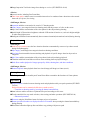
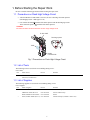
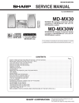
1 Overview
Highly anticipated successor models to IXY DIGITAL 80/70 offer even better
image quality and performance thanks to DIGIC III, while featuring large
LCD monitors and sophisticated slim design
(IXY DIGITAL 10: 2.5
inch type)
(IXY DIGITAL
90 only)
1-1 Summary of Main Features
Text highlighted in red: New features introduced with the IXY DIGITAL 90/10, Text highlighted in blue: Differences from the IXY
DIGITAL 80/70
High Image Quality
DIGIC III imaging processor provides improved image quality and functionality
High-resolution 7.1-megapixel CCD supports prints up to A3 size
3x optical zoom lens support a wide range of shooting scenes
• 35 – 105 mm (35mm film equivalent), f/2.8 (W) / f/4.9 (T)
High ISO Auto and super high ISO-speed 1600 significantly reduce camera shake and subject blur
iSAPS technology enables high-speed AF and high-definition AE/AWB
Full Featured and Easy Operation
Shooting Features
<Still Images>
Face detection function
• Face Detect AF focuses the faces in the screen
• Face Detect AE incorporates face brightness
• Face Detect FE controls the flash output for getting optimum face brightness during flash photography
Selected ISO speed is displayed on the LCD monitor
• Effective speed is displayed when pressing the shutter button halfway while Auto or High ISO Auto
is selected
• The raised ISO speed in 1/3-stop increments is displayed when using the Auto ISO shift
Auto ISO shift increases ISO speed to shutter speed without camera shake with just one push
Night Display automatically brightens images on the LCD monitor during sunset and evening shooting
Safety zoom enables active use of digital zoom ranges where image quality is not reduced
Digital tele-converter easily achives a tele-converter function
1
Image Inspection Tool checks image focus during rec. review (IXY DIGITAL 90/10)
<Movies>
6 movie modes, including Fast Frame Rate
Time Lapse movie enables a movie recorded at intervals to be condensed into a short time at the normal
frame rate (15 fps/sec) for viewing
<Still Images, Movies>
Aquarium added to scene modes for a total of 17 shooting modes
Auto Category sets categories based on shooting mode and the presence of a face on the screen
My Colors enables customization of the color palette for the subject during shooting
Quick-bright LCD maximizes brightness when the LCD monitor is hard to see, such as in bright sunlight
or other strong light sources
Intelligent Orientation Sensor automatically detects camera orientation (horizontal and vertical) during shooting
Playback Features
<Still Images>
Auto red-eye correction uses the face detection function to automatically correct red-eye that occurred
during flash photography
My Category sorts images into categories based on shooting conditions
New Jump function enables instant switching and playback of specific images based on keywords or
categories
My Colors enables customization of the color palette for the subject during playback
Transition adds fade-in and fade-out effects when switching between playback images
Slide Show enables playback of images grouped by folder, shooting date, and other conditions
<Still Images, Movies>
Resume Playback starts playback from last viewed image (still image) or frame (movie)
Printing Features
PictBridge for superior versatility and Canon Direct Print to maximize the functions of Canon printers
Operability
Playback button switches between shooting mode and playback mode by one-push operation (IXY DIGITAL 90)
Playback button can be customized (slide show, sound recorder)
• Transition to shooting mode by pressing the shutter button halfway
Omni selector enables selection of optimum ISO speed according to each scene
Touch control dial for easy mode selection, value setting, and other operations (IXY DIGITAL 90)
• Enhanced operations
Shortcuts using the Print/Share button for improved ease of operation
Shutter speed and f/number are displayed on the LCD monitor when pressing the shutter button halfway
during shooting
Print/Share button that lights up blue and allows easy printing with just one push
2
Others
The LCD monitor with 3.0-inch size (IXY DIGITAL 90), 2.5-inch size (IXY DIGITAL 10), high resolution (approx. 230,000 pixels), and wide viewing angle
• Protective window enhances sturdiness (IXY DIGITAL 90/10)
Sound recorder capable of up to two hours of audio recording
Low level format maximizes memory card performance
SDHC memory card support for high-volume shooting (both still images and movies)
UI display available in 25 languages*
* Models
for Japanese market available in 2 languages (Japanese and English)
Design
Compact body with even lower profile
New "Edge" design with distinct "Solid Form" and two color variations for circular section (modern
black/futuristic silver) (IXY DIGITAL 90)
Back to basics "Box & Circle" design, and two color variations (Black/Silver) (IXY DIGITAL 10)
3
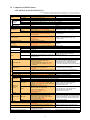
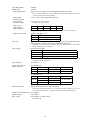
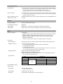
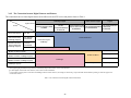
1-2 Comparison of Main Features
• IXY DIGITAL 90 and IXY DIGITAL 80
• Highlighted table items indicate changes from the IXY DIGITAL 80. Text in red shows changes.
Conditions may apply depending on items (for details, see 3-1 Product Specifications).
IXY DIGITAL 90
Lens
Camera Effective Pixels
Image Sensor
(CCD)
Color Filters
Focal Length (35mm film equivalent)
Normal
Focusing
Macro
Range
Digital Macro
Image Stabilizer (IS) System
Imaging Processor
Viewfinder
LCD Monitor
Type
Features
Focus
Metering System
Exposure Compensation
ISO Speed
White Balance
Shutter
Aperture
Type
Speeds
Type
f/number
Modes
Flash
Range
Recording Specifications
Shooting Specifications
Main Features
Shooting Modes
Digital Zoom
My Colors
Continuous Shooting
Number of Images Shot (CIPA)
Recording Media
File Format
Still Images
Data Type
Movies
Audio
Still Images
Number of
Recording
Pixels
Movies
Playback
Specifications
Others
Main Features
Still Images
Movies
Direct Print
Display Languages
Interface
Power Source
Dimensions (excluding protrusions)
Weight (camera body only)
IXY DIGITAL 80
Approx. 7.1 million pixels, 1/2.5-inch type
Approx. 6.0 million pixels, 1/2.5-inch type
Primary color filters (Bayer type)
3x Zoom: 35 (W) – 105 (T) mm
30 cm (12 in.) – infinity
3 – 50 cm (W), 30 – 50 cm (T) (1.2 in. – 1.6 ft. (W), 12 in. – 1.6 ft. (T))
3 – 10 cm (W) (1.2 in. – 3.9 in. (W))
–
DIGIC III
DIGIC II
–
3.0-inch type, color LCD with wide viewing angle
3.0-inch type, color LCD with wide viewing angle
(Effective pixels: Approx. 230,000 pixels)
(Effective pixels: Approx. 173,000 pixels)
Brightness adjustment (15 levels, Quick-bright LCD)
AiAF (Face Detect*1/9-point) / AF (1-point*2)
AiAF (9-point) / AF (1-point*)
*1 If no face is detected, 9 points are used.
* Fixed to center
*2 Fixed to center
*1
*2
Evaluative , Center-weighted average, Spot
*1 Control to incorporate facial brightness in Face
Evaluative, Center-weighted average, Spot*
* Fixed to center
Detect AF.
*2 Fixed to center
±2 stops in 1/3-stop increments
Auto, High ISO Auto, ISO 80/100/200/400/800/1600
Auto, High ISO Auto, ISO 80/100/200/400/800
(Standard Output Sensitivity, Recommended
equivalent
Exposure Index)
Auto, Day Light, Cloudy, Tungsten, Fluorescent, Fluorescent H, Custom
Mechanical shutter and electronic shutter
15 – 1/1500 sec.
Circular type
f/2.8 (W), f/4.9 (T)
Auto, auto with red-eye reduction, flash on with
Auto, on, off
red-eye reduction, on, off, slow synchro
Normal: 50 cm – 3.5 m (W), 50 cm – 2.0 m (T) (1.6 – 11 ft. (W), 1.6 – 6.6 ft. (T))
Macro: 30 – 50 cm (W/T) (12 in. – 1.6 ft. (W/T))
(ISO speed: Auto)
Face Detect FE, FE lock
FE lock
Auto, Camera M (Manual), Digital Macro,
Auto, Camera M (Manual), Digital Macro, Portrait,
Color Accent, Color Swap, Stitch Assist,
Night Snapshot, Scene*, Stitch Assist, Movie
Special Scene*, Movie
* Portrait, Night Snapshot, Kids & Pets, Indoor,
* Kids & Pets, Indoor, Foliage, Snow, Beach,
Foliage, Snow, Beach, Fireworks, Aquarium,
Fireworks, Underwater, Color Accent, Color Swap
Underwater
Still images/Movies: Approx. 4.0x (up to approx. 12x
Still images/Movies: Approx. 4.0x (up to approx. 12x
in combination with the optical zoom)
in combination with the optical zoom)
Safety Zoom
My Colors Off, Vivid, Neutral, Sepia, Black & White, Positive Film, Lighter Skin Tone, Darker Skin Tone,
Vivid Blue, Vivid Green, Vivid Red, Custom
Approx. 1.7 shots/sec. (Large and Fine)
Approx. 2.1 shots/sec. (Large and Fine)
Approx. 210 images
Approx. 160 images
SD memory card, SDHC memory card, MultiMediaCard SD memory card, MultiMediaCard
Design rule for camera file system, DPOF (Version 1.1) compliant
Exif 2.2 (JPEG)
AVI (Image data: Motion JPEG, Audio data: WAVE (Monaural))
Sound memos, sound recorder: WAVE (Monaural)
Sound memos: WAVE (Monaural)
Large: 3072 x 2304, Medium 1: 2592 x 1944,
Large: 2816 x 2112, Medium 1: 2272 x 1704,
Medium 2: 2048 x 1536, Medium 3: 1600 x 1200,
Medium 2: 1600 x 1200, Small: 640 x 480,
Small: 640 x 480, Postcard date imprint: 1600 x 1200, Postcard date imprint: 1600 x 1200,
Widescreen: 3072 x 1728
Widescreen: 2816 x 1584
Standard, Color Accent, Color Swap:
640 x 480 (30/15 fps) / 320 x 240 (30/15 fps),
Standard, Color Accent, Color Swap:
Fast Frame Rate: 320 x 240 (60 fps),
640 x 480 (30/15 fps) / 320 x 240 (30/15 fps),
Compact: 160 x 120 (15 fps),
Fast Frame Rate: 320 x 240 (60 fps),
Time Lapse: 640 x 480 (0.5/1 fps*)
Compact: 160 x 120 (15 fps)
* Plays back at 15 fps.
Sound recorder
–
Index, My Colors, My Category, New Jump,
magnified, advancing and reversing through
Index, My Colors, magnified, advancing and reversing
magnified images, auto rotate, rotate, histogram,
through magnified images, jump, auto rotate, rotate,
sound memos, sound recorder,
histogram, sound memos, slide show (with effects)
slide show (with effects), resume
Special playback, editing, auto rotate, resume
Special playback, editing
PictBridge, Canon Direct Print, Bubble Jet Direct
25 languages (Models for Japanese market available 23 languages
in 2 languages)
USB 2.0 Hi-Speed (mini-B)*, Audio/Video output
USB 2.0 Hi-Speed (mini-B)*, Audio/Video output
* MTP, PTP supported
* PTP supported
Battery Pack NB-4L
AC Adapter Kit ACK-DC10
91.6 x 56.8 x 19.6 mm (3.61 x 2.24 x 0.77 in.)
90.3 x 56.8 x 20.2 mm (3.56 x 2.24 x 0.80 in.)
Approx. 130 g (4.59 oz.)
Approx. 145 g (5.11 oz.)
4
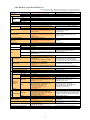
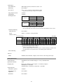
• IXY DIGITAL 10 and IXY DIGITAL 70
• Highlighted table items indicate changes from the IXY DIGITAL 70. Text in red shows changes.
Conditions may apply depending on items (for details, see 3-1 Product Specifications).
IXY DIGITAL 10
Lens
Camera Effective Pixels
Image Sensor
(CCD)
Color Filters
Focal Length (35mm film equivalent)
Normal
Focusing
Macro
Range
Digital Macro
Image Stabilizer (IS) System
Imaging Processor
Viewfinder
LCD Monitor
Type
Features
Focus
Metering System
Exposure Compensation
ISO Speed
White Balance
Shutter
Aperture
Type
Speeds
Type
f/number
Modes
Flash
Range
Recording Specifications
Shooting Specifications
Main Features
Shooting Modes
Digital Zoom
My Colors
Continuous Shooting
Number of Images Shot (CIPA)
Recording Media
File Format
Still Images
Data Type
Movies
Audio
Still Images
Number of
Recording
Pixels
Movies
Playback
Specifications
Others
Main Features
Still Images
Movies
Direct Print
Display Languages
Interface
Power Source
Dimensions (excluding protrusions)
Weight (camera body only)
IXY DIGITAL 70
Approx. 7.1 million pixels, 1/2.5-inch type
Approx. 6.0 million pixels, 1/2.5-inch type
Primary color filters (Bayer type)
3x Zoom: 35 (W) – 105 (T) mm
30 cm (12 in.) – infinity
3 – 50 cm (W), 30 – 50 cm (T) (1.2 in. – 1.6 ft. (W), 12 in. – 1.6 ft. (T))
3 – 10 cm (W) (1.2 – 3.9 in. (W))
–
DIGIC III
DIGIC II
Real-image optical zoom viewfinder
2.5-inch type, color LCD with wide viewing angle
2.5-inch type, color LCD with wide viewing angle
(Effective pixels: Approx. 230,000 pixels)
(Effective pixels: Approx. 173,000 pixels)
Brightness adjustment (15 levels, Quick-bright LCD)
AiAF (Face Detect*1/9-point) / AF (1-point*2)
AiAF (9-point) / AF (1-point*)
*1 If no face is detected, 9 points are used.
* Fixed to center
*2 Fixed to center
Evaluative*1, Center-weighted average, Spot*2
*1 Control to incorporate facial brightness in Face
Evaluative, Center-weighted average, Spot*
* Fixed to center
Detect AF.
*2 Fixed to center
±2 stops in 1/3-stop increments
Auto, High ISO Auto, ISO 80/100/200/400/800/1600
Auto, High ISO Auto, ISO 80/100/200/400/800
(Standard Output Sensitivity, Recommended
equivalent
Exposure Index)
Auto, Day Light, Cloudy, Tungsten, Fluorescent, Fluorescent H, Custom
Mechanical shutter and electronic shutter
15 – 1/1500 sec.
Circular type
f/2.8 (W), f/4.9 (T)
Auto, auto with red-eye reduction, flash on with
Auto, on, off
red-eye reduction, on, off, slow synchro
Normal: 50 cm – 3.5 m (W), 50 cm – 2.0 m (T) (1.6 – 11 ft. (W), 1.6 – 6.6 ft. (T))
Macro: 30 – 50 cm (W/T) (12 in. – 1.6 ft. (W/T))
(ISO speed: Auto)
Face Detect FE, FE lock
FE lock
Auto, Camera M (Manual), Digital Macro, Portrait,
Auto, Camera M (Manual), Digital Macro, Portrait,
Night Snapshot, Color Accent, Color Swap, Scene*,
Night Snapshot, Scene*, Stitch Assist, Movie
Stitch Assist, Movie
* Kids & Pets, Indoor, Foliage, Snow, Beach,
* Kids & Pets, Indoor, Foliage, Snow, Beach,
Fireworks, Underwater, Color Accent, Color Swap
Fireworks, Aquarium, Underwater
Still images/Movies: Approx. 4.0x (up to approx. 12x
Still images/Movies: Approx. 4.0x (up to approx. 12x
in combination with the optical zoom)
in combination with the optical zoom)
Safety Zoom
My Colors Off, Vivid, Neutral, Sepia, Black & White, Positive Film, Lighter Skin Tone, Darker Skin Tone,
Vivid Blue, Vivid Green, Vivid Red, Custom
Approx. 1.7 shots/sec. (Large and Fine)
Approx. 2.1 shots/sec. (Large and Fine)
Approx. 210 images
Approx. 160 images
SD memory card, SDHC memory card, MultiMediaCard SD memory card, MultiMediaCard
Design rule for camera file system, DPOF (Version 1.1) compliant
Exif 2.2 (JPEG)
AVI (Image data: Motion JPEG, Audio data: WAVE (Monaural))
Sound memos, sound recorder: WAVE (Monaural)
Sound memos: WAVE (Monaural)
Large: 3072 x 2304, Medium 1: 2592 x 1944,
Large: 2816 x 2112, Medium 1: 2272 x 1704,
Medium 2: 2048 x 1536, Medium 3: 1600 x 1200,
Medium 2: 1600 x 1200, Small: 640 x 480,
Small: 640 x 480, Postcard date imprint: 1600 x 1200, Postcard date imprint: 1600 x 1200,
Widescreen: 2816 x 1584
Widescreen: 3072 x 1728
Standard, Color Accent, Color Swap:
640 x 480 (30/15 fps) / 320 x 240 (30/15 fps),
Standard, Color Accent, Color Swap:
Fast Frame Rate: 320 x 240 (60 fps),
640 x 480 (30/15 fps) / 320 x 240 (30/15 fps),
Compact: 160 x 120 (15 fps),
Fast Frame Rate: 320 x 240 (60 fps),
Time Lapse: 640 x 480 (0.5/1 fps*)
Compact: 160 x 120 (15 fps)
* Plays back at 15 fps.
Sound recorder
–
Index, My Colors, My Category, New Jump,
magnified, advancing and reversing through
Index, My Colors, magnified, advancing and reversing
magnified images, auto rotate, rotate, histogram,
through magnified images, jump, auto rotate, rotate,
sound memos, sound recorder,
histogram, sound memos, slide show (with effects)
slide show (with effects), resume
Special playback, editing, auto rotate, resume
Special playback, editing
PictBridge, Canon Direct Print, Bubble Jet Direct
25 languages (Models for Japanese market available 23 languages
in 2 languages)
USB 2.0 Hi-Speed (mini-B)*, Audio/Video output
USB 2.0 Hi-Speed (mini-B)*, Audio/Video output
* MTP, PTP supported
* PTP supported
Battery Pack NB-4L
AC Adapter Kit ACK-DC10
85.9 x 53.5 x 19.4 mm (3.38 x 2.11 x 0.76 in.)
86.0 x 53.5 x 21.7 mm (3.39 x 2.11 x 0.85 in.)
Approx. 125 g (4.41 oz.)
Approx. 140 g (4.94 oz.)
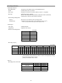
5
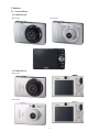
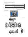
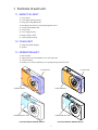
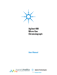
2 Exterior
2-1 Exterior Photos
IXY DIGITAL 90
Black model
Silver model
IXY DIGITAL 10
Black model
Silver model
6
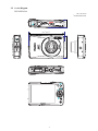
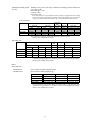
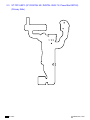
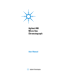
2-2 6-view Diagram
IXY DIGITAL 90
Unit : mm (inch)
Dimensions
19.6* (0.77*)
* Nominal
56.8* (2.24*)
91.6* (3.61*)
7
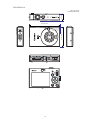
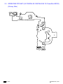
IXY DIGITAL 10
Unit : mm (inch)
Dimensions
19.4* (0.76*)
* Nominal
53.5* (2.11*)
85.9* (3.38*)
8
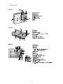
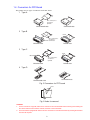
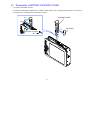
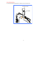
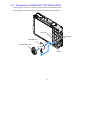
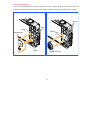
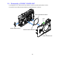
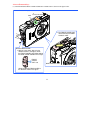
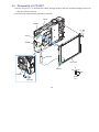
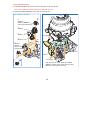
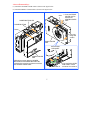
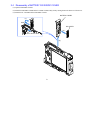
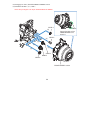
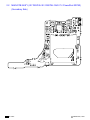
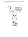
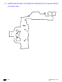
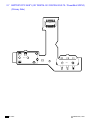
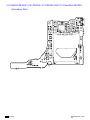
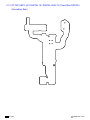
2-3 Nomenclature
IXY DIGITAL 90
9
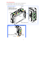
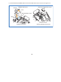
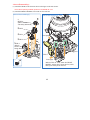
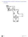
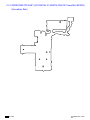
IXY DIGITAL 10
10
3 Specifications
3-1 Product Specifications
Note: Measured data is based on Canon’s standard testing conditions unless otherwise stated.
Imaging Processor
DIGIC III
Image Sensor (CCD)
Camera Effective Pixels
Approx. 7.1 million pixels
Total Pixels
Approx. 7.4 million pixels
Transfer Method
Interline
Image Size
1/2.5-inch type
Aspect Ratio
4:3
Filter Type
Primary color filters (Bayer type)
Lens
Focal Length
5.8 (W) – 17.4 (T) mm (35mm film equivalent: 35 (W) – 105 (T) mm)
f/number (widest aperture)
f/2.8 (W) – f/4.9 (T)
Lens Construction
6 elements in 5 groups (including 2 UA lenses)
Zoom Magnification
3x
Image Stabilizer System
Not available
Focusing Range and Image Area (Image magnification ratios are 35mm film equivalent)
Max. Wide Angle
Shooting Mode
Focusing Range
Focusing Range
Image Area at the Minimum
Focusing Distance
[Image Magnification]
30 cm (12 in.) –
infinity
–
30 cm (12 in.) –
infinity
–
3 – 50 cm
(1.2 in. – 1.6 ft.)
37 x 27 mm
(1.5 x 1.1 in.)
[0.98x]
30 – 50 cm
(12 in. – 1.6 ft.)
108 x 81 mm
(4.3 x 3.2 in.)
[0.32x]
3 m (9.8 ft.) – infinity
–
3 m (9.8 ft.) – infinity
–
3 – 10 cm
(1.2 – 3.9 in.)
9 x 7 mm
(0.35 x 0.28 in.)
[3.8x]
–
–
Not disclosed
–
Not disclosed
–
1 m (3.3 ft.) – infinity
–
1 m (3.3 ft.) – infinity
–
Normal
Auto, Camera M (Manual),
Portrait, Night Snapshot,
Color Accent, Color Swap, Macro
(Special) Scene*1, Movie
Infinity*2
Digital Macro
Fireworks
Kids & Pets
Max. Telephoto
Image Area at the Minimum
Focusing Distance
[Image Magnification]
*1
*2
IXY DIGITAL 10: Scene. Excluding Fireworks and Kids & Pets.
Can not be selected in auto.
Optical Viewfinder
(IXY DIGITAL 10 only)
Type
Real-image zoom viewfinder
Picture Coverage
Not disclosed
Eyepoint
16 mm (0.63 in.)
Dioptric Adjustment
Not available
Electronic Viewfinder
Not available
11
LCD Monitor
Type
Low-temperature polycrystalline silicon TFT color
Effective Pixels
Approx. 230,000 pixels
Display Size
IXY DIGITAL 90: 75.0 mm diagonal (3.0-inch type), with wide viewing angle
IXY DIGITAL 10: 63.3 mm diagonal (2.5-inch type), with wide viewing angle
Picture Coverage
100%
Brightness Adjustment
15 levels
Quick-bright LCD
Available
Variangle
Not available
Focus Control
AF System
TTL autofocus
AF Mode
Single
Manual Focus
Not available
AF Frame
AiAF (Face Detect*1/9-point) / AF (1-point*2)
*1 If no face is detected,
*2 Fixed to center
AF Lock
9 points are used.
Available
• Shooting standby only in movie mode.
AF-assist Beam
Available
Exposure Control
Metering System
Evaluative*1, Center-weighted average, Spot*2
*1 Control to incorporate
*2 Fixed to center
Manual Exposure
Not available
AE Lock
Available
facial brightness in Face Detect AF.
• Shooting standby only in movie mode.
Exposure Compensation
(Still images)
±2 stops in 1/3-stop increments
Exposure Shift (Movies)
±2 stops in 1/3-stop increments
• Shooting standby only.
Program Shift
Not available
Safety Shift
Not available
ISO Speed
Auto*1, High ISO Auto*2, ISO 80/100/200/400/800/1600
*1 Camera automatically sets the optimal speed according to subject brightness.
(Standard Output Sensitivity,
*2 Camera automatically sets the optimal speed according to subject brightness. However,
Recommended Exposure Index)
the ISO speed is set relatively higher than Auto (maximum ISO speed is ISO 800.)
Auto ISO Shift
Available
ND Filter (built-in) Insertion
Not available
White Balance
Modes
Auto, Day Light, Cloudy, Tungsten, Fluorescent, Fluorescent H, Custom
12
Shutter, Aperture
Shutter Type
Mechanical shutter and electronic shutter
Aperture Type
Circular type
Shutter Speeds
15 – 1/1500 sec.
• Shutter speeds vary depending on the shooting modes.
• The following shutter speeds are available in Long Shutter mode:
15, 13, 10, 8, 6, 5, 4, 3.2, 2.5, 2, 1.6, 1.3, 1 (Unit: sec.)
f/number
Widest aperture: f/2.8 (W), f/4.9 (T)
Smallest aperture: f/8.0 (W), f/14 (T)
Flash
<Built-in>
Flash Modes
Auto, on, off
Flash Range
Normal: 50 cm – 3.5 m (W), 50 cm – 2.0 m (T)
(1.6 – 11 ft. (W), 1.6 – 6.6 ft. (T)) (ISO speed: Auto)
Macro: 30 – 50 cm (12 in. – 1.6 ft.) (W/T) (ISO speed: Auto)
Flash Synchro Shutter Speeds 1/500 sec. (Fastest synchronized shutter speed)
Recycling Time (Full Flash)
10 sec. or less (battery voltage: 3.7 V)
Flash Output Compensation
Not available
Manual Flash Output Setting
Not available
FE Lock
Available
Red-eye Reduction
Available
Slow Synchro
Available
Second-curtain Synchro
Not available
Safety FE
Not available
<External>
Not available
<Auxiliary>
Recommended Flash
High-Power Flash HF-DC1
Mounting Method
Mount to the supplied bracket using tripod socket
Trigger System
Detects the flash light from the camera's built-in flash
Shooting Specifications
<Still images, Movies>
Shooting Modes
IXY DIGITAL 90:
Auto, Camera M (Manual), Digital Macro, Color Accent, Color Swap, Stitch assist,
Special Scene*, Movie
* Portrait,
Night Snapshot, Kids & Pets, Indoor, Foliage, Snow, Beach, Fireworks,
Aquarium, Underwater
IXY DIGITAL 10:
Auto, Camera M (Manual)*1, Digital Macro, Portrait, Night Snapshot,
Color Accent, Color Swap, Scene*2, Movie
*1 Stitch assist
*2 Kids & Pets,
Indoor, Foliage, Snow, Beach, Fireworks, Aquarium, Underwater
13
Long Shutter Mode
Available
Digital Zoom
Available
Zoom Magnification
Approx. 4.0x, up to approx. 12x in combination with the optical zoom
• In movie mode, digital zoom is only available for the mode set to Standard, and the optical zoom can be used in shooting standby.
Focal Length
(Optical x Digital)
35 (W) – 420 (T) mm (35mm film equivalent)
Zoom Position
(Optical x Digital)
3.6x, 4.5x, 5.8x, 7.2x, 9.0x, 12x
Safety Zoom
(Stop position:
Optical x Digital)
• Standard only in movie mode.
Large
Medium 1 Medium 2 Medium 3
3.0x
3.6x
4.5x
5.8x
Small
12x
• Maximum magnification without loss of image quality at the each recording pixel.
Digital Tele-converter
My Colors
Approx. 1.5x, approx. 1.9x
Magnification
Focal length (35mm film equivalent)
1.5x
52.5 (W) – 157.5 (T) mm
1.9x
66.5 (W) – 199.5 (T) mm
My Colors Off, Vivid, Neutral, Sepia, Black & White, Positive Film, Lighter Skin Tone,
Darker Skin Tone, Vivid Blue, Vivid Green, Vivid Red, Custom Color*
* Adjustment of contrast, sharpness, saturation, red, green, blue and skin tone are available.
• Saving original image is not available.
Auto Category
People, Scenery, Events
Category Set
Shooting Modes
People
Portrait, Night Snapshot, Kids & Pets
Scenery
Foliage
Events
Indoor, Snow, Beach, Fireworks, Aquarium, Underwater
• When a face or faces have been detected by Face Detect AF, People is always selected
regardless of the shooting mode.
Image Stabilizer
Not available
Camera Start-up Time,
Release Time Lag
IXY DIGITAL 90
Mode
LCD Monitor
Camera Start-up Time*
Release Time Lag
Shooting
On
Approx. 1.0 sec.
0.1 sec. or less
Playback
On
Approx. 1.3 sec.
–
LCD Monitor
Camera Start-up Time*
Release Time Lag
On
Approx. 1.0 sec.
Off
Approx. 0.8 sec.
On
Approx. 1.3 sec.
IXY DIGITAL 10
Mode
Shooting
Playback
* When
Self-timer Shooting
0.1 sec. or less
–
the flash is off.
Approx. 10-sec./approx. 2-sec. delay or custom*
*
Still images only. Shooting start time (0 – 10 sec. (in one-second increments), 15 sec., 20 sec.,
30 sec.) and number of shots (1 – 10 shots (in one-shot increments)) can be specified.
Wireless Controlled Shooting Not available
Remote Shooting
Not available
Disp. Overlay
Off, Gridlines, 3:2 Guide*, Both*
* Still
images only.
14
<Still Images>
Noise Reduction
When shutter speed is set between 15 and 1.3 sec.
Bracketing
Not available
Rec. Review
Off, 2 – 10 sec. (in one-second increments), Hold
• Magnification and image erasing are also available.
Image Inspection Tool
Available
Night Display
Available
Shooting Interval
LCD Monitor
Shooting Interval
On
Approx. 1.4 sec.
Off
–
LCD Monitor
Shooting Interval
On
Approx. 1.4 sec.
Off
Approx. 1.5 sec.
IXY DIGITAL 90
IXY DIGITAL 10
• Large and Fine.
• Focus settings: Normal shooting at max. wide angle.
• The actual shooting interval time consists of the shutter speed added to the above times.
Continuous Shooting
Mode Selection
Not available
Speed
Approx. 1.7 shots/sec. (Large and Fine)
Number of Shots
<Low Level Format>
Unit: shots
Large (L)
Medium 1 (M1) Medium 2 (M2) Medium 3 (M3)
SF
F
N
SF
F
32 MB*2
3
6
22
4
SDC-128M
3
6
40
4
N
N
SF F*1
N
Small (S)
SF
F
N
Widescreen (W)
SF
F
SF
F
10
7
22
18
4
9
13
8
37
29
4
11
N
SDC-512MSH
: Smooth continuous shooting available (See the Recording Capacity for detailed values)
*1 Postcard Date Imprint mode is available.
*2 Memory card included with the camera.
• After exceeding the number of shots shown above, continuous shooting is available when
the shutter button is still pressed. However, the shooting speeds will decrease.
Interval Shooting
Available
<Movies>
Modes
Standard, Fast Frame Rate, Compact, Color Accent, Color Swap, Time Lapse
Audio Specifications
Audio Functions
Sound Memos (also available during rec. review), Sound Recorder
Quantization Bit Rate
16 bit
Sampling Rate
Movies: 44.100 kHz (except Compact) / 11.025 kHz (Compact)
Sound Memos: 11.025 kHz
Sound Recorder: 44.100 kHz / 22.050 kHz / 11.025 kHz
Audio Functions
Microphone, Speaker
Available
Microphone Level
Adjustment
Not available
Wind Filter
Not available
15
Recording Specifications
<Still images, Movies>
Recording Media
SD memory card, SDHC memory card, MultiMediaCard
Format
Normal format, low level format
File Format
Design rule for camera file system, DPOF (Version 1.1) compliant
Data Type
Still images: Exif 2.2 (JPEG)
Movies: AVI (Image data: Motion JPEG; Audio data: WAVE (monaural))
Sound memos, sound recorder: WAVE (monaural)
Folder Settings Management
Capacity
Max. 900, up to 2,000 files can be stored per folder
Customization
Available (Create New Folder (on next shooting), Auto Create*)
* Off,
or user-specified time per day, month, day of the week.
<Still Images>
Color Space
Standard (sRGB)
Compression
Superfine, fine, normal
Number of Recording Pixels
Unit: pixels
Large
3072 x 2304
Medium 1
2592 x 1944
Medium 2
2048 x 1536
Medium 3
1600 x 1200
Small
Postcard Date
640 x 480
Imprint*
Widescreen
* Compression
1600 x 1200
3072 x 1728
is fixed to fine.
Recording Capacity
Unit: images
Large (L)
SF
F
Medium 1 (M1) Medium 2 (M2) Medium 3 (M3)
N
SF
F
N
SF
F
N
SF
F*1
Small (S)
N
SF
F
File Size (KB) 3045 1897 902 2503 1395 695 1602 893 445 1002 558 278 249 150
32 MB*2
SDC-128M
SDC-512MSH
9
40
15
32
11
20
41
64 134
49
87 173
18
32
64
29
52
99
Widescreen (W)
N
SF
F
N
84 2304 1420 678
111 171 270
12
20
42
76 136 269 121 217 411 460 711 1118
53
86 177
156 251 520 190 339 671 295 529 1041 471 839 1590 1777 2747 4317 207 335 686
• The approximate number of images that can be recorded on memory cards of 1 GB and above
can be calculated by using the figures for 512 MB as a reference and extrapolating accordingly.
*1 Postcard Date Imprint mode is available.
*2 Memory card included with the camera.
<Movies>
Recording Pixels, Frame Rate
Recording Pixels
Frame Rate
Standard, Color Accent,
Color Swap
640 x 480
30/15 fps
320 x 240
30/15 fps
Fast Frame Rate
320 x 240
60 fps
Compact
160 x 120
15 fps
Time Lapse
640 x 480
0.5/1 fps*
* Plays
back at 15 fps.
16
Maximum Recording Length
per Clip
Standard, Color Accent, Color Swap: Continuous recording is possible until the file
size reaches 4 GB*
Fast Frame Rate: 1 min.
Compact: 3 min.
Time Lapse: 2 hrs.
* Even
if the file size has not reached 4 GB, the recording is stopped when the recording
time reaches one hour. Depending on memory card capacity and data write speed, recording may stop before the file size reaches 4 GB or the recording time reaches one hour.
<Low Level Format>
Standard, Color Accent, Color Swap
640 x 480
30 fps
320 x 240
15 fps
30 fps
Fast Frame
Rate
Compact
320 x 240
160 x 120
640 x 480
60 fps
15 fps
1 sec. interval 2 sec. interval
1 min.
3 min.
1 min.
3 min.
15 fps
Time Lapse
32 MB*
SDC-128M
29 sec.
SDC-512MSH
: Continuous recording is possible until the memory card becomes full
card included with the camera.
* Memory
Recording Time
Standard, Color Accent, Color Swap
640 x 480
30 fps
Movie Size (KB/sec.)
32
MB*
SDC-128M
SDC-512MSH
Fast Frame
Rate
Compact
320 x 240
160 x 120
60 fps
15 fps
320 x 240
15 fps
1963
1003
14 sec.
27 sec.
30 fps
15 fps
703
Time Lapse
640 x 480
1 sec. interval
373
1363
131
38 sec. 1 min. 7 sec.
20 sec.
3 min. 9 sec.
1 min. 1 sec. 1 min. 56 sec. 2 min. 42 sec. 4 min. 39 sec. 1 min. 27 sec. 13 min. 2 sec.
2 sec. interval
64
32
7 min. 30 sec.
15 min.
31 min. 45 sec. 1 hr. 3 min. 30 sec.
3 min. 57 sec. 7 min. 30 sec. 10 min. 29 sec. 17 min. 58 sec. 5 min. 39 sec. 50 min. 21 sec. 2 hrs. 3 min. 30 sec.
4 hrs. 7 min.
• The approximate recording time available on memory cards of 1 GB and above can be
calculated by using the figures for 512 MB as a reference and extrapolating accordingly.
* Memory card included with the camera.
<Audio>
Recording Time
Sound Memos
Up to 1 minute recording length per image
Sound Recorder
Up to 2 hours recording length per clip
11.025 kHz
Data size (KB/sec.)
32 MB*
SDC-128M
SDC-512MSH
22.050 kHz
44.100 kHz
22
44
88
23 min. 4 sec.
11 min. 32 sec.
5 min. 46 sec.
1 hr. 36 min. 59 sec.
48 min. 30 sec.
24 min. 15 sec.
6 hrs. 14 min. 16 sec.
3 hrs. 7 min. 8 sec.
1 hr. 33 min. 34 sec.
• The approximate recording time available on memory cards of 1 GB and above can be
calculated by using the figures for 512 MB as a reference and extrapolating accordingly.
* Memory card included with the camera.
17
Playback Specifications
<Still images, Movies>
Auto Rotate (Automatic
vertical/horizontal detection)
Available (owing to the Intelligent Orientation Sensor)
Resume Playback
Available
• Images are displayed vertically or horizontally according to the camera's shooting position. For movie playback, the direction depends on the camera's position at the start of
shooting.
• The setting for playback is linked to the setting chosen for shooting.
<Still Images>
Maximum Playback Pixels
4992 x 3328
Playback Modes
Single, index (9 thumbnail images)
Red-eye Correction
Available
Magnification
Approx. 2x – 10x
Rotate
Rotates each image to 90 degrees or 270 degrees
• Advancing and reversing through magnified images available.
• Both the LCD monitor and video output play back the image according to settings.
My Colors
Vivid, Neutral, Sepia, Black & White, Positive Film, Lighter Skin Tone,
Darker Skin Tone, Vivid Blue, Vivid Green, Vivid Red
My Category
People, Scenery, Events, Category 1 – 3, To Do
• Functions that can be carried out by category: image search, erase, protect, slide show,
print.
Jump
Top of the specified Shot Date, My Category, Folder, Movie, By 10 images, By 100 images
• Playback with a selected search key.
• Jumps to the next set of nine images each time button is pressed during index playback.
Histogram
Shooting: Not available
Playback: Available
Overexposure Warning
Not available
Slide Show
Playback interval: 3 – 10 sec., 15 sec., 30 sec.
Repeat: Available
Playlist: All Images, Date, My Category, Folder, Movies, Stills, Custom 1 – 3
Transition Effects
Single image playback: 2 types
Slide show: 3 types
• Only images with DPOF setting can be played back as slide show.
<Movies>
Playback Functions
Normal playback, slow motion*, pause, first frame, last frame, next frame, and
previous frame selectable. Fast forward and fast rewind are available.
• Display playback position and shooting time.
* 5 speed levels including normal-playback speed, without sound.
Editing
Editing Unit
Compatibility
Unwanted portions can be deleted (See Erasing Modes.)
1-sec. increments
See 3-5 Playback Compatibility
Printing Specifications
See 3-4 Direct print
Direct Print
PictBridge, Canon Direct Print, Bubble Jet Direct
DPOF (Version 1.1)
Print Specification
Select images & quantity for printing*, Select by date, Select by category,
Select by folder, Select all images
• Up to a total of 998 images can be specified.
* Up to 99 prints of one image can be specified (other options allow only one print per
image).
18
Erasing Specifications
Erasing Modes
Select image, Select by date, Select by category, Select by folder, Select all images
• The image data in the memory card stored with the design rule for camera file systems
format can be erased. (However, protected images can not be erased.)
• Erasing available in one-second increments using the movie editing function.
Protect (camera)
Select image, Select by date, Select by category, Select by folder, Select all images
• Prevents protected still images (including sound memos) and movies from being deleted
(Specify at playback on camera.)
Protect (SD memory card/
SDHC memory card)
Erasing prohibited for any data recorded on the SD memory card and SDHC memory card
Interface
Computer Interface
USB 2.0 Hi-Speed (mini-B jack)
Communication Settings
MTP, PTP
Audio Output
Monaural (ϕ 3.5 mm jack: Unified type for audio and video output)
Video Output
NTSC or PAL (ϕ 3.5 mm jack: Unified type for audio and video output)
Others
Display Languages
25 languages*
(English, German, French, Dutch, Danish, Finnish, Italian, Norwegian, Swedish,
Spanish, Simplified Chinese, Russian, Portuguese, Greek, Polish, Czech,
Hungarian, Turkish, Traditional Chinese, Korean, Thai, Arabic, Romanian,
Ukrainian, and Japanese)
* Models
for Japanese market available in 2 languages (Japanese and English).
My Camera
Selectable Items
Start-up image, start-up sound, operation sound, self-timer sound, shutter sound
Number of Choices
3 choice (Off is also selectable.)
1: Canon’s original images and sounds (Cannot be customized)
2: Customizable by the user*
3: Customizable by the user*
* The
2nd option features science fiction related images and sounds. The 3rd option features animals related images and sounds. (Default settings)
Registerable Data
Images and sounds recorded with the camera
Images and sounds in the supplied software
Images and sounds downloaded from the online service (Canon Image Gateway*)
* Not
Specifications
available except Japan and Europe.
Item
Start-up image
Lens Retraction Timing
Specifications
320 x 240 pixels, JPEG file with 4:2:0 or 4:2:2, aspect ratio of 4:3, 20 KB or less
Start-up sound
11 kHz: 1.0 sec. or less
8 kHz: 1.3 sec. or less
Operation sound WAVE (monaural)
8 bit
Self-timer sound
11 kHz: 0.3 sec. or less
8 kHz: 0.4 sec. or less
11 kHz: 2.0 sec. or less
8 kHz: 2.0 sec. or less
Shutter sound
11 kHz: 0.3 sec. or less
8 kHz: 0.4 sec. or less
0 sec. (immediately), 1 min. later
Date Function
Date Imprint
Off, Date, Date and time
• Postcard Date Imprint only.
Date Settings
Available up to the year 2037
Date Style
Year/month/day, month/day/year, or day/month/year
19
Clock Display
Display Items
Vertical position: hour/minute/second/year/month/day
Horizontal position: hour/minute/second
• Also available during playback.
Display Colors
12 colors
World Time Display
Available
Direct Transfer
Available (Windows/Macintosh)
All Images, New Images, DPOF Trans. Images*, Select & Transfer, Wallpaper
• Home city (region) and destination city (region) can be selected from 32 choices.
* Images
with check-marks applied by the DPOF function only can be transferred.
Operation Sound
Volume adjustable (5 levels)
Mute
Available (including warning sound*)
* Except
when trying to open the battery cover while the indicator is blinking green.
Shortcut Settings
Disabled (default), Exposure compensation, white balance, Custom White Balance
(load white data), digital tele-converter, Disp. Overlay, Movie, display off,
Play Sound Effect
Reset of All Settings
Available
Power Supplies
Primary Batteries
Not available
Secondary Batteries
Battery Pack NB-4L (Lithium-ion rechargeable battery)
AC Adapter
Compact Power Adapter CA-DC10
• DC Coupler DR-10 is required.
Car Battery Adapter
Not available
Sub-battery
MS lithium secondary battery MS614S
Charging Time
Approx. 4 hours (charged from main battery)
Duration
Approx. 2 weeks (after removal from the fully charged main battery)
Battery Capacity
Number of Images Shot
Playback Time
CIPA Standard compliant
(LCD monitor On)
Canon Standard
(LCD monitor Off)
IXY DIGITAL 90
Approx. 210 shots
–
IXY DIGITAL 10
Approx. 210 shots
Approx. 600 shots
Approx. 4 hours
Power Saving Function
Auto Power Down
(when in idle)
Available
Display Off
10/20/30 sec., 1/2/3 min.
• Shooting mode: Approx. 3 min. later
• Playback mode: Approx. 5 min. later
• Connection to printer: Approx. 5 min. later
• During slide show/connection to computer: The power saving function does not activate
• The Intelligent Orientation Sensor detects the camera being moved and recovers from the
display-off function.
Camera Specifications
Operating Temperatures
0 – 40°C (32 – 104°F)
Operating Humidity
10 – 90%
Dimensions
(excluding protrusions)
IXY DIGITAL 90: 91.6 x 56.8 x 19.6 mm (3.61 x 2.24 x 0.77 in.)
IXY DIGITAL 10: 85.9 x 53.5 x 19.4 mm (3.38 x 2.11 x 0.76 in.)
Weight (camera body only)
IXY DIGITAL 90: Approx. 130 g (4.59 oz.)
IXY DIGITAL 10: Approx. 125 g (4.41 oz.)
20
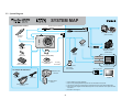
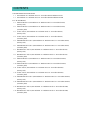
3-2 System Diagram
SYSTEM MAP
Interface Cable IFC-400PCU*1
Supplied with Camera
Direct Interface Cable
Wrist Strap
WS-DC2
Compact Photo Printers*2 *3
(SELPHY Series)
USB Card
Reader
Battery Pack
NB-4L*1
Direct Print Compatible
Bubble Jet Printer*4
(PIXMA series)
Cover for
Battery Pack
PCMCIA
Adapter
Memory Card (32MB)
USB Port
Canon Digital Camera
Solution Disk
Battery Charger
CB-2LV / CB-2LVE*1
PC Card Slot
AV Cable
AVC-DC300*1
SD Memory Card*5
•SDC-128M
•SDC-512MSH
AC Adapter Kit ACK-DC10
Video IN Terminal
Waterproof Case
WP-DC14
Audio IN Terminal
DC Coupler
DR-10
Power Cord
TV/Video
High-Power Flash
HF-DC1
Compact Power Adapter
CA-DC10
*1
*2
*3
*4
*5
21
Also available for purchase separately.
See the user guide supplied with the printer for more information on the printer.
This camera can also be connected to the Card Photo Printer CP-10/CP-100/CP-200/CP-300.
See the user guide supplied with the Bubble Jet printer for more information on the printer and interface cables.
Not sold in some regions.
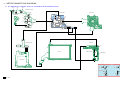
SYSTEM MAP
Interface Cable IFC-400PCU*1
Supplied with Camera
Direct Interface Cable
Wrist Strap
WS-DC2
Compact Photo Printers*2 *3
(SELPHY Series)
USB Card
Reader
Battery Pack
NB-4L*1
Direct Print Compatible
Bubble Jet Printer*4
(PIXMA series)
Cover for
Battery Pack
PCMCIA
Adapter
Memory Card (32MB)
USB Port
Canon Digital Camera
Solution Disk
Battery Charger
CB-2LV / CB-2LVE*1
PC Card Slot
AV Cable
AVC-DC300*1
SD Memory Card*5
•SDC-128M
•SDC-512MSH
AC Adapter Kit ACK-DC10
Video IN Terminal
Waterproof Case
WP-DC13
Audio IN Terminal
DC Coupler
DR-10
Power Cord
TV/Video
High-Power Flash
HF-DC1
Compact Power Adapter
CA-DC10
*1
*2
*3
*4
*5
22
Also available for purchase separately.
See the user guide supplied with the printer for more information on the printer.
This camera can also be connected to the Card Photo Printer CP-10/CP-100/CP-200/CP-300.
See the user guide supplied with the Bubble Jet printer for more information on the printer and interface cables.
Not sold in some regions.
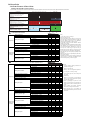
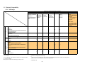
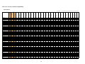
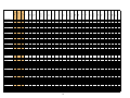
3-3 Shooting/Setting Features List
Camera M
Digital
Long Macro
Shutter
Color
Accent/
Color
Swap
(Special) Scene Mode
Stitch
Assist
Auto
Portrait
Foliage
Snow
Beach Fireworks Aquarium
Under
w ater
Operation
Movies
Indoor
Kids &
Night
Standard
Pets Snapshot
Fast
Frame
Rate
Compact
Time
Lapse
Color
Accent/
Color Swap
Exposure Compensation
{
×
{
×
{
×
{
{
{
{
{
{
{
{
{
{
×
×
×
×
×
FUNC.
Long Shutter Mode
×
{
×
×
×
×
×
×
×
×
×
×
×
×
×
×
×
×
×
×
×
FUNC.
Auto
{
×
{
{
{
{
{
{
{
{
{
{
{
{
{
{
{
{
{
{
{
ISO.
High ISO Auto
{
×
{
×
×
{
×
×
×
×
×
×
×
×
×
×
×
×
×
×
×
×
ISO Speed
White Balance
Drive Mode
80/100/200/400/800/1600
{
{
{
×
×
×
×
×
×
×
×
×
×
×
×
×
×
×
×
×
Auto
{
{
{
{
{
{
{
{
{
{
{
{
{
{
{
{
{
{
{
{
{
Other than Auto
{
{
{
×
{*1
×
×
×
×
×
×
×
×
×
×
×
{
{
{
{
×
Single Shooting
{
{
{
{
{
{
{
{
{
{
{
{
{
{
{
{
{
{
{
{
{
Continuous Shooting/Continuous Shooting AF
{
{
{
×
×
×
{
{
{
{
{
{
{
{
{
{
×
×
×
×
×
Self-timer 2 sec./10 sec.
{
{
{
{
{
{
{
{
{
{
{
{
{
{
{
{
{
{
{
{
{
Custom Self-timer
{
{
{
×
×
{
{
{
{
{
{
{
{
{
{
{
×
×
×
×
×
{
{
{
×
{
×
×
×
×
×
×
×
×
×
×
×
{
{
{
{
×
FUNC.
Evaluative
{
{
{
{
{
{
{
{
{
{
{
{
{
{
{
{
{
{
{
{
{
FUNC.
Center-weighted Average
{
×
{
×
×
×
×
×
×
×
×
×
×
×
×
×
×
×
×
×
×
My Colors
Metering System
FUNC.
DRIVE.
Spot
{
×
{
×
×
×
×
×
×
×
×
×
×
×
×
×
×
×
×
×
×
Number of recording pixels selection (still images)
{
{
{*2
{
{*2
{
{
{
{
{
{
{
{
{
{
{
×
×
×
×
×
FUNC.
Compression selection (still images)
{
{
{
{
{
{
{
{
{
{
{
{
{
{
{
{
×
×
×
×
×
FUNC.
640 × 480, 30 fps/15 fps
×
×
×
×
×
×
×
×
×
×
×
×
×
×
×
×
{
×
×
{
{
(Large)
320 × 240, 30 fps/15 fps
×
×
×
×
×
×
×
×
×
×
×
×
×
×
×
×
{
×
×
×
{
FUNC.
320 × 240, 60 fps
×
×
×
×
×
×
×
×
×
×
×
×
×
×
×
×
×
{
×
×
×
160 × 120, 15 fps
Number of
Recording Pixels/
Frame Rate
Selection (movies)
×
×
×
×
×
×
×
×
×
×
×
×
×
×
×
×
×
×
{
×
×
(Light)
AE/FE Lock
{
×
{
×
×
×
×
×
×
×
×
×
×
×
×
×
×
×
×
×
×
S1+ ISO
Exposure Shift
×
×
×
×
×
×
×
×
×
×
×
×
×
×
×
×
{
{
{
{
×
ISO
AF Lock
{
{
{
×
×
×
×
×
×
×
×
×
×
×
×
×
{
{
{
{
×
S1 + AF
Normal
{
{
×
{
{
{
{
{
{
{
{
{
{
{
{
{
{
{
{
{
{
AF
Macro
{
{
{
{
{
{
{
{
{
{
×
{
{
{
×
{
{
{
{
{
{
Focusing zone
Flash
Finder Setting
Infinity
{
{
×
{
{
×
{
{
{
{
×
{
{
{
×
{
{
{
{
{
{
Auto
{
×
×
{
×
{
{
{
{
{
×
×
{
{
{
{
×
×
×
×
×
On
{
{
×
{
{
×
{
{
{
{
×
{
{
{
{
{
×
×
×
×
×
Off
{
{
{
{
{
{
{
{
{
{
{
{
{
{
{
{
×
×
×
×
×
LCD Monitor (off)
{
{
×
×
×
{
{
{
{
{
{
{
{
{
{
{
×
×
×
×
×
LCD Monitor (no infomation)
{
{
{
×
×
{
{
{
{
{
{
{
{
{
{
{
{
{
{
{
×
LCD Monitor (infomation view) {
FLASH
DISP.
{
{
{
{
{
{
{
{
{
{
{
{
{
{
{
{
{
{
{
{
Stitch Direction Selection (Right, Left)
×
×
×
×
{
×
×
×
×
×
×
×
×
×
×
×
×
×
×
×
×
FUNC. (IXY D90)
MENU (IXY D10)
AiAF
Off
{
{
{
{
{
{
{
{
{
{
{
{
{
{
{
{
×
×
×
×
×
MENU
On (9-point)
{
{
{
{
×
{
{
{
{
{
×
{
{
{
{
{
{
{
{
{
{
Face Detect
{
{
{
{
×
{
{
{
{
{
×
{
{
{
{
{
×
×
×
×
×
{
{
{*3
×
×
{
{
{
{
{
{
{
{
{
{
{
{
×
×
×
×
{
{
×
×
×
{
{
{
{
{
{
{
{
{
{
{
×
×
×
×
×
On
{
×
×
×
{
×
×
×
×
×
×
×
×
×
×
{
×
×
×
×
×
MENU
Off
{
{
×
{
{
{
{
{
{
{
×
{
{
{
{
×
×
×
×
×
×
MENU
Custom Self-timer Setting (Time/Shots)
{
{
{
×
×
{
{
{
{
{
{
{
{
{
{
{
×
×
×
×
×
MENU
Auto ISO Shift
On
{
×
{
×
×
{
×
×
×
×
×
×
×
×
×
×
×
×
×
×
×
MENU
Off
{
{
{
{
{
{
{
{
{
{
{
{
{
{
{
{
×
×
×
×
×
AF-assist Beam
{
{
{
{
{
{
{
{
{
{
×
{*4
{
{
{
{
{
{
{
{
{
MENU
Review (Rec. review)
{
{
{
{
{
{
{
{
{
{
{
{
{
{
{
{
×
×
×
×
×
MENU
Save Original
×
×
×
{
×
×
×
×
×
×
×
×
×
×
×
×
×
×
×
×
×
MENU
Off
{
{
{
{
{
{
{
{
{
{
{
{
{
{
{
{
{
{
{
{
{
MENU
Gridlines
{
{
{
{
×
{
{
{
{
{
{
{
{
{
{
{
{
{
{
{
{
3:2 Guide/Both
Digital Zoom
Digital Tele-converter
Slow Synchro
Disp. Overlay
MENU
{
{
{
{
×
{
{
{
{
{
{
{
{
{
{
{
×
×
×
×
×
Date stamp (Postcard only)
{
{
×
{
×
{
{
{
{
{
{
{
{
{
{
{
×
×
×
×
×
MENU
Formatting (Check mark for low level format)
{
{
{
{
×
{
{
{
{
{
{
{
{
{
{
{
{
{
{
{
{
MENU
[How to read symbols in the table]
{ : Selectable or optimum value is automatically set by the camera.
Settings can be made for the first image only with Stitch Assist, unless noted otherwise.
X : Not selectable.
Colored cells ( ) : The settings will be retained even when power is turned off.
*1 : Custom White Balance is not available.
*2 : Postcard and Widescreen are not available.
*3 : Always set to on.
*4 : Available only when the flash is set to on.
23
3-4 Direct Print
3-4-1Print Features of Direct Print
• Printing with SELPHY CP Series Printers
The product name of the camera and the printer that has been described in the table is Japanese names. However, the product not sold in Japan has described an overseas name.
CP730 / 720 / 710 / 510 / 500 / 400 / 330 / 220
CP-300 / 200 / 100 / 10
Product Name
CP600, ES1
PowerShot G3 / G2
PowerShot S45 / S40 / S30
PowerShot A40 / A30 / A20 / A10 / A200 / A100
IXY DIGITAL 320 / 300a / 200a / 300 / 200
PowerShot Pro1
PowerShot G5
PowerShot S1 IS / S50
PowerShot A80 / A70 / A60 / A300
IXY DIGITAL 400 / L / 30
PowerShot G6
PowerShot S70 / S60
PowerShot A95 / A85 / A75 / A520 / A510 / A400 / A310
IXY DIGITAL 500 /450 / L2 / 50 / 40 / 30a
IXY DIGITAL 700 / 600 / 60 / 55 / L3 / WIRELESS
PowerShot A620 / A610 / A410
PowerShot S3 IS / S2 IS / S80
PowerShot A700 / A540 / A530 / A430 / A420
IXY DIGITAL 800 IS / 80 / 70
PowerShot TX1
PowerShot G7
PowerShot A710 IS / A570 IS / A560 / A550 / A640 / A630 / A460 / A450
IXY DIGITAL 1000 / 900 IS / L4 / 90 / 10
(
: When Connecting with PictBridge)
(
: When Connecting with PictBridge)
Canon Direct Print features
Single Image Print
Setting the Number of Copies*1
Standard*2
Multiple*3
Easy Print
Setting the Print Style
ID Photo Print
Borderless / Bordered
Date
Selecting the Print Type
Date and File Number Print
Setting the Print Style
PictBridge features
Setting the Print Effect
Copies*4
O
O
O
O
×
O
O
O
O
O
[NOTE]
*1
*2
*3
1 to 99 copies can be set per image.
Prints one image per page.
Prints eight copies of the same image on one page. This
option can only be selected when printing on credit card
size paper. When the print style is set to [Multiple],
images are printed without any date or border.
In PowerShot A20/A10 and IXY DIGITAL 300/200,
trimming is not possible.
In PowerShot A60/A40/A30/A200/A100 and IXY DIGITAL 300a/200a, you can select the print area from the
top-/center-/buttom-aligned. Depending on a paper size
and aspect ratio of the image, the print area may be
aligned to the left or right. However, the print area can be
set, when the print style is [Borderless] and [Multiple].
When the print type is set to [Index], the [Date] cannot
be printed.
When the print type is set to [Standard], the [File Number] cannot be printed.
Communication setting with the printers (CP730/720/
710/510) needs to be changed to PictBridge for fullsized borderless printing on wide-size paper.
×
×
Standard
Index
Both (Standard + Index)
Date*5
File Number*6
Standard*2
Multiple*3
Borderless / Bordered
O
O
O
O
O
O
O
O
O
O
O
O
O
O
O
O
O
O
O
O
O
O
4
5
6
7
O
O
O
O
O
O
O
O
O
O
O
O
O
O
O
×
×
×
×
×
×
×
×
×
×
×
×
×
×
O
O
O
O
O
O
O
O
O
O
O
O
O
O
O
O
O
O
O
O
O
O
O
O
O
O
O
O
O
×
×
×
×
×
×
×
×
×
O
O
O
O
O
O
O
O
O
O
O
O
O
O
O
O
O
O
O
O
O
O
O
O
O
O
O
O
O
O
×
×
×
×
×
×
×
×
×
×
×
×
×
×
O
O
O
O
O
O
O
O
O
O
O
O
O
O
O
O
O
O
O
O
O
O
×
×
×
×
×
×
×
×
×
×
×
×
Date
File Number
Auto*1 (On/Off)
VIVID / NR / VIVID+NR
Face brightness adjustment
Red-eye1 correction*2
Red-eye2 correction*3
×
Setting the Number of
Setting the Print Area (Trimming)
Selecting the Paper Size*5
Selecting the Paper Type*6
Setting the Layout
Movie Print
Borderless / Bordered
N-up*7
Fixed Sixe*8
ID Photo Print
20 image index with shooting information
Contact-sheet type 35 image index
Print with the shooting information
Sequence-frame
Single-frame*9
Several Selected Images Print
All Image Print
Selecting the Print Type
Date and File Number Print
Setting the Print Effect
Setting the Number of Copies*4
Selecting the Paper Size*5
Selecting the Paper Type*6
Setting the Layout
O
O
O
O
×
*4
*5
*6
*7
: Canon proprietary feature
Date and File Number Print
Printing with
DPOF Print
Settings
O
O
O
O
Sequence-frame
Single-frame
Single Image Print
Easy Print
3
O
O
O
O
O
O
O
O
O
O
O
O
O
O
O
O
O*7
Several Selected Images Print
All Image Print
Setting the Number of Copies*1
Printing with
DPOF Print
Settings
2
O
O
O*4
Setting the Print Area (Trimming)
Movie Print
1
×
×
×
×
×
×
×
×
O
O
O
O
O
O
Standard
Index
Both (Standard + Index)
Date*10
File Number*10
Auto*1 (On/Off)
VIVID / NR / VIVID+NR
Face brightness adjustment
Red-eye1 correction*2
Red-eye2 correction*3
×
Borderless / Bordered
N-up*7
Fixed Sixe*8
ID Photo Print
20 image index with shooting information
Contact-sheet type 35 image index
Print with the shooting information
24
×
×
×
×
×
×
×
O
×
O
×
[NOTE]
*1
Uses the camera's shooting information to
optimize the image data.
*2
Red-eye correction only.
*3
Red-eye + NR + Face brightness adjustment.
*4
1 to 99 copies can be set per image.
*5
For the usable paper size, refer to the printer
user guide.
*6
Default only.
*7
Prints 2, 4 or (8) images on a single sheet of
paper. (8 can only be selected when printing
on credit card size paper.)
*8
Prints by specifying the print size of the
image on a sheet of paper. For the paper size
and the print size, refer to the direct print user
guide.
*9
Only available with cameras supporting
Movie Print (in single frames) function.
*10 When
the print type is set to [Index], the
[Date] and [File Number] cannot be set at the
same time.
• Printing with Canon Bubble Jet Printers (PIXMA series/SELPHY DS series)
The product name of the camera and the printer that has been described in the table is Japanese names. However, the product not sold in Japan has described an overseas name.
Product Name
PIXUS 470PD /
450i / 50i
BJ 895PD /
535PD /
F890PD
PIXUS MP390 / PIXUS 865R /
860i / 560i
MP375R /
MP370
PIXUS 475PD /
455i / 80i
PIXUS MP900
PIXUS iP9910 /
9900i / 990i /
960i / 900PD
SELPHY DS700
PIXUS MP790 / PIXUS iP4200
MP770
PIXMA MP750
PIXUS iP8600 /
iP8100 / iP7100 /
iP6100D / iP4100 /
iP4100R / iP3100 /
iP2000 / iP90
PIXMA iP5000
PIXUS MP500 /
MP170
PIXMA MP530 /
MP450 / MP150
PIXMA iP6220D /
iP6210D
PIXUS mini220
SELPHY DS810
PIXUS MP950 / PIXUS iP6700D /
MP830 / MP800 / iP6320D /
iP6310D
MP800R
PIXUS iP7500 /
iP6600D / iP5200 /
iP5200R
PIXUS ix5000 /
PIXMA ix4000
PIXUS iP4300 /
iP3300
PowerShot G3 / G2
PowerShot S45 / S40 / S30
IXY DIGITAL 320 / 300a / 200a
PowerShot Pro1
PowerShot G6 / G5
PowerShot S1 IS / S70 / S60 / S50
PowerShot A95 / A85 / A80 / A75 /
A70 / A60 / A400 / A310 / A300
IXY DIGITAL 500 / 450 / 400 /
L / 30a / 30
PowerShot A520 / A510
IXY DIGITAL L2 / 50 / 40
PowerShot S2 IS
IXY DIGITAL 600 / 55
PowerShot S3 IS / S80
PowerShot A700 / A620 / A610 /
A540 / A530 / A430 / A420 / A410
IXY DIGITAL 800 IS / 700 / L3 /
80 / 70 / 60 / WIRELESS
PowerShot TX1
PowerShot G7
PowerShot A710 IS / A570 IS /
A560 / A550 / A640 / A630 /
A460 / A450
IXY DIGITAL 1000 / 900 IS / L4 /
90 / 10
1
Single Image Print
Setting the Number of Copies*1
O
O
O
O
O
O*3
O
O
O
O
O
O
O
Paper Size*2
Borderless / Bordered
Date
Setting the Print Style
Setting the Print Area (Trimming)
Several Selected Images Print
All Image Print
Setting the Number of Copies*1
Printing
with DPOF
Print
Settings
Standard
Index
Both (Standard + Index)
Date
File Number
Borderless / Bordered
Selecting the Print Type
Date and File Number Print
Setting the Print Style
PictBridge features
: Canon proprietary feature
Single Image Print
Date and File Number
Print
Setting the Print Effect
Easy Print
Printing
with DPOF
Print
Settings
PIXUS MP960 /
MP810 / MP600 /
PIXMA MP600R
PIXMA iP5300
PIXUS mini260
Buble Jet Direct is not available
Bubble Jet Direct features
Easy Print
PIXUS MP510 / PIXUS Pro9500 /
MP460
Pro9000
PIXMA MP180 /
MP160
Date
File Number
Auto*1 (On/Off)
VIVID / NR / VIVID+NR
Face brightness adjustment
Red-eye1 correction*3
Red-eye2 correction*4
Setting the Number of Copies*5
Setting the Print Area (Trimming)
Selecting the Paper Size*6
Selecting the Paper Type*7
Borderless / Bordered
N-up*8
Fixed Sixe*10
Setting the Layout
ID Photo Print
20 image index with shooting information*11
Contact-sheet type 35 image index*12
Print with the shooting information*13
Sequence-frame
Movie Print
Single-frame*14
Several Selected Images Print
All Image Print
Standard
Selecting the Print Type
Index
Both (Standard + Index)
Date*15
Date and File Number
Print
File Number*15 16
Auto*1 (On/Off)
VIVID / NR / VIVID+NR
Setting the Print Effect
Face brightness adjustment
Red-eye1 correction*3
Red-eye2 correction*4
Setting the Number of Copies*5
Selecting the Paper Size*6
Selecting the Paper Type*7
Borderless / Bordered
N-up*8
Fixed Sixe*10
Setting the Layout
ID Photo Print
20 image index with shooting information*11
Contact-sheet type 35 image index*12
Print with the shooting information*13
[NOTE]
*1
1 to 99 copies can be set per image.
*2
For the usable paper size, refer to the printer user guide.
*3
In PowerShot A60 and IXY DIGITAL 300a/200a, you can select the print area
from Top/Center/Bottom. Depending on a paper size and aspect ratio of the image,
the print area may be aligned to the left or right. However, the print area can be set
when the print style is [Borderless].
×
O
2
3
4
5
6
7
8
9
O
O
O
O
O
O
O
O
×
×
×
×
O
O
×
×
×
×
U*2
O
O
O
O
O
O
O
O
O
×
×
×
×
×
×
×
×
×
×
×
×
O
O
O
O
O
O
O
O
O
O
O
O
O
O
O
O
O
O
O
O
O
O
O
O
O
O
O
O
O
O
O
O
O
O
O
O
O
O
O
O
O
O
O
×
×
×
×
×
×
×
×
×
×
×
×
×
×
×
×
×
×
×
×
×
O*9
×
×
×
×
×
×
O
O
O
O
O
O
O
O
O
O
O
O
O
O
O
O
O
O
O
O
O
O
O
O
O
O
O
O
×
×
×
×
O
O
O
O
O
O
O
O
O
O
O
O*9
O
O
O
O
O
O
O*9
O*9
×
×
×
×
×
×
×
×
×
×
×
×
×
×
×
×
×
×
O
O
O
O
O
O
O
O
O
×
×
×
O
O
O
O
O
O
O
O
O
O
O
O
O
O
O
O
O
O
O
O
O
O
O
O
O
O
O
O
O
O
O
O
O
×
×
×
×
O
O
O
O
O
O
O
O
O
O*9
O*9
O
O
O
O
O
O
O
O
O
O
O
O
O
O
O
O
O
O
×
×
×
×
×
×
O
O
O
O
O
O
O
O
O
×
×
×
×
O
O
×
×
×
×
U*2
O
O
O
O
O
O
O
O
O
O
O
O
O
O
×
×
×
×
×
×
×
×
×
×
×
×
O
O
O
O
O
O
O
O
O
O
O
O
O
O
O
O
O
O
O
O
×
×
×
×
×
×
×
×
×
×
×
×
×
×
×
×
×
×
O*9
O*9
O
O
O
O
O
×
×
×
×
×
×
×
×
×
×
×
×
×
×
×
25
×
O
O
O
O
O
O
O
O
O
O
O
O
O
O
×
[NOTE]
*1
*2
*3
*4
Uses the camera's shooting information to optimize the image data.
VIVID only.
Red-eye correction only.
Red-eye + NR + Face brightness
adjustment.
*5 1 to 99 copies can be set per image.
*6 For the usable paper size, refer to
the printer user guide.
*7 For the usable paper type, refer to
the printer user guide.
*8 Prints 2, 4, 9 or 16 images on a single sheet of paper. The number of
images that can be arranged on a
single sheet of paper is different
depending on the printer and the
paper size. Then, refer to the print
user guide.
*9 Not available when connecting with
the PIXUS Pro9500 printer.
*10 Prints by specifying the print size of
the image on a sheet of paper. For
the paper size and the print size,
refer to the direct print user guide.
*11 Only available with cameras supporting 20 image index layout with
shooting information.
*12 Only available with cameras supporting contact-sheet type 35 image
index layout.
*13 Not available when printing without
borders.
*14 [Single-frame] is only possible,
when the camera corresponds to the
Movie print (Single-frame).
*15 When the print type is set to
[Index], the [Date] and [File Number] cannot be set at the same time.
*16 When the print type is set to [Standard], the [File Number] cannot be
printed.
3-4-2 The Connection between Digital Cameras and Printers
The connection between Canon digital cameras (PowerShot series and IXY series) and printers shows in Table 1.
Canon Direct Print / Bubble Jet Direct /
PictBridge support
Digital Cameras
Printers
CP series (Canon
Direct Print support)
CP-10
CP-100
CP series
(Canon Direct Print,
PictBridge support)
CP-200/300
CP220/330
SELPHY CP series
(Canon Direct Print,
PictBridge support)
CP730/720/
710/510
CP500/400
ES1, CP600
Canon Direct Print /
Bubble Jet Direct support
Cameras released in 2003
Cameras released in 2004
and 2005
Cameras released in 2006
(Except for PS Pro1/S1 IS)
and 2007
(Except for PS A520/A510)
PS A520/A510
PS Pro1/S1 IS
PS G3/G2/S45/S40/S30,
ID 320/300a/200a
PS A40/A30/A20/A10/
A200/A100,
ID 300/200
Canon Direct Print
Canon Direct Print /
PictBridge*
PictBridge
PIXMA series
(Bubble Jet Direct support)
-
PIXMA series
(Bubble Jet Direct, PictBridge support)
SELPHY DS series
(Bubble Jet Direct, PictBridge support)
Canon Direct Print
support
Bubble Jet Direct
PictBridge
-
Other manufacturer’s Printer
(PictBridge support)
-
-
• IXY (ID) is the name for Japanese market.
• The supporting digital cameras and printers are included by improvement of the version of the firmware.
• For SLR digital cameras and video cameras, refer to their Technical Guidance.
* It is possible to change printer connection to PictBridge with the camera. However, the change is unnecessary, except when full-sized borderless printing on wide-size paper with
CP730/720/710/510.
Table 1 The conuection between Digital Cameras and Printers
26
3-5 Playback Compatibility
3-5-1 Still Images
Cameras for playback (except SLR cameras)
CF card
SD memory card
ID 400/320/300a/300/ PS G3/G2/G1 PS Pro1
ID 500/450
ID 30
ID 600/55/50/40/
200a/200, IXY DIGITAL PS Pro90 IS PS G6/G5
30a/L2/L
PS S1 IS
PS S20/S10
PS A70/A60/A40/A30/
A20/A10/A300/A200/
A100
PS S50/S45/
S40/S30
PS S70/S60
PS S2 IS
PS A95/A85/
A80/A75/A310
PS A400
SD•MMC*
ID 90/10
PS TX1
PS A570 IS/A560/A550/
A460/A450
ID 1000/900 IS/800 IS/
700/80/70/60/L4/L3/
WIRELESS
PS G7
PS S3 IS/S80
PS A710 IS/A700/A640/
A630/A620/A610/A540/
A530/A520/A510/A430/
A420/A410
ID 500/450/400/320/300a/300/200a/200, IXY DIGITAL
PS S1 IS
O
O
O
O
PS Pro90 IS
O*1
O
O
O*1
*1
*1
*1
PS S70/S60/S50/S45/S40/S30
PS Pro1
ID 600/55/50/40/30a/30/L2/L
O*1*2
O*2
O
O*1
*1*2
*1
*1
PS S2 IS
O
O
O
O*3
O*3
O
*2
*2
O*2*3
O*3
O
Cameras for shooting (except SLR cameras)
PS S20/S10
CF
SD
PS A95/A85/A80/A75/A70/A60/A40/A30/A20/A10/
A310/A300/A200/A100
PS G6/G5/G3/G2/G1
PS A400
ID 90/10
PS TX1
PS A570 IS/A560/A550/A460/A450
ID 900 IS/800 IS/700/80/70/60/L4/L3/WIRELESS
PS S3 IS
SD
PS A710 IS/A700/A620/A610/A540/A530/A520/
MMC* A510/A430/A420/A410
ID 1000
PS G7
PS S80
PS A640/A630
PS : PowerShot
ID : IXY DIGITAL (The model names of IXY are for Japanese market)
O : Playback available
: Playback available when interchange of memory cards
*1 Thumbnail is displayed for RAW image
*2 JPEG file can be played-back up to 3200 x 2400 pixels (Thumbnail
*3 Images recorded in the MultiMediaCard may not be played-back.
*
MultiMediaCard
27
displays when more than 3200 x 2400 pixels)
Cameras for shooting
3-5-2 Movies
PS G2/G1
PS Pro90 IS
PS S40/S30
ID 300a/300/200a/200
PS A40/A30/A200/A100
ID 500/450/400/320
CF
PS Pro1
PS G6/G5/G3
PS S70/S60/S50/S45
PS A95/A85/A80/A75/A70/A60/A310/A300
PS S1 IS
ID 30a/30/L2/L
PS 400
SD
ID 600/55/50/40
PS S2 IS
PS A520/A510
PS A550/A460/A450
ID 800 IS/700/80/70/60/L3/WIRELESS
PS S3 IS (except 320 x 240, 60 fps)/
S80 (except XGA)
PS A710 IS/A700/A640/A630/A620/A610/
A540/A530/A430/A420/A410
SD
PS S3 IS (320 x 240, 60 fps)
MMC* PS S80 (XGA)
PS TX1*3 *4, PS A570 IS*3, PS A560,
ID 90/10*3
ID 1000/900 IS/L4
PS G7
Time Lapse: PS TX1, PS A570 IS,
ID 90/10
1280 x 720: PS TX1
Cameras for playback
CFcard
SD memory card
PS
ID 30a/30/ ID 600/55/ PS
IXY DIGITAL PS G2/G1
ID 300a/300/ PS Pro1
S1 IS L2/L
50/40
A520/
PS S20/S10 PS Pro90 IS 200a/200
PS G6/G5/G3
A510
PS
A40/A30/
PS
S2
IS
PS
400
PS A20/A10 PS S40/S30
PS S70/S60/S50/S45
A200/A100
ID 500/450/400/320
PS A95/A85/A80/A75/
A70/ A60/A310/A300
SD•MMC*
ID 800 IS/700/80/ PS
70/60/L3/
A550/A460/
WIRELESS
A450
PS S80
PS S3 IS
PS A700/A620/
PS A710 IS/
A610/A540/A530/ A640/A630
A430/A420/A410
×
O
O*1
O
O
×
O*1
O
O
O
×
O*1
O*1
O
O
×
×
×
×
O
×
×
*1
*1
×
×
×
×
×
×
×
×
×
*1
*1
×
×
×
×
ID 1000/
900 IS/
L4
PS G7
ID
90/10
PS
TX1
PS
A570 IS/
A560
×
O
O
O
O
O
O
O
×
×
O
×
×
×
×
O*2
O*2
O
O
O
O
O
O
O
O
O
O
O
O
O
×
×
×
O*2
×
O
O
O
O
×
×
×
×
×
×
×
×
×
×
×
×
×
×
×
O
O
O
O
O
O
O
×
×
×
×
×
×
×
×
×
×
O
O
×
×
×
×
×
×
×
×
×
×
×
O
PS : PowerShot
ID : IXY DIGITAL (The model names of IXY are for Japanese market)
O : Playback available
: Playback available when interchanging of memory cards
× : Playback not available
*1 Playback not available when file size or recording time exceeds each limit.
*2 Images recorded in the MultiMediaCard (MMC) may not be played-back.
*3 Except Time Lapse Movie
*4 Except 1280 x 720
*
MultiMediaCard
28
3-6 List of Accessory and Its Compatibility
3-6-1Camera
PS: PowerShot
<Battery>
NB-5H
NB-1L/1LH
NB-2L/2LH
NB-3L
NB-4L
NB-5L
BP-511/511A
BP-512/514
NB4-100/NB4-200
NB4-300
<Adapter/Charger>
100E(DK110)
ACK300
ACK500
ACK600
ACK900
ACK700
ACK800
ACK-DC10
ACK-DC20
ACK-DC30
CA-DC20
CA-PS700 (N)
CA-560
CA-570 + CG-560/570
CR-560
CB-5L/CG-580
CB-2L/2LE
CB-2LS/2LSE
CB-2LT/CB-2LTE
CB-2LU/2LUE
CB-2LV/2LVE
CB-2LW/2LWE
CB-2LX/CB-2LXE
CB-3AH(CBK-100)
CB-4AH(CBK4-200)
CBC-NB1
CBC-NB2
CB-5AH(CBK4-300)
<DC Coupler>
DR-100/100A
DR-300
DR-500
DR-700
DR-900
DR-10
DR-20
DR-30
PS
PS
PS
TX1
A570 IS
A560
A550
A540
A530
A520
A510
A460
A450
A420
A410
A400
A310
ID
90/10
WIRELESS/
G7
80/70
60/55/
50/40
PS
ID
PS
ID
1000
900 IS
800 IS
A710 IS L4
A700
L3
ID: IXY DIGITAL (The model names of IXY are for Japanese market)
PS
PS
PS
ID
ID
PS
PS
PS
PS
PS
ID
PS
PS
PS
PS
ID
ID
PS
PS
ID
PS
PS
A640
A630
A620
A610
S80
S3 IS
S2 IS
700
600
30a
30
L2
L
G6
A95
A80
S70
S60
A85
A75
A70
A60
A300
A200
A100
500
450
400
S1 IS
Pro1
PS G5
PS G3
S50
S45
S40
S30
320
200a
200
300a
300
A40
A30
A20
A10
G2
IXY
DIGITAL
Pro
90 IS
G1
O
O
O
O
O
-
O
-
O
-
O
O
O
-
O
O
O
-
O
O
O
-
O
-
O
O
-
O
O
O
-
O
O
O
O
O
-
O
O
O
O
-
O
O
-
O
-
O
-
O
-
O
O
O
O
-
O
-
O
-
O
-
O
O
O
O
O
O
O
O
O
O
-
O
O
O
O
-
O
O
-
O
O
O
O
O
O
-
O
O
O
O
O
O
O
-
O
O
O
O
O
O
-
O
-
O
O
O
O
-
O
O
O
O
O
O
O
-
O
O
O
O
O
O
O
O
O
O
O
-
O
O
O
O
O
O
O
O
-
O
O
O
O
-
O
O
O
-
O
O
O
-
O
O
O
-
O
O
O
O
O
O
O
O
-
O
O
O
O
-
O
O
O
O
-
O
O
O
O
-
-
-
O
-
O
-
O
-
-
-
O
-
-
O
-
-
-
-
O
-
-
-
O
-
-
-
-
O
-
O
-
O
-
-
-
O
-
-
-
29
PS
PS
PS
TX1
A570 IS
A560
A550
A540
A530
A520
A510
A460
A450
A420
A410
A400
A310
ID
90/10
WIRELESS/
G7
80/70
60/55/
50/40
PS
ID
PS
ID
1000
900 IS
800 IS
A710 IS L4
A700
L3
PS
PS
PS
ID
ID
PS
PS
PS
PS
PS
ID
PS
PS
PS
PS
ID
ID
PS
PS
ID
PS
PS
A640
A630
A620
A610
S80
S3 IS
S2 IS
700
600
30a
30
L2
L
G6
A95
A80
S70
S60
A85
A75
A70
A60
A300
A200
A100
500
450
400
S1 IS
Pro1
PS G5
PS G3
S50
S45
S40
S30
320
200a
200
300a
300
A40
A30
A20
A10
G2
IXY
DIGITAL
Pro
90 IS
G1
<Lens Accessory>
WC-DC52
WC-DC58
WC-DC58N
WC-DC52A
WC-DC58A
WC-DC58B
WC-DC10
TC-DC52
TC-DC52A
TC-DC52B
TC-DC58
TC-DC58N
TC-DC58A
TC-DC58B
TC-DC58C
TC-DC10
250D 52mm
250D 58mm
500D 52mm
500D 58mm
LA-DC52
LA-DC52B
LA-DC52C
LA-DC52D
LA-DC52E
LA-DC52F
LA-DC52G
LA-DC58
LA-DC58B
LA-DC58C
LA-DC58D
LA-DC58E
LA-DC58F
LA-DC58G
LA-DC58H
LA-DC10
LA-DC20
FA-DC58A
LH-DC58
LH-DC10
LH-DC20
LH-DC30
LH-DC40
LAH-DC20
LAH-DC10
<Speedlite>
220EX
380EX
420EX
430EX
550EX
580EX
(MR-14EX)
O (except
560/550/530)
O (except
560/550/530)
O (except
560/550/530)
O (except
570/560/550/
530)
O (570)
-
-
-
-
-
-
-
-
-
-
-
-
-
O
-
O
-
-
-
-
-
-
-
-
O
-
-
-
-
-
-
O
-
-
O
-
-
O
-
O
-
O
-
-
-
O
-
-
-
O
-
-
O
-
-
O
-
-
-
-
O
O
-
-
O
-
O
-
-
-
-
-
-
-
-
-
-
-
-
-
O
-
O
-
-
-
-
-
-
-
-
O
-
-
-
-
-
-
O
-
-
O
-
-
O
-
O
O
-
-
-
O
-
-
O
-
-
-
O
-
O
-
O
-
-
-
-
-
O
-
-
-
O
-
-
-
-
-
-
-
-
-
-
-
-
-
O
-
O
-
-
-
-
-
-
-
-
O
-
-
-
-
-
-
-
-
O
-
-
-
-
O
-
-
-
O
-
O
-
-
O
-
-
-
O
O
O
-
O
-
-
-
-
O(20/10)
O(40/30)
-
O
-
-
O
-
O
-
-
-
-
-
-
-
-
-
-
-
-
-
-
-
-
-
-
-
-
-
-
-
-
-
-
-
-
-
-
-
O
-
-
O
-
-
O
-
O
O
-
O
O
O
-
-
-
O
O
-
-
O
-
-
-
-
O
O
O
O
O
-
O
-
-
-
-
-
O
-
-
O
-
O
-
-
-
O
O
O
-
-
-
-
-
-
-
-
-
O
O
O
O
O
O
-
-
-
-
-
-
O
O
O
O
O
O
O
O
O
O
-
-
-
-
O
O
O
O
O
-
O
O
O
O
-
O
O
O
O
-
30
PS
A570 IS
A560
A550
A540
A530
A520
A510
(MT-24EX)
O
HF-DC1
<Wireless Remote Contorol Unit>
WL-DC100
WL-DC200
<Cables and Others>
VC-100
VC-200
AVC-DC100
AVC-DC200
PS
PS
TX1
A460
A450
A420
A410
A400
A310
ID
90/10
WIRELESS/
G7
80/70
60/55/
50/40
PS
ID
PS
ID
1000
900 IS
800 IS
A710 IS L4
A700
L3
PS
PS
PS
ID
ID
PS
PS
PS
PS
PS
ID
PS
PS
PS
PS
ID
ID
PS
PS
ID
PS
PS
A640
A630
A620
A610
S80
S3 IS
S2 IS
700
600
30a
30
L2
L
G6
A95
A80
S70
S60
A85
A75
A70
A60
A300
A200
A100
500
450
400
S1 IS
Pro1
PS G5
PS G3
S50
S45
S40
S30
320
200a
200
300a
300
A40
A30
A20
A10
G2
IXY
DIGITAL
Pro
90 IS
G1
O
O
O
O
O
O
O
O
O
O
O
O
O
O
O
O
O
O
O
O
O
O
O
O
O
O
O
O
O
O
O
-
-
-
-
-
O
-
-
-
-
-
O
-
-
O
-
-
-
-
O
-
O
-
O
-
-
-
-
-
O
-
-
O
-
O
-
O (except
420/410)
-
O (except
TX1)
O (TX1)
O (TX1)
O (TX1)
-
-
-
-
-
-
-
-
-
-
O
-
O
-
O
O
-
O(30/10)
O(40/20)
-
O
-
O
-
O
-
O
-
O
O
O
O
-
O
O
-
-
-
-
-
-
-
-
-
-
-
-
-
-
O
-
-
-
-
-
O
-
-
O
O
O
O
O
O
O
O
-
-
O
O
-
O
O
-
-
-
-
O
O
-
-
-
-
-
-
-
-
-
O
O
O
O
O
O
O(400)
O
(500/450)
O
(400)
O
(500/450)
O
O
-
O
O(70/60)
O
(85/75)
O
(70/60)
O
(85/75)
O
O
-
-
O(80)
O
(95)
O
(80)
O
(95)
O
O
-
O
O(L)
O
(L2)
O
(L)
O
(L2)
O
O
O
O
O
O
O
O
O
O
O
O (except
200)
O
O
O
O
O
-
-
O
-
O
-
-
-
O
-
-
-
O(200)
-
-
-
-
O
-
-
-
IFC-300PCU
-
-
-
-
-
-
-
-
-
-
IFC-400PCU
O
O
O
O
O
O
O
O
O
O
AD-PC98
DIF-100
DIF-200
DIF-B100
O
O
O
O
O
O
O
O
O
O
O
O
O
O
O
O
O
O
O
O
O(30)
O
(except 30)
O
(30)
O
(except 30)
O
O
DIF-B250
-
-
-
-
-
-
-
-
-
-
-
-
-
-
-
-
-
-
-
-
-
-
-
-
-
-
-
-
-
O
-
-
-
-
-
-
-
-
-
-
-
AVC-DC300
O
STV-250N
DTC-100 (J)
CTC-100 (Jà»äO)
IFC-200MC
IFC-200PCS
IFC-200PCU
-
O
O
O
O
-
<All Weather Case/Waterproof Case/Waterproof Case Weight>
AW-PS200
AW-DC10
O(400)
AW-DC20
O
AW-DC30
(55/50/40)
AW-DC40
O(60)
AW-DC50
WP-DC100
WP-DC200
WP-DC200s
WP-DC300
-
-
-
-
-
-
-
-
-
-
-
-
-
-
-
-
-
-
-
-
-
-
-
-
-
-
-
O
-
-
-
-
-
-
-
-
-
-
-
-
-
-
O
-
O(300)
-
O(20/10)
O
-
-
-
-
-
WP-DC400
-
-
-
-
-
-
-
-
-
-
-
-
-
-
-
-
-
-
-
-
-
-
-
-
-
-
-
-
WP-DC500
-
-
-
-
-
-
-
-
-
-
-
-
-
-
-
-
O
(200/100)
-
-
-
-
-
-
-
-
-
-
-
WP-DC600
-
-
-
-
-
-
-
-
-
-
-
-
-
-
-
-
-
-
-
-
-
-
-
-
-
-
-
WP-DC700
WP-DC800
WP-DC900
WP-DC10
WP-DC20
-
-
-
-
-
-
-
-
-
-
O(30a/30)
-
-
-
O(80)
-
-
-
O
-
O
-
-
-
-
-
-
-
-
WP-DC30
-
-
-
-
-
-
-
-
-
-
-
-
-
-
-
WP-DC40
WP-DC50
-
-
-
-
-
-
-
-
-
-
-
-
O(95)
O
-
-
-
-
-
-
-
-
-
-
-
-
-
-
-
-
-
-
-
-
-
-
-
-
-
-
-
-
-
WP-DC70
WP-DC80
O
(510/520)
-
O(70/60)
O
(85/75)
-
-
-
-
-
-
-
-
-
O(600)
O(700)
-
-
-
-
-
-
-
-
-
-
-
-
-
-
-
-
-
-
WP-DC90
-
-
-
-
-
-
-
O
(620/610)
-
-
-
-
-
-
-
-
-
-
-
-
-
-
-
-
-
-
-
-
-
WP-DC60
31
O(300a)
O (except
200)
-
-
-
-
-
-
-
-
-
-
-
-
-
-
-
-
-
-
-
-
-
-
-
-
-
-
-
PS
WP-DC1
WP-DC2
WP-DC3
WP-DC4
WP-DC5
WP-DC6
WP-DC7
A570 IS
A560
A550
A540
A530
A520
A510
O(540)
-
WP-DC8
WP-DC9
WP-DC11
WP-DC12
WP-DC13
WP-DC14
WW-DC1
PS
PS
TX1
A460
A450
A420
A410
A400
A310
ID
90/10
WIRELESS/
G7
80/70
60/55/
50/40
PS
ID
PS
ID
1000
900 IS
800 IS
A710 IS L4
A700
L3
-
O(80)
O(70)
-
-
-
-
-
-
-
-
-
O (570)
O (except
560/550/
530)
-
O (10)
O (90)
O
(80/70/90/
10)
O
-
O(900)
O
(except
1000)
O
-
O
O(800)
O(A710)
O(1000)
-
-
PS
PS
PS
ID
ID
PS
PS
PS
PS
PS
ID
PS
PS
PS
PS
ID
ID
PS
PS
ID
PS
PS
A640
A630
A620
A610
S80
S3 IS
S2 IS
700
600
30a
30
L2
L
G6
A95
A80
S70
S60
A85
A75
A70
A60
A300
A200
A100
500
450
400
S1 IS
Pro1
PS G5
PS G3
S50
S45
S40
S30
320
200a
200
300a
300
A40
A30
A20
A10
G2
IXY
DIGITAL
Pro
90 IS
G1
-
-
-
-
-
O
-
-
-
-
-
-
-
-
-
-
-
-
-
-
-
-
-
-
-
-
-
-
O
(640/630)
-
-
-
-
-
-
-
-
-
-
-
-
-
-
-
-
-
-
-
-
-
-
-
-
-
-
-
-
O
O
-
O
-
-
O
O
O
-
O
O
-
-
O
O
O
O
-
-
-
-
3-6-2Printer
CP730
CP720
CP710
CP510
CP600
CP500
CP400
CP330
CP220
CP-300
CP-200
CP-100
–
–
–
–
–
–
–
–
–
O
O
O
O
O
–
–
–
O
O
O
O
O
O
–
–
–
–
–
–
–
–
O
O
O
O
O
O
–
–
–
–
–
–
–
–
O
O
O
O
O
O
–
–
–
–
–
–
–
–
O
O
O
O
O
O
–
–
–
–
–
–
–
–
O
O
O
O
O
O
–
–
–
–
–
–
–
–
O
O
O
O
O
O
–
–
–
–
–
–
–
–
O
O
O
O
O
O
–
–
–
–
–
–
–
–
O
O
O
O
O
–
–
–
–
–
–
–
–
–
O
O
O
O
O
–
–
–
–
–
–
–
–
–
O
O
O
O
O
–
–
–
–
–
–
O
O
O
–
–
–
–
–
–
–
–
–
–
–
–
–
O*
O*
O*
–
–
O*
O*
O*
–
–
O*
O*
O*
–
–
O*
O*
O*
–
–
O*
O*
O*
–
–
O*
O*
O*
–
–
O*
O*
O*
–
–
O*
O*
O*
–
–
O*
O*
O*
–
–
O*
O*
O*
O
O
–
–
–
O
O
–
–
–
–
–
–
O
–
–
O
–
–
O
–
–
O
–
–
–
O
–
–
–
–
–
–
O
–
–
O
–
–
–
O
–
–
O
–
–
–
O
–
–
–
–
O
O
–
–
O
O
–
O
–
–
–
–
–
–
O
O
–
–
O
O
–
O
–
–
–
–
–
–
O
O
–
–
O
O
–
O
O
–
–
–
–
–
ES1
CP-10
<Ink, paper>
HC-36IP
HC-18IP
HC-18IL
KP-36IP
KL-36IP
KC-36IP
KC-18IL
KC-18IF
KW-24IP
E-P50/E-P100
E-L50/E-L100
E-C25
E-C25L
E-P25BW
<Cable>
DIF-100
DIF-200
IFC-200PCU
IFC-300PCU
IFC-400PCU
<Power Supply>
CA-CP100
CBA-CP100
CA-CP200
CA-ES100
NB-CP1L
NB-CP2L
NB-ES1L
* For
use with Canon digital cameras and video cameras that support Canon Direct Print or PictBridge.
When connecting via PictBridge with another manufacturer's camera, use the cable specified for that camera.
32
-
-
-
-
-
-
-
-
-
-
4 Accessory Specifications
4-1 Waterproof Case
Maximum Depth
40 m (130 ft.) (Meets JIS Protection class 8)
Waterproofing
Seal, O-ring, etc.
Main Materials (employed materials)
Polycarbonate (body, etc.), ABS (controls), clear plate glass
(lens window), acrylic (diffusion plate), stainless steel
(springs, etc.), EPDM* (seal), etc.
Controls
All buttons and controls
• Printing operation with the Print/Share button is not available.
Supplied Accessories
Neck strap, wrist strap, and silicon grease
Remarks
Double-paned glass lens window (with anti-reflection coating
on both sides), diffusion plate (detachable)
*A
33
type of synthetic rubber
Waterproof Case WP-DC13 (IXY DIGITAL 10)
• Specifications
Camera Operating Temperatures
0 – 40°C (32 – 104°F)
Dimensions (excluding protrusions)
128.5 x 87.3 x 61.9 mm (5.06 x 3.44 x 2.44 in.)
Volume
Approx. 420.6 cm3 (14.2 fl oz. (US))*1
Weight
Approx. 280 g (9.88 oz.) (Waterproof Case only*1)
Approx. 425 g (15.0 oz.) (Waterproof Case*1 and camera body*2)
Number of Separately Sold Waterproof Case
Weights (WW-DC1) Recommended for Mounting
0 weight
*1Including
diffusion plate
*2Including
battery and memory card
• Exterior Photos
• Exterior
61.9 (2.44)
Unit: mm (inch)
87.3 (3.44)
128.5 (5.06)
34
Waterproof Case WP-DC14 (IXY DIGITAL 90)
• Specifications
Camera Operating Temperatures
0 – 40°C (32 – 104°F)
Dimensions (excluding protrusions)
129.1 x 89.2 x 60.7 mm (5.08 x 3.51 x 2.39 in.)
Volume
Approx. 425 cm3 (14.4 fl oz. (US))*1
Weight
Approx. 280 g (9.88 oz.) (Waterproof Case only*1)
Approx. 430 g (15.2 oz.) (Waterproof Case*1 and camera body*2)
Number of Separately Sold Waterproof Case
Weights (WW-DC1) Recommended for Mounting
0 weight
*1Including
diffusion plate
*2Including
battery and memory card
• Exterior Photos
• Exterior
Unit: mm (inch)
60.7 (2.39)
89.2 (3.51)
129.1 (5.08)
35
4-2 Main Unchanged Accessories
4-2-1 Battery Pack NB-4L
Type
Nominal Voltage
Nominal Capacity
Battery Life (Charge Cycles)
Operating Temperatures
Dimensions
Weight
Rechargeable lithium-ion battery
3.7 V DC
760 mAh
Approx. 300 times
0 – 40°C (32 – 104°F)
35.4 x 40.3 x 5.9 mm (1.39 x 1.59 x 0.23 in.)
Approx. 17 g (0.60 oz.)
4-2-2 Battery Charger
CB-2LV (Japan/Americas)/CB-2LVE (Europe/Asia/Oceania)
CB-2LV
Rated Input
CB-2LVE
100 – 240 V AC (50/60 Hz)
0.1 A (100 V) – 0.06 A (240 V)
Rated Output
4.2 V DC, 0.65 A
Charging Time
Approx. 1 hr. 30 min. (a case of NB-4L)
Charge Indicator
Charging: Orange, Full charged: Green
Operating Temperatures
0 – 40°C (32 – 104°F)
Dimensions
53.0 x 86.0 x 19.5 mm (2.09 x 3.39 x 0.77 in.)
Weight
Approx. 60 g (2.12 oz.)
Approx. 55 g (1.94 oz.)
(excluding power cord)
4-2-3 AC Adapter Kit
ACK-DC10
• Compact Power Adapter CA-DC10
Rated Input
100 – 240 V AC (50/60 Hz), 0.18 A
16 VA (100 V) – 26 VA (240 V)
Rated Output
4.3 V DC, 1.5 A
Operating Temperatures
0 – 40°C (32 – 104°F)
Dimensions
42.6 x 104.4 x 31.4 mm (1.68 x 4.11 x 1.24 in.)
Weight
Approx. 180 g (6.35 oz.) (excluding power cord)
• DC Coupler DR-10
36
R2: CONFIDENTIAL
TECHNICAL DESCRIPTION
Trademarks:
Canon Inc.'s trademark, logos, product names, service marks and those trademark, logos, product names,
service marks licensed to Canon Inc. by any of its affiliate or subsidiary are registered or unregistered
marks of Canon Inc. or such affiliate or subsidiary in Japan and/or other countries.
Adobe, the Adobe logo, Acrobat, the Acrobat logo and Reader are either registered trademarks or trademarks of Adobe Systems Incorporated in the United States of America and/or other countries.
All other trademarks, product names, service marks are generally either registered or unregistered marks
of their respective owners.
Copyright:
All copyrights in the content of this Service Manual are owned or controlled by Canon Inc. You are not
permitted to copy, reproduce, download, modify, adapt or translate in any way the content of this Service
Manual for any purpose other than the purpose contemplated herein without prior written consent of
Canon Inc.
CONTENTS
1. Functions of each unit
1.1 MAIN P.C.B. ASS’Y -------------------------------------------------------------------------------------------------------- 1
1.2 FLASH UNIT ---------------------------------------------------------------------------------------------------------------- 1
1.3 OPERATION ASS’Y -------------------------------------------------------------------------------------------------------- 1
2. Troubleshooting
2.1 When an Error Code is Displayed ----------------------------------------------------------------------------------------- 2
2.2 When a Problem Occurs ---------------------------------------------------------------------------------------------------- 3
2.3 Simplified Troubleshooting ------------------------------------------------------------------------------------------------ 4
2.3.1 If the Power cannot be Turned On ------------------------------------------------------------------------------- 4
2.3.2 If the Flash does not Work ---------------------------------------------------------------------------------------- 4
2.3.3 If the LCD Display is Abnormal ---------------------------------------------------------------------------------- 4
3. FUSE
3.1 List of Fuses Used ----------------------------------------------------------------------------------------------------------- 5
3.2 Positions of Fuses Used ----------------------------------------------------------------------------------------------------- 5
1. Functions of each unit
1.1 MAIN P.C.B. ASS’Y
1)
2)
3)
4)
5)
6)
7)
8)
9)
CCD control.
CCD output signal processing.
Image processing (DIGIC III).
Recording to the memory card and playing back from it.
System control (DIGIC III).
LCD control.
Power supply driving.
Battery charge control.
Audio signal processing.
1.2 FLASH UNIT
1) Flash driving and charging.
2) Speaker.
1.3 OPERATION ASS’Y
1)
2)
3)
4)
Rear switches.
Signal transfer from the MAIN P.C.B. to the LCD UNIT.
Lens unit control.
Shutter, power switch, and battery cover opening/closing detection switch.
1.2 FLASH UNIT
1.2 FLASH UNIT
1.1 MAIN PCB ASS’Y
1.1 MAIN PCB ASS’Y
1.3 OPERATION FPC ASS’Y
1.3 OPERATION FPC ASS’Y
PowerShot SD750 / DIGITAL IXUS 75
PowerShot SD1000 / DIGITAL IXUS 70
1
2. Troubleshooting
2.1 When an Error Code is Displayed
[Remedy]
• Check for any abnormalities in the mounting of probable faulty parts or connector connections referring to the table below.
• Try replacing probable faulty parts referring to the table below.
[NOTE]
• Error codes are displayed on the LCD Monitor.
• Adjustments must be performed after the part has been replaced. For details, see the "Adjustments" chapter.
Occurrence Conditions
Name
Error Code
Cause and Probable Faulty Part
E01
AE TIME OUT
AE processing does not end within the specified time.
MAIN PCB ASS'Y
E02
AF TIME OUT
AF processing does not end within the specified time.
MAIN PCB ASS'Y
OPTICAL UNIT
The focus lens is not driven.
MAIN PCB ASS'Y
OPTICAL UNIT
E03
EF TIME OUT
Auto Flash Control does not end within the specified
MAIN PCB ASS'Y
time.
OPTICAL UNIT
E04
AWB TIME OUT
AWB processing does not end within the specified time.
MAIN PCB ASS'Y
E09
JPEG DMA TIME
JPEG processing does not end within the specified time.
MAIN PCB ASS'Y
JPEG compression processing does not end within
MAIN PCB ASS'Y
OUT
E10
JPEG IC ERROR
the specified time.
E14
UNKNOWN
When an error of unknown cause occurs.
NKNOWN
E16
IMAGING TIME
When communication between CPU and peripheral
MAIN PCB ASS'Y
OUT
IC is not completed within the specified time during
recording using EVF or after completion of recording.
E18
E23
ZOOM LENS
Movement of the lens barrel does not end within
MAIN PCB ASS'Y
ERROR
the specified time.
OPTICAL UNIT
MEMORY CARD
When the Memory Card becomes full during writing
MAIN PCB ASS'Y
NO SPACE
of photographed images to Memory Card, writing
is repeatedly performed with the JPEG compression
ratio successively increased to reduce the size of the
image file until it can be successfully written to Memory
Card. This error occurs when writing of the JPEG
image file fails after 10 times.
E24
E26
E27
E52
POWER ON
The power of the imaging circuit on the MAIN PCB
MAIN PCB ASS'Y
ERROR
ASS'Y is not detected.
DC/DC PCB ASS'Y
CAPTURE TIME
Writing of the photographed image to SDRAM does
MAIN PCB ASS'Y
OUT
not end within the specified time.
MEMORY WRITE Data form the buffer was not written to the Memory
TIME OVER
Card within the specified time.
QUICK REVIEW
Review of the photographed image failed.
ERROR
2
MEMORY CARD
MAIN PCB ASS'Y
2.2 When a Problem Occurs
[Remedy]
• Check for any abnormalities in the mounting of probable faulty parts or connector connections referring to the table below.
• Try replacing probable faulty parts referring to the table below.
[NOTE]
• Adjustments must be performed after the part has been replaced. For details, see the "Adjustments" chapter.
Problem (when an error code is not displayed)
The power of the camera does not turn on.
Defect position
Reference
MAIN PCB ASS’Y/
BATTERY/CARD SLOT OPEN DETECT
BATTERY COVER
SW cannot be turned on.
BATTERY COVER deformation.
OPERATION FPC ASS’Y
POWER SW cannot be turned on.
POWER BUTTON cannot be turned on.
FUSE (MAIN PCB ASS’Y)
The image is not displayed on the LCD Monitor.
MAIN PCB ASS’Y
FLASH UNIT
LCD PANEL UNIT
The photographed image is abnormal.
OPTICAL UNIT
MAIN PCB ASS’Y
The zoom does not function.
OPTICAL UNIT
MAIN PCB ASS’Y
OPERATION FPC ASS’Y
The Built-in Flash does not work.
FLASH UNIT
MAIN PCB ASS’Y
Video output is abnormal.
MAIN PCB ASS’Y
Communications with the personal computer is
MAIN PCB ASS’Y
not possible.
USB Connector
The Memory card is not recognized.
MAIN PCB ASS’Y
Memory CARD
Buttons/The Mode Dial do not work.
OPERATION FPC ASS’Y
MAIN PCB ASS’Y
3
FU601
2.3 Simplified Troubleshooting
[Remedy]
• Check for any abnormalities in the mounting of probable faulty parts or connector connections referring to the table below.
• Try replacing probable faulty parts referring to the table below.
[NOTE]
• Adjustments must be performed after parts are replaced. For details, see the "Adjustments" chapter.
2.3.1
If the Power cannot be Turned On
Procedure/Check point
1
Remove the front cover and the rear cover.
2
Check whether the BATTERY COVER
Conceivable cause
open/close detection switch on the MAIN PCB
ASS’Y is broken.
2.3.2
If the Flash does not Work
Procedure/Check point
Conceivable cause
1
Remove the front cover and the rear cover.
2
Reinsert the flexible board that connects
If the flash operates properly after reinsertion, the flexible
MAIN PCB ASS’Y and FLASH UNIT.
board connection is defective.
2.3.3
If the LCD Display is Abnormal
Procedure/Check point
Conceivable cause
1
Turn the power on.
2
Enter the shooting mode (with LCD display ON),
When the entire display is white:
and check the display on the LCD.
• LCD PANEL is defective (flexible board is broken, etc.).
• Defective connection between the flexible board of the
LCD PANEL and the connector of the PCB.
• MAIN PCB is defective.
When the display is faint:
• BACK LIGHT UNIT is defective (flexible board is broken,
etc.).
When no image is displayed although the menu screen is
displayed:
• OPTICAL UNIT is defective (the shutter of the lens block
is not open, etc.).
4
3. FUSE
PowerShot SD750/1000 and DIGITAL IXUS 75/70
MAIN PCB ASS’Y
E1P/E20/E2/E11 LAT
CN603
BATT.+
BATT
TERMINAL
FU601
FUSE
DIGIC III
DC/DC
CONVERTER
VBAT
for Flash
1 fuse is used for this product.
3.1 List of Fuses Used
PowerShot SD750/1000 and DIGITAL IXUS 75/70
FUSE
FU601
PARTS NO.
VD7-3642-501
Mounted PCB
NOTE
MAIN PCB ASS’Y for BATTERY
3.2 Positions of Fuses Used
C606
L606
C601
C602
CN601
C620
L609
FU601
R624
R613
MAIN P.C.B. ASS’Y
(COMPONENT SIDE)
5
C621
C619
PowerShot SD750/1000 and DIGITAL IXUS 75/70
VD7-3642-501
R2: CONFIDENTIAL
DISASSEMBLY
Trademarks:
Canon Inc.'s trademark, logos, product names, service marks and those trademark, logos, product names,
service marks licensed to Canon Inc. by any of its affiliate or subsidiary are registered or unregistered
marks of Canon Inc. or such affiliate or subsidiary in Japan and/or other countries.
Adobe, the Adobe logo, Acrobat, the Acrobat logo and Reader are either registered trademarks or trademarks of Adobe Systems Incorporated in the United States of America and/or other countries.
All other trademarks, product names, service marks are generally either registered or unregistered marks
of their respective owners.
Copyright:
All copyrights in the content of this Service Manual are owned or controlled by Canon Inc. You are not
permitted to copy, reproduce, download, modify, adapt or translate in any way the content of this Service
Manual for any purpose other than the purpose contemplated herein without prior written consent of
Canon Inc.
For CA, USA only
Included lithium battery contains Perchlorate Material - special handling may apply.
See www.dtsc.ca.gov/hazardouswaste/perchlorate/ for details.
CONTENTS
1. Before Starting the Repair Work -------------------------------------------------------------------------------------------------- 1
1.1 Precautions on Flash High Voltage Circuit ------------------------------------------------------------------------------- 1
1.2 List of Tools ------------------------------------------------------------------------------------------------------------------ 1
1.3 List of Supplies -------------------------------------------------------------------------------------------------------------- 1
1.4 Connectors for FPC Board ------------------------------------------------------------------------------------------------- 2
2. Disassembling / Reassembling ---------------------------------------------------------------------------------------------------- 3
2.1 Procedure --------------------------------------------------------------------------------------------------------------------- 3
2.2 Disassembly of BATTERY COVER/DC COVER ---------------------------------------------------------------------- 4
2.3 Disassembly of REAR COVER UNIT/SIDE COVER ----------------------------------------------------------------- 6
2.4 Disassembly of CROSS KEY UNIT/ANALOG KEY ------------------------------------------------------------------ 8
2.5 Disassembly of FRONT COVER UNIT -------------------------------------------------------------------------------- 10
2.6 Disassembly of LCD UNIT ---------------------------------------------------------------------------------------------- 12
2.7 Disassembly of TOP BASE UNIT -------------------------------------------------------------------------------------- 14
2.8 Disassembly of OPERATION FPC ASS'Y ----------------------------------------------------------------------------- 16
2.9 Disassembly of MAIN PCB ---------------------------------------------------------------------------------------------- 20
2.10 Separation of FLASH UNIT/OPTICAL UNIT ------------------------------------------------------------------------ 22
2.11 Disassembly of MAIN CHASSIS UNIT ------------------------------------------------------------------------------- 24
2.12 Disassembly of OPTICAL UNIT ---------------------------------------------------------------------------------------- 26
2.13 Disassembly of BARRIER COVER ------------------------------------------------------------------------------------ 30
2.14 List of Screws -------------------------------------------------------------------------------------------------------------- 33
1. Before Starting the Repair Work
Be sure to read the following precautions before starting the repair work.
1.1 Precautions on Flash High Voltage Circuit
• After the FRONT COVER UNIT is removed, be sure to discharge the main capacitor.
(Discharging resistor: 1 kΩ, approx. 5 W.)
• First contact the GND terminal of the main capacitor with the discharging resistor.
Then contact the positive
terminal of the main capacitor.
CAUTION:
Be careful of electric shock because the circuit is a high voltage circuit.
FLASH UNIT
Discharge points
TAPE
MAIN
CAPACITOR
Fig. 1 Precautions on Flash High Voltage Circuit
1.2 List of Tools
The following tools are used for the re-assembling during service.
List of tools
New
Name of tools
Part No.
Remarks
Screwdriver (Local Purchase)
Tweezers (Local Purchase)
1.3 List of Supplies
The following supplies are used for the re-assembling during service.
List of supplies
New
*
Name of supplies
Part No.
Remarks
ADHESIVE TAPE SONY T4000 CY4-6012-000
Double-sided tape (0.15mm × 6mm × 50m)
ADHESIVE TAPE 3M No.56
CY4-6018-000
Electric insulation tape
BOND, DIABOND NO.1663G BLACK
CY9-8129-000
200ml
TAPE, DOUBLE SIDED (NO.531) CY9-4505-000
1
Double-sided tape (0.06mm × 10mm × 5m)
1.4 Connectors for FPC Board
This product uses two types of connectors for the FPC board.
1 Type A
The contact-piece
should face
upwards
Unconnected state
Connected state
2 Type B
LOCK
The contact-piece
UNLOCK should face
downwards
Unlocked state
Locked state
3 Type C
LOCK
UNLOCK
The contact-piece
should face
upwards
Unlocked state
Locked state
4 Type D
Connected state
Unconnected state
Fig. 2 Connectors for FPC board
Holes
Fig. 3 Holes for removal
CAUTION:
1. For the connectors of Type B, make sure to set them to the unlocked state before removing and inserting the
2.
FPC board. After the FPC board is inserted, set them to the locked state.
The FPC board is equipped with holes as shown. Use them for removal and insertion by inserting the tweezers
into them as required.
2
2. Disassembling / Reassembling
2.1
Procedure
(1) The following flowchart shows the disassembly procedure for DIGITAL IXUS 75/PowerShot SD750 DIGITAL
ELPH.
(2) Reverse the disassembly procedure to reassemble them. *The pages to refer to are shown in parentheses ().
START
: MAIN FLOW
: SUB FLOW
: MAIN UNIT
2.2 BATTERY COVER
DC COVER
(P-4)
2.3 REAR COVER UNIT
SIDE COVER
(P-6)
2.4 CROSS KEY UNIT
ANALOG KEY
(P-8)
BASE STRAP COVER
DUST PREVENTION SHEET
MICROPHONE CUSHION
(P-10)
JACK COVER
(P-14)
2.8 OPERATION FPC ASS'Y (P-16)
KEY SHEET
(P-16)
2.9 MAIN PCB
(P-20)
LITHIUM-ION BATTERY
(P-20)
2.10 FLASH UNIT
OPTICAL UNIT
FLASH FPC CUSHION
(P-22)
(P-22)
2.11 MAIN CHASSIS UNIT
(P-24)
BATTERY FPC ASS'Y
BATTERY FPC CUSHION
BATTERY BOX
(P-24)
GEAR 2
GEAR 3
GEAR 4
GEAR 5
GEAR 6
(P-27)
FRONT CAP
BARRIER CAP TAPE
BARRIER COVER
BARRIER PLATE
BARRIER CLOSE SPRING
BARREL DRIVE RING
(P-30)
2.5 FRONT COVER UNIT
(P-10)
2.6 LCD UNIT
(P-12)
2.7 TOP BASE UNIT
(P-14)
2.12 OPTICAL UNIT
2.13 BARRIER COVER
(P-26)
(P-30)
END
3
2.2
Disassembly of BATTERY COVER/DC COVER
(1) Open the BATTERY COVER.
(2) Detach the BATTERY COVER and DC COVER in subassembly form by turning them in the direction of the arrows.
(3) Detach the DC COVER from the BATTERY COVER.
BATTERY COVER
(1)
Slide
(3)
(2)
Turn them to remove.
(2)
4
DC COVER
<Note on Reassembling>
(1) Attach the BATTERY COVER and DC COVER as shown in the figure below.
Note on Reassembling (1)
BATTERY COVER
DC COVER
2. Push in.
1. Insert.
5
2.3
Disassembly of REAR COVER UNIT/SIDE COVER
(1) Remove six screws (a × 2, b × 2, c × 1, d × 1).
(2) Slightly set the REAR COVER UNIT away from the main unit, disengage two claws A and detach the SIDE COVER.
(3) Disengage the claws B, C, D, and then detach the REAR COVER UNIT.
a
b
CD3-5786-000
CD3-7756-000
3.0mm
SILVER
M1.7
c
3.0mm
BLACK
M1.7
d
CD3-7753-000
Claw A
CD3-7754-000
3.0mm
3.0mm
BLACK
M1.7
BLACK
M1.7
Claw D
Claw B
(1) - a
Claw C
Move aside
Claw A SIDE COVER
(3)
(2)
(1) - b
SIDE COVER
(1) - d
(1) - c
REAR COVER UNIT
6
<Note on Reassembling>
(1) Attach the REAR COVER UNIT as shown in the figure below.
(2) Attach the SIDE COVER as shown in the figure below.
Note on Reassembling (1)
1. Engage the claw D,
2. Prevent the section E from
entering the main unit, and
3. Push in the claws B and C.
Claw B
1.
Claw D
Claw C
REAR COVER UNIT
Note on
Reassembling (2)
REAR COVER UNIT
2. Insert claw A.
1. Move
aside.
3. Push in.
7
E
2.4
Disassembly of CROSS KEY UNIT/ANALOG KEY
(1) Disengage the dowels A × 2 and B × 2, and then detach the CROSS KEY UNIT.
(2) Disengage the CN101 and two dowels B, and then detach the ANALOG KEY.
Dowel A
Dowel B
ANALOG KEY
(2)
CROSS KEY UNIT
(1)
CN101
8
<Note on Reassembling>
(1) For the ANALOG KEY, insert the FPC section into the CN101, engage with the dowel A and lock the CN101.
(2) Engage the CROSS KEY UNIT with the lower dowels A and B first, then with the upper dowels A and B.
Note on Reassembling (1)
Note on Reassembling (2)
Dowel B
Dowel
A
Dowel A
ANALOG KEY
Dowel A
2
2
2
1
1
CN101
CROSS KEY UNIT
9
2.5
Disassembly of FRONT COVER UNIT
(1) Disengage the claw, and then detach the FRONT COVER UNIT and BASE STRAP COVER.
(2) Detach the DUST PREVENTION SHEET and MICROPHONE CUSHION.
DUST PREVENTION SHEET
Claw
(2)
(1)
(1)
(2)
BASE STRAP COVER
MICROPHONE CUSHION
FRONT COVER UNIT
10
<Note on Reassembling>
(1) Attach the BASE STRAP COVER and FRONT COVER UNIT as shown in the figure below.
Note on Reassembling (1)
Claw
3.
Push in the claw
2. The FRONT COVER UNIT
should not enter the MAIN
CHASSIS UNIT.
BASE STRAP COVER
1. With the screw holes aligned in the
direction shown in the figure, attach
the FRONT COVER UNIT while holding
the BASE STRAP COVER with a finger.
FRONT
COVER
UNIT side
MAIN CHASSIS UNIT
Attach the BASE STRAP COVER in
the direction shown in the figure.
11
2.6
Disassembly of LCD UNIT
(1) Remove one screw (e × 1), disconnect the CN4001, disengage the dowel and claws A and B, and slightly set the LCD
UNIT away from the main unit.
(2) Disconnect the CN502 and then detach the LCD UNIT.
Dowel
CN502
(1) - e
Claw A
CN4001
(2)
(1)
LCD FPC
LCD UNIT
Claw B
e
XA1-7170-307
(1)
3.0mm
CN4001
SILVER
M1.7
LCD FPC
12
<Note on Reassembling>
(1) Attach the DOUBLE-SIDED TAPE (0.06 × 4 × 9mm) and LCD FPC at the respective positions shown in the figure
below. Attach the LCD UNIT as shown in the figure below.
Note on
Reassembling (1)
Supply attachment position
Attach the double-sided tape
(0.06 × 4 × 9 mm) within the
marking-off line.
LCD FPC
Attachment
reference
3. Holding the screw hole section,
push in the LCD UNIT to
engage with the dowel and the
claw A.
Attachment reference
1. Insert to CN502.
Claw A
Holding the screw
hole section.
8.0mm±1.0
3.
Dowel
3. Push in.
Insert.
Claw A
Dowel
LCD FPC
CN502
4. Insert to CN4001.
CN4001
2. Insert Claw B.
Claw B
Insert.
Insert.
LCD FPC
LCD UNIT
13
2.7
Disassembly of TOP BASE UNIT
(1) Remove one screw (e × 1), and then detach the TOP BASE UNIT and JACK COVER in a subassembly form.
Note: When detaching/attaching the TOP BASE UNIT, be careful not to deform or damage the armatures.
(2) Detach the JACK COVER from the TOP BASE UNIT.
(Note)
1. Rise
2.
Slide and remove
the JACK COVER.
Armatures
(1) - e
TOP BASE UNIT
JACK COVER
(1)
(2)
Claw
2
e
XA1-7170-307
1
3.0mm
Tweezers
SILVER
M1.7
14
<Note on Reassembling>
(1) Attach the JACK COVER as shown in the figure below.
(2) Attach the TOP BASE UNIT as shown in the figure below.
Note on Reassembling (1)
Note on
Reassembling (2)
Push in the JACK section
first, then the TOP.
2. Push in.
JACK COVER
TOP BASE UNIT
Claw
1. Push in.
Insert.
JACK section
(The JACK COVER
is omitted.)
15
2.8
Disassembly of OPERATION FPC ASS'Y
(1) Disengage the dowel A, and then detach the KEY SHEET.
Note: Reuse of the KEY SHEET is not allowed.
(2) Disconnect the CN1002, disengage the dowels B, A and C and the hook, then slightly set the OPERATION FPC
ASS’Y away from the main unit.
(3) Disconnect the CN102, and then detach the OPERATION FPC ASS'Y.
Hook
Tweezers
CN102
(3)
OPERATION
FPC ASS’Y
Dowel A
(2)
Hook
Dowel C
KEY SHEET
(1)
(3)
(2)
CN1002
Dowel B
16
<Note on Reassembling>
(1) Make the service part OPERATION FPC ASS'Y remain folded at the positions marked in the figure.
Note on Reassembling (1)
2
1
1
1
1
1 Folded in a crest form
2 Folded in a trough form
17
1
(2) Attach the OPERATION FPC ASS'Y as shown in the figure below.
Note on Reassembling (2)
SPEAKER CABLE
2. Insert th dowels C and A
CN102
Dowel C
LED
Hook
Dowel A
1. Insert the SPEAKER
CABLE into the CN
102 and fix the
connector section to
the hook.
Dowel B
CN1002
18
3. Engage the dowel B, connect to the
CN1002 and attach the OPERATION FPC
ASS’Y.
(3) Attach the KEY SHEET at the positions shown in the figure below.
Note on Reassembling (3)
KEY SHEET
Dowel A
Position with respect to
the dowel A and attach
the KEY SHEET.
19
2.9
Disassembly of MAIN PCB
(1) Remove two screws (e × 2), and disconnect the CN601 (B to B), CN2001, CN3001, and CN1001 (B to B), and then
detach the MAIN PCB.
Note: Be careful not to damage the Cover Open Detect switch.
(2) Detach the LITHIUM-ION BATTERY from the MAIN PCB.
CN601 (B to B)
LITHIUM-ION BATTERY
(2)
(1)
(1)
CN2001
(1)
(1) - e
CN702
CN1001 (B to B)
(Note)
(1)
CN3001
e
XA1-7170-307
(1)
Cover Open
Detect SWITCH
CN501
20
3.0mm
SILVER
M1.7
<Note on Reassembling>
(1) Attach the LITHIUM-ION BATTERY in the direction shown in the figure below.
(2) Attach the MAIN PCB as shown in the figure below.
Note on Reassembling (1)
LITHIUM-ION BATTERY
(+)
(−)
Note on Reassembling (2)
CN2001
FLASH FPC CN501
Disengage. CN1001
CCD FPC
Insert.
Disengage.
2
CCD FPC
4
1
OPTICAL UNIT FPC
4
2
Disengage.
Boss
Rib
Disengage.
Elements
Pin
BATTERY FPC CN702
MAIN FPC
1. Disengage the FLASH FPC, OPTICAL
UNIT FPC, CCD FPC and BATTERY
FPC, and insert the CN1001 section
into the MAIN PCB. Position with
respect to the boss and the rib and
attach the MAIN PCB.
3
OPTICAL UNIT FPC
CN3001
Elements
2. Insert the CCD FPC into the CN2001 with both hands.
3. Using the pin for its center hole, insert the OPTICAL
UNIT FPC. (For preventing the elements on both
ends from being damaged)
4. Fix the screw 1 and 2 in this order.
21
2.10 Separation of FLASH UNIT/OPTICAL UNIT
(1) Remove five screws (f × 5), disengage two dowels A, and then detach the FLASH UNIT and OPTICAL UNIT in a
subassembly form.
(2) Separate the FLASH UNIT from the OPTICAL UNIT, and then detach the FLASH FPC CUSHION.
CCD FPC
OPTICAL UNIT
FLASH UNIT
1. Lift
(1) - f
2. Disengage
2. Disengage
(1) - f
1. Slightly set the CCD Dowel A
FPC side of the OPTICAL UNIT
away from the main unit, and
2. Disengage the two dowels A.
(1)
(1) - f
(1) - f
(2)
f
XA4-5140-307
3.0mm
SILVER
M1.4
(SELF TAP)
OPTICAL UNIT
Dowel A
FLASH FPC CUSHION
(2)
FLASH UNIT
22
(1) - f
<Note on Reassembling>
(1) Attach the OPTICAL UNIT as shown in the figure below.
(2) Attach the FLASH UNIT as shown in the figure below.
Note on Reassembling (1)
Note on Reassembling (2)
Light emitting section
Dowel B
2
4
1
3
Dowel
A
3
1
2. Spread
Dowel B
1. Position with respect to the two dowels B and
fix screws 1 through 4 in this order.
Dowel
A
MAIN CHASSIS UNIT
1. Engage the dowel on the light emitting side,
2. Slightly spread the MAIN CHASSIS UNIT, and
3. Engage the dowels A.
23
2.11 Disassembly of MAIN CHASSIS UNIT
(1) Remove two screws (N.S. × 2), and then detach the BATTERY BOX section.
(2) Peel off the DOUBLE-SIDED TAPE (0.15 × 3.5 × 10mm), and then detach the BATTERY FPC ASS'Y and BATTERY FPC CUSHION.
Note: Be careful not to damage the terminal of the BATTERY FPC ASS'Y.
(1) - N.S.
BATTERY FPC ASS'Y
BATTERY FPC CUSHION
(1) - N.S.
DOUBLE-SIDED TAPE
(0.15 × 3.5 × 10mm)
(2)
(2)
Terminal
(1)
MAIN CHASSIS
BATTERY BOX
N.S. : N.S. Stands for No Stock
24
<Note on Reassembling>
(1) Attach the BATTERY FPC ASS'Y as shown in the figure below.
(2) Attach the BATTERY BOX and BATTERY FPC ASS'Y as shown in the figure below.
Note on Reassembling (1)
DOUBLE-SIDED TAPE
(0.15 × 3.5 × 10mm)
Note on Reassembling (2)
BATTERY FPC CUSHION
BATTERY BOX
JACK
Rib
BATTERY FPC ASS’Y
Rib
MAIN CHASSIS
ELECTRIC
INSULATION
TAPE
(3.5 × 10mm)
BATTERY FPC ASS’Y
Terminal
Insert its terminal section and then its JACK
section, and then attach the BATTERY FPC
ASS’Y with double-sided tape.
Pass the BATTERY BOX beneath the rib of
MAIN CHASSIS and then attach it.
Supply attachment position
ELECTRIC INSULATION TAPE (6.5 × 12.5mm)
BATTERY FPC ASS’Y
DOUBLE-SIDED TAPE (0.15 × 3.5 × 10mm)
Attachment reference
SOLDER × 6
Attachment
reference
JACK
BATTERY BOX
Terminal
Completely cover the soldering and the terminals.
25
2.12 Disassembly of OPTICAL UNIT
(1) Remove five screws (N.S. × 5).
(2) Disconnect the CN3501, disengage the dowel, and peel off the DOUBLE-SIDED TAPE, and then detach the OPTICAL FPC's CONNECTOR section.
(3) Remove the DIABOND, and then OPTICAL FPC's PHOTO INTERRUPTER section.
(1) - N.S.
(1) - N.S.
(1) - N.S.
PHOTO
INTERRUPTER
section
(1) - N.S.
(3)
CN3501
CONNECTOR
section
(2)
DIABOND 1663G
(2)
(2)
DOUBLESIDED
TAPE
CN3501
(2)
CONNECTOR section
Tweezers
PHOTO INTERRUPTER
section
Dowel
N.S. : N.S. Stands for No Stock
26
(4) Disengage two claws, detach the FRONT BARREL section.
(5) Detach the GEARs 6, 5, 2, 4 and 3.
Note: Use your fingers or an air pin to detach/attach the GEARs.
GEAR 3
(5)
(5)
Claw
Spread the claws of the
FRONT BARREL and
detach it.
GEAR 2
(5)
(5)
(4)
(5)
GEAR 4
GEAR 5
GEAR 6
FRONT BARREL section
27
<Note on Reassembling>
(1) Attach the GEARs in the direction shown in the figure in the order shown.
Note: When replacing a GEAR, replace the five GEARs as a set.
(2) Attach the FRONT BARREL section with its claw side first.
Note on Reassembling (1)
Note on Reassembling (2)
5.
GEAR 6
(With its convex
side facing downward)
4.
GEAR 5
3.
GEAR 2
Disengage.
2.
GEAR 4
1.
GEAR 3
(With its
convex side
facing downward)
Claw
FPC
Disengage.
With the FPC set aside, attach the FRONT
BARREL section with its claw side first, while
taking care not to pinch the FPC.
28
(3) Attach the PHOTO INTERRUPTER section and CONNECTOR section as shown in the figure below.
Note on Reassembling (3)
CN3501 CONNECTOR section
PHOTO INTERRUPTER section
1. Insert.
2.
Insert.
DOUBLE-SIDED TAPE
Dowel
DIABOND 1663G
PHOTO INTERRUPTER section
CONNECTOR section
29
2.13 Disassembly of BARRIER COVER
(1) Extend the lens barrel.
(2) Drip alcohol into the gap between the FRONT CAP and the BARRIER COVER with the tweezers, remove the
BARRIER CAP TAPE, and remove the FRONT CAP.
Note: Be careful not to damage the FRONT CAP.
(3) Disengage four claws, and then detach the BARRIER COVER, BARRIER PLATE, BARRIER CLOSE SPRING and
BARREL DRIVE RING.
BARREL DRIVE
RING
Tweezers
BARRIER CLOSE
SPRING
BARRIER PLATE
BARRIER COVER
Claw
(1)
BARRIER CAP TAPE
(3)
FRONT CAP
Tweezers etc.
FRONT CAP
BARRIER CAP TAPE
Claw
(2)
(2)
BARRIER COVER
(2)
30
<Note on Reassembling>
(1) Retract the lens barrel and attach the BARREL DRIVE RING as shown in the figure.
(2) Attach the BARRIER PLATE and BARRIER CLOSE SPRING as shown in the figure below.
Note on Reassembling (1)
Note on Reassembling (2)
BARREL DRIVE RING
Put the BARRIER PLATE and the
BARRIER CLOSE SPRING together.
BARRIER CLOSE
SPRING
BARRIER PLATE
SHAFT
Claw
Claw
Insert the BARREL DRIVE RING in the
direction shown in the figure, and then turn
it and set it beneath the claws.
Shaft
hole
Dowel BARREL DRIVE
RING
They should be
in contact with
each other here.
BARRIER PLATE
Engage the BARRIER CLOSE SPRING with
the dowel of the BARREL DRIVE RING,
and insert the SHAFT of BARRIER PLATE
into the shaft hole and attach the BARRIER
PLATE.
BARRIER CLOSE SPRING
31
(3) Attach the BARRIER COVER as shown in the figure below.
(4) Extend the lens barred and attach the FRONT CAP and the BARRIER CAP TAPE to it as shown in the figure.
Note on Reassembling (3)
Note on Reassembling (4)
FRONT CAP
BARRIER COVER
Claw
Claw Turn the
BARRIER
COVER and
push it into
place.
Claw
BARRIER CAP TAPE
Rib
Rib
Position with respect to the dowel and
attach the FRONT CAP.
Push the claws of the BARRIER COVER in
beneath the ribs to attach the BARRIER COVER.
32
2.14 List of Screws
a
b
CD3-5786-000
CD3-7756-000
3.0mm
SILVER
M1.7
c
3.0mm
XA4-5140-307
3.0mm
3.0mm
SILVER
M1.7
BLACK
M1.7
f
e
CD3-7754-000
3.0mm
BLACK
M1.7
XA1-7170-307
d
CD3-7753-000
SILVER
M1.4
(SELF TAP)
33
3.0mm
BLACK
M1.7
R2: CONFIDENTIAL
DISASSEMBLY
Trademarks:
Canon Inc.'s trademark, logos, product names, service marks and those trademark, logos, product names,
service marks licensed to Canon Inc. by any of its affiliate or subsidiary are registered or unregistered
marks of Canon Inc. or such affiliate or subsidiary in Japan and/or other countries.
Adobe, the Adobe logo, Acrobat, the Acrobat logo and Reader are either registered trademarks or trademarks of Adobe Systems Incorporated in the United States of America and/or other countries.
All other trademarks, product names, service marks are generally either registered or unregistered marks
of their respective owners.
Copyright:
All copyrights in the content of this Service Manual are owned or controlled by Canon Inc. You are not
permitted to copy, reproduce, download, modify, adapt or translate in any way the content of this Service
Manual for any purpose other than the purpose contemplated herein without prior written consent of
Canon Inc.
For CA, USA only
Included lithium battery contains Perchlorate Material - special handling may apply.
See www.dtsc.ca.gov/hazardouswaste/perchlorate/ for details.
CONTENTS
1. Before Starting the Repair Work -------------------------------------------------------------------------------------------------- 1
1.1 Precautions on Flash High Voltage Circuit ------------------------------------------------------------------------------- 1
1.2 List of Tools ------------------------------------------------------------------------------------------------------------------ 1
1.3 List of Supplies -------------------------------------------------------------------------------------------------------------- 1
1.4 Connectors for FPC Board ------------------------------------------------------------------------------------------------- 2
2. Disassembling / Reassembling ---------------------------------------------------------------------------------------------------- 3
2.1 Procedure --------------------------------------------------------------------------------------------------------------------- 3
2.2 Separation of REAR COVER UNIT/SIDE COVER -------------------------------------------------------------------- 4
2.3 Separation of CENTER COVER UNIT/FRONT COVER UNIT ----------------------------------------------------- 6
2.4 Disassembly of BATTERY COVER/DC COVER ---------------------------------------------------------------------- 8
2.5 Separation of LCD UNIT ------------------------------------------------------------------------------------------------- 10
2.6 Separation of TOP BASE UNIT ----------------------------------------------------------------------------------------- 12
2.7 Separation of OPERATION FPC ASS'Y ------------------------------------------------------------------------------- 14
2.8 Separation of FLASH UNIT --------------------------------------------------------------------------------------------- 16
2.9 Disassembly of MAIN PCB ---------------------------------------------------------------------------------------------- 17
2.10 Separation of FINDER UNIT -------------------------------------------------------------------------------------------- 19
2.11 Separation of OPTICAL UNIT ------------------------------------------------------------------------------------------ 20
2.12 Disassembly of MAIN CHASSIS UNIT ------------------------------------------------------------------------------- 21
2.13 Disassembly of OPTICAL UNIT ---------------------------------------------------------------------------------------- 23
2.14 Disassembly of BARRIER COVER ------------------------------------------------------------------------------------ 27
2.15 List of Screws -------------------------------------------------------------------------------------------------------------- 30
1. Before Starting the Repair Work
Be sure to read the following precautions before starting the repair work.
1.1 Precautions on Flash High Voltage Circuit
• After the FLASH UNIT is removed, be sure to discharge the main capacitor.
(Discharging resistor: 1 kΩ, approx. 5 W.)
• First contact the GND terminal of the main capacitor with the discharging resistor.
Then contact the positive
terminal of the main capacitor.
CAUTION:
Be careful of electric shock because the circuit is a high voltage circuit.
FLASH UNIT
Discharge points
TAPE
MAIN
CAPACITOR
Fig. 1 Precautions on Flash High Voltage Circuit
1.2 List of Tools
The following tools are used for the re-assembling during service.
List of tools
New
Name of tools
Part No.
Remarks
Screwdriver (Local Purchase)
Tweezers (Local Purchase)
1.3 List of Supplies
The following supplies are used for the re-assembling during service.
List of supplies
New
*
Name of supplies
Part No.
Remarks
ADHESIVE TAPE, SONY T4000 CY4-6012-000
Double-sided tape (0.15mm × 6mm × 50m)
ADHESIVE TAPE, 3M NO. 56
Electric insulation tape
CY4-6018-000
BOND, DIABOND NO.1663G BLACK CY9-8129-000
200ml
TAPE, DOUBLE SIDED (NO.531) CY9-4505-000
Double-sided tape (0.06mm × 10mm × 5m)
1
1.4 Connectors for FPC Board
This product uses four types of connectors for the FPC board.
1 Type A
The contact-piece
should face
upwards
Unconnected state
Connected state
2 Type B
LOCK
The contact-piece
UNLOCK should face
downwards
Unlocked state
Locked state
3 Type C
LOCK
UNLOCK
The contact-piece
should face
upwards
Unlocked state
Locked state
4 Type D
Connected state
Unconnected state
Fig. 2 Connectors for FPC board
Holes
Fig. 3 Holes for removal
CAUTION:
1. For the connectors of Type C, make sure to set them to the unlocked state before removing and inserting the
2.
FPC board. After the FPC board is inserted, set them to the locked state.
The FPC board is equipped with holes as shown. Use them for removal and insertion by inserting the tweezers
into them as required.
2
2. Disassembling / Reassembling
2.1
Procedure
(1) The following flowchart shows the disassembly procedure for DIGITAL IXUS 70/PowerShot SD1000 DIGITAL
ELPH.
(2) Reverse the disassembly procedure to reassemble them. *The pages to refer to are shown in parentheses ().
START
: MAIN FLOW
: SUB FLOW
2.2 REAR COVER UNIT
SIDE COVER
(P-4)
2.3 CENTER COVER UNIT
FRONT COVER UNIT
(P-6)
2.4 BATTERY COVER
DC COVER
(P-8)
2.5 LCD UNIT
(P-10)
2.6 TOP BASE UNIT
(P-12)
BASE STRAP COVER
(P-4)
MICROPHONE CUSHION
DUST PREVENTION SHEET
(P-6)
JACK COVER
(P-12)
2.7 OPERATION FPC ASS'Y (P-14)
2.8 FLASH UNIT
(P-16)
FPC CUSHION
(P-16)
2.9 MAIN PCB
(P-17)
LITHIUM-ION BATTERY
(P-17)
2.10 FINDER UNIT
(P-19)
2.11 OPTICAL UNIT
(P-20)
2.12 MAIN CHASSIS UNIT
(P-21)
BATTERY FPC ASS'Y
FPC CUSHION
BATTERY BOX
(P-21)
FRONT CAP
BARRIER CAP TAPE
BARRIER COVER
BARRIER PLATE
BARRIER CLOSE SPRING
BARREL DRIVE RING
(P-27)
2.13 OPTICAL UNIT
(P-23)
2.14 BARRIER COVER
(P-27)
END
3
: MAIN UNIT
2.2
Separation of REAR COVER UNIT/SIDE COVER
(1) Remove six screws (a × 4, b × 2).
(2) Detach the REAR COVER UNIT, SIDE COVER UNIT and STRAP COVER.
Note: When detaching/attaching the REAR COVER UNIT, be careful not to damage the SPEAKER terminal.
<Cross section
of COVER claw>
<Cross section
of COVER claw>
TOP BASE UNIT
CENTER COVER
REAR COVER
Note
SPEAKER terminal
REAR COVER
(1) - a
BASE STRAP COVER
(2)
SIDE COVER UNIT
(2)
(1) - b
(1) - a
REAR COVER UNIT
a
a
b
b
CD3-8241-000
CD3-8242-000
CD3-7893-000
CD3-7894-000
2.5mm
BLACK
M1.7
2.5mm
SILVER
M1.7
2.5mm
BLACK
M1.7
2.5mm
SILVER
M1.7
4
(1) - b
<Note on Reassembling>
(1) Attach the REAR COVER UNIT as shown in the figure below.
(2) Attach the SIDE COVER UNIT as shown in the figure below.
Note on Reassembling (1)
Note on Reassembling (2)
Claw
1. While slightly pressing down the
section just above the claw, push
in the REAR COVER.
Push in.
Claw
2. Push in the claw section
FRONT COVER
UNIT
REAR COVER
SWITCH
3. Insert the REAR
COVER UNIT to
beneath the
FRONT COVER
UNIT.
4. Push in the lower section.
MODE LEVER
5
Press the
SIDE
COVER
UNIT
downward.
Push in.
SIDE COVER
UNIT
Pull the REAR COVER UNIT
slightly outward.
Pull the REAR COVER UNIT
slightly outward and push in the
SIDE COVER UNIT.
With the SIDE COVER UNIT
slightly pressed downward,
fix it with screws.
2.3
Separation of CENTER COVER UNIT/FRONT COVER UNIT
(1) Remove one screw (c × 1), and then detach the FRONT COVER UNIT and CENTER COVER UNIT.
(2) Detach the DUST PREVENTION SHEET and MICROPHONE CUSHION.
CENTER COVER UNIT
(1) - c
Claw
section
(1)
MICROPHONE CUSHION
(2)
Claw section
(1)
DUST PREVENTION SHEET
<COVER claw section>
FRONT COVER
<Cross section of clow>
FRONT COVER UNIT
Remove them
Rise
CENTER COVER
c
CD3-3325-000
2.5mm
FRONT COVER
SILVER
M1.7
6
Tweezers
Claw section
CENTER COVER
<Note on Reassembling>
(1) Attach the CENTER COVER UNIT as shown in the figure below.
(2) Attach the FRONT COVER UNIT as shown in the figure below.
Note on Reassembling (1)
Note on Reassembling (2)
Claw
POWER BUTTON LED
3. Insert the FRONT
COVER UNIT to
beneath the
CENTER COVER
UNIT.
POWER BUTTON
Dowel
2. Insert the
fixing hole
section.
FRONT COVER
UNIT
Insert.
INSULATION
PCB SHEET
CENTER COVER
UNIT
While being careful about the POWER
BUTTON and the POWER BUTTON LED,
position with respect to the dowel and attach
the CENTER COVER UNIT.
1. Insert the INSULATION
PCB SHEET section
and cover the section A.
Section A
7
2.4
Disassembly of BATTERY COVER/DC COVER
(1) Open the BATTERY COVER.
(2) Detach the BATTERY COVER and DC COVER in subassembly form by turning them in the direction of the arrows.
(3) Detach the DC COVER from the BATTERY COVER.
BATTERY COVER
(1)
Slide
DC COVER
(3)
(2)
Turn to remove them.
(2)
8
<Note on Reassembling>
(1) Attach the BATTERY COVER and the DC COVER as shown in the figure, after attachment of all machine components other than those that have been completed.
Note on Reassembling (1)
BATTERY COVER
DC COVER
2. Push in.
1. Insert.
9
2.5
Separation of LCD UNIT
(1) Remove one screw (d × 1), disconnect the CN4001, disengage the dowel and claw, and slightly set the LCD UNIT
away from the main unit.
(2) Disconnect the CN502 and then detach the LCD UNIT.
d
XA1-7170-257
Dowel
2.5mm
SILVER
M1.7
CN502
CN4001
(2)
(2)
Claw
(1)
(1) - d
CN4001
LCD UNIT
(1)
10
<Note on Reassembling>
(1) Attach the DOUBLE-SIDED TAPE (0.06 × 5 × 13mm) and LCD FPC at the respective positions shown in the figure
below.
(2) Attach the LCD UNIT as shown in the figure below.
Note on Reassembling (1)
Note on Reassembling (2)
4
CN4001
5mm
LCD FPC
LCD FPC
DOUBLE-SIDED TAPE
(0.06 × 5 × 13mm)
2
3
Claw
1
Dowel
CN502
CN502
1 .Connect the CN502,
2 . position with respect to the dowel,
3 . push in the LCD unit to engage the claw, and 4 . connect the CN4001 and attach the LCD unit.
11
2.6
Separation of TOP BASE UNIT
(1) Disengage the claw A, and then detach the TOP BASE UNIT and JACK COVER in a subassembly form.
Note: When detaching/attaching the TOP BASE UNIT, be careful not to deform or damage the armatures.
(2) Disengage the claw B, and then detach the JACK COVER.
Note
Armatures
1. Lift
2. Slide and
remove the
JACK COVER.
TOP BASE UNIT
JACK COVER
Claw A
(2)
(1)
Claw B
Claw B
12
<Note on Reassembling>
(1) Attach the JACK COVER as shown in the figure below.
(2) Attach the TOP BASE UNIT as shown in the figure below.
Note on Reassembling (1)
Claw B
Note on Reassembling (2)
JACK section
The JACK COVER
is omitted.
JACK COVER
Push in.
TOP BASE UNIT
Push in
Push the
TOP BASE
UNIT
against the
main unit.
Claw A
Push the JACK section against the main unit
and push it in to engage with the claw A.
13
2.7
Separation of OPERATION FPC ASS'Y
(1) Detach the FINDER LED section, peel off the DOUBLE-SIDED TAPE, disengage the two dowels A and two dowels
B, and disconnect the CN1002 in that order, and then detach the OPERATION FPC ASS'Y.
FINDER LED
DOUBLE-SIDED
TAPE
(1)
(1)
Dowel A
Dowel B
CN1002
CN1002
(1)
(1)
OPERATION FPC ASS’Y
14
<Note on Reassembling>
(1) Attach the OPERATION FPC ASS'Y as shown in the figure below.
Note on Reassembling (1)
FINDER LED
DOUBLE-SIDED
TAPE
(4)
(2)
(3) Dowel A
CN1002
Dowel B
(5)
CN1002
(2)
(1)
OPERATION FPC ASS’Y
15
Attach the Dowel B, CN1002, Dowel A,
FINDER LED section and DOUBLE-SIDED
TAPE in that order.
2.8
Separation of FLASH UNIT
(1) Detach the FPC CUSHION.
(2) Remove one screw (e × 1), disconnect the CN501, CN1001 (B to B), and then detach the FLASH UNIT.
<Note on Reassembling>
(1) Attach the FLASH UNIT as shown in the figure below.
e
Note on Reassembling (1)
XA4-5170-257
2.5mm
SILVER
M1.7
(SELF TAP)
MAIN
CHASSIS
(2) - e
FLASH
FPC
Dowel
So as not to damage the FLASH
FPC, insert the FLASH UNIT with
its MAIN CHASSIS side first,
position with respect to the
dowel and attach the FLASH
UNIT.
(2)
FLASH UNIT
(2)
CN501
(B to B)
CN1001
(B to B)
FPC CUSHION
(1)
Detach the FLASH UNIT with its lower side first.
16
2.9
Disassembly of MAIN PCB
(1) Remove two screws (d × 2), and disconnect the CN601 (B to B), CN2001 and CN3001, and then detach the MAIN
PCB.
Note: Be careful not to damage the Cover Open Detect switch.
(2) Detach the LITHIUM-ION BATTERY from the MAIN PCB.
CN1601
(B to B)
LITHIUM-ION
BATTERY
(1) - d
(2)
(1)
CN2001
(1)
CN702
(B to B)
(1) - d
(Note)
MAIN PCB
CN3001
(1)
d
XA1-7170-257
2.5mm
Cover Open
Detect SWITCH
SILVER
M1.7
17
<Note on Reassembling>
(1) Attach the LITHIUM-ION BATTERY in the direction shown in the figure below.
(2) Attach the MAIN PCB as shown in the figure below.
Note on Reassembling (1)
LITHIUM-ION BATTERY
(+)
(−)
Note on Reassembling (2)
CCD FPC
CN2001 CCD FPC
OPTICAL FPC
Disengage.
Disengage.
Boss
Rib
Disengage.
Elements Pin
BATTERY FPC
Elements
OPTICAL FPC CN3001
MAIN PCB
1. Disengage the OPTICAL UNIT FPC, CCD 2. Insert the CCD FPC into the CN2001 with both hands.
FPC and BATTERY FPC, and position with 3. Using the pin for its center hole, insert the OPTICAL
respect to the boss and the rib and attach
UNIT FPC. (To prevent damage to the elements on
the MAIN PCB.
both ends)
18
2.10 Separation of FINDER UNIT
(1) Remove one screw (f × 1) and disengage the one dowel A and two dowels B, and then detach the FINDER UNIT.
<Note on Reassembling>
(1) Attach the FINDER UNIT as shown in the figure below.
Detach the FINDER UNIT
from the dowel A side.
(1) - f
FINDER UNIT
Dowel A
(1)
Dowel A
Dowel B
Note on
Reassembling (1)
Push in.
Dowel A
f
XA4-9140-307
3.0mm
SILVER
M1.4
(SELF TAP)
Dowel B
Push in the FINDER UNIT to engage
with the dowels B and then with the
dowel A.
19
2.11 Separation of OPTICAL UNIT
(1) Remove four screws (g × 4) and then detach the OPTICAL UNIT.
<Note on Reassembling>
(1) Attach the OPTICAL UNIT as shown in the figure below.
(1) - g
g
XA4-5140-257
2.5mm
SILVER
M1.4
(SELF TAP)
(1) - g
(1)
Note on Reassembling (1)
(1) - g
4
2
Dowel
3
OPTICAL UNIT
1
(1) - g
Dowel
Position with respect to the two dowels B and
fix screws 1 through 4 in this order.
20
2.12 Disassembly of MAIN CHASSIS UNIT
(1) Remove two screws (N.S. × 2), and then detach the BATTERY BOX section.
(2) Peel off the DOUBLE-SIDED TAPE (0.15 × 3.5 × 10mm), and then detach the BATTERY FPC ASS'Y and BATTERY FPC CUSHION.
Note: Be careful not to damage the terminal of the BATTERY FPC ASS'Y.
(1) - N.S.
BATTERY FPC ASS'Y
FPC CUSHION
(1) - N.S.
DOUBLE-SIDED TAPE
(0.15 × 3.5 × 10mm)
(2)
(2)
Terminal
(1)
MAIN CHASSIS
BATTERY BOX
N.S. : N.S. Stands for No Stock
21
<Note on Reassembling>
(1) Attach the BATTERY FPC ASS'Y, ADHESIVE TAPE and DOUBLE-SIDED TAPE as shown in the figure below.
(2) Attach the BATTERY BOX and BATTERY FPC ASS'Y as shown in the figure below.
Note on Reassembling (1)
DOUBLE-SIDED TAPE
(0.15 × 3.5 × 10mm)
JACK
ADHESIVE TAPE
SOLDER × 6
DOUBLE-SIDED TAPE
Attachment
reference
JACK
BATTERY FPC
ASS'Y
Terminal
Terminal
Completely cover the
soldering and the terminals.
DOUBLE-SIDED TAPE
(0.15 × 3.5 × 10mm)
Insert its terminal section and then its JACK
section, and then attach the BATTERY FPC
ASS'Y with double-sided tape.
Note on Reassembling (2)
MAIN CHASSIS
FPC CUSHION
Rib
BATTERY FPC
ASS'Y
Rib
Put the BATTERY FPC ASS'Y below
the rib of the MAIN CHASSIS, and
position with respect to the two dowels
and attach the BATTERY BOX and
BATTERY FPC ASS'Y.
Dowel
Dowel
BATTERY BOX
22
2.13 Disassembly of OPTICAL UNIT
(1) Remove five screws (N.S. × 5).
(2) Disconnect the CN3501, disengage the dowel, and peel off the DOUBLE-SIDED TAPE, and then detach the OPTICAL FPC's CONNECTOR section.
(3) Remove the DIABOND, and then OPTICAL FPC's PHOTO INTERRUPTER section.
(1) - N.S.
(1) - N.S.
(1) - N.S.
PHOTO
INTERRUPTER
section
(1) - N.S.
(3)
CN3501
CONNECTOR
section
(2)
DIABOND 1663G
(2)
(2)
DOUBLESIDED
TAPE
CN3501
(2)
CONNECTOR section
Tweezers
PHOTO INTERRUPTER
section
Dowel
N.S. : N.S. Stands for No Stock
23
(4) Disengage two claws, detach the FRONT BARREL section.
(5) Detach the GEARs 6, 5, 2, 4 and 3.
Note: Use your fingers or an air pin to detach/attach the GEARs.
GEAR 3
(5)
Claw
Spread the claws of the
FRONT BARREL and
detach it.
GEAR 2
(5)
(5)
(5)
(4)
(5)
GEAR 4
GEAR 5
GEAR 6
FRONT BARREL section
24
<Note on Reassembling>
(1) Attach the GEARs in the direction shown in the figure in the order shown.
Note: When replacing a GEAR, replace the five GEARs as a set.
(2) Attach the FRONT BARREL section with its claw side first.
Note on Reassembling (1)
Note on Reassembling (2)
5.
GEAR 6
(With its convex
side facing downward)
4.
GEAR 5
3.
GEAR 2
Disengage.
2.
GEAR 4
1.
GEAR 3
(With its
convex side
facing downward)
Claw
FPC
Disengage.
With the FPC set aside, attach the FRONT
BARREL section with its claw side first, while
taking care not to pinch the FPC.
25
(3) Attach the PHOTO INTERRUPTER section and CONNECTOR section as shown in the figure below.
Note on Reassembling (3)
CN3501 CONNECTOR section
PHOTO INTERRUPTER section
1. Insert.
2.
Insert.
DOUBLE-SIDED TAPE
Dowel
DIABOND 1663G
CONNECTOR section
PHOTO INTERRUPTER section
26
2.14 Disassembly of BARRIER COVER
(1) Extend the lens barrel.
(2) Drip alcohol into the gap between the FRONT CAP and the BARRIER COVER with the tweezers, remove the
BARRIER CAP TAPE, and remove the FRONT CAP.
Note: Be careful not to damage the FRONT CAP.
(3) Disengage four claws, and then detach the BARRIER COVER, BARRIER PLATE, BARRIER CLOSE SPRING and
BARREL DRIVE RING.
BARREL DRIVE
RING
Tweezers
BARRIER CLOSE
SPRING
BARRIER PLATE
BARRIER COVER
Claw
(1)
BARRIER CAP TAPE
(3)
FRONT CAP
Tweezers etc.
Claw
(2)
FRONT CAP
BARRIER CAP TAPE
(2)
BARRIER COVER
(2)
27
<Note on Reassembling>
(1) Retract the lens barrel and attach the BARREL DRIVE RING as shown in the figure.
(2) Attach the BARREL PLATE and BARRIER CLOSE SPRING as shown in the figure below.
Note on Reassembling (1)
Note on Reassembling (2)
BARREL DRIVE RING
Put the BARRIER PLATE and the
BARRIER CLOSE SPRING together.
BARRIER CLOSE
SPRING
BARRIER PLATE
SHAFT
Claw
Claw
Insert the BARREL DRIVE RING in the
direction shown in the figure, and turn and
set it beneath the claws.
Shaft
hole
Dowel BARRIER DRIVE
RING
They should be
in contact with
each other here.
BARRIER PLATE
Engage the BARRIER CLOSE SPRING with
the dowel of the BARREL DRIVE RING, and
insert the SHAFT of BARRIER PLATE into
the shaft hole and attach the BARRIER PLATE.
BARRIER CLOSE SPRING
28
(3) Attach the BARRIER COVER as shown in the figure below.
(4) Extend the lens barred and attach the FRONT CAP and the BARRIER CAP TAPE to it as shown in the figure.
Note on Reassembling (3)
BARRIER COVER
Claw
Note on Reassembling (4)
FRONT CAP
Claw Turn the
BARRIER
COVER and
push it into
place.
Claw
BARRIER CAP TAPE
Rib
Rib
Push the claws of the BARRIER COVER in
beneath the ribs to attach the BARRIER COVER.
Position with respect to the dowel and
attach the FRONT CAP.
29
2.15 List of Screws
a
a
b
b
CD3-8241-000
CD3-8242-000
CD3-7893-000
CD3-7894-000
2.5mm
BLACK
M1.7
2.5mm
2.5mm
SILVER
M1.7
BLACK
M1.7
2.5mm
SILVER
M1.7
c
d
e
f
CD3-3325-000
XA1-7170-257
XA4-5170-257
XA4-9140-307
2.5mm
SILVER
M1.7
2.5mm
2.5mm
SILVER
M1.7
(SELF TAP)
SILVER
M1.7
g
XA4-5140-257
2.5mm
SILVER
M1.4
(SELF TAP)
30
3.0mm
SILVER
M1.4
(SELF TAP)
R2: CONFIDENTIAL
ADJUSTMENT
Trademarks:
Canon Inc.'s trademark, logos, product names, service marks and those trademark, logos, product names,
service marks licensed to Canon Inc. by any of its affiliate or subsidiary are registered or unregistered
marks of Canon Inc. or such affiliate or subsidiary in Japan and/or other countries.
Adobe, the Adobe logo, Acrobat, the Acrobat logo and Reader are either registered trademarks or trademarks of Adobe Systems Incorporated in the United States of America and/or other countries.
All other trademarks, product names, service marks are generally either registered or unregistered marks
of their respective owners.
Copyright:
All copyrights in the content of this Service Manual are owned or controlled by Canon Inc. You are not
permitted to copy, reproduce, download, modify, adapt or translate in any way the content of this Service
Manual for any purpose other than the purpose contemplated herein without prior written consent of
Canon Inc.
CONTENTS
1. Replacement Parts and Adjustment Items --------------------------------------------------------------------------------------- 1
2. Adjustment Tools ------------------------------------------------------------------------------------------------------------------- 2
3. Before Starting Electrical Adjustments ------------------------------------------------------------------------------------------ 3
3.1 TWAIN Driver Installation ------------------------------------------------------------------------------------------------- 3
3.2 Canon DCP Connect Installation ------------------------------------------------------------------------------------------ 3
3.3 Adjustment Software Installation ------------------------------------------------------------------------------------------ 3
3.4 Preparation ------------------------------------------------------------------------------------------------------------------- 5
3.5 Starting up the Adjustment Software -------------------------------------------------------------------------------------- 6
3.6 Menu Window ---------------------------------------------------------------------------------------------------------------- 6
3.7 How to Use the Adjustment Software ------------------------------------------------------------------------------------- 7
4. Calibration --------------------------------------------------------------------------------------------------------------------------- 8
4.1 Calibration -------------------------------------------------------------------------------------------------------------------- 8
5. Adjustment Procedure ----------------------------------------------------------------------------------------------------------- 12
5.1 Optical Unit Adjustment -------------------------------------------------------------------------------------------------- 12
5.2 CCD Adjustment ----------------------------------------------------------------------------------------------------------- 14
5.3 Shading Adjustment ------------------------------------------------------------------------------------------------------- 17
5.4 Imaging Process Adjustment --------------------------------------------------------------------------------------------- 19
5.5 Color Adjustment ---------------------------------------------------------------------------------------------------------- 22
5.6 Pixel Dot Adjustment ----------------------------------------------------------------------------------------------------- 24
5.7 LCD Adjustment ----------------------------------------------------------------------------------------------------------- 26
5.8 Flash Adjustment ---------------------------------------------------------------------------------------------------------- 27
5.9 Checking of sound recording/output ------------------------------------------------------------------------------------ 29
1. Replacement Parts and Adjustment Items
PowerShot SD750/1000 and DIGITAL IXUS 75/70 requires electrical adjustments when certain parts are replaced.
The table below indicates the adjustments required for the respective part replacements.
For all other parts not listed below, no electrical adjustments are necessary after replacement.
Adjustment Items
Optical Unit
Adjustment
CCD
Adjustment
Shading
Adjustment
Process
Color
Pixel Dot
LCD
Flash
Adjustment
Adjustment
Adjustment
Adjustment
Adjustment
Replacement Part
OPTICAL UNIT
Imaging
#1
#2
#3
#4
#5
#6
#7
FLASH UNIT
MAIN PCB ASS Y
LCD UNIT
: Adjustment is necessary after replacement.
: Adjustment is necessary after replacement.
(Adjustment is not necessary, only if the adjustment data has been saved and then transferred after the part is replaced.)
Blank : Adjustment is unnecessary.
* When OPTICAL UNIT is replaced, adjust certainly at the procedure as below.
#1. Optical Unit Adjustment
#2. CCD Adjustment
#3. Shading Adjustment
#4. Imaging Process Adjustment
#5. Color Adjustment
#6. Pixel Dot Adjustment
#7. Flash Adjustment
1
2. Adjustment Tools
The following tools are required for electrical adjustment.
DESCRIPTION
REMARKS
PARTS NO.
PC/AT-Compatible Machine
(Windows 2000 pre-installed Model, USB port)
—
Local purchase
SERVICE MANUAL
—
Download
ADJUSTMENT SOFTWARE
—
Download
Compact Power Adapter CA-DC10
—
Enclosed in
"AC Adapter Kit ACK-DC10"
AC Cable
—
Enclosed in
"AC Adapter Kit ACK-DC10"
DC Coupler DR-10
—
Enclosed in
"AC Adapter Kit ACK-DC10"
INTERFACE CABLE IFC-400PCU
—
Enclosed in Merchandise
Brightness Box
CY9-1566-100/200*2
Color Viewer (5500˚K)
CY9-1562-100/200*2
Color Bar Chart
DY9-2002-000
18% Gray Chart
CY9-1563-000
AF Chart (1)
CY9-1583-000
Infinity Collimator
*3
CY9-1569-100/200*2
W-10 Filter * 1
CY9-1556-000
C-12 Filter
CY9-1555-000
FL-W Filter
CY9-1557-000
ND-4 Filter
CY9-1553-000
Light-Shielding Cloth (500 x 500 mm or larger)
—
Local purchase
Tripod
—
Local purchase
Reference Camera
—
Merchandise
DIGITAL CAMERA SolutionDisk
—
Enclosed in Merchandise
*1 2pcs. required.
*2 -100 : 100~120V, -200 : 200~240V
*3 The file containing "How to print out" and Chart for print-out is in folder of the Adjustment Software.
2
3. Before Starting Electrical Adjustments
3.1 TWAIN Driver Installation
Install the USB Driver for Adjustment in the CD-ROM to PC.
("This Adjustment Software" is impossible when the RS-232C TWAIN driver is used.)
3.2 Canon DCP Connect Installation
After downloading and extracting Adjustment Software, double-click Setup.exe (\Canon DCP
Connect\Setup.exe) to install it.
3.3 Adjustment Software Installation
1. After downloading and extracting Adjustment Software, double-click Setup.exe to install it.
(Adjustment Softwares are different according to the model of camera that you are going to adjust.)
2. When the dialog box below appears, click the "OK" button.
3
3. When the dialog box below appears, click the
button. (Software installation will then begin.)
4. When the dialog box below appears, click the "Continue" button.
(In the case that you do not add a shortcut on desktop, remove clicking from the check box.)
4
3.4 Preparation
Before starting up the Adjustment Software, follow the preparatory steps below:
1. Obtain all the tools necessary for the adjustment.
2. For the Optical Unit Adjustment jot down the data written on the optical Unit.
You will need it later.
OPTICAL UNIT
3. Connect the Camera to the Power Source with the AC Adapter Kit ACK-DC10 (CA-DC10, AC Cable & DR-10).
4. Set the Replay Mode on the camera.
5. Connect the Camera’s Digital terminal to the PC’s USB Port with INTERFACE CABLE IFC-400 PCU.
Personal Computer
USB
INTERFACE CABLE
IFC-400PCU
CAMERA BODY
DIGITAL
Compact Power Adapter
CA-DC10
6. Turn on the camera while pressing the left side of the cross key and the Print/Share button.
Note: Perform the preparation in the following order otherwise the camera won’t work properly.
5
3.5 Starting up the Adjustment Software
After completing the preparatory steps, click Start and move the cursor to Program; then select Canon Digital Camera Adjustment
and click Canon PowerShot SD750/1000 and DIGITAL IXUS 75/70 Adjustment.
3.6 Menu Window
When the Adjustment Software starts up, the Menu Window below will appear.
6
3.7 How to Use the Adjustment Software
Start-up of Camera Watch
This camera requires Camera Watch for the communication with PC. Start up Camera Watch by selecting
Start > Program > Canon Utilities > Camera DCP connect > Camera Watch.
Mode change
This camera uses normally PTP for communication with PC. Because calibration and adjustment become impossible depending
on the condition of PTP, select the TWAIN mode of the PTP before starting calibration and adjustment.
• "FA" button: This button is used to change the mode from the USER mode to the FA mode.
(PTP to TWAIN)
* Before starting calibration and adjustment, be sure to set the FA mode.
• "USER" button: This button is used to change the mode from the FA mode to the USER mode.
(TWAIN to PTP)
* When calibration and adjustment are completed, be sure to change the mode to the USER mode before quitting the software.
Model Name Change <Select Model>
Model Name can be changed. Language, Date Style and Video Type are also changed to initial settings that are compatible with
Model Name.
* Be sure to change Model Name every time MAIN PCB ASS'Y is changed.
Adjustment Menu/Calibration
For starting, click the button related with calibration/adjustment.
* Whenever you use your light source for the adjustment for the first time, be sure to click the "Calibration" Button.
Quitting the Adjustment Software
Click the "Exit" button.
Camera Data Saving and Loading <Data Transfer>
• "Save" button : This button saves all adjustment data stored on the camera in text format.
• "Load" button : This button loads all adjustment data saved in text format to the camera.
Calibration Data Saving and Loading <Calibration>
• "Save" button : This button saves the calibration data.
• "Load" button : This button loads the saved calibration data to the adjustment software and reflects it.
Notes
• If the adjustment fails, a message indicating the failure will appear on each product. If this happens, do the adjustment
again.
• The Adjustment Software is dedicated only to Canon Digital Camera PowerShot SD750/1000 and DIGITAL IXUS 75/70.
Never use it for any other camera.
• The Windows2000 must be pre-installed on the computer that is equipped with the USB terminal.
* Operations on the other Operating Systems such as Windows95, 98, Windows XP and others are not guaranteed.
7
4. Calibration
4.1 Calibration
Tools Used
• Personal Computer
• SERVICE MANUAL
• ADJUSTMENT SOFTWARE
• Compact Power Adapter CA-DC10
• AC Cable
• DC Coupler DR-10
• INTERFACE CABLE
IFC-400PCU
• Brightness Box
• Color Viewer (5500°K)
• Color Bar Chart
• W-10 Filter (2pcs.)
1
Click the "Calibration" button.
2
1. When the message on the right appears, check
that the reference camera (Merchandise) is
connected to the computer.
2. Click the "OK" button.
3
When the message on the right appears, go to 4.
8
• C-12 Filter
• FL-W Filter
• ND-4 Filter
• Light-Shielding Cloth
• Reference Camera
• DIGITAL CAMERA SolutionDisk
4
1. Set the filter of the Brightness Box and place
the camera so that lens is set against the light
source surface of the Brightness Box.
2. Put the light-Shielding Cloth so that light except the Brightness Box does not come in.
3. Set the Brightness Box to the value displayed
on the message.
4. Click the "ADJUST" button.
Brightness
Box
CAMERA
BODY
Power
Source
Personal
Computer
5
When the message on the right appears, go to 6.
6
1. Place the camera so that lens is set against the
light source surface of the Brightness Box via
the two W-10 Filters.
2. Put the light-Shielding Cloth so that light except the Brightness Box does not come in.
3. Set the Brightness Box to the value displayed
on the message.
4. Click the "ADJUST" button.
Brightness
Box
W-10 Filter
CAMERA
BODY
Power
Source
Personal
Computer
7
Light Shielding Cloth
When the message on the right appears, go to 8.
9
8
Brightness
Box
1. Remove the two W-10 Filters.
2. Place the camera so that lens is set against the
light source surface of the Brightness Box via
the C-12 and FL-W Filter.
3. Put the light-Shielding Cloth so that light except the Brightness Box does not come in.
4. Set the Brightness Box to the value displayed
on the message.
5. Click the "ADJUST" button.
C-12 Filter
FL-W Filter
CAMERA
BODY
Power
Source
Personal
Computer
9
When the message on the right appears, go to 10.
10
1. Attach the Color Bar Chart to the Color
Color Viewer
Viewer.
2. Place the camera so that the Viewing image
ofthe color bar chart is the full of LCD with the
ND-4 Filter attached.
3. Click the "ADJUST" button.
Color Bar Chart
ND-4 Filter
CAMERA
BODY
Power
Source
Personal
Computer
11
1. Shift a frame on the displayed screen with a
mouse to choose a color of color bar.
2. Click the "Sampling" button.
10
Stand
12
Check "Save as the Reference" and click the
"OK" button to store the data.
13
When the message on the right appears, click the
"FINISH" button.
(This ends the "Calibration" Adjustment.)
11
5. Adjustment Procedure
5.1 Optical Unit Adjustment
Tools Used
• Personal Computer
• SERVICE MANUAL
• ADJUSTMENT SOFTWARE
• Compact Power Adapter CA-DC10
• AC Cable
• DC Coupler DR-10
• INTERFACE CABLE
IFC-400PCU
• Tripod
• DIGITAL CAMERA SolutionDisk
• AF Chart (1)
• Infinity Colimator
1
Click the "Optical Unit" button.
2
When the message on the right appears, enter the
value written on the Optical Unit Flex in the Focus
Sink text box, and then click the "Update" button.
After the update is complete, proceed to step 3.
3
1. Place the camera at the infinity collimator.
2. Adjust the position of the camera finely so that
the center of the Auto Focus Chart is aligned
with the center of the LCD.
3. Click the "ADJUST" button.
Infinity
Collimator
CAMERA
BODY
Power
Source
Personal
Computer
12
4
When the message on the right appears, go to 5.
5
1. Set the AF Chart (1) (CY9-1583-000) at 48.0cm
away from the front of the cover.
* Set the AF Chart (1) (CY9-1583-000) on a
plain color wall or equivalent.
* Adjust the light so that the brightness of the
chart will be about EV9.0.
The ray of the light should come in at a narrow
angle as seen from the chart.
2. Adjust the position of the camera finely so that
the center of the AF Chart (1) (CY9-1583-000)
is aligned with the center of the LCD.
3. Click the "ADJUST" button.
6
AF Chart (1)
about 15
degrees
Linghting
48.0cm
Power
Source
CAMERA
BODY
Personal
Computer
When the message on the right appears, click the
"FINISH" button.
(This ends the "Optical Unit" Adjustment.)
13
Tripod
5.2 CCD Adjustment
Tools Used
• Personal Computer
• SERVICE MANUAL
• ADJUSTMENT SOFTWARE
• Compact Power Adapter CA-DC10
1
• AC Cable
• DC Coupler DR-10
• INTERFACE CABLE
IFC-400PCU
• Brightness box
• Light-Shielding Cloth
• DIGITAL CAMERA SolutionDisk
Click the "CCD" button.
2
When the message on the right appears, go to 3.
3
1. Set the filter of the Brightness Box and place
the camera so that lens is set against the light
source surface of the Brightness Box.
2. Put the light-Shielding Cloth so that light
except the Brightness Box does not come in.
3. Set the Brightness Box to the value displayed
on the message.
4. Click the "ADJUST" button.
* When the adjustment does not work, click
the "Default" button.
Brightness
Box
CAMERA
BODY
Power
Source
Personal
Computer
14
Light Shielding Cloth
4
1. When the message on the right appears, set to
the displayed value.
2. Click the "Adjust" button.
5
1. When the message on the right appears, set to
the displayed value.
2. Click the "Adjust" button.
6
When the message on the right appears, go to 7.
7
1. Cover the camera with the Light-Shielding
Cloth so that the no light reasons the CCD.
2. Click the "ADJUST" button.
Light Shielding Cloth
CAMERA
BODY
Power
Source
Personal
Computer
15
8
When the message on the right appears, click the
"FINISH" button.
(This ends the "CCD" Adjustment.)
16
5.3 Shading Adjustment
Tools Used
• Personal Computer
• SERVICE MANUAL
• ADJUSTMENT SOFTWARE
• Compact Power Adapter CA-DC10
• AC Cable
• DC Coupler DR-10
• INTERFACE CABLE
IFC-400PCU
1
Click the "Shading" button.
2
When the message on the right appears, go to 3.
3
1. Do not set the filter of the Brightness Box and
place the camera so that lens is set about 3mm
interval from the light source surface of the
Brightness Box.
2. Put the light-Shielding Cloth so that light except the Brightness Box does not come in.
3. Set the Brightness Box to the value displayed
on the message.
4. Click the "ADJUST" button.
• Brightness Box
• Light-Shielding Cloth
• DIGITAL CAMERA SolutionDisk
Brightness
Box
CAMERA
BODY
Power
Source
Personal
Computer
17
Light Shielding Cloth
4
When the message on the right appears, click the
"FINISH" button.
(This ends the "Shading" Adjustment.)
18
5.4 Imaging Process Adjustment
Tools Used
• Personal Computer
• SERVICE MANUAL
• ADJUSTMENT SOFTWARE
• Compact Power Adapter CA-DC10
• AC Cable
• DC Coupler DR-10
• INTERFACE CABLE
IFC-400PCU
• Brightness Box
• W-10 Filter (2pcs.)
1
Click the "Imaging Process" button.
2
When the message on the right appears, go to 3.
3
1. Set the filter of the Brightness Box and place
the camera so that lens is set against the light
source surface of the Brightness Box.
2. Put the light-Shielding Cloth so that light
except the Brightness Box does not come in.
3. Set the Brightness Box to the value displayed
on the message.
4. Click the "ADJUST" button.
• C-12 Filter
• FL-W Filter
• Light-Shielding Cloth
• DIGITAL CAMERA SolutionDisk
Brightness
Box
CAMERA
BODY
Power
Source
Personal
Computer
19
Light Shielding Cloth
4
When the message on the right appears, go to 5.
5
1. Place the camera so that lens is set against the
light source surface of the Brightness Box via
the two W-10 Filters.
2. Put the light-Shielding Cloth so that light
except the Brightness Box does not come in.
3. Set the Brightness Box to the value displayed
on the message.
4. Click the "ADJUST" button.
Brightness
Box
W-10 Filter
CAMERA
BODY
Power
Source
Personal
Computer
6
When the message on the right appears, go to 7.
7
1. Remove the two W-10 Filters.
2. Place the camera so that lens is set against the
light source surface of the Brightness Box via
the C-12 and FL-W Filter.
3. Put the light-Shielding Cloth so that light
except the Brightness Box does not come in.
4. Set the Brightness Box to the value displayed
on the message.
5. Click the "ADJUST" button.
Brightness
Box
C-12 Filter
FL-W Filter
CAMERA
BODY
Power
Source
Personal
Computer
20
8
When the message on the right appears, go to 9.
9
1. Remove the C-12 and FL-W Filter.
2. Set the filter of the Brightness Box and place
the camera so that lens is set against the light
source surface of the Brightness Box.
3. Put the light-Shielding Cloth so that light
except the Brightness Box does not come in.
4. Set the Brightness Box to the value displayed
on the message.
5. Click the "ADJUST" button.
10
Brightness
Box
CAMERA
BODY
Power
Source
Personal
Computer
When the message on the right appears, click the
"FINISH" button.
(This ends the "Imaging Process" Adjustment.)
21
Light Shielding Cloth
5.5 Color Adjustment
Tools Used
• Personal Computer
• SERVICE MANUAL
• ADJUSTMENT SOFTWARE
• Compact Power Adapter CA-DC10
• AC Cable
• DC Coupler DR-10
• INTERFACE CABLE
IFC-400PCU
• ND-4 Filter
• DIGITAL CAMERA SolutionDisk
• Color Viewer (5500°K)
• Color Bar Chart
1
Click the "Color" button.
2
When the message on the right appears, go to 3.
3
1. Attach the Color Bar Chart to the Color Viewer. Color Viewer
2. Place the camera so that the Viewing image of
the color bar chart is the full of LCD with the
ND-4 Filter attached.
3. Click the "ADJUST" button.
Color Bar Chart
ND-4 Filter
CAMERA
BODY
Power
Source
Personal
Computer
22
Stand
4
1. Shift a frame on the displayed screen with a
mouse to choose a color of color bar.
2. Click the "Sampling" button.
5
Measure the yellow and red colors, and if they
are both within the specifications, click the "OK"
button, and then proceed to step 7.
* Specification
Ave_Cr = Reference Camera ± 10
Ave_Cb = Reference Camera ± 10
6
1.Confirm to see that the image on the PC
monitor satisfies the specifications.
2. If the image on the PC monitor does not satisfy
the specifications, change the data using UP,
DOWN button or change the data directly by
typing the data in the text box. Then click the
"UPDATE" button.
If these data within specifications, click the
"OK" button.
7
When the message on the right appears, click the
"FINISH" button.
(This ends the "Color" Adjustment.)
23
5.6 Pixel Dot Adjustment
Tools Used
• Personal Computer
• SERVICE MANUAL
• ADJUSTMENT SOFTWARE
• Compact Power Adapter CA-DC10
• AC Cable
• DC Coupler DR-10
• INTERFACE CABLE
IFC-400PCU
1
Click the "Pixel Dot" button.
2
When the message on the right appears, go to 3.
3
1. Set the filter of the Brightness Box and place
the camera so that lens is set against the light
source surface of the Brightness Box.
2. Put the light-Shielding Cloth so that light
except the Brightness Box does not come in.
3. Set the Brightness Box to the value displayed
on the message.
4. Click the "ADJUST" button.
• Brightness Box
• Light-Shielding Cloth
• DIGITAL CAMERA SolutionDisk
Brightness
Box
CAMERA
BODY
Power
Source
Personal
Computer
24
Light Shielding Cloth
4
When the message on the right appears, go to 5.
5
1. Cover the camera with the Light-Shielding
Cloth so that the no light reasons the CCD.
2. Click the "ADJUST" button.
Light Shielding Cloth
CAMERA
BODY
Power
Source
Personal
Computer
6
When the message on the right appears, click the
"FINISH" button.
(This ends the "Pixel Dot" Adjustment.)
25
5.7 LCD Adjustment
Tools Used
• Personal Computer
• SERVICE MANUAL
• ADJUSTMENT SOFTWARE
• Compact Power Adapter CA-DC10
• AC Cable
• DC Coupler DR-10
• INTERFACE CABLE
• Reference Camera
• DIGITAL CAMERA SolutionDisk
IFC-400PCU
1.
2.
3.
Preparation
Insert the blank SD Card into the reference camera.
Connect the reference camera with the PC.
Add the "Gray.jpg" image to the SD Card of the refernce camera using Zoom Browser EX.
(Gray.jpg is in the folder of Adjustment Software downloaded.)
4. Finish the ZoomBrowser EX.
5. Disconnect the reference camera from the PC, and display the "Gray.jpg" image in PLAY mode.
1
Click the "LCD" button.
2
1. Compare the image with that of the reference
camera. If it has a different color tint, adjust it
by repeating clicking the Yellow/Blue button
and the "Update" button alternately.
2. Click the "FINISH" button. (This ends the
"CCD" Adjustment.)
26
5.8 Flash Adjustment
Tools Used
• Personal Computer
• SERVICE MANUAL
• ADJUSTMENT SOFTWARE
• Compact Power Adapter CA-DC10
• AC Cable
• DC Coupler DR-10
• INTERFACE CABLE
IFC-400PCU
1
Click the "Flash" button.
2
When the message on the right appears, go to 3.
3
1. Set the 18% Gray Chart at 43.5cm away from
the front of the cover.
2. Make the room as dark as a darkroom.
3. Click the "ADJUST" button.
• 18% Gray Chart
• Tripod
• DIGITAL CAMERA SolutionDisk
18% Gray Chart
43.5cm
Power
Source
CAMERA
BODY
Personal
Computer
27
Tripod
4
When the message on the right appears, click the
"FINISH" button.
(This ends the "Flash" Adjustment.)
28
5.9 Checking of sound recording/output
It is not required to adjust the recording/output (volume, etc.) of sound.
Check the camera if the sound is recorded/play-backed properly.
29
R2: CONFIDENTIAL
DIAGRAMS
Trademarks:
Canon Inc.'s trademark, logos, product names, service marks and those trademark, logos, product names,
service marks licensed to Canon Inc. by any of its affiliate or subsidiary are registered or unregistered
marks of Canon Inc. or such affiliate or subsidiary in Japan and/or other countries.
Adobe, the Adobe logo, Acrobat, the Acrobat logo and Reader are either registered trademarks or trademarks of Adobe Systems Incorporated in the United States of America and/or other countries.
All other trademarks, product names, service marks are generally either registered or unregistered marks
of their respective owners.
Copyright:
All copyrights in the content of this Service Manual are owned or controlled by Canon Inc. You are not
permitted to copy, reproduce, download, modify, adapt or translate in any way the content of this Service
Manual for any purpose other than the purpose contemplated herein without prior written consent of
Canon Inc.
CONTENTS
1. INTERCONNECTION DIAGRAM
1.1 IXY DIGITAL 90 / DIGITAL IXUS 75 / PowerShot SD750 DIGITAL ELPH
1.2 IXY DIGITAL 10 / DIGITAL IXUS 70 / PowerShot SD1000 DIGITAL ELPH
2. P.C.B. DIAGRAMS
2.1 MAIN PCB ASS’Y (IXY DIGITAL 90 / DIGITAL IXUS 75 / PowerShot SD750)
(Primary Side)
2.2 MAIN PCB ASS’Y (IXY DIGITAL 90 / DIGITAL IXUS 75 / PowerShot SD750)
(Secondary Side)
2.3 ST FPC ASS’Y (IXY DIGITAL 90 / DIGITAL IXUS 75 / PowerShot SD750)
(Primary Side)
2.4 ST FPC ASS’Y (IXY DIGITAL 90 / DIGITAL IXUS 75 / PowerShot SD750)
(Secondary Side)
2.5 OPERATION FPC ASS’Y (IXY DIGITAL 90 / DIGITAL IXUS 75 / PowerShot SD750)
(Primary Side)
2.6 OPERATION FPC ASS’Y (IXY DIGITAL 90 / DIGITAL IXUS 75 / PowerShot SD750)
(Secondary Side)
2.7 BATTERY FPC ASS’Y (IXY DIGITAL 90 / DIGITAL IXUS 75 / PowerShot SD750)
(Primary Side)
2.8 BATTERY FPC ASS’Y (IXY DIGITAL 90 / DIGITAL IXUS 75 / PowerShot SD750)
(Secondary Side)
2.9 MAIN PCB ASS’Y (IXY DIGITAL 10 / DIGITAL IXUS 70 / PowerShot SD1000)
(Primary Side)
2.10 MAIN PCB ASS’Y (IXY DIGITAL 10 / DIGITAL IXUS 70 / PowerShot SD1000)
(Secondary Side)
2.11 ST FPC ASS’Y (IXY DIGITAL 10 / DIGITAL IXUS 70 / PowerShot SD1000)
(Primary Side)
2.12 ST FPC ASS’Y (IXY DIGITAL 10 / DIGITAL IXUS 70 / PowerShot SD1000)
(Secondary Side)
2.13 OPERATION FPC ASS’Y (IXY DIGITAL 10 / DIGITAL IXUS 70 / PowerShot SD1000)
(Primary Side)
2.14 OPERATION FPC ASS’Y (IXY DIGITAL 10 / DIGITAL IXUS 70 / PowerShot SD1000)
(Secondary Side)
2.15 BATTERY FPC ASS’Y (IXY DIGITAL 10 / DIGITAL IXUS 70 / PowerShot SD1000)
(Primary Side)
2.16 BATTERY FPC ASS’Y (IXY DIGITAL 10 / DIGITAL IXUS 70 / PowerShot SD1000)
(Secondary Side)
1. INTERCONNECTION DIAGRAM
1.1 IXY DIGITAL 90 / DIGITAL IXUS 75 / PowerShot SD750 DIGITAL ELPH
LED104
AF-ASEST-LED
SW103
POWER
SW101
TELE/WIDE
OPERATION FPC ASS’Y
CN102
PRINT
SW105
ANALOG KEY
FUNC/SET
SW111
OPTICAL UNIT
MAIN PCB ASS’Y
BAT1001
CN1004
CN601
LED105
IC601
IC1004
LED103
CN2001
IC2001
IC1005
CN1002
IC2003
UP_SW
IC4800
IC1007
LEFT_SW
CN1005
IC2005
IC1002
DOUN_SW
RIGHT_SW
CN1003
IC4502
MIC4500
IC1003
IC1001
CN101
MENU
SW107
IC4000
IC3001
IC1006
DISP
SW108
CN3001
CN4001
CN1001
SW1001
BATTERY/SD CARD
Cover Open Detect SW
CN702
BATTERY FPC ASS’Y
FLASH UNIT
CN701
CN502
CN703
LCD UNIT
MAIN CAPACITOR
SPEAKER UNIT
CN501
BATTERY BOX
Metal contact (Pins’ face down)
:
Metal contact
01 Feb. 2007
Metal contact (Pins’ face up)
:
Metal contact
CANON INC., 2007
1.2 IXY DIGITAL 10 / DIGITAL IXUS 70 / PowerShot SD1000 DIGITAL ELPH
LED104
AF-ASEST-LED
POWER_SW
SW103
TELE/WIDE
SW101
OPERATION FPC ASS’Y
OPTICAL UNIT
MAIN PCB ASS’Y
BAT1001
CN1004
CN601
MODE_SW
SW110
IC601
IC1004
PRINT
SW105
CN2001
IC2001
IC1005
CN1002
UP_SW
SW104
IC2003
IC4800
IC1007
FUNC.SET_SW
SW106
CN1005
IC2005
IC1002
LEFT_SW
SW102
RIGHT_SW
SW111
DOUN_SW
SW109
CN1003
IC4502
MIC4500
IC1003
IC1001
IC4000
DISP.
SW107
MENU
SW108
IC3001
IC1006
CN3001
CN4001
CN1001
SW1001
BATTERY/SD CARD
Cover Open Detect SW
CN702
BATTERY FPC ASS’Y
FLASH UNIT
CN701
CN502
CN703
LCD UNIT
BATTERY BOX
MAIN CAPACITOR
CN501
Metal contact (Pins’ face down)
:
Metal contact
01 Feb. 2007
Metal contact (Pins’ face up)
:
Metal contact
CANON INC., 2007
2. P.C.B. DIAGRAMS
2.1
MAIN PCB ASS’Y (IXY DIGITAL 90 / DIGITAL IXUS 75 / PowerShot SD750)
C619
L609
R1002
C2006
R2007
C2009
C2038
C2031
R2011
C2029
C2020
R2014
C2025
C2013
C2015
R2009
C2023
R2016
D2002
C1005
C4009
C4005
L1005
C4007
C4006
C4021
CP4004
C4011
RA3001
01 Feb. 2007
ZNR3001
RA3002
ZNR3002
ZNR3004
CP3009 CP3010 CP3001
RA3003
C4020
C3003
C3008
C3001
CN3001
ZNR3003
IC3001
CP3003
R3006
C4001
C4000
C3005
L3001
C4018
C4012
CP4006
R3004
RA1007
R1062
C3007
CP3006
C4008
C1007
CP3004 CP3005
C3006
CP3007
R3002
CP1002
R1010
C4016
R1008
C4017
R1007
C4002
R1013
R1009
C4003
C1034
R1039
R1012
R1011
CP1003
CP1004
CP1005
C4010
IC1006
C1028
CP1006
C1017
CP1011
C1006
C4014
CP3008 CP3002
C1003
C4015
C1009
C1013
R1060
C1008
C1022
R1016
R1061
C1035
CP1008
RA1004
X1002
27MHz
RA1006 CP1010 CP1009 C1010
C1057
C2036
X2001
33.75MHz
C1016
R1019
R1018
C1015
C1024
C1041
C1043
C1044
R1017
X1001
48MHz
MIC4500
CP4005
CP4003
RA4001
C1042
Q1006
C1020
R2020
R2017
C4013
RA1008
C1027
C2037
IC4000
C1018
L1003
C1002
IC1003
R1025
IC1001
R2019
R2018
R1006
C1040
CP1020
R1058
C2030
C2026
CP1012
R1055
C2033
R2013
R2010
C1038
R1042
R1043
R2012
R2026
L1001
C1001
R1059
R1020
C1012
CP1017
CN2001
C2019
R2015
C1039
R1001
C1014
C1056
CP1013
R1021
R1056
CP1025
C1019
C2018
CP2008 CP2006
CP2011 CP2007
C2003
CP2013 CP2010
CP2012 CP2009
C2017
C2034
Q1004
R1063
C1026
R2025
R1004
R1005
Q1009
R1029
C2016
Q2001
R1003
CN1002
Q1003
R1054
ZNR1007
R1027
CP2015 CP2014
C2021
Q1005
CP1016
CP1018
CP1026
C1048
CP2002
CP2001
C2039
ZNR1006 ZNR1005 ZNR1004
CP2004
C2014
C2012
CN1003
CP2005
RA2001
C1004
C1051
C2027
CP2003
R2022
IC2005
CP1024
R1030
CP2016
R2023
C1050
L2001
C1011
IC2001
RA1001
IC1007
R1034
CP1023
C2041
IC2003
D1002
ZNR1008
CP1022
C2005
IC1005
ZNR1003
CP1021
R614
C610
L604
C2040
C1047
R1057
C2028
ZNR1002
C614
R621
Q1011
R624
R613
R2008
Q1010
C606
R2027
R1014
L606
L2003
C602
CN601
C601
BAT1001
FU601
C621
L611
C620
(Primary Side)
CN4001
CN1001
CANON INC., 2007
2.2
MAIN PCB ASS’Y (IXY DIGITAL 90 / DIGITAL IXUS 75 / PowerShot SD750)
(Secondary Side)
R610
R618
C626
C604
R608
R605
RA1002
ZNR1001
CP603 CP604
L610
R609
CP605
C615
CP609
C1049
IC1004
R2024
R1026
R615
C629
Q1007
C1046
R1032
R1031
C617
C1045
R625
C609
C625
RA1005
R626
R620
D603
R606
C4804
C616
R616
R617
C611
C4803
R1028
C628
R622
C605
C608
C613
R603
L602
R611
R604
C612
R4800
C618
C603
L601
CP606
R623
R601
L605
R619
IC601
CP4801
D601
R607
CP611
CP601 CP602
C623
CP607
C622
L608
CP608
L607
C607
CP613
R602
C624
CP614
C627
D602
CP610
CN1004
R1023
CP612
D1001
RA1003
D1003
Q1001
IC4800
C4801
RA1009
C4800
C4802
R1024
Q1012
IC1002
C1025
C1023
C1021
CP1014
C4511
CP1007
IC4502
C4507
R1022
R1015
R4503
R4501
C4505
R4506
R4502
C4513
CP1015
CN1005
C4506
C4508
R4504
R4505
C4502
R4500
C4500
C4504
L4500
R1047
Q1002
C4512
C4509
C4510
C4503
L4501
C1054
C1055
CP1019
R4001
C1053
R1050
R1053
Q1008
R1051
R1052
CP4007
CP4009
CP4008
CP4010
SW1001
C4019
01 Feb. 2007
SR1001
ZD4000
CANON INC., 2007
2.3
ST FPC ASS’Y (IXY DIGITAL 90 / DIGITAL IXUS 75 / PowerShot SD750)
(Primary Side)
CP503
CP501 CP504
CP502
01 Feb. 2007
CANON INC., 2007
2.4
ST FPC ASS’Y (IXY DIGITAL 90 / DIGITAL IXUS 75 / PowerShot SD750)
CN502
C507
(Secondary Side)
T502
D502
C508
R506
C506
R504
C503
R501
R503
IC502
C501
C505
C504
R505
Q501
D501
R502
T501
L501
CN501
FU501
01 Feb. 2007
CANON INC., 2007
2.5
OPERATION FPC ASS’Y (IXY DIGITAL 90 / DIGITAL IXUS 75 / PowerShot SD750)
(Primary Side)
LED104
CN102
SW101
SW103
SW105
Q102
R104
LED105
R103
R105
LED103
SW111
SW107
CN101
01 Feb. 2007
SW108
CANON INC., 2007
2.6
OPERATION FPC ASS’Y (IXY DIGITAL 90 / DIGITAL IXUS 75 / PowerShot SD750)
(Secondary Side)
01 Feb. 2007
CANON INC., 2007
2.7
BATTERY FPC ASS’Y (IXY DIGITAL 90 / DIGITAL IXUS 75 / PowerShot SD750)
(Primary Side)
CN702
CN701
R701
CN703
01 Feb. 2007
CANON INC., 2007
2.8
BATTERY FPC ASS’Y (IXY DIGITAL 90 / DIGITAL IXUS 75 / PowerShot SD750)
(Secondary Side)
01 Feb. 2007
CANON INC., 2007
2.9
MAIN PCB ASS’Y (IXY DIGITAL 10 / DIGITAL IXUS 70 / PowerShot SD1000)
C619
L609
R1002
C2006
R2007
C2025
C2009
C2038
C2031
C2029
C2013
C2015
R2009
C4009
C4005
L1005
C4007
C4006
C4021
C1005
CP4004
C4011
RA3001
IC3001
CP3003
C4020
RA3003
ZNR3001
RA3002
ZNR3002
ZNR3004
CP3009 CP3010 CP3001
01 Feb. 2007
CN3001
C3003
C3008
C3001
C3005
L3001
ZNR3003
C4014
C4000
C4001
C4012
R3006
R1062
C4008
C4018
CP4006
C1007
CP3004 CP3005
C3007
CP3006
R3004
CP1002
R1010
C3006
CP3007
R3002
R1008
C4016
R1007
C4017
R1013
R1009
C4003
R1012
R1011
CP1003
CP1004
CP1005
C4002
CP1006
C1017
RA1007
C1006
C4015
CP3008 CP3002
C1003
C4010
CP1008
C1034
R1039
C1028
C1027
C2036
D2002
C1009
IC1006
CP1027
R1060
C1013
C1035
RA1006 CP1010 CP1009 C1010
RA1008
R1058
CP1001
MIC4500
CP4005
CP4003
C4013
R1061
C1008
C1022
R1016
C1044
R1017
IC1003
CP1011
C1026
R2020
R2017
C1002
RA1004
C1015
C1024
C1041
C1043
C1042
Q1006
C1019
X1001
48MHz
C1020
X1002
27MHz
R1027
L1003
IC4000
C1018
C2037
RA4001
IC1001
X2001
27MHz
R1018
C1040
R2019
R2018
R1006
C1039
R1001
C1016
R1019
C1012
R1020
R2016
R2015
R1021
R1056
CP1025
C2023
C2026
C2033
CP1012
R1055
C2030
R2013
R2010
C1038
R1042
R1043
CP1017
C2020
R2014
R2026
L1001
C1001
R1059
C1014
C1056
CP1013
CN2001
Q1004
ZNR1007
R2012
CP1020
C1048
C2019
C2021
Q1005
CP1018
C1051
R2011
C2034
C2017
C2039
ZNR1006 ZNR1005 ZNR1004
C2012
CP1016
R1054
CP1026
R1030
CP2015 CP2014
IC2005
CP1021
C1011
CP2002
CP2001
C2018
CP2008 CP2006
C2003
CP2013 CP2010
CP2012 CP2009
CP2004
C2014
Q1003
CN1002
CP2005
C2016
C1004
CN1003
CP2011 CP2007
RA2001
R2023
C2027
CP2003
R2022
C1050
L2001
R1025
R2025
R1029
R1004
R1005
Q1009
RA1001
IC1007
R1034
CP1023
CP2016
Q2001
R1003
L2004
IC2003
D1002
ZNR1008
CP1022
IC2001
C2005
IC1005
ZNR1003
CP1024
R614
C610
L604
C2040
C1047
R1057
C2028
ZNR1002
C614
R621
Q1011
R624
R613
R2008
Q1010
C606
R2027
R1014
L606
L2003
C602
CN601
C601
BAT1001
FU601
C621
L611
C620
(Primary Side)
CN1001
CN4001
CANON INC., 2007
2.10 MAIN PCB ASS’Y (IXY DIGITAL 10 / DIGITAL IXUS 70 / PowerShot SD1000)
(Secondary Side)
C626
C604
R608
R605
RA1002
C616
ZNR1001
CP603 CP604
R620
R625
R609
CP605
C615
CP609
C1049
IC1004
R2024
R1026
R615
C629
Q1007
C1046
R1032
R1031
C617
C1045
R626
C609
C625
RA1005
R606
D603
L610
R616
R617
C611
C4804
R618
C608
C613
R603
C4803
R610
R1028
C628
R622
C605
C618
C603
R611
R604
C612
L602
R623
R601
L605
R607
IC601
CP606
R4800
D601
R602
L601
CP4801
CP611
CP601 CP602
C623
CP607
C622
L608
CP608
L607
C607
CP613
R619
C624
CP614
C627
D602
CP610
CN1004
R1023
CP612
D1001
RA1003
D1003
Q1001
IC4800
C4801
RA1009
C4800
C4802
Q1012
R1024
IC1002
C1025
C1023
C1021
R1022
R1015
R4503
R4501
C4505
R4506
R4502
C4513
CP1015
CN1005
CP1014
C4511
CP1007
IC4502
C4507
C4509
C4506
C4508
R4504
R4505
C4502
L4501
R4500
C4500
C4504
L4500
R1047
Q1002
C4512
C4510
C4503
C1054
C1055
CP1019
R1051
C1053
R1050
R1053
Q1008
C4019
SW1001
R4001
01 Feb. 2007
SR1001
ZD4000
R1052
CP4007
CP4009
CP4008
CP4010
CANON INC., 2007
2.11 ST FPC ASS’Y (IXY DIGITAL 10 / DIGITAL IXUS 70 / PowerShot SD1000)
CN502
C507
(Primary Side)
T502
D502
C508
R506
C506
R504
C503
R501
R503
IC502
C501
C505
C504
R505
Q501
D501
R502
T501
L501
CN501
FU501
01 Feb. 2007
CANON INC., 2007
2.12 ST FPC ASS’Y (IXY DIGITAL 10 / DIGITAL IXUS 70 / PowerShot SD1000)
(Secondary Side)
01 Feb. 2007
CP504
CP501
CP503
CP502
CANON INC., 2007
2.13 OPERATION FPC ASS’Y (IXY DIGITAL 10 / DIGITAL IXUS 70 / PowerShot SD1000)
(Primary Side)
LED104
R101
LED101
SW101
LE
D1
03
SW103
R105
R104
Q102
R103
LE
D1
02
R102
SW110
LED105
SW105
SW104
SW102
SW106
SW111
SW109
SW107
01 Feb. 2007
SW108
CANON INC., 2007
2.14 OPERATION FPC ASS’Y (IXY DIGITAL 10 / DIGITAL IXUS 70 / PowerShot SD1000)
(Secondary Side)
01 Feb. 2007
CANON INC., 2007
2.15 BATTERY FPC ASS’Y (IXY DIGITAL 10 / DIGITAL IXUS 70 / PowerShot SD1000)
(Primary Side)
CN702
CN701
R701
CN703
01 Feb. 2007
CANON INC., 2007
2.16 BATTERY FPC ASS’Y (IXY DIGITAL 10 / DIGITAL IXUS 70 / PowerShot SD1000)
(Secondary Side)
01 Feb. 2007
CANON INC., 2007