1
SIMATIC IPC427C
SIMATIC
Industrial PC
SIMATIC IPC427C
Operating Instructions
10/2010
A5E02414743-03
1
___________________
Introduction
2
___________________
Safety Instructions
3
___________________
Description
4
___________________
Application planning
5
___________________
Installing/mounting
6
___________________
Connecting
7
___________________
Commissioning
Integration into an
8
___________________
Automation System
9
___________________
Functions
Expansions and
10
___________________
Configurations
11
___________________
Maintenance and Service
Alarm, error and system
12
___________________
messages
13
___________________
Troubleshooting/FAQs
14
___________________
Technical specifications
15
___________________
Dimension drawings
16
___________________
Detailed descriptions
A
___________________
Appendix
B
___________________
ESD guidelines
C
___________________
List of abbreviations
Legal information
Legal information
Warning notice system
This manual contains notices you have to observe in order to ensure your personal safety, as well as to prevent
damage to property. The notices referring to your personal safety are highlighted in the manual by a safety alert
symbol, notices referring only to property damage have no safety alert symbol. These notices shown below are
graded according to the degree of danger.
DANGER
indicates that death or severe personal injury will result if proper precautions are not taken.
WARNING
indicates that death or severe personal injury may result if proper precautions are not taken.
CAUTION
with a safety alert symbol, indicates that minor personal injury can result if proper precautions are not taken.
CAUTION
without a safety alert symbol, indicates that property damage can result if proper precautions are not taken.
NOTICE
indicates that an unintended result or situation can occur if the corresponding information is not taken into
account.
If more than one degree of danger is present, the warning notice representing the highest degree of danger will
be used. A notice warning of injury to persons with a safety alert symbol may also include a warning relating to
property damage.
Qualified Personnel
The product/system described in this documentation may be operated only by personnel qualified for the specific
task in accordance with the relevant documentation for the specific task, in particular its warning notices and
safety instructions. Qualified personnel are those who, based on their training and experience, are capable of
identifying risks and avoiding potential hazards when working with these products/systems.
Proper use of Siemens products
Note the following:
WARNING
Siemens products may only be used for the applications described in the catalog and in the relevant technical
documentation. If products and components from other manufacturers are used, these must be recommended
or approved by Siemens. Proper transport, storage, installation, assembly, commissioning, operation and
maintenance are required to ensure that the products operate safely and without any problems. The permissible
ambient conditions must be adhered to. The information in the relevant documentation must be observed.
Trademarks
All names identified by ® are registered trademarks of the Siemens AG. The remaining trademarks in this
publication may be trademarks whose use by third parties for their own purposes could violate the rights of the
owner.
Disclaimer of Liability
We have reviewed the contents of this publication to ensure consistency with the hardware and software
described. Since variance cannot be precluded entirely, we cannot guarantee full consistency. However, the
information in this publication is reviewed regularly and any necessary corrections are included in subsequent
editions.
Siemens AG
Industry Sector
Postfach 48 48
90026 NÜRNBERG
GERMANY
A5E02414743-03
Ⓟ 10/2010
Copyright © Siemens AG 2010.
Technical data subject to change
Table of contents
1
2
Introduction................................................................................................................................................ 9
1.1
Preface...........................................................................................................................................9
1.2
Guideline to the Operating Instructions .......................................................................................10
Safety Instructions ................................................................................................................................... 11
2.1
3
4
5
6
General safety instructions ..........................................................................................................11
Description............................................................................................................................................... 13
3.1
Overview ......................................................................................................................................13
3.2
Applications..................................................................................................................................13
3.3
Features .......................................................................................................................................14
3.4
Windows Embedded Standard 2009 ...........................................................................................16
3.5
Windows Embedded Standard 7 .................................................................................................18
3.6
3.6.1
3.6.2
3.6.3
3.6.4
Design ..........................................................................................................................................19
External Design............................................................................................................................19
Connection components ..............................................................................................................20
Operator controls .........................................................................................................................22
Status displays .............................................................................................................................23
Application planning................................................................................................................................. 25
4.1
Transport......................................................................................................................................25
4.2
Unpacking and checking the delivery unit ...................................................................................25
4.3
Ambient and Environmental Conditions.......................................................................................27
Installing/mounting................................................................................................................................... 29
5.1
Permitted mounting positions.......................................................................................................29
5.2
Mounting information ...................................................................................................................31
5.3
Mounting the device.....................................................................................................................31
5.4
Mounting on DIN rails ..................................................................................................................31
5.5
Mounting with mounting brackets ................................................................................................33
5.6
Upright mounting..........................................................................................................................35
Connecting .............................................................................................................................................. 37
6.1
Connecting peripheral equipment................................................................................................37
6.2
Connecting the 24 V DC power supply........................................................................................38
6.3
Protective ground connection ......................................................................................................39
6.4
USB strain-relief ...........................................................................................................................40
6.5
PROFINET strain relief ................................................................................................................41
SIMATIC IPC427C
Operating Instructions, 10/2010, A5E02414743-03
3
Table of contents
7
8
9
10
11
Commissioning ........................................................................................................................................ 43
7.1
Note before commissioning......................................................................................................... 43
7.2
7.2.1
7.2.2
7.2.3
Commissioning - Windows Embedded Standard ....................................................................... 44
Basic commissioning - initial startup ........................................................................................... 44
Setting up the language selection in Windows Embedded Standard 2009 ................................ 45
Language selection in Windows Embedded Standard 7 ............................................................ 46
7.3
7.3.1
7.3.2
Commissioning - Windows XP Professional / Windows 7 Ultimate ............................................ 47
Basic commissioning - initial startup ........................................................................................... 47
Setting up language selection in Windows XP Professional / Windows 7 Ultimate.................... 49
7.4
Windows XP, Windows 7 Security Center .................................................................................. 49
7.5
7.5.1
Commissioning - other operating systems.................................................................................. 50
Commissioning - guide................................................................................................................ 50
Integration into an Automation System .................................................................................................... 51
8.1
Overview ..................................................................................................................................... 51
8.2
PROFINET .................................................................................................................................. 52
Functions ................................................................................................................................................. 55
9.1
9.1.1
9.1.2
9.1.3
Monitoring Functions................................................................................................................... 55
Introduction ................................................................................................................................. 55
Temperature monitoring/display ................................................................................................. 55
Watchdog (WD)........................................................................................................................... 56
9.2
Enhanced Write Filter (EWF) ...................................................................................................... 57
9.3
File Based Write Filter (FBWF) ................................................................................................... 59
9.4
HAL tool....................................................................................................................................... 60
9.5
SRAM buffer memory.................................................................................................................. 61
9.6
Battery monitoring ....................................................................................................................... 61
9.7
Operation without monitor and keyboard .................................................................................... 61
Expansions and Configurations ............................................................................................................... 63
10.1
Open the device (front panel). .................................................................................................... 63
10.2
10.2.1
Memory expansion...................................................................................................................... 64
Installing the memory module ..................................................................................................... 64
10.3
10.3.1
10.3.2
Installing PCI-104 / PC/104 Plus modules .................................................................................. 66
Notes on the modules ................................................................................................................. 66
Mounting PCI-104 or PC/104 Plus modules ............................................................................... 66
10.4
10.4.1
10.4.2
10.4.3
Installing/Removing Compact Flash Cards................................................................................. 69
Installation options for Compact Flash cards .............................................................................. 69
Installing/removing an accessible Compact Flash card.............................................................. 70
Installing/removing a built-in Compact Flash card ...................................................................... 73
Maintenance and Service ........................................................................................................................ 75
11.1
11.1.1
11.1.2
11.1.3
11.1.4
4
Removing and Installing Hardware Components........................................................................ 75
Repairs ........................................................................................................................................ 75
Preventive maintenance.............................................................................................................. 76
Replacing hard disk or SSD drive ............................................................................................... 76
Replace the backup battery ........................................................................................................ 78
SIMATIC IPC427C
Operating Instructions, 10/2010, A5E02414743-03
Table of contents
12
11.2
11.2.1
11.2.1.1
11.2.1.2
11.2.2
11.2.2.1
11.2.2.2
11.2.2.3
11.2.3
Reinstalling the operating system ................................................................................................80
Windows Embedded Standard ....................................................................................................80
General installation procedure .....................................................................................................80
Restoring the software to factory state using the Restore DVD ..................................................80
Windows XP Professional............................................................................................................81
General installation procedure .....................................................................................................81
Restoring the software to delivery state using the Restore CD/DVD ..........................................82
Setting up the operating system via the Recovery DVD..............................................................83
Recovery of Windows 7 ...............................................................................................................85
11.3
11.3.1
11.3.2
11.3.3
11.3.4
11.3.5
Partitioning data media ................................................................................................................88
Setting up the partitions under Windows Embedded Standard 2009 ..........................................88
Setting up the partitions in Windows Embedded Standard 7 ......................................................89
Setting up the partitions under Windows XP Professional ..........................................................90
Setting up the partitions in Windows 7 Ultimate ..........................................................................91
Adapting partitions in Windows 7 and Windows Embedded Standard 7.....................................92
11.4
11.4.1
11.4.2
Installing drivers and software .....................................................................................................93
Installing drivers for Windows Embedded Standard ....................................................................93
Installing drivers and software .....................................................................................................93
11.5
11.5.1
11.5.2
11.5.3
Installing updates .........................................................................................................................94
Updating the operating system ....................................................................................................94
Installing or updating application programs and drivers ..............................................................94
Performing a BIOS update...........................................................................................................95
11.6
11.6.1
Data backup .................................................................................................................................95
Creating an image........................................................................................................................95
11.7
CP 1616 onboard.........................................................................................................................95
Alarm, error and system messages ......................................................................................................... 97
12.1
13
14
15
Boot error messages....................................................................................................................97
Troubleshooting/FAQs............................................................................................................................. 99
13.1
General problems ........................................................................................................................99
13.2
Problems when using modules of third-party manufacturers ....................................................100
Technical specifications......................................................................................................................... 101
14.1
General specifications................................................................................................................101
14.2
Power requirements of the components ....................................................................................105
14.3
Integrated DC power supply ......................................................................................................105
Dimension drawings .............................................................................................................................. 107
15.1
Overview of the dimensional drawings ......................................................................................107
15.2
Dimension drawings of the device .............................................................................................108
15.3
Dimension drawings of the device with mounting brackets .......................................................109
15.4
Dimensional drawings of the device with vertical mounting angles...........................................111
15.5
Dimensional drawings of the device with expansion frames .....................................................112
15.6
Dimension drawing of the blanking plate ...................................................................................113
SIMATIC IPC427C
Operating Instructions, 10/2010, A5E02414743-03
5
Table of contents
16
A
6
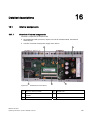
Detailed descriptions ............................................................................................................................. 115
16.1
16.1.1
16.1.2
16.1.3
16.1.3.1
16.1.3.2
16.1.3.3
16.1.3.4
16.1.3.5
16.1.3.6
16.1.3.7
16.1.3.8
16.1.4
16.1.4.1
16.1.4.2
16.1.4.3
Internal components.................................................................................................................. 115
Overview of internal components.............................................................................................. 115
Technical features of the motherboard ..................................................................................... 116
External ports ............................................................................................................................ 116
Overview ................................................................................................................................... 116
COM1/2 ..................................................................................................................................... 117
DVI-I .......................................................................................................................................... 117
Ethernet..................................................................................................................................... 118
USB ........................................................................................................................................... 119
PROFIBUS................................................................................................................................ 119
PROFINET ................................................................................................................................ 120
CAN bus .................................................................................................................................... 121
Internal ports ............................................................................................................................. 121
Overview ................................................................................................................................... 121
Compact Flash card interface ................................................................................................... 122
PCI-104 or PC/104-Plus interface (PCI part) ............................................................................ 122
16.2
16.2.1
16.2.2
16.2.3
16.2.4
16.2.5
16.2.6
16.2.7
16.2.8
16.2.9
16.2.10
BIOS Setup ............................................................................................................................... 123
Overview ................................................................................................................................... 123
Starting BIOS Setup.................................................................................................................. 124
BIOS Setup menus ................................................................................................................... 125
Main menu................................................................................................................................. 126
Advanced Menu ........................................................................................................................ 132
Security menu ........................................................................................................................... 135
Boot menu ................................................................................................................................. 136
Version menu ............................................................................................................................ 139
Exit Menu .................................................................................................................................. 140
Default BIOS Setup entries ....................................................................................................... 141
16.3
16.3.1
16.3.2
16.3.2.1
System resources ..................................................................................................................... 143
Currently allocated system resources....................................................................................... 143
System resources used by the BIOS/DOS ............................................................................... 143
PCI Interrupt Lines .................................................................................................................... 143
16.4
16.4.1
16.4.2
16.4.3
16.4.4
16.4.5
16.4.6
16.4.7
I/O Address Areas..................................................................................................................... 145
Overview of the internal module registers................................................................................. 145
Watchdog enable register / 066h select register (read/write, address 062h) ........................... 145
Watchdog trigger register (read only, address 066h) ............................................................... 146
CAN base address register (write only, address 066h) ............................................................ 146
Output register user LED L1/L2 (read/write, address 404Eh)................................................... 147
Battery status tab (read-only, address 50Fh)............................................................................ 148
SRAM address register ............................................................................................................. 148
16.5
16.5.1
16.5.1.1
16.5.1.2
16.5.2
16.5.2.1
16.5.3
CP 1616 onboard communications processor .......................................................................... 149
Introduction ............................................................................................................................... 149
Network connections................................................................................................................. 149
Typical Communication Partners .............................................................................................. 149
Firmware Loader ....................................................................................................................... 151
Loading firmware....................................................................................................................... 151
Further actions in STEP 7/NCM PC.......................................................................................... 153
Appendix................................................................................................................................................ 155
A.1
Guidelines and declarations...................................................................................................... 155
A.2
Certificates and approvals......................................................................................................... 156
A.3
Service and support .................................................................................................................. 157
SIMATIC IPC427C
Operating Instructions, 10/2010, A5E02414743-03
Table of contents
B
ESD guidelines ...................................................................................................................................... 159
B.1
C
ESD Guidelines..........................................................................................................................159
List of abbreviations............................................................................................................................... 161
C.1
Abbreviations .............................................................................................................................161
Glossary ................................................................................................................................................ 167
Index...................................................................................................................................................... 179
SIMATIC IPC427C
Operating Instructions, 10/2010, A5E02414743-03
7
Table of contents
8
SIMATIC IPC427C
Operating Instructions, 10/2010, A5E02414743-03
Introduction
1.1
1
Preface
Objective of this documentation
These operating instructions contain all the information you need for commissioning and
operation of the SIMATIC IPC427C.
It is intended both for programming and testing personnel who commission the device and
connect it with other units (automation systems, programming devices), as well as for service
and maintenance personnel who install add-ons or carry out fault/error analyses.
Basic knowledge requirements
A solid background in personal computers and Microsoft operating systems is required to
understand this manual. General knowledge in the field automation control engineering is
recommended.
Scope of validity of this document
The operating instructions are valid for all supplied variants of SIMATIC IPC427C and
describe the delivery state as of October 2010.
Position in the information landscape
The documentation for the SIMATIC IPC427C includes the following sections:
● SIMATIC IPC427C, Operating Instructions (Compact)
● SIMATIC IPC427C, Operating Instructions
The documentation is supplied in German and English with the device in electronic form as a
PDF file on the "Documentation and Drivers" CD/DVD.
Conventions
The term "PC" or "device" is sometimes used to refer to the SIMATIC IPC427C product in
this documentation. The abbreviation "CP" stands for CP 1616 onboard.
SIMATIC IPC427C
Operating Instructions, 10/2010, A5E02414743-03
9
Introduction
1.2 Guideline to the Operating Instructions
History
Currently released versions of this operating manual:
1.2
Edition
Comment
04/2009
First edition
08/2009
Variants with PROFINET
10/2010
Variants with Windows 7 Ultimate / Windows Embedded Standard 7
Guideline to the Operating Instructions
Contents format
Table of Contents
Contents
Organization of the documentation, including the index of pages and chapters
Introduction
Purpose, layout and description of the important topics.
Safety instructions
Refers to all the valid technical safety aspects which have to be adhered to while installing,
commissioning and operating the product/systemin and in reference to statutory
regulations.
Description
Fields of application, the features and the structure of the product/system
Application planning
Aspects of storage, transport, environmental and EMC conditions to be considered in the
preparatory stage
Mounting
Product installation options and installation instructions
Connecting
Options of connecting the product and connection instructions
Commissioning
Commissioning the product/system.
Integration
Options of integrating the product into existing or planned system environments/networks
Functions
Monitoring and display functions
Expansions / configurations
Procedure for installing expansion devices (memory, modules).
Maintenance and service
Replacement of hardware components, restoring and setup of the operating system,
installation of drivers and software
Alarm, error and system
messages
Error messages from booting
Troubleshooting
Problems, cause, remedy
Technical specifications
General specifications in compliance with relevant standards and current/voltage values
Dimension drawings
Dimensions of the device and of modules
Detailed descriptions
Structure, function and features of vital components, distribution of system resources and
use of the BIOS Setup routine
Appendix
Guidelines and certifications, service and support, notes on retrofitting.
ESD guidelines
General ESD guidelines.
10
SIMATIC IPC427C
Operating Instructions, 10/2010, A5E02414743-03
Safety Instructions
2.1
2
General safety instructions
CAUTION
Please observe the safety instructions on the back of the cover sheet of this
documentation. You should not expand your device unless you have read the relevant
safety instructions.
This device is compliant with the relevant safety measures to IEC, EN, VDE, UL, and CSA. If
you have questions about the validity of the installation in the planned environment, please
contact your service representative.
Repairs
Only authorized personnel are permitted to repair the device.
WARNING
Unauthorized opening of and improper repairs to the device may result in substantial
damage to equipment or endanger the user.
System expansions
Only install system expansion devices designed for this device. The installation of other
expansions can damage the system and violate the radio-interference suppression
regulations. Contact your technical support team or where you purchased your PC to find out
which system expansion devices may safely be installed.
CAUTION
If you install or exchange system expansions and damage your device, the warranty
becomes void.
SIMATIC IPC427C
Operating Instructions, 10/2010, A5E02414743-03
11
Safety Instructions
2.1 General safety instructions
Battery
This device is equipped with a Lithium battery. Batteries may only be replaced by qualified
personnel.
CAUTION
There is the risk of an explosion if the battery is not replaced as directed. Replace the
battery only with the same type or with an equivalent type recommended by the
manufacturer. Dispose of used batteries in accordance with local regulations.
WARNING
Risk of explosion and release of harmful substances!
For this reason, do not burn lithium batteries, do not solder on the cell body, do not open,
do not short circuit, do not reverse polarity, do not heat above 100°C, dispose of correctly,
and protect against direct sunlight, dampness and dew.
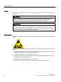
ESD directives
Modules containing electrostatic sensitive devices (ESDs) can be identified by the following
label:
Strictly follow the guidelines mentioned below when handling modules which are sensitive to
ESD:
● Always discharge your body´s static electricity before handling modules that are sensitive
to ESD (for example, by touching a grounded object).
● All devices and tools must be free of static charge.
● Always pull the mains connector and disconnect the battery before installing or removing
modules which are sensitive to ESD.
● Handle modules fitted with ESDs only by their edges.
● Do not touch any connector pins or conductors on modules containing ESDs.
12
SIMATIC IPC427C
Operating Instructions, 10/2010, A5E02414743-03
3
Description
3.1
Overview
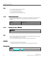
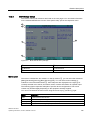
The SIMATIC IPC427C provides high-level industrial performance.
● Compact design
● Maintenance-free operation
● High degree of ruggedness
Figure 3-1
3.2
SIMATIC IPC427C
Applications
The device provides industrial PC systems for high-performance and space-saving
applications in particular in the field of machine, systems and switchgear cabinet
engineering:
● Measuring and controlling of process and machine data (for example, automated washing
systems, assembling machines, packaging machines)
● Operating and visualization tasks with separate display / monitor solutions (information
terminals, large-scale displays in automotive production)
● Data logging and processing (for example, system data logging, distributed process
control)
SIMATIC IPC427C
Operating Instructions, 10/2010, A5E02414743-03
13
Description
3.3 Features
3.3
Features
Basic data
Installation / mounting
Installation on a DIN rail
Wall mounting
Vertical mounting
Hanging assembly
Processor
Intel Celeron M 1.2 GHz, 800 MHz FSB, 1 MB SLC or
Intel Pentium Core 2 Solo 1.2 GHz, 800 MHz FSB,
3 MB SLC or
Intel Pentium Core 2 Duo 1.2 GHz, 800 MHz FSB, 3 MB
SLC
512 MB DDR3-SDRAM SODIMM
1 GB DDR3-SDRAM SODIMM
2 GB DDR3-SDRAM SODIMM
4 GB DDR3-SDRAM SODIMM
Main memory
Free slots for expansion
Up to 3 x PCI/104 modules or 3x PC/104-Plus module (PCI
bus only);
installed with expansion frame
Graphics
Integrated Intel GMA4500 graphics
CRT resolution of 640x480 pixels up to 1920x1200
pixels
DVI resolution of 640x480 pixels up to 1920x1200 pixels
32 to 256 MB graphics memory is taken from main
memory (dynamic UMA)
Power supply
24 VDC (19.2 to 28.8 V) max. 4 A
Conditions of use
Operation without fan
CompactFlash card
256 MByte optional or
2 GB optional or
4 GB optional or
8 GB optional
Hard disk
≥ 80 GB SATA HD 2.5" optional
SSD (Solid State Disk)
≥ 32 GB optional
Floppy/CD-ROM drive
Connected via external USB port
USB stick
Connected via external USB port
Drives and storage media
Ports
Serial
COM1 (RS232)
COM2 (RS232); optional
14
Graphics
DVI-I: combined DVI and VGA
USB
4 x USB 2.0 high current
Ethernet
2 x RJ 45 (10/100/1000 Mbit/s) or
1x RJ 45 (10/100/1000 Mbit/s) for PROFINET variants
PROFIBUS DP
12 Mbps (electrically isolated,
compatible to CP 5611), optional
SIMATIC IPC427C
Operating Instructions, 10/2010, A5E02414743-03
Description
3.3 Features
Basic data
PROFINET
3 x RJ 45 (10/100 Mbit/s), CP 1616 onboard; optional
CAN interface
Optional
Keyboard, mouse
Connected via external USB port
Monitoring and safety functions
Temperature
When permitted temperature range is exceeded
Warnings can be analyzed by application program
(local, via LAN)
Watchdog
Monitoring function for program execution
Restart can be parameterized in the event of a fault
Warnings can be analyzed by application program
(local, via LAN)
LED display
4 LEDs (or 5 for PROFINET variants) for displaying system
states
2 of these can be programmed by the user1
Transient voltage interruption
Up to 15 ms buffer time at full load
Buffer memory
2 MB battery-buffered SRAM1
Software
Operating systems
Available
Without
Windows Embedded Standard 2009
Windows Embedded Standard 7 (32-bit)
Windows XP Professional MUI SP3 preinstalled 2
Windows 7 Ultimate MUI2, (32 bit)
Project-specific
LINUX
QNX
VxWorks
Others on request
RMOS V3.50 (can be ordered separately)
1 For additional information about addressing the LEDs or the SRAM under a Windows
operating system, refer to section Output register user LED L1/L2 (read/write, address
404Eh) (Page 147). Example programs for addressing the LEDs on Windows operating
systems and on RMOS3 are available on the FAQ pages at Siemens Customer Support
Industry Automation and Drive Technologies - Homepage
(http://www.siemens.com/automation/service&support).
MUI: Multi Language User Interface; 5 languages (English, German, French, Spanish,
Italian)
2
SIMATIC IPC427C
Operating Instructions, 10/2010, A5E02414743-03
15
Description
3.4 Windows Embedded Standard 2009
The following additional languages can be installed from the Operating System
Recovery DVD:
Language
Windows XP
Windows 7
X
X
German
English
X
French
X
X
Italian
X
X
Spanish
X
X
Japanese
X
X
Chinese (Hong Kong)
X
X
Chinese (simplified)
X
X
Chinese (Taiwan)
3.4
X
Korean
X
Russian
X
X
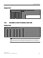
Windows Embedded Standard 2009
The supplied Windows Embedded Standard has the product version 2009. The overview
shows the basic device functions under Windows Embedded Standard 2009:
16
Function
Version HDD / SSD
CompactFlash card version
Enhanced Write Filter (EWF)
In RAM RAM(REG)
In RAM RAM(REG)
SIMATIC IPC DiagBase
Available V1.2
Available V1.2
Pagefile
Deactivated in favor of the EWF
Deactivated in favor of the EWF
System Restore Core
Deactivated in favor of the EWF
Deactivated in favor of the EWF
File based Writefilter (FBWF)
Available
Available
Registryfilter
Available
Available
Device Update Agent (DUA)
Available
Available
HORM
Available
Available
Telnet Server
Available
Available
Windows Backup
Available
Available
User Mode Driver Framework
(UMDF)
Available
Available
MUI
GER/FRA/ITA/SPA
Default language: English
GER
default language: English
Administrator Account
Available
Available
User Account
Available
Available
Explorer Shell
Available
Available
Internet Explorer (IE)
Available, IE7
Available, IE7
Internet Information Server (IIS)
Available V5.1
Available V5.1
Terminal Services
Available
Available
Bluetooth
Available
Available
SIMATIC IPC427C
Operating Instructions, 10/2010, A5E02414743-03
Description
3.4 Windows Embedded Standard 2009
Function
Version HDD / SSD
CompactFlash card version
Wireless Network Support
Available
Available
Windows Firewall
Available
Available
Windows Security Center
Available
Available
MSN Explorer
Available
Not available
Outlook Express
Available
Available
Administrative Tools
Available
Available
SMS Advanced Client
Available
Not available
Remote Desktop
Available V6.0
Available V6.0
Remote Assistance
Available
Available
.NET Framework
Available, V3.5
Not available
ASP.NET
Available, V3.5
Not available
Windows .NET Messenger
Available V4.7
Available V4.7
Code pages/User
Location/Keyboard
Available
Selection available
Disk Management Services
Available
Available
Windows Installer Service
Available V3.1
Available V3.1
Class Installer
Available
Available
CoDevice Installer
Available
Available
Windows Movie Maker
Available V 2.1
Not available
Media Player
Available, V11.0
Available, V11.0
Windows Media Player Tour
Available
Not available
DirectX
V9.0c
V9.0c
Accessories
Available
Available
Help files for all components
Available
Not available
Games
Available
Not available
Fonts
316
118
Windows XP Tour
Available
Not available
Microsoft Silverlight
Available V 1.0
Available V 1.0
NetMeeting
Available V 3.1
Available V 3.1
Note
Activation of "HORM" and creation of a "Hiber File"
When "HORM" is activated, the "Hibernate" function can be used for Windows Embedded
Standard 2009:
EWFMGR C: /activatehorm
"Hibernate" is activated following a restart. The system then always boots from this file.
SIMATIC IPC427C
Operating Instructions, 10/2010, A5E02414743-03
17
Description
3.5 Windows Embedded Standard 7
3.5
Windows Embedded Standard 7
The overview shows the most important device functions under Windows Embedded
Standard 7:
18
Function
Version HDD / SSD
Compact Flash card version
.Net Framework
Available, V3.5
Available, V3.5
Accessories
Available
Available
Aero background
Available
Available
Backup and Restore
Available
Available
Bluetooth
Available
Available
Dialog box filter
Available
Available
DirectX and Windows Device
Experience
Available, V11
Available, V11
Domain services
Available
Available
Driver database
Available
Not available
Driver frameworks
Available
Available
Encrypted File System (EFS)
Available
Available
Enhanced Write Filter
Available
Available
Fax and Scan
Available
Available
File Based Write Filter (FBWF)
Available
Available
Fonts
134
48
Help and Support Engine
Available
Available
Hibernate Once Resume Many
(HORM-EEF)
Available
Available
Image Mastering API V2
Available
Available
IME Base Components
Available
Available
Internet Explorer
Available, IE 8
Available, IE 8
Internet Information Server (IIS)
Available,V7.0
Available, V7.0
Language (Standard)
English 1)
English 1)
Mobility Center
Available
Available
Network and Sharing Center
Available
Available
Network Diagnostics
Available
Available
Pagefile
Available
Available
Printing Utilities and Management
Available
Available
Registry Filter
Available
Available
Remote Assistance
Available
Available
Remote Client
Available
Available
Remote Desktop
Available
Available
SIMATIC IPC DiagBase
Available, V1.4
Available, V1.4
Speech
Available
Not available
System Management
Administrative Tools
Available
Available
Telnet Server
Available
Available
User Account Control
Available
Available
SIMATIC IPC427C
Operating Instructions, 10/2010, A5E02414743-03
Description
3.6 Design
Function
Version HDD / SSD
Compact Flash card version
Windows Explorer Shell
Available
Available
Windows Firewall
Available
Available
Windows Installer
Available
Available
Windows Media Player
Available, V12
Available, V12
Windows PowerShell 2.0
Available
Available
Windows Search and Natural
Language 6
Available
Available
Windows Security Center
Available
Available
Windows Update
Available
Available
Wireless Networking
Available
Available
1)
Please note the license terms for Windows Embedded Standard 7.
See also
Language selection in Windows Embedded Standard 7 (Page 46)
3.6
Design
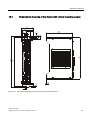
3.6.1
External Design
Device components
Pos
Description
①
Cover plate for Compact Flash module
②
Connection elements
③
Status displays
SIMATIC IPC427C
Operating Instructions, 10/2010, A5E02414743-03
19
Description
3.6 Design
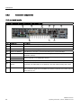
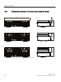
3.6.2
Connection components
Ports and power supply
Location of connection elements (version with PROFIBUS or CAN)
Pos
Designation
Description
①
24 VDC
Connection for a 24 V DC power supply
②
DVI/VGA
DVI/VGA connection for CRT or LCD monitor with DVI interface
③
USB
4 USB 2.0 connections, high-speed / low current
④
PN/IND. ETHERNET
RJ45 Ethernet connection 1 (exclusive PCI interrupt) for 10/100/1000 Mbps
⑤
PN/IND. ETHERNET
RJ45 Ethernet connection 2 (shared PCI interrupt) for 10/100/1000 Mbps (not for
PROFINET versions)
⑥
PROFIBUS DP/MPI
CAN fieldbus
PROFIBUS DP/MPI interface (RS 485 electrically isolated), 9-pin D-Sub socket or CAN
field bus (optional; not for PROFINET variants)
⑦
COM1
Serial port (RS232) 9-pin D-Sub connector
⑧
USB strain-relief
fastener
The USB strain relief must be fastened to the device enclosure with an oval-head screw
(M4 thread). The USB cables can be fastened to the strain-relief assembly with a cable
tie.
⑨
PE terminal
The PE terminal (M4 thread) must be connected to the protective ground conductor of the
plant, in which the device is to be installed. The minimum conductor cross-section may not
be less than 2,5 mm2.
20
SIMATIC IPC427C
Operating Instructions, 10/2010, A5E02414743-03
Description
3.6 Design
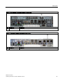
Location of the connection elements (second COM interface)
Item
Designation
Description
①
COM2
Serial port (RS232) 9-pin D-Sub connector
Location of connection elements (version with PROFINET)
Item
Designation
Description
⑥
PROFINET
CP 1616 onboard interface, three RJ45 jacks (optional product version)
SIMATIC IPC427C
Operating Instructions, 10/2010, A5E02414743-03
21
Description
3.6 Design
3.6.3
Operator controls
On/Off switch
CAUTION
The On/Off switch does not disconnect the device from the supply voltage.
Position of on/off switch
Pos
①
Description
The on/off switch turns off the output voltages of
the power supply but not disconnect from the
supply system.
The delivery condition is: On/Off switch turned
off.
22
SIMATIC IPC427C
Operating Instructions, 10/2010, A5E02414743-03
Description
3.6 Design
3.6.4
Status displays
Status displays
LED
Meaning
LED
Description
PWR
Power supply
OFF
GREEN
Standby mode
Supply voltage available
WD
Watchdog status display
OFF
GREEN
Watchdog disabled Watchdog
enabled, monitoring time not
expired
Watchdog enabled, monitoring
time expired
L1
User LED L1
OFF
Can be controlled by user
YELLOW programs1
RED
SF
Group errors
RED
L2
User LED L2
OFF
Can be controlled by user
YELLOW programs1
GREEN
RED
RUN/STOP RUN
STOP
Can be controlled by controller
program (e.g. WinAC)1
GREEN
Can be controlled by controller
YELLOW program (e.g. WinAC)1
1 For additional information about addressing the LEDs or the SRAM under a Windows
operating system, refer to section Output register user LED L1/L2 (read/write, address
404Eh) (Page 147). Example programs for addressing the LEDs on Windows operating
systems and on RMOS are available on the FAQ pages at Siemens Customer Support
Industry Automation and Drive Technologies - Homepage
(http://www.siemens.com/automation/service&support).
SIMATIC IPC427C
Operating Instructions, 10/2010, A5E02414743-03
23
Description
3.6 Design
PROFINET status display (additional display for PROFINET variants)
PROFINET status display
LED
Meaning
LED
Description
SF PROFINET
Status display for
CP 1616 onboard
OFF
RED: Flashes slowly
CP not available
CP disabled
No error, communication
established
Charging in progress
Link status error
I/O controller: I/O device
cannot be addressed
I/O controller: Redundant IP
address
RED: Flashes rapidly Exception error: diagnostics via
Web or SNMP is no longer
possible
RED
Diagnostics information
available
No communication
established.
Virtual status displays
The two "virtual" CP 1616 LEDs are only visible in the SIMATIC software and can be read via SNMP.
PROFINET
24
Virtual LEDs
RUN
CP is active
STOP
CP is in the stop state
Flashes
The states "flashes slowly" or
"flashes rapidly" do not exist.
SIMATIC IPC427C
Operating Instructions, 10/2010, A5E02414743-03
Application planning
4.1
4
Transport
Despite the device's rugged design, its internal components are sensitive to severe
vibrations or shock. You must therefore protect the device from severe mechanical stress
when transporting it.
You should always use the original packaging for shipping and transporting the device.
CAUTION
Risk of damage to the device!
If you are transporting the device in extreme weather conditions with large fluctuations in
temperature, care must be take to ensure that no moisture forms on or in the device
(condensation).
If condensation has developed on the device, wait at least 12 hours before you switch it on.
4.2
Unpacking and checking the delivery unit
Unpacking the device
Note the following when unpacking the unit:
● It is advisable not to dispose of the original packing material. Keep it in case you have to
transport the unit again.
● Please keep the documentation in a safe place. It is required for initial commissioning and
is part of the device.
● Check the delivery unit for any visible transport damage.
● Verify that the shipment contains the complete unit and your separately ordered
accessories. Please inform your local dealer of any disagreements or transport damages.
SIMATIC IPC427C
Operating Instructions, 10/2010, A5E02414743-03
25
Application planning
4.2 Unpacking and checking the delivery unit
Noting the device identification data
The device can be identified uniquely with the help of these numbers in case of repairs or
theft.
Enter the data in the following table:
Serial number
S VP ...
Order number of the device
6ES 7647-7B ...
Microsoft Windows Product Key
Ethernet address 1
Ethernet address 2 (not for PROFINET versions)
CP 1616 onboard MAC Address Layer 2 (only for
PROFINET variants)
CP 1616 onboard MAC address PROFINET (only for
PROFINET variants)
You can find the corresponding data here:
● Serial number: The serial number is available on the rating plate on the right side of the
device.
● Order number of the device: The order number is located on the rating plate.
● Ethernet address: The Ethernet address of the device is available in your BIOS Setup (F2
function key) under Main > Hardware Options
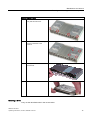
● Microsoft Windows "Product Key" from the "Certificate of Authenticity" (COA): The COA
label is attached only to the rear panel of devices with pre-installed Windows Embedded
Standard 2009, Windows Embedded Standard 7, Windows XP Professional, or
Windows 7 Ultimate.
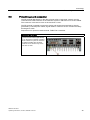
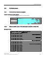
Examples for COA-Labels
26
Figure 4-1
COA label for Windows Embedded Standard 2009 and Windows Embedded Standard 7
Figure 4-2
COA label for Windows XP Pro for Embedded Systems
SIMATIC IPC427C
Operating Instructions, 10/2010, A5E02414743-03
Application planning
4.3 Ambient and Environmental Conditions
4.3
Ambient and Environmental Conditions
When you plan your project, you should make allowances for:
● The climatic and mechanical environmental conditions specified in the specifications
given in your operating instructions.
● The device is approved for operation in closed rooms only.
● Avoid extreme ambient conditions. Protect the device against dust, moisture and heat.
● Do not place the device in direct sunlight.
● Ensure that the distance to other components or the sides of cabinets is at least 50 mm
above and 100 mm below the device.
● Do not cover the ventilation slots of the device.
● Always observe the mounting positions permitted for this device.
● The connected or installed I/O must not generate a reverse voltage greater than 0.5 V in
the device.
SIMATIC IPC427C
Operating Instructions, 10/2010, A5E02414743-03
27
Application planning
4.3 Ambient and Environmental Conditions
28
SIMATIC IPC427C
Operating Instructions, 10/2010, A5E02414743-03
5
Installing/mounting
5.1
Permitted mounting positions
NOTICE
The device is approved for operation in closed rooms only.
Ensure that there is a minimum clearance to the other components or the walls of a
housing:
Below at least 100 mm
Above at least 50 mm
Horizontal (preferred position)
Permitted temperatures
Operation with hard disk:
with up to 3 expansion modules
(max. load 9 W): +5 to +40°C
Operation with CompactFlash card and/or SSD drive:
with up to 3 expansion modules
(max. load 9 W): 0 to +45°C
with up to 3 expansion modules
(max. load 9 W) in RAL: 0 to +50°C
Operation with Compact Flash cards:
without expansion modules in RAL: 0 to +55°C
Vertical
(power supply at the top)
Operation with hard disk:
with up to 3 expansion modules
(max. load 9 W): +5 to +40°C
With installed Compact Flash card:
without expansion modules: 0 to +45°C
Operation with CompactFlash card and/or SSD drive:
with up to 3 expansion modules
(max. load 9 W) in RAL: 0 to +45°C
Operation with Compact Flash cards:
with up to 3 expansion modules
(max. load 9 W) in RAL: 0 to +50°C
Notes:
When mounted on a DIN rail, the device should be secured
to prevent shifting (e.g. with a DIN rail ground terminal).
SIMATIC IPC427C
Operating Instructions, 10/2010, A5E02414743-03
29
Installing/mounting
5.1 Permitted mounting positions
Suspended
Operation with CompactFlash card and/or SSD drive and
without expansion modules:
0 to +40°C
Note:
Mounting brackets are required if the device is suspended.
Upright mounting
Permitted temperatures
Operation with hard disk:
with up to 3 expansion modules
(max. load 9 W): +5 to +40°C
Operation with CompactFlash card:
Without expansion modules: 0 to +45°C
Operation with CompactFlash card and/or SSD:
with up to 3 expansion modules
(max. load 9 W) in RAL: 0 to +45°C
Operation with Compact Flash cards:
with up to 3 expansion modules
(max. load 9 W) in RAL: 0 to +50°C
RAL = Restricted Access Location
(e.g. installation of the unit in a lockable cabinet)
NOTICE
The safety and installation instructions for the expansion modules should be followed if the
device is expanded with PCI-104 / PC/104-plus modules.
If necessary, the device should be installed in an enclosure that meets the requirements of
paragraphs 4.6 and 4.7.3 of IEC/UL/EN/DINEN60950-1.
30
SIMATIC IPC427C
Operating Instructions, 10/2010, A5E02414743-03
Installing/mounting
5.2 Mounting information
5.2
Mounting information
Before you install the device, read the following mounting instructions.
NOTICE
Adhere to the SIMATIC assembly guidelines and the relevant DIN/VDE requirements or the
country-specific regulations when mounting in switching cabinets.
NOTICE
Ensure that the device is classified as "Open Type" when using the device in the area of
Industrial Control Equipment (UL508). A UL508 conform enclosure is therefore a
mandatory requirement for approval or operation according to UL508.
5.3
Mounting the device
Mounting methods
SIMATIC IPC427C can be mounted on DIN rails, with mounting brackets and in an upright
position.
5.4
Mounting on DIN rails
Mounting the device on DIN rails
Note
Use of Siemens 35 mm standard mounting rail is recommended.
SIMATIC IPC427C
Operating Instructions, 10/2010, A5E02414743-03
31
Installing/mounting
5.4 Mounting on DIN rails
Steps for mounting on DIN rails
1.
Set the device inclined on the
upper DIN rail.
2.
Swing the device fully onto the rails
until both clamps completely latch.
Note
To ensure secure mounting on vertical mounting rails, a DIN rail ground terminal should be
mounted beneath the device.
NOTICE
The rails are secured to a wall or cabinet similar to mounting with mounting brackets.
Ensure that the wall or ceiling can hold four times the total weight of the device (including
the rails and additional expansion modules). Also see section Mounting with mounting
brackets (Page 33).
Removing the device from the DIN rail
● Push down the device until the clamps release it.
● Swing the device out of the rails.
32
SIMATIC IPC427C
Operating Instructions, 10/2010, A5E02414743-03
Installing/mounting
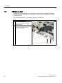
5.5 Mounting with mounting brackets
5.5
Mounting with mounting brackets
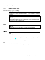
Removing mounting clamps from the device
Two mounting clamps are factory installed on the device for DIN rail mounting. These need
to be removed before mounting the mounting brackets.
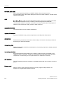
Steps for removing the mounting clamps
Remove the four screws ② and
the two mounting clamps ① from
the back of the device.
Installing brackets on the device
Two mounting brackets are included in the scope of delivery. They can be installed on the
device with four screws supplied.
Steps for installing the mounting brackets
Install the mounting brackets on the
device.
Note
Required tools
You need a TORX T20 screwdriver to remove the mounting clamps and mount the mounting
brackets.
SIMATIC IPC427C
Operating Instructions, 10/2010, A5E02414743-03
33
Installing/mounting
5.5 Mounting with mounting brackets
Mounting/demounting the device
The dimensions of the device with mounting brackets are listed under Dimension drawings of
the device with mounting brackets (Page 109).
Mounting examples
Material
Bore diameter
Mounting
Concrete
8 mm diameter
60 mm depth
Dowel: 8 mm diameter
50 mm length
Screws: 4 mm diameter
50 mm length
Plasterboard
(min. 13 mm thick)
14 mm diameter
Gravity toggle: 4 mm diameter
50 mm length
Metal
(min. 2 mm thick)
5 mm diameter
Metal screws M 4: 4 mm diameter
15 mm length
WARNING
Ensure that the wall or ceiling can hold four times the total weight of the device (including
the cabinet brackets and additional expansion modules).
34
SIMATIC IPC427C
Operating Instructions, 10/2010, A5E02414743-03
Installing/mounting
5.6 Upright mounting
5.6
Upright mounting
With the available optional vertical mounting kit you have the possibility to implement a place
saving installation.
Mounting the vertical mounting bracket onto the device
① Device
② Screws
③ Vertical mounting bracket
Note
Information on installation and operation is available in the supplement of the
accessories.
SIMATIC IPC427C
Operating Instructions, 10/2010, A5E02414743-03
35
Installing/mounting
5.6 Upright mounting
36
SIMATIC IPC427C
Operating Instructions, 10/2010, A5E02414743-03
Connecting
6.1
6
Connecting peripheral equipment
NOTICE
Connect only peripheral devices approved for industrial applications conforming to
EN 61000-6-2 / IEC 61000-6-2.
Note
Hot-plug peripherals (USB) may be connected while the PC is in operation.
CAUTION
Peripheral devices that are incapable of hot-plugging may only be connected after the
device has been disconnected from the power supply.
CAUTION
Strictly adhere to the specifications for peripheral equipment.
Note
A DVI or CRT monitor should be connected and switched on when the device boots in order
for it to be correctly detected by the BIOS and the operating system. The screen may
otherwise remain dark.
NOTICE
The connected or built-in peripherals, such as USB drives, should not introduce a counter
emf into the device.
Generation of reverse voltage greater than 0.5 V to ground on + 3.3 VDC / + 5 VDC / + 12
VDC at a connected or installed component can prevent normal operation or destroy
components of the device.
SIMATIC IPC427C
Operating Instructions, 10/2010, A5E02414743-03
37
Connecting
6.2 Connecting the 24 V DC power supply
6.2
Connecting the 24 V DC power supply
To be noted before you connect the device
Note the following in order to operate the device safely and according to regulation:
WARNING
The device should only be connected to a 24V DC power supply which satisfies the
requirements of safe extra low voltage (SELV).
If the device is used on a wall, in an open rack or other similar locations, an NEC Class 2
current source is required in order to meet the UL requirements (UL 60950-1). In all other
cases (IEC / EN / DIN EN 60950-1) either a current source of limited output (LPS = Low
Power Source), or a line-side fuse or a line-side circuit breaker is necessary. The power
needs to be limited to a value below 4.16 A. The fuse value required: Max. 4 A.
Use the special plug supplied to connect the supply voltage. Connect the PE conductors as
described in the next section.
NOTICE
The permitted cable cross-section for the 24 VDC connection is 0.75 mm2 to 2.5 mm2.
NOTICE
If a CompactFlash card is used in the device, make sure that the card is seated correctly
before you connect it.
Connecting
Steps for connecting the device to the 24 V DC power supply
1.
Switch off the 24 V DC power source.
2.
Connect the power supply using the plug
(included in the scope of delivery).
3.
Connect the PE conductor.
3LQ
38
0LQ
SIMATIC IPC427C
Operating Instructions, 10/2010, A5E02414743-03
Connecting
6.3 Protective ground connection
6.3
Protective ground connection
The PE terminal (M4 thread) on the device (large surface, large-area contact) must be
connected to the PE conductor on the cabinet or system in which the PC is to be installed.
The conductor cross-section must not be less than 2.5 mm2.
The PE terminal is needed to protect the device and ensures that interference signals
generated by external power cables, signal cables or cables to the I/O modules are safely
discharged to earth.
Required tool for protective earth terminal: TORX T20 screwdriver
Protective earth terminal
Connect the PE terminal (M4 thread)
① on the device to the PE conductor
on the cabinet or system in which the
PC will be installed. The minimum
conductor cross-section may not be
less than 2,5 mm2.
SIMATIC IPC427C
Operating Instructions, 10/2010, A5E02414743-03
39
Connecting
6.4 USB strain-relief
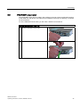
6.4
USB strain-relief
The USB strain-relief provided as an accessory is used to prevent accidental loosening of
the USB cable from the device. A cable binder (not included in the package) is needed to
use this accessory.
To fix the USB strain relief, you will need a TORX T20 screwdriver.
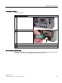
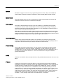
Attaching the USB strain relief
1. Fasten the USB strain-relief ① to the
device housing with an oval-head
screw (M4 thread).
2. Thread the cable tie ② through the
comb of the USB strain-relief to
clamp the USB cable.
40
SIMATIC IPC427C
Operating Instructions, 10/2010, A5E02414743-03
Connecting
6.5 PROFINET strain relief
6.5
PROFINET strain relief
The PROFINET strain relief provided in the package is used to prevent accidental loosening
of the cable from the device. One cable tie (not included in the scope of delivery) is required
for each interface.
To fix the PROFINET strain relief, you will need a TORX T10 screwdriver.
Attaching the PROFINET strain relief
1
Attach the PROFINET strain relief.
2
Attach the cable using the cable tie.
SIMATIC IPC427C
Operating Instructions, 10/2010, A5E02414743-03
41
Connecting
6.5 PROFINET strain relief
42
SIMATIC IPC427C
Operating Instructions, 10/2010, A5E02414743-03
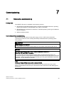
Commissioning
7.1
7
Note before commissioning
Factory state
The SIMATIC IPC427C is available in the following versions:
● With Windows Embedded Standard 2009 or Windows Embedded Standard 7 operating
system (pre-installed on CompactFlash card, SSD, or hard disk)
● With Windows XP Professional or Windows 7 Ultimate operating system (pre-installed on
SSD or hard disk)
● Without operating system
Connections before commissioning
Before connecting the device to the power supply, a DVI or CRT monitor should be
connected in order for it to be correctly detected by the BIOS and the operating system
during startup.
CAUTION
Risk of damage to the device
If condensation has developed, wait at least 12 hours before commissioning the device.
NOTICE
Windows Embedded Standard 2009 / Windows Embedded Standard 7:
Read the EWF and FBWF information
Two configurable write filters (Enhanced Write Filter and File Based Write Filter) are
provided on systems running Windows Embedded Standard 2009 and Windows Embedded
Standard 7. Please be aware of this when activating and using the EWF/FBWF information,
otherwise you may experience data loss.
Note
Setting up CompactFlash cards on the employed device
If you want to use CompactFlash cards with the device, they need to be set up on the
device. CompactFlash cards set up on other devices will not boot due to the differing drive
parameters.
SIMATIC IPC427C
Operating Instructions, 10/2010, A5E02414743-03
43
Commissioning
7.2 Commissioning - Windows Embedded Standard
7.2
Commissioning - Windows Embedded Standard
7.2.1
Basic commissioning - initial startup
Requirements
● The device is connected to the 24 VDC power supply.
● The equipotential bonding lines are wired.
● The connecting cables are properly inserted.
Setting up the operating system
After initial power up, the Windows Embedded Standard operating system that is preinstalled on the CompactFlash card, SSD, or hard disk is set up automatically on the
computer.
Proceed as follows:
1. Switch on the device using the On/Off switch. The device performs a power on self-test.
During the self-test, this message appears:
Press F2 go to Setup Utility or
Press ESC go to Boot Manager
2. Wait until this message is cleared, then follow the instructions on the screen.
NOTICE
The device may not be switched off at any time during the installation process.
Do not change the defaults in BIOS Setup, otherwise the operating system setup may
become corrupted.
3. Restart
After you have entered all the necessary information and the operating system is
configured,
you are prompted to restart the system. Respond to this prompt with Yes.
Note
Initial commissioning of Windows Embedded Standard 2009
System startup can take considerably longer than usual during initial commissioning of
Windows Embedded Standard 2009. Only a blue or black screen is displayed for several
minutes.
44
SIMATIC IPC427C
Operating Instructions, 10/2010, A5E02414743-03
Commissioning
7.2 Commissioning - Windows Embedded Standard
As of now, each time you power up the computer and complete the startup routine, the logon
window or user interface of the Windows Embedded Standard operating system is opened
immediately.
Note
Once you have completed initial commissioning, you should create an image of your system
partition in order to prevent data loss.
Switch off the device.
When you work with Windows Embedded Standard , always shut down the PC with the
command Start > Shut Down. You can then switch off the device with the power switch or by
disconnecting the power supply.
Note
The Enhanced Write Filter should be enabled following the installation of Windows
Embedded Standard on a CompactFlash card or SSD. When this is enabled, the device can
be switched off with the power switch by disconnecting the power supply.
7.2.2
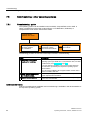
Setting up the language selection in Windows Embedded Standard 2009
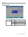
Windows Embedded Standard 2009 offers the option of selecting the menu and dialog
languages. You can select the German and English languages.
Setting up the language selection
Windows Embedded Standard 2009 is set up by default with English menu and dialog
language and US international keyboard layout. You can change the language in the Control
Panel by selecting:
Start > Settings > Control Panel >Regional and Language Options > Languages tab, Language used in menus and dialogs
field.
In addition to the menu and dialog language, select Regional and Language Options and set the default to non-Unicode
programs in the Advanced section.
SIMATIC IPC427C
Operating Instructions, 10/2010, A5E02414743-03
45
Commissioning
7.2 Commissioning - Windows Embedded Standard
7.2.3
Language selection in Windows Embedded Standard 7
Changing languages is possible using the Restore CD/DVD (forms part of the scope of
delivery). The CD/DVD contains the required language packages and help for changing the
system language.
Note
Note the license terms of Windows Embedded Standard 7
Please note the license terms for Windows Embedded Standard 7 and especially the
extended SIEMENS AG Software terms for Windows Embedded Standard 7.
You can find the license terms in the delivered document "MICROSOFT SOFTWARE
LICENSE TERMS for Windows Embedded Standard 7(E)" and in the system drive under
\Windows\System32\license.rtf.
Change system language
To change the language for Windows Embedded Standard 7, follow these steps:
Prerequisite:
The "Legacy USB Support" option has to be set to "Enabled" in the Advanced menu of the
BIOS so that the device can address a USB CD-ROM drive.
1. Connect a USB CD-ROM drive to the device.
2. Insert the Restore CD/DVD in the drive, restart the device and when the BIOS message:
Press <F2> to enter Setup or <ESC> to show Boot menu
appears, press the F2 key.
3. Select the Boot menu and move the entry "CD-ROM Drive" to the first position.
4. End the BIOS setup with the "Exit Saving Changes" entry.
46
SIMATIC IPC427C
Operating Instructions, 10/2010, A5E02414743-03
Commissioning
7.3 Commissioning - Windows XP Professional / Windows 7 Ultimate
5. Follow the on-screen instructions.
6. After selecting the menu dialog language of the Restore CD/DVD, select the menu entry
"Select language packages".
Depending on the current language setup, you have the following options in the "Select
language packages" menu:
– Display language settings
– Install language
– Change language
– Deinstall the "Non-system language"
Note
The "Install language or Deinstall language" process can take several minutes.
Note
The "Legacy USB Support" option has to be set to "Enabled" in the Advanced menu of
the BIOS so that the device can address a USB CD-ROM drive. Additional information
is available in the section .
7.3
Commissioning - Windows XP Professional / Windows 7 Ultimate
7.3.1
Basic commissioning - initial startup
Requirements
● The device is connected to the 24 VDC power supply.
● The equipotential bonding lines are wired.
● The connecting cables are properly inserted.
SIMATIC IPC427C
Operating Instructions, 10/2010, A5E02414743-03
47
Commissioning
7.3 Commissioning - Windows XP Professional / Windows 7 Ultimate
Setting up the operating system
On completion of initial power up, the Windows XP Professional or Windows 7 Ultimate
operating system that is pre-installed on the hard disk or SSD is set up automatically on the
computer.
Proceed as follows:
1. Switch on the device using the On/Off switch. The device performs a power on self-test.
During the self-test, this message appears:
Press F2 go to Setup Utility or
Press ESC go to Boot Manager
2. Wait until this message is cleared, then follow the instructions on the screen.
NOTICE
The device may not be switched off at any time during the installation process.
Do not change the defaults in BIOS Setup, otherwise the operating system setup may
become corrupted.
3. Automatic restart
After you have entered all necessary information and the operating system is configured,
the PC is automatically restarted and displays the user interface of the operating system.
Note
System startup can take considerably longer than usual for the initial commissioning.
As of now, each time you power up the computer and complete the startup routine, the user
interface of the Windows XP Professional / Windows 7 Ultimate operating system is opened
immediately.
Note
Once you have completed initial commissioning, you should create an image of your system
partition in order to prevent data loss.
Switch off the device.
When working with Windows XP Professional or Windows 7 Ultimate, always select Start >
Turn Off Computer... to shut down the PC. You can then switch off the device with the power
switch or by disconnecting the power supply.
48
SIMATIC IPC427C
Operating Instructions, 10/2010, A5E02414743-03
Commissioning
7.4 Windows XP, Windows 7 Security Center
7.3.2
Setting up language selection in Windows XP Professional / Windows 7
Ultimate
The Multilingual User Interface (MUI) allows you to change the menu and dialog language.
The English language and US keyboard layout are set up by default for the operating system
menus and dialogs. You can change the menu and dialog language as follows:
● On Windows XP Professional:
Start > Control Panel > Regional and Language Options
● On Windows 7:
Start > Control Panel > Regional and Language Options
7.4
Windows XP, Windows 7 Security Center
Warning from the Windows Security Center
A warning from the Windows Security Center appears the first time you switch on your
device. The Security Center checks the status of the device in regard to the three important
security aspects listed below. If a problem is detected (an outdated antivirus program, for
example), the Security Center issues a warning and makes recommendations on how you
can better protect the device.
● Firewall: The Windows Firewall adds protection to the device by blocking network or
Internet access to the device by unauthorized users. Windows checks if the device is
protected by a software firewall.
The firewall is enabled by default in the factory state.
● Antivirus software: Antivirus programs add protection to the device by searching for and
eliminating viruses and other security threats. Windows checks if a full-range, up-to-date
antivirus program is running on the device.
No antivirus software is installed in the factory state.
● Automatic updates: Using the Automatic Update feature allows Windows to regularly
search for the latest critical updates for the device and to install them automatically. This
feature is disabled in the factory state.
● Real-time protection (Windows 7 only): Windows Defender displays warnings if spyware
or possibly unwanted software is installed or executed on the computer. You will also
receive a warning if programs attempt to modify important Windows settings.
Configure the Security Center according to your requirements.
SIMATIC IPC427C
Operating Instructions, 10/2010, A5E02414743-03
49
Commissioning
7.5 Commissioning - other operating systems
7.5
Commissioning - other operating systems
7.5.1
Commissioning - guide
The operating system can be installed on the hard disk, CompactFlash card or SSD. A
variety of USB devices (hard disk, external floppy or CD-ROM drive, USB stick) or
CompactFlash cards can be used as boot media.
&RPPLVVLRQLQJ
6,0$7,&,3&&
6HOHFWLQJFUHDWLQJ
WKHERRWPHGLXP
IRULQVWDOODWLRQ
,QVWDOOLQJWKH
RSHUDWLQJV\VWHP
IURPWKHERRWPHGLXP
6HOHFWLQJWKHDFWLYH
ERRWPHGLXP
The following provides an overview of the steps involved in commissioning:
Steps
Description
1
In the BIOS Setup, select a suitable medium for booting the
operating system (CD-ROM drive, CompactFlash card, hard disk
or USB device). See Boot menu (Page 136).
Select and create a boot
medium for installation.
If no boot medium is available, one must be created based on
the instructions provided by the respective operating system
documentation.
You can use the SIMATIC IPC Image & Partition Creator tool to
create a bootable USB stick.
2
Install the operating system
on the boot medium.
Install the operating system based on the instructions provided
by the respective documentation.
3
Select final boot medium
In the BIOS Setup, select the medium on which the operating
system has been installed.
Additional information
Further information about installation and commissioning is available in the documentation of
the respective operating system.
50
SIMATIC IPC427C
Operating Instructions, 10/2010, A5E02414743-03
Integration into an Automation System
8.1
8
Overview
Options of integration in existing or planned system environments/networks:
Ethernet
The integrated Ethernet port (10/100/1000 Mbps) can also be used for communication and
for data exchange with automation devices such as SIMATIC S7.
For this purpose you require the "SIMATIC NET" software package.
PROFIBUS/MPI
The optional electrically isolated PROFIBUS interface (12 Mbps) can be used to interconnect
distributed field devices or for coupling to SIMATIC S7.
The "SOFTNET for PROFIBUS" software package is required for coupling to S7 automation
systems.
PROFINET
CP 1616 onboard enables the connection of industrial PCs to Industrial Ethernet. Only one
CP 1616 can be installed in a PG/PC. For more information, refer to section PROFINET
(Page 52) and to chapter CP 1616 onboard communications processor (Page 149).
Device driver CP 16xx.sys
The device driver supports implementation of the Windows network protocols for the
optionally available "CP 1616 onboard" Ethernet PROFINET controller on SIMATIC PCs.
When used with this driver, the PROFINET interface behaves in Windows similar to a 100
Mbit Ethernet interface with MAC address. The three RJ45 sockets are interconnected via
switch.
The drivers and documentation can be found in the user manual on the supplied
Documentation and Drivers CD/DVD.
PROFINET IO application
You can create, operate or configure PROFINET IO applications using the "Development Kit
DK-16xx PN IO". It must be installed in addition to the device driver CP 16xx.sys. This kit
and the documentation are available free of charge at the following Internet address:
Development Kit DK-16xx PN IO
(http://www.automation.siemens.com/net/html_00/produkte/040_cp_1616_devlopkit.htm)
SIMATIC IPC427C
Operating Instructions, 10/2010, A5E02414743-03
51
Integration into an Automation System
8.2 PROFINET
SIMATIC NET PC software
You can create, operate and configure SIMATIC installations using this software package.
For additional information, refer to the SIMATIC NET Manual Collection CD. The software
package and documentation are not included in the scope of delivery.
CAN
CAN interface (optional) for connection to CAN field bus systems.
RS232
The serial port can be used for data communication (via terminal applications, for example).
Additional information
Additional information is available in the catalog and the online ordering system Industrial
Automation and Drive Technologies (http://mall.automation.siemens.com).
8.2
PROFINET
CP 1616 onboard
The basic characteristics of the PCS 1616 onboard are:
● Optimized for PROFINET IO
● With Ethernet realtime ASIC ERTEC 400
● Three RJ45 sockets for connecting terminal devices or addition network components
● Integrated 3-port real-time switch
● Automatic hardware detection
CAUTION
A maximum of one CP 1616/1604 module can be installed in one PG/PC. If you want to
use an additional CP 1616/1604 module, the CP 1616 onboard option must be disabled
via the entry "Onboard Profinet" in the BIOS Setup under Advanced > Peripheral
Configuration.
52
SIMATIC IPC427C
Operating Instructions, 10/2010, A5E02414743-03
Integration into an Automation System
8.2 PROFINET
Additional documentation on PROFINET
Get an overview of the information available for PROFINET
(http://support.automation.siemens.com/WW/view/en/18880715/133300).
Document name
What is contained in this document?
This documentation is not included in the scope of delivery:
Getting Started
PROFINET IO Getting Started: Manual
Collection
The documents use concrete examples to provide
step-by-step instructions on how to commission a fully
functional application.
Manual
PROFINET System Description
This gives you the basic knowledge about the
PROFINET IO topics:
Network components, data exchange and
communication, PROFINET IO, component-based
automation, application example of PROFINET IO and
component-based automation.
Manual
From PROFIBUS DP to PROFINET IO
Read this document if you want to convert an installed
PROFIBUS system to a PROFINET system.
Readme file for CP 1616/CP 1604 and DK16xx PN IO
This provides the latest information about the
SIMATIC NET products CP 1616/CP 1604, CP 1616
onboard, the developer kit.
Configuration Manual
Commissioning PC Stations
This provides you will all the information necessary for
commissioning and configuring a PC as a PROFINET
IO controller or IO device.
Manual
SIMATIC NET Industrial Communication
with PG/PC: Volume 1 - Basics
This manual introduces you to industrial
communication and explains the available
communication protocols. It also describes the OPC
interface as an alternative to the IO-based user
programming interface.
SIMATIC NET Industrial Communication
with PG/PC: Volume 2 - Interfaces
S7 CPs for Industrial Ethernet
Configuring and Commissioning
Manual
SIMATIC NET - Twisted Pair and FiberOptic Networks
This provides the following support:
- For commissioning S7 stations
- For establishing effective communication
Configure and build your Industrial Ethernet networks
based on this document.
This documentation is part of the supplied Documentation and Drivers CD:
Operating instructions
CP 1616/CP 1604/CP 1616 onboard
This provides you with all information required for
operation.
Installation guide
Device Driver CP16xx.sys
Read this guide if you want to install the NDIS device
driver, CP16xx.sys.
Further information
You can find the information on specific products in the Internet at the address: Productrelated Information SIMATIC NET (http://www.siemens.com/simatic-net)
SIMATIC IPC427C
Operating Instructions, 10/2010, A5E02414743-03
53
Integration into an Automation System
8.2 PROFINET
54
SIMATIC IPC427C
Operating Instructions, 10/2010, A5E02414743-03
9
Functions
9.1
Monitoring Functions
9.1.1
Introduction
Even in its basic version, the device supports the use of monitoring functions. When used in
combination with the appropriate software, the following functions for displaying, monitoring
and controlling are available:
● Temperature monitoring (over / under temperature)
● Monitoring of the battery level
● Monitoring of hard disks, CompactFlash cards and SSD drives with S.M.A.R.T.
functionality
● Watchdog (hardware or software reset of the computer)
● Operating hours meter (information on the cumulative run time)
SIMATIC IPC DiagBase software
With the SIMATIC IPC DiagBase software (included in the scope of delivery), you can use
these functions for local monitoring. You can use the DiagBase Management Explorer
application for general monitoring or DiagBase Alarm Manager for notification of individual
alarms.
Additional information on the functions of the SIMATIC IPC DiagBase software is available in
the online help.
SIMATIC IPC DiagMonitor software
SIMATIC IPC DiagMonitor software is provided on CD (not included in the scope of delivery).
It contains the monitoring software, the software for the stations to be monitored and a library
for creating custom applications.
9.1.2
Temperature monitoring/display
Temperature monitoring
The temperature is recorded by means of three thermocouples. The sensors monitor the
processor temperature, the temperature near the RAM module and the motherboard around
the DVI/VGA socket.
SIMATIC IPC427C
Operating Instructions, 10/2010, A5E02414743-03
55
Functions
9.1 Monitoring Functions
If one of the three configured temperature values is exceeded (CPU: 100°C, RAM: 90°C,
motherboard: 90°C), the following fault reaction is triggered:
Reaction
Option
The DiagBase or DiagMonitor software is enabled
None
The temperature error is retained in memory until temperatures have fallen below the
thresholds and it is reset by one of the following measures:
● Acknowledgment of the error message by the monitoring software
● Restart of the device
9.1.3
Watchdog (WD)
Function
If the user program does not respond to the watchdog within the predetermined monitoring
time, the watchdog monitors the program process and informs the user about various
reactions.
After POWER ON of the device or after a HW RESET (cold restart), the watchdog is in idle
state, i.e. a reaction of the WD will not be triggered and the Watchdog LED is switched off.
Watchdog reactions
If the watchdog is not triggered again within the set time, the following reactions will be
triggered:
Reaction
Option
Switch watchdog LED to red
None
Trigger a PC reset
Configurable
DiagBase or DiagMonitor software is enabled
None
Note
If the desired device reset is not performed, go the Advanced menu of the BIOS Setup and
set the SafeCard functions to Enabled. Contact Customer Support for a detailed description
of the Watchdog functions.
56
SIMATIC IPC427C
Operating Instructions, 10/2010, A5E02414743-03
Functions
9.2 Enhanced Write Filter (EWF)
WD monitoring times
The monitoring times are defined as follows:
Normal mode: 94 ms, 210 ms, 340 ms, 460 ms, 590 ms, 710 ms, 840 ms and 960 ms.
Macro mode: 2s, 4s, 6s, 8s, 16s, 32s, 48s and 64s.
Note
The watchdog is retriggered if the monitoring time is changed at the active watchdog (that is
while the watchdog is running)!
9.2
Enhanced Write Filter (EWF)
Purpose and function
The EWF (Enhanced Write Filter) is a function that is only available for Windows Embedded
operating systems. It provides write protection that can be configured by the user.
The Enhanced Write Filter enables you to boot Windows Embedded Standard from readonly media (e.g. CD-ROM), assign write protection attributes to partitions, and customize file
system performance (when using CompactFlash cards, for example).
EWF can be used to minimize write access to CompactFlash cards. This is important
because the write cycles on CompactFlash cards are limited due to technical reasons. We
therefore recommend using EWF if you work with CompactFlash cards.
CAUTION
Activate only one write filter per partition - otherwise you may incur data loss.
Both EWF and FBWF are preinstalled in the SIMATIC IPC images.
Ensure that only one write filter is enabled on a partition, otherwise you may incur data loss.
Note
In Windows Embedded Standard, the Enhanced Write Filter is disabled by default. After the
operating system has been set up, you should back up your date and then enable the EWF.
Set EWF
The EWFMGR.EXE program can be used to install, enable or disable the EWF. Use the
command prompt to call up the program. The following functions are available:
Function
Command
Write-protect drive C: Switching on
ewfmgr c: -enable
Write-protect drive C: disable
(modified files are accepted)
ewfmgr c: -commitanddisable
Modified files on drive C: Accept
ewfmgr c: -commit
SIMATIC IPC427C
Operating Instructions, 10/2010, A5E02414743-03
57
Functions
9.2 Enhanced Write Filter (EWF)
Display information about the EWF drive
ewfmgr c:
Display help
ewfmgr c: /h
Note
The EWF commands affecting the write protection do not become active until after the next
booting process.
Note
The EWF command ewfmgr c: -commitanddisable cannot be used in combination with the –
Live option (invalid entry, for example: ewfmgr c: -commitanddisable –live).
Special features for the use of Enhanced Write Filters (EWF)
● In the event of a power failure, if the EWF is enabled changes made after the boot
sequence on drive C: are lost.
To prevent data loss in the event of a power failure, the use of a USV is recommended.
● You can save the files in the EWF RAM overlay to the CompactFlash card or the hard
disk before you shut down the device. To do so, enter the following command in the
command prompt:
ewfmgr c: -commitanddisable
Then restart the system.
ewfmgr c: -enable
Then restart the system.
Note
When the system is set to automatically adjust the clock for daylight saving time adjustment,
systems without central time management and with activated EWF set the clock forward or
backward by one hour in the daylight saving time or standard time period each time the
system boots.
The reason for this behavior is that Windows Embedded Standard 2009 has a registry entry
that detects if the clock has been adjusted for daylight saving time. Since this file is also
protected against modification by the EWF, the marker is lost during the boot sequence and
the adjustment is made again.
We therefore recommend that you deactivate the automatic adjustment and change the
clock manually.
Procedure:
1. Switch off the EWF filter (ewfmgr c: -commitanddisable) and reboot the system.
2. Deactivate automatic adjustment in the Control Panel. In the Time Zone tab opened with
the menu command Start > Control Panel > Date and Time, remove the check mark from
the "Automatically adjust clock for daylight saving changes" check box.
3. Enable EWF again (ewfmgr c: -enable) and reboot the system.
58
SIMATIC IPC427C
Operating Instructions, 10/2010, A5E02414743-03
Functions
9.3 File Based Write Filter (FBWF)
9.3
File Based Write Filter (FBWF)
Purpose and function
With the Feature Pack 2007 for Windows XP Embedded, Microsoft introduced a second
write filter, File Based Write Filter (FBWF).
In contrast to EWF, which protects partitions based on sectors, FBWF works on the file level.
When FBWF is enabled, all files and folders of a partition are protected unless they are
included in an exception list.
FBWF is disabled by factory default in the operating system images for SIMATIC IPC and
must be enabled and configured by the user.
When you enable FBWF, the folders C:\FBWF and D:\FBWF are authorized for writing by
default.
Comparison between EWF and FBWF
● You should prefer FBWF, because it is more flexible in its configuration and allows
immediate writing without rebooting.
● If you use HORM or compressed NTFS, EWF is indispensable.
CAUTION
Activate only one write filter per partition - otherwise you may incur data loss.
Both EWF and FBWF are preinstalled in the SIMATIC IPC images.
Ensure that only one write filter is enabled on a partition, otherwise you may incur data
loss.
Configuring FBWF
FBWF can be configured in command console using the program FBWFMGR.EXE.
NOTICE
Observe the following syntax: Enter a space after the drive designation colon.
Changes for direct write access only take effect after rebooting.
Only existing files and folders can be entered in the exception list.
Function
Command
Display the current FBWF status
fbwfmgr /displayconfig
Enable FBWF after the next startup
fbwfmgr /enable
Write to protected files
fbwfmgr /commit c: \Test.txt
Adding/removing elements in the exception list:
Add file
fbwfmgr /addexclusion C: \Test.txt
Add folder
fbwfmgr /addexclusion C: \Test
folder
SIMATIC IPC427C
Operating Instructions, 10/2010, A5E02414743-03
59
Functions
9.4 HAL tool
Remove file
Remove folder
Call up the help function
fbwfmgr /removeexclusion
C: \Test.txt
fbwfmgr /removeexclusion C: \Test
folder
fbwfmgr /?
For detailed instructions on FBWF go to (http://msdn.microsoft.com/enus/library/aa940926(WinEmbedded.5).aspx)
9.4
HAL tool
On a SIMATIC IPC with unicore processor, you can use the HAL tool to change from the
installed Multiprocessor PC HAL to a Uniprocessor PC HAL. The HAL tool is used in
Windows Embedded Standard 2009.
Installation of the HAL tool
1. Unzip the "HAL-Tool.zip" file to a folder.
2. Change to HAL:
● To change to Multiprocessor PC HAL:
Run "HAL_Multiprocessor.bat"
● To change to Uniprocessor PC HAL:
Run "HAL_Uniprocessor.bat"
1. Restart the computer.
2. Once again restart the computer when prompted in Windows.
Restoring the original state in Windows Embedded Standard 2009
1. Boot Windows Embedded Standard 2009.
2. Open the folder: C:\Windows\HAL-Backup\original
3. Run the "undo.bat" batch file.
4. Restart Windows Embedded Standard 2009.
Restoring the original state in Windows PE
1. Boot Windows PE (e.g. from the Restore CD/DVD).
2. Open a console window.
3. Open the following folder: C:\Windows\HAL-Backup\original
4. Run the "undo.bat" batch file.
5. Restart Windows Embedded Standard 2009.
60
SIMATIC IPC427C
Operating Instructions, 10/2010, A5E02414743-03
Functions
9.5 SRAM buffer memory
9.5
SRAM buffer memory
For applications to be able to store data following a power failure, the motherboard features
a battery-buffered CMOS-RAM. If the supply voltage fails longer than 5 ms, this is indicated
by the DC FAIL signal.
Enough time is provided for copying data to the buffered RAM that 256 KB can be saved
with a full configuration.
A maximum 2048 Kb memory window is displayed via a PCI address register. The base
address is initialized by the BIOS.
A corresponding function is implemented there for using the CMOS-RAM under WinAC RTX.
NOTICE
If replacement of the battery takes longer than 30 seconds, the data saved in the CMOS
RAM and in the buffered SRAM is lost.
9.6
Battery monitoring
The installed buffer battery has a service life of at least 5 years. The status can be checked
with two-tier battery monitoring. The information can be read from an I/O register and
evaluated.
When the first warning level is reached, the remaining service life of the battery for buffering
CMOS data and buffered SRAM is at least 1 month.
9.7
Operation without monitor and keyboard
The device can be operated without a monitor and keyboard. The device startup is
guaranteed without these peripherals. A USB keyboard and mouse and an analog CRT
monitor can be later connected for diagnostics.
A digital DVI monitor cannot be activated unless the Windows Embedded Standard /
Windows XP Professional / Windows 7 Ultimate operating system has completed its boot
operation.
SIMATIC IPC427C
Operating Instructions, 10/2010, A5E02414743-03
61
Functions
9.7 Operation without monitor and keyboard
62
SIMATIC IPC427C
Operating Instructions, 10/2010, A5E02414743-03
Expansions and Configurations
10.1
10
Open the device (front panel).
CAUTION
Work on the open device may only be carried out by authorized and qualified personnel.
Within the warranty time, you are only allowed to install expansions for memory and
expansion card modules.
CAUTION
The device contains electronic components which may be destroyed by electrostatic
charge.
You therefore need to take precautionary measures before you open the device. Refer to
the ESD guidelines on handling electrostatically sensitive components under ESD
Guidelines (Page 159).
Tools
● Cover and top cover plate: Torx T8
● Hard disk mounting: Torx T10
● Protective earth terminal: Torx T20
● Spacing bolts PC/104: Hexagon head 5mm
Preparation
Isolate the device from power supply.
Open the device
Steps in opening the device (front panel)
1
Remove the six screws.
2
Remove the front panel.
SIMATIC IPC427C
Operating Instructions, 10/2010, A5E02414743-03
63
Expansions and Configurations
10.2 Memory expansion
10.2
Memory expansion
10.2.1
Installing the memory module
Memory expansion options
The motherboard is equipped with one slot for an SO-DIMM DDR3 memory module. This
lets you expand the memory capacity of your device to a maximum of 4 GB. 3 GB of this
memory is available for the operating system and applications.
Note
We recommend using the original spare parts for memory configuration.
Preparation
Disconnect the device from the power supply.
CAUTION
The electronic components on the PCBs are highly sensitive to electrostatic discharge.
Always take appropriate precautionary measures when handling these components. Refer
to the ESD directives on handling electrostatically sensitive components ESD Guidelines
(Page 159).
Removing a memory module
How to remove a memory module
1
Open the device.
2
Open the retention clamps ①. Tilt
the memory module forward.
3
64
Carefully remove the memory module.
SIMATIC IPC427C
Operating Instructions, 10/2010, A5E02414743-03
Expansions and Configurations
10.2 Memory expansion
Installing a memory module
How to install a memory module
1
Set the memory module in the mount
tilting forward.
2
Carefully push the memory module back into the heat sink until it fully engages.
3
Close the device.
Display of the current memory configuration
The new memory configuration is detected automatically. System RAM, Extended RAM and
Cache SRAM are displayed during device startup.
SIMATIC IPC427C
Operating Instructions, 10/2010, A5E02414743-03
65
Expansions and Configurations
10.3 Installing PCI-104 / PC/104 Plus modules
10.3
Installing PCI-104 / PC/104 Plus modules
10.3.1
Notes on the modules
Notes on module specifications
The device is designed for use with modules conforming to specifications of the PC/104
Consortium.
● PCI-104 modules: PCI compatible (120-pin plug)
● PC/104 Plus modules that use only the 120-pin plug (PCI bus)
Note
The necessary expansion frames for mounting these modules can be ordered as a sixpack with order number 6AG4070-0BA00-0XA0 via the A&D online ordering system
(http://www.siemens.com/automation/mall).
NOTICE
When expanding the device with PCI-104 / PC/104 Plus modules, adhere to the safety
and mounting regulations for the expansion modules.
The device may be mounted in an enclosure that meets the requirements of Sections
4.6 and 4.7.3 of IEC/UL/EN/DINEN60950-1.
10.3.2
Mounting PCI-104 or PC/104 Plus modules
Tools
Use hexagon head screws (5 mm) to mount the spacing bolts of the PCI-104- or PC/104Plus module. If this is the only PCI-104 or PC/104-Plus module you wish to mount, you can
also use screws (M3) instead of the spacing bolts.
66
SIMATIC IPC427C
Operating Instructions, 10/2010, A5E02414743-03
Expansions and Configurations
10.3 Installing PCI-104 / PC/104 Plus modules
Preparation
● Isolate the device from power supply.
● Two blanking plates are mounted on the expansion frame. If the PCI-104 or PC/104-Plus
module features external ports, you can use these blinding plates to mount the
connectors. You can also use a slot plate with existing connector perforations. You can
find required dimensions in the section Dimension drawing of the blanking plate
(Page 113).
CAUTION
The electronic components on the PCBs are highly sensitive to electrostatic discharge.
Always take appropriate precautionary measures when handling these components.
Refer to the ESD directives on handling electrostatically sensitive components ESD
Guidelines (Page 159).
Mounting PCI-104 or PC/104-Plus modules
Steps for mounting an expansion module
1
Open the device (remove front panel).
2
Insert module in slot
3
Secure the module
with four screws or
spacing bolts.
①.
SIMATIC IPC427C
Operating Instructions, 10/2010, A5E02414743-03
67
Expansions and Configurations
10.3 Installing PCI-104 / PC/104 Plus modules
Steps for mounting an expansion module
4
Mount the expansion
frame ② and secure it
with six spacing bolts.
Mount the slot plates
③.
5
Mount the front panel on the expansion frame.
Mounting additional PCI-104 or PC/104-Plus modules
The device can be equipped with a maximum of PCI-104 or PC/104-Plus modules. An
additional expansion frame is required for each module.
Follow the mounting procedure described in the previous section (steps 2 to 4).
Configuring/installing a PCI-104 or PC/104-Plus module
You may need to make settings in the BIOS Setup. For detailed information about
installation, refer to the manufacturer documentation for the respective module.
68
SIMATIC IPC427C
Operating Instructions, 10/2010, A5E02414743-03
Expansions and Configurations
10.4 Installing/Removing Compact Flash Cards
10.4
Installing/Removing Compact Flash Cards
10.4.1
Installation options for Compact Flash cards
Memory expansion options
The device features an accessible slot for CompactFlash cards (types I / II). As an
alternative to a hard disk, you can optionally order a fixed-mounted, inaccessible
CompactFlash card drive.
Only use SIMATIC PC CompactFlash cards for industrial application.
Note
Replace the CompactFlash card only with a card of the same product version.
The device supports only SIMATIC PC CompactFlash cards with product version 02 (ES 02).
Figure 10-1
SIMATIC PC Compact Flash®
Figure 10-2
SIMATIC PC CompactFlash 4GB - rear side with product version ES 02
SIMATIC IPC427C
Operating Instructions, 10/2010, A5E02414743-03
69
Expansions and Configurations
10.4 Installing/Removing Compact Flash Cards
10.4.2
Installing/removing an accessible Compact Flash card
Preparation
Disconnect the device from the power supply.
CAUTION
The electronic components on the PCBs are highly sensitive to electrostatic discharge.
Always take appropriate precautionary measures when handling these components. Refer
to the ESD directives on handling electrostatically sensitive components ESD Guidelines
(Page 159).
Opening the module receptacle
Steps for opening the module receptacle
Turn the cover plate ① of the module
receptacle 180 degrees counterclockwise.
70
SIMATIC IPC427C
Operating Instructions, 10/2010, A5E02414743-03
Expansions and Configurations
10.4 Installing/Removing Compact Flash Cards
Installing the Compact Flash card
Steps for installing a Compact Flash card
1
Open the module receptacle.
2
Insert the CompactFlash card with the
connector facing in until it locks into
place ①.
3
Close the module receptacle again.
Note
The Compact Flash slot is coded against reversed insertion. Insert it so that its upper side
(label side) is facing the front panel of the device.
CAUTION
If the Compact Flash card meets resistance, flip it over. Never insert the CompactFlash
card with force.
SIMATIC IPC427C
Operating Instructions, 10/2010, A5E02414743-03
71
Expansions and Configurations
10.4 Installing/Removing Compact Flash Cards
Removing the Compact Flash card
Steps for removing a Compact Flash card
72
1
Open the module receptacle.
2
Press the eject button ① and remove
the CompactFlash card.
3
Close the module receptacle again.
SIMATIC IPC427C
Operating Instructions, 10/2010, A5E02414743-03
Expansions and Configurations
10.4 Installing/Removing Compact Flash Cards
10.4.3
Installing/removing a built-in Compact Flash card
Steps for installing/removing a permanently installed CompactFlash card
1
Remove the four screws of the
cover plate and remove it
2
Slide the CompactFlash carefully
into the slot, or press the ejector
① and remove it carefully from
the slot.
3
Fasten the cover plate again.
SIMATIC IPC427C
Operating Instructions, 10/2010, A5E02414743-03
73
Expansions and Configurations
10.4 Installing/Removing Compact Flash Cards
74
SIMATIC IPC427C
Operating Instructions, 10/2010, A5E02414743-03
Maintenance and Service
11.1
Removing and Installing Hardware Components
11.1.1
Repairs
11
Carrying out repairs
Only authorized personnel are permitted to repair the device.
WARNING
Unauthorized opening and improper repairs on the device may result in substantial damage
to equipment or endanger the user.
● Always separate the device from the mains before opening it.
● Only install system expansion devices designed for this device. If you install other
expansion devices, you may damage the device or violate the safety requirements and
regulations on RF suppression. Contact your technical support team or where you
purchased your PC to find out which system expansion devices may safely be installed.
If you install or exchange system expansions and damage your device, the warranty
becomes void.
NOTICE
Check the ESD Guidelines (Page 159).
Limitation of Liability
All specifications and approvals are only valid when the expansion component feature the
CE symbol. Observe the installation instructions for the expansion components.
UL approval of the device only applies when the UL-approved components are operated
taking the "Conditions of Acceptability" into consideration.
No liability can be accepted for impairment of functions caused by the use of third-party
devices or components.
SIMATIC IPC427C
Operating Instructions, 10/2010, A5E02414743-03
75
Maintenance and Service
11.1 Removing and Installing Hardware Components
Tools
● Torx T8 (cover and top sheet metal cover)
● Torx T10 (hard disk mounting)
● Torx T20 (Protective earth terminal)
● Hexagon head 5mm (spacing bolts PC/104)
11.1.2
Preventive maintenance
To maintain high system availability, we recommend the preventative exchange of those PC
components that are subject to wear. The table below indicates the intervals for this
exchange.
11.1.3
Component
Exchange interval:
Hard disk
3 years
CMOS backup battery
5 years
Replacing hard disk or SSD drive
CAUTION
Drives may only be replaced by authorized qualified personnel.
Tools
You will need size TORX T8 and T10 screwdrivers to mount the hard disk and a 5mm Allen
wrench for installing/removing PC/104 modules.
You will need a TORX T20 screwdriver to loosen the protective earth terminal.
Preparation
1. Disconnect the device from the power supply.
2. Unplug all peripherals (mouse, keyboard, monitor, for example) from the device.
Removing drives
NOTICE
Check the ESD Guidelines (Page 159).
76
SIMATIC IPC427C
Operating Instructions, 10/2010, A5E02414743-03
Maintenance and Service
11.1 Removing and Installing Hardware Components
How to remove a drive
1
Remove the four screws of the
cover plate and remove it
2
Remove the four screws holding
the drive to the back of the
enclosure.
3
Carefully remove the drive from
the enclosure.
4
Take the drive out of the holder.
Installing a drive
Carry out the described tasks in the reverse order.
SIMATIC IPC427C
Operating Instructions, 10/2010, A5E02414743-03
77
Maintenance and Service
11.1 Removing and Installing Hardware Components
11.1.4
Replace the backup battery
To be noted before you replace the battery
Note
The service life of a backup battery is approximately 5 - 8 years, depending on the operating
conditions.
CAUTION
Risk of damage!
Always replace the lithium battery with an identical type, or with a type recommended by
the manufacturer (order no.: A5E00331143).
Disposal
CAUTION
Depleted batteries must be disposed of in accordance with local regulations.
Preparation
Note
The configuration data and contents of the SRAM in the device are buffered for at least 30
seconds.
1. Write down the current settings of the BIOS setup or save the settings as a user profile in
the Exit menu (Page 140) of the BIOS setup.
A list in which you can note this information is available in the BIOS description.
2. Disconnect the device from the power supply.
Tool
You will need a TORX T8 screwdriver to open the battery compartment.
78
SIMATIC IPC427C
Operating Instructions, 10/2010, A5E02414743-03
Maintenance and Service
11.1 Removing and Installing Hardware Components
Replacing the battery
Proceed as follows:
Steps for replacing the battery
1
Open the battery compartment.
2
Remove the battery holder.
3
Pull out the battery plug ①.
4
Take the old battery out of the holder.
5
Place a new battery in the holder and reconnect the battery plug.
6
Close the battery compartment.
Reconfiguring the BIOS Setup
If the battery replacement takes longer than 30 seconds, the configuration data of the device
will be lost. You will have to reconfigure the BIOS setup in this case.
SIMATIC IPC427C
Operating Instructions, 10/2010, A5E02414743-03
79
Maintenance and Service
11.2 Reinstalling the operating system
11.2
Reinstalling the operating system
11.2.1
Windows Embedded Standard
11.2.1.1
General installation procedure
If your software becomes corrupt for any reason, you can reinstall it from the
Restore CD/DVD. The Restore CD/DVD contains an image file for the hard disk/SSD or CF
card with the original software package (operating system with installed hardware drivers).
Note
You require a USB keyboard and a USB CD-ROM drive to reinstall the operating system.
Before performing the new installation, you should check the date and time set in the BIOS
Setup (Page 126) and correct it if necessary.
11.2.1.2
Restoring the software to factory state using the Restore DVD
You can restore the original factory software using the Restore CD/DVD. The CD/DVD
contains the necessary images and tools for transferring the factory software to the hard disk
/ SSD or CF card of your PC. The following options are available for restoring software:
● Restore the entire hard disk / SSD with drive C: (system) and drive D:
● Restore drive C: only. This allows you to retain any user data on drive D.
● Restore the entire CF card
● Restore the system partition of the CF card only.
CAUTION
If "Restore system partition only" is set all data on drive C: (system) will be deleted. All
data, user settings and all authorizations or license keys on drive C: will be lost in the
process! All data on drive C: of your hard disk drive will be deleted. Setup formats the
hard disk partition and reinstalls the original factory software.
When you select the "Restore entire hard disk" option, ALL the data, user settings and
authorizations or license keys will be lost on the hard disk.
Restoring the factory state
To restore the factory state, proceed as follows:
1. Connect a USB CD-ROM drive to the device.
2. Insert the Restore CD/DVD in the drive and reboot the device. When the BIOS message
appears, press
Press <F2> to enter Setup or <ESC> to show the Boot menu
the F2 key.
80
SIMATIC IPC427C
Operating Instructions, 10/2010, A5E02414743-03
Maintenance and Service
11.2 Reinstalling the operating system
3. Select the Boot menu and move the entry "CD-ROM Drive" to the first position.
4. Close the BIOS setup with the "Exit Saving Changes" entry.
5. Follow the on-screen instructions.
CAUTION
All existing data, programs, user settings and authorizations or license keys will be
deleted from the hard disk and are therefore lost.
Note
The "Legacy USB Support" option has to be set to "Enabled" in the Advanced menu of
the BIOS so that the device can address a USB CD-ROM drive.
11.2.2
Windows XP Professional
11.2.2.1
General installation procedure
If your software becomes corrupt for any reason, you have two possibilities:
● Restoring the factory state of the software by means of the Restore DVD
The Restore DVD contains an image of the original supplied software (operating system
with installed hard ware drivers) and is included in the Windows XP Professional supply
variant.
● Setting up the operating system with the Recovery DVD
The recovery DVD contains the tools required to set up the hard drive/SSD as well as the
Windows XP Professional operating system. After the required data have been copied to
the hard disk / SSD, you can run Windows XP Professional Setup to install the operating
system.
The Recovery DVD is included in the scope of delivery for Windows XP Professional.
Note
You require a USB keyboard and a USB CD-ROM drive to reinstall the operating system.
Before performing the new installation, you should check the date and time set in the
BIOS Setup (Page 126) and correct it if necessary.
SIMATIC IPC427C
Operating Instructions, 10/2010, A5E02414743-03
81
Maintenance and Service
11.2 Reinstalling the operating system
11.2.2.2
Restoring the software to delivery state using the Restore CD/DVD
You can reinstall the original factory software (included in the Windows XP Professional
supply variant) using the Restore CD/DVD. The DVD contains the necessary images and
tools for transferring the factory software to the hard disk or SSD of your PC. The following
options are available for restoring software:
● Restore the entire hard disk or SSD with the system drive with all partitions and drive D:.
● Restore the system partition only. This allows you to retain any user data on drive D.
CAUTION
If "Restore system partition" option is set, all data on your system partition will be
deleted. All data, user settings and all authorizations or license keys on the system drive
will be lost in this case. The system drive on the hard disk will be completely deleted and
reformatted, and the original factory software will be copied to it.
When you select the "Restore entire system drive" option, ALL data, user settings and
authorizations or license keys on the system drive will be lost together with all partitions.
Restoring the factory state
To restore the factory state, proceed as follows:
1. Connect a USB DVD-ROM drive to the device.
2. Insert the Restore CD/DVD in the drive and reboot the device. When the BIOS message
appears
Press <F2> to enter Setup or <ESC> to show the Boot menu
press the F2 key.
3. Select the Boot menu and move the entry "CD-ROM Drive" to the first position.
4. Close the BIOS setup with the "Exit Saving Changes" entry.
5. Follow the on-screen instructions.
CAUTION
All existing data, programs, user settings and authorizations or license keys will be
deleted from the hard disk and are therefore lost.
Note
The "Legacy USB Support" option has to be set to "Enabled" in the Advanced menu of
the BIOS so that the device can address a USB DVD-ROM drive.
82
SIMATIC IPC427C
Operating Instructions, 10/2010, A5E02414743-03
Maintenance and Service
11.2 Reinstalling the operating system
Setting up the language selection for Windows XP Professional / Embedded Standard
The Multilanguage User Interface (MUI) allows you to set up the Windows XP Professional /
Embedded Standard menus and dialogs for additional languages.
The English language and US keyboard layout are set up by default for the operating system
menus and dialogs. You can change the menu and dialog language as follows:
Start > Control Panel > Regional and Language Options > Tab: Languages > Field:
Language used in menus and dialogs.
In addition to the menu and dialog language, you must set the default for non-Unicode
programs in the Regional and Language Options > Advanced dialog.
11.2.2.3
Setting up the operating system via the Recovery DVD
Use the Recovery DVD to install Windows to suit your particular requirements. You also
need the included Documentation and Drivers CD/DVD.
Note
Prerequisite is that you connect a USB CD-ROM drive to the device and have set the
"Legacy USB Support" option to "Enabled" in the BIOS setup.
Booting with the Recovery DVD
1. Insert the Recovery CD in your drive, restart the device and press the ESC key when the
BIOS message
Press <F2> to enter Setup or <ESC> to show Boot Menu
appears. The "Boot Menu" is displayed when initialization is completed.
2. Follow the on-screen instructions until the "Windows XP Professional Setup" window
opens.
Partition setup
After you have installed a new hard disk or SSD, or if partitions are faulty, or when you wish
to change the partitioning on your hard disk, you need to create or reconfigure partitions on
the hard disk.
CAUTION
When you delete or create partitions or logical DOS partitions, you lose all data on the hard
disk. All drives on the hard disk or SSD will be deleted.
With Windows XP operating systems, the factory state features two partitions with an NTFS
file system on the hard disk. To restore the partitions to factory state, follow the on-screen
instructions:
SIMATIC IPC427C
Operating Instructions, 10/2010, A5E02414743-03
83
Maintenance and Service
11.2 Reinstalling the operating system
● To install the selected partition, select "ENTER"
● To create a new partition in an unpartitioned area, press C.
● To delete the selected partition, press D.
Note
The on-screen instructions are in English.
Installation of the operating system.
Follow the on-screen instructions when the "Windows XP Professional Setup" window
appears.
Note
Note that there must still be free space on the drive after the selected recovery data has
been transferred:
1500 MB for Windows XP
Note
If you want to use Windows XP as a professional you should have the following manual (not
included in the product package) available:
Microsoft Windows XP Professional, the technical reference" (MSPress Nr 934).
This manual contains information specifically for administrators involved in installing,
managing and integrating Windows in networks or multi-user environments.
Setting up the language selection for Windows XP Professional
The Multilanguage User Interface (MUI) allows you to set up the Windows XP Professional
menus and dialogs for additional languages.
To install the MUI, start the "MUISETUP.EXE" program on the "MUI-English" Recovery DVD
under the folder
CD_DRIVE:\MUI
or “MUI Windows XP” in root folder of your Recovery DVD. Follow the on-screen instructions
to install the required languages.
Default language of your Windows XP MUI installation is English and a US keyboard layout.
You can change the language in the Control Panel. Select:
Start > Control Panel > Regional and Language Options Languages, tab Language used in menus
and dialogs field.
For the Regional and Language Options set the default as non-Unicode programs under Advanced in
addition to the language for menus and dialogs.
84
SIMATIC IPC427C
Operating Instructions, 10/2010, A5E02414743-03
Maintenance and Service
11.2 Reinstalling the operating system
11.2.3
Recovery of Windows 7
There is a full graphical user interface available for recovery of Windows 7. It may take
several minutes before the first input window appears. In this window, you can set the time
and currency formats and select the keyboard language.
English is the basic language and other languages can be installed later with the MUI. The
MUI is on the recovery DVD.
Now follow the on-screen instructions. It may take several minutes before the next prompt for
the product key is displayed.
Note
Due to the previous activation, you do not need to enter the product key (COA number). This
is entered automatically during the installation.
Setting up and formatting partitions
Set up the hard disk partitions after having installed a new hard disk, or to repair faulty
partitions, or to change the partitioning.
In the next dialog box, you can set up the hard disk according to your requirements and add
controllers that are not yet known to the system.
SIMATIC IPC427C
Operating Instructions, 10/2010, A5E02414743-03
85
Maintenance and Service
11.2 Reinstalling the operating system
Options
Meaning
Drive options (advanced)
Further functions are displayed with which you can set up the hard
disk.
Load Driver
To add new drivers, for example the driver for RAID.
Options
Meaning
Refresh
Updating
Delete
Deleting a partition
Format
Formatting a partition
New
Creating new partitions
Load Driver
To add new drivers, for example the driver for RAID
Extend
Changing the partition size
Any error messages that occur are displayed behind this icon, for
example if the hard disk was not formatted in the required "NTFS"
format.
The first partition should be at least 25 GB. The operating system must be installed on this
partition. You can use the rest of the hard disk as a data partition. Both partitions must be
installed with NTFS file system.
86
SIMATIC IPC427C
Operating Instructions, 10/2010, A5E02414743-03
Maintenance and Service
11.2 Reinstalling the operating system
When shipped, the partitions are set up as follows:
Partition
Operating system
Name
Size
File system
First
Windows 7
SYSTEM
25 GB
NTFS not compressed
Second
Windows 7
DATA
Remainder
NTFS not compressed
Following a required reboot, Windows will be installed on the hard disk. This process takes
at least 20 minutes.
Now follow the instructions on the screen.
Note
If you want to reinstall drivers from a USB floppy disk drive, select Floppy Drive (A:) .
Note
If you want to use Microsoft Windows as a professional user, you will need the following
manual (not supplied):
Windows 7 Technical Reference (MS Press No. 5913)
This manual contains information specifically for administrators involved in installing,
managing and integrating Windows in networks or multi-user environments.
Setting up the language selection in Windows 7
With the Multilanguage User Interface (MUI), you can set up the Windows menus and
dialogs for additional languages. When shipped, Windows 7 is installed with English menus
and dialogs. You can change this in the Control Panel with the "Regional and Language
options" or "Time and Date" dialogs.
To change all system formats select:
Start > Control Panel > Clock, Language, and Region > Change display language >
Regional and Language options
To change only the date and time formats, select:
Start > Control Panel > Clock, Language, and Region > Change display language > Time
and Date
If you want to install additional languages, you can install these later in the Control Panel, as
follows. You will find the necessary files on the recovery DVD in the "Languagepacks" folder.
Start > Control Panel > Clock, Language, and Region > Change display language >
Regional and Language options > Keyboards and Languages
Additional languages can be integrated through Windows Update.
SIMATIC IPC427C
Operating Instructions, 10/2010, A5E02414743-03
87
Maintenance and Service
11.3 Partitioning data media
11.3
Partitioning data media
11.3.1
Setting up the partitions under Windows Embedded Standard 2009
Set up the hard disk partitions again after having installed a new hard disk, or to repair faulty
partitions, or to change the partitioning.
Partitioning the CompactFlash card
For the Windows Embedded Standard 2009 operating system, the following default partitions
are set up on the CompactFlash card:
Partition
Name
File system
Card size
2 GB
4 GB
8 GB
1. Partition
SYSTEM
1536 MB
2560 MB
5120 MB
NTFS
(compressed)
2. Partition
DATA
Remainder *
Remainder *
Remainder *
NTFS
(compressed)
* Due to partitioning/formatting, the actual CompactFlash capacity does not correspond to
the memory size specified on the CF card.
Partitioning the hard disk
For the Windows Embedded Standard 2009 operating system, the following default partitions
are set up on the hard disk:
Partition
Name
Size
File system
1. Partition
SYSTEM
25 GB
NTFS (not compressed)
2. Partition
DATA
Remainder
NTFS (not compressed)
Partitioning the SSD
For the Windows Embedded Standard 2009 operating system, the following default partitions
are set up on the SSD:
Partition
Name
Size
File system
1. Partition
SYSTEM
15 GB
NTFS (not compressed)
2. Partition
DATA
Remainder
NTFS (not compressed)
To restore the partition to factory state, it is recommended to use the software tool
SIMATIC IPC Image & Partition Creator. For more information about the tool, refer to the
manufacturer documentation.
88
SIMATIC IPC427C
Operating Instructions, 10/2010, A5E02414743-03
Maintenance and Service
11.3 Partitioning data media
11.3.2
Setting up the partitions in Windows Embedded Standard 7
Set up the hard disk partitions again after having installed a new hard disk, or to repair faulty
partitions, or to change the partitioning.
Partitioning the CompactFlash card
For the Windows Embedded Standard 7 operating system, the following default partitions
are set up on the CompactFlash card:
Partition
Name
Card size
File system
4 GB
8 GB
1. Partition
SYSTEM
3690 MB
6150 MB
NTFS (compressed)
2. Partition
DATA
Remainder *
Remainder *
NTFS (compressed)
* Due to partitioning/formatting, the actual CompactFlash capacity does not correspond to
the memory size specified on the CF card.
Partitioning the hard disk
For the Windows Embedded Standard 7 operating system, the following default partitions
are set up on the hard disk:
Partition
Name
Size
File system
1. Partition
SYSTEM
25 GB
NTFS (not compressed)
2. Partition
DATA
Remainder
NTFS (not compressed)
Partitioning the SSD
For the Windows Embedded Standard 7 operating system, the following default partitions
are set up on the SSD:
Partition
Name
Size
File system
1. Partition
SYSTEM
25 GB
NTFS (not compressed)
2. Partition
DATA
Remainder
NTFS (not compressed)
To restore the partition to factory state, it is recommended to use the software tool
SIMATIC IPC Image & Partition Creator. For more information about the tool, refer to the
manufacturer documentation.
SIMATIC IPC427C
Operating Instructions, 10/2010, A5E02414743-03
89
Maintenance and Service
11.3 Partitioning data media
11.3.3
Setting up the partitions under Windows XP Professional
Set up the hard disk partitions again after having installed a new hard disk, or to repair faulty
partitions, or to change the partitioning.
Partitioning the hard disk
The factory state of the hard disk with Windows XP Professional includes the following
partitions:
Partition
Name
Size
File system
1. Partition
SYSTEM
25 GB
NTFS (not compressed)
2. Partition
DATA
Remainder
NTFS (not compressed)
Partitioning the SSD
For the Windows XP Professional operating system, the following default partitions are set
up on the SSD:
Partition
Name
Size
File system
1. Partition
SYSTEM
15 GB
NTFS (not compressed)
2. Partition
DATA
Remainder
NTFS (not compressed)
To restore the partition to factory state, it is recommended to use the software tool
SIMATIC IPC Image & Partition Creator. For more information about the tool, refer to the
manufacturer documentation.
90
SIMATIC IPC427C
Operating Instructions, 10/2010, A5E02414743-03
Maintenance and Service
11.3 Partitioning data media
11.3.4
Setting up the partitions in Windows 7 Ultimate
You need to reset the partitions after installing a new drive if the partitions are corrupt or if
you want to change the layout of the partitions.
Partitioning the hard disk
For the Windows 7 Ultimate operating system, the following default partitions are set up on
the hard disk:
Partition
Name
Size
File system
1. Partition
SYSTEM
25 GB
NTFS (not compressed)
2. Partition
DATA
Remainder
NTFS (not compressed)
Partitioning the SSD
For the Windows 7 Ultimate operating system, the following default partitions are set up on
the SSD:
Partition
Name
Size
File system
1. Partition
SYSTEM
25 GB
NTFS (not compressed)
2. Partition
DATA
Remainder
NTFS (not compressed)
To restore the original partition to its delivery state, it is recommended to use the software
tool SIMATIC IPC Image & Partition Creator. Detailed information about using this tool is
available in the manufacturer documentation.
SIMATIC IPC427C
Operating Instructions, 10/2010, A5E02414743-03
91
Maintenance and Service
11.3 Partitioning data media
11.3.5
Adapting partitions in Windows 7 and Windows Embedded Standard 7
You can adapt the partitioning of your CF, SSD or HDD with the partition manager.
You can reduce or delete an available partition to acquire unassigned memory space, which
you can use to set up a new partition or to increase an existing partition.
NOTICE
Data lost in the case of deleting a partition!
If you delete a partition, all the data on this partition is lost.
Back up your data before you change partitions.
Requirements
You are logged on as an administrator.
Reduce partition
1. Click with the right mouse button on the partition to be reduced and click on "Reduce
size".
2. Follow the instructions.
Increase partition
Note
To increase a partition, this partition must not be formatted with a data system or the partition
must be formatted with an "NTFS" data system.
1. Click in the partition manager with the right mouse button on the partition to be increased
and click on "Increase size".
2. Follow the on-screen instructions.
Additional information is available in the "Help" menu under "Help topics" and "Search".
92
SIMATIC IPC427C
Operating Instructions, 10/2010, A5E02414743-03
Maintenance and Service
11.4 Installing drivers and software
11.4
Installing drivers and software
11.4.1
Installing drivers for Windows Embedded Standard
The drivers for Windows Embedded Standard are installed as in Windows XP Professional.
Pay attention to the installation instructions of the driver manufacturer.
When installing drivers for Windows Embedded Standard, the setup routine possibly prompts
you to insert the "Windows XP Installation CD".
● In this case, insert the Restore CD/DVD.
The required files are in the folder \Drivers_WES.
● Disable the Enhanced Write Filter before installing drivers and enable it again when you
are finished.
11.4.2
Installing drivers and software
NOTICE
Before you install new drivers or updates for multilingual operating systems, (MUI versions),
set the regional settings for menus and dialogs and the default language to US English.
Install the drivers and software from the included "Documentation and Drivers" CD.
Procedure:
1. Insert the CD/DVD into the drive.
2. Start the program with "START".
3. Select "Drivers & Updates" from the index.
4. Select the operating system in "Drivers & Updates".
5. Install the required driver.
NOTICE
After having installed Windows XP Professional or Windows 7, always install the the
chipset driver before you install any other drivers.
SIMATIC IPC427C
Operating Instructions, 10/2010, A5E02414743-03
93
Maintenance and Service
11.5 Installing updates
11.5
Installing updates
11.5.1
Updating the operating system
Windows
The latest updates for the Windows operating system are available on the Internet at
Microsoft Side Guide (http://www.microsoft.com).
NOTICE
Before you install new drivers or operating system updates for Windows MUI versions, set
the default language to US English in the regional settings for menus and dialogs.
other operating systems
Please contact the corresponding manufacturer.
11.5.2
Installing or updating application programs and drivers
To install software for Windows operating systems from CD and/or floppy disk, you must
connect a corresponding external USB drive to the computer.
The USB drivers for external floppy drives and CD-R drives are included in the operating and
do not have to be installed separately.
For information about installation of SIMATIC software packages, refer to the corresponding
manufacturer documentation.
For updates of drivers and application programs from third-party manufacturers, contact the
respective manufacturer.
NOTICE
Before you install new drivers or operating system updates at Windows XP Professional
MUI versions, the regional settings for menus and dialogs and the default language have to
be reset to US English.
94
SIMATIC IPC427C
Operating Instructions, 10/2010, A5E02414743-03
Maintenance and Service
11.6 Data backup
11.5.3
Performing a BIOS update
Download from BIOS update
Check regularly if updates are available for download to your device.
You can find the downloads in the Internet (http://www.siemens.com/asis) in the "Support"
tab under "Tools & Downloads"´. Using the global search function, you can then also search
for any downloads you require.
11.6
Data backup
11.6.1
Creating an image
Data backup in Windows Embedded Standard / Windows XP Professional / Windows 7 Ultimate
It is recommended to use the SIMATIC IPC Image & Partition Creator software tool (V3.1 or
higher) for data backups in Windows Embedded Standard / Windows XP Professional /
Windows 7 Ultimate. This tool provides comfortable and efficient functions for backup and
restoring the full content of CompactFlash cards, hard disks, and of individual partitions
(images.)
SIMATIC IPC Image & Partition Creator supports the burning of DVD media only and can be
ordered using the Siemens A&D Online Ordering System
(http://www.siemens.com/automation/mall). For more information about SIMATIC IPC Image
& Partition Creator, refer to its product documentation.
11.7
CP 1616 onboard
NDIS device driver
Read the information in the description Installation_CP16xx.pdf document on the supplied
Documentation and Drivers CD.
PROFINET IO
Please observe the information on the SIMATIC devices and SIMATIC NET documentation
listed in the chapter "Integration".
SIMATIC IPC427C
Operating Instructions, 10/2010, A5E02414743-03
95
Maintenance and Service
11.7 CP 1616 onboard
96
SIMATIC IPC427C
Operating Instructions, 10/2010, A5E02414743-03
Alarm, error and system messages
12.1
12
Boot error messages
During startup (the boot process), the BIOS first performs a Power On Self Test (POST) and
checks whether certain functional units of the PC are operating error-free. The boot
sequence is immediately interrupted if critical errors occur.
BIOS initializes and tests further functional units if the POST does not return any errors. In
this startup phase, the graphics controller is initialized and any error messages are output to
the screen.
The error messages output by system BIOS are listed below. For information on error
messages output by the operating system or application programs, refer to the
corresponding manuals.
On-screen error messages
On-screen error message
Meaning / tip
Operating system not found
Possible causes:
No operating system installed
Incorrect active boot partition
Wrong boot drive settings in SETUP
Keyboard controller error
Controller error.
Contact your technical support team.
SMART error
Hard disk reports pending failure through S.M.A.R.T.
SIMATIC IPC427C
Operating Instructions, 10/2010, A5E02414743-03
97
Alarm, error and system messages
12.1 Boot error messages
98
SIMATIC IPC427C
Operating Instructions, 10/2010, A5E02414743-03
13
Troubleshooting/FAQs
13.1
General problems
This chapter provides you with tips on how to locate and troubleshoot common problems.
Problem
Possible cause
To correct or avoid error
The device is not
operational.
There is no power supply
to the device.
Check if the power switch is set to ON.
The monitor remains
dark.
The monitor is switched
off.
Switch on the monitor.
The monitor is in
"powersave" mode.
Press any key on the keyboard.
The brightness button has Set the monitor brightness button to obtain more light. For detailed
been set to dark.
information, refer to the monitor operating instructions.
The power cord or the
monitor cable is not
connected.
Check whether the power cord has been properly connected to
the monitor and to the system unit or to the grounded shockproof
outlet.
Check whether the monitor cable has been properly connected to
the system unit and to the monitor.
If the monitor screen still remains dark after you have performed
these checks, please contact your technical support team.
The mouse pointer
does not appear on
the screen.
The mouse driver is not
loaded.
Check whether the mouse driver is properly installed and present
when you start the application program. For more detailed
information, refer to the manuals for the mouse or application
programs.
The mouse is not
connected.
Check whether the mouse cord is properly connected to the system
unit. If you use an adapter or extension on the mouse cable, also
check the connectors.
If the mouse pointer still does not appear on the screen after you
have performed these checks and measures, please contact your
technical support team.
Wrong time and/or
date on the PC.
Press <F2> within the boot sequence to open BIOS Setup.
Set the time and date in the setup menu.
Although the BIOS
setting is OK, the time
and data are still
wrong.
The backup battery is
dead.
In this case, please contact your technical support team.
USB device not
responding
Operating system does
not support the USB port.
No remedy.
The operating system
does not have a suitable
driver for the USB device.
Install a suitable driver; the correct driver can often be downloaded
from the homepage of the device's manufacturer.
SIMATIC IPC427C
Operating Instructions, 10/2010, A5E02414743-03
The EWF for Windows Embedded Standard 2009 must first be
disabled for this purpose.
99
Troubleshooting/FAQs
13.2 Problems when using modules of third-party manufacturers
13.2
Problems when using modules of third-party manufacturers
Problem
Possible cause
The PC crashes
during startup.
I/O addresses are assigned
twice.
Hardware interrupts and/or
DMA channels are assigned
twice
Signal frequencies or signal
levels are not adhered to
Different connector pin
assignments
To correct or avoid error
Check your computer configuration:
If the computer configuration corresponds with factory state,
please contact your technical support team.
If the computer configuration has changed, restore the
original factory settings. Remove all third-party modules,
then restart the PC. If the error no longer occurs, the thirdparty module was the cause of the fault. Replace this
module with a Siemens module or contact the module
supplier.
If the PC still crashes, contact your technical support team.
100
SIMATIC IPC427C
Operating Instructions, 10/2010, A5E02414743-03
14
Technical specifications
14.1
General specifications
General technical specifications
Order numbers
see the order documents
Dimensions
262x142x47 (WxHxD in mm)
Weight
Approximately 2 kg
Supply voltage (DC)
24 VDC 1 (19.2 to 28.8 V)
Brief power failure
according to Namur
min. 15 ms (at 20.4 V)
Max. 10 events per hour; min. 1 s recovery time
Maximum power consumption
4 A (at 24 V)
Noise emission
<40dB (A) to DIN 45635-1
Degree of protection
IP 20 to IEC 60529
Safety
Protection class
Protection class I to IEC 61140
Safety specifications
EN 60950-1; UL 60950-1; CAN/CSA-C22.2 No. 60950-1; UL 508;
CAN/CSA-C22.2 No. 142 or CAN/CSA-C22.2 No.14-05
Electromagnetic compatibility (EMC)
Emitted interference
EN 61000-6-3 , EN 61000-6-4 , CISPR22:2004 Class B;
FCC Class A
Noise immunity:
Mains borne disturbance variables on supply lines
+/- 2 kV to IEC 61000-4-4; Burst
+/-1 kV to IEC 61000-4-5; surge symmetric
+/- 2 kV to IEC 61000-4-5; Surge asymmetric
Noise immunity on signal lines
± -1 kV to IEC 61000-4-4; Burst; Length < 3 m
± /-2 kV to IEC 61000-4-4; Burst; length > 3 m
± /-2 kV to IEC 61000-4-5; Surge; length > 30 m
Immunity to discharges of static electricity
+/-6 kV contact discharge according to IEC 61000-4-2
-8 kV air discharge according to IEC 61000-4-2
Immunity to RF interference
10 V/m 80 – 1000 MHz and 1.4 - 2 GHz, 80% AM to IEC 61000-43
1 V/m 2 - 2.7 GHz, 80% AM to IEC 61000-4-3
10 V 10 KHz – 80 MHz, 80% AM to IEC 61000-4-6
Magnetic field
100 A/m rms at 50/60 Hz according to IEC 61000-4-8
1
The generation of the 24 VDC supply voltage by the line-side power supply must be made as functional extra-low
voltage with safe electrical isolation according to
IEC 60364-4-41 or as SELV in conformity with IEC/UL/EN/DIN-EN 60950-1 and LPS / NEC Class 2.
SIMATIC IPC427C
Operating Instructions, 10/2010, A5E02414743-03
101
Technical specifications
14.1 General specifications
Climatic Conditions
Temperature
Tested to IEC 60068-2-1, IEC 60068-2-2, IEC 60068-2-14
- During operation
Horizontal mounting position:
Operation with hard disk:
with up to 3 expansion modules
(max. load 9 W): +5 to +40° C
Operation with CompactFlash card and/or SSD:
with up to 3 expansion modules
(max. load 9 W): 0 to +45°C
with up to 3 expansion modules
(max. load 9 W) in RAL: 0 to +50°C
Operation with CompactFlash card:
Without expansion modules in RAL: 0 to +55°C
Vertical / portrait mounting position:
Operation with hard disk:
with up to 3 expansion modules
(max. load 9 W): +5 to +40° C
Operation with CompactFlash card:
Without expansion modules: 0 to +45° C
Operation with CompactFlash card and/or SSD:
with up to 3 expansion modules
(max. load 9 W) in RAL: 0 to +45° C
Operation with CompactFlash card:
with up to 3 expansion modules
(max. load 9 W) in RAL: 0 to +50° C
Horizontal mounting position:
Operation with CompactFlash card and/or SSD and without
expansion modules: 0 to +40° C
RAL = Restricted Access Location
(installation of device in operating facilities with restricted access for example, a locked control cabinet)
- During storage/shipping
-40°C to +60°C (for variants with HD) or
-40°C to +70°C (for variants with CF or SSD)
- Gradient
Operating mode: Max. 10°C/h; Storage: 20°C/h; no condensation
Relative humidity
tested to IEC 60068-2-78, IEC 60068-2-30
- During operation
5% to 80% at 25° C (no condensation)
- During storage/shipping
5% to 95% at 25° C (no condensation)
Barometric pressure
- During operation
1080 to 795 hPa
(corresponds to an altitude of -1000 m to 2000 m)
- During storage/shipping
1080 to 660 hPa
(corresponds to an altitude of -1000 m to 3500 m)
102
SIMATIC IPC427C
Operating Instructions, 10/2010, A5E02414743-03
Technical specifications
14.1 General specifications
Mech. Ambient conditions
Vibration
Tested to DIN IEC 60068-2-6
- During operation
with CompactFlash card or SSD:
5 to 9 Hz: 3.5 mm
9 to 500 Hz: 9.8 m/s2
with hard disk and wall installation:
10 to 58 Hz: 0.0375 mm
58 to 200 Hz: 4.9 m/s²
with hard disk and DIN rail mounting or vertical installation:
excitation not allowed
- During storage/shipping
5 to 9 Hz: 3.5 mm
9 to 500 Hz: 9.8 m/s²
Resistance to shock
Tested to DIN IEC 60068-2-27
- During operation
without hard disk drive: 150 m/s2, 11 ms;
with hard disk drive: 50 m/s2, 30 ms
- During storage/shipping
250 m/s2, 6 ms
Special Features
Quality assurance
acc. to ISO 9001
Motherboard
Processor
Intel Celeron M 1.2 GHz, 1 MB SLC or
Intel Pentium Core 2 Solo 1.2 GHz, 3 MB SLC or
Intel Pentium Core 2 Duo 1.2 GHz, 3 MB SLC
Front Side Bus
800 MHz
Main memory
SO-DIMM modules; 512/1024/2048/4096 MB DDR3-SDRAM
Buffer memory
2 MB SRAM (256 KB of this can be backed up in the buffer time of
the power supply under full load)
Free expansion slots
Up to 3 PCI-104 or PC/104-Plus modules can be used
(max. permitted power loss: 3 W per module, 9 W total)
Drives / storage media
Hard disk drive
1x 2.5" SATA-HD optional
Solid State Disk
1x 2.5" SATA-SSD optional
CompactFlash card
256/2048/4096/8192 MB
Graphics
Graphics controller
Intel GMA4500
Graphics memory
32 - 256 MB shared memory
Resolutions/frequencies/color depth
CRT: 640 x 480 to 1920 x 1200 / 60 - 120Hz
DVI-LCD: 640 x 480 to 1920 x 1200 / 60Hz
Ports
COM1; COM2 (optional)
RS232, max. 115 Kbps., 9-pin Cannon, male
VGA/DVI
VGA integrated in the DVI-I
Keyboard
USB support
Mouse
USB support
USB
4x USB 2.0 high-speed / high current
SIMATIC IPC427C
Operating Instructions, 10/2010, A5E02414743-03
103
Technical specifications
14.1 General specifications
PROFIBUS / MPI interface, isolated
9-pin Cannon socket, 2-row
- Transmission speed
- Operating modes
9.6 Kbps to 12 Mbps
DP master: DP-V0, DP-V1 with SOFTNET-DP
DP slave: DP-V0, DP-V1 with SOFTNET DP slave
PROFINET 2
3x RJ45 connection, CP 1616 compatible onboard interface based
on ERTEC 400, 10/100 Mbps isolated
Ethernet 2
2 x Ethernet ports (RJ45) Intel 82574L
10/100/1000 Mbps, isolated
Teaming-capable
, or 1 x Ethernet port for PROFINET variants
CAN (optional)
Philips SJA1000
2
For unique labeling, the LAN interfaces are numbered on the housing. The numbering by the operating system can
differ.
Status displays on the device
PWR
GREEN
Indicates correct supply voltage of 3.3 V, 5 V and 12 V from the
integrated power unit
WD
OFF
Watchdog disabled
GREEN
Watchdog enabled, monitoring time not expire
RED
Watchdog enabled, monitoring time expired
L1 (user LED 1)
OFF
YELLOW
RED
Can be controlled by user programs
SF (Group error)
RED
Can be controlled by controller programs (e.g. WinAC)
L2 (user LED 2)
OFF
YELLOW
GREEN
Can be controlled by user programs
RUN
STOP
GREEN
YELLOW
Can be controlled by controller programs (e.g. WinAC)
SF PROFINET (optional)
OFF
CP not available
CP disabled
No error, communication established
Charging in progress
RED: Flashes slowly
Link status error
I/O controller: I/O device cannot be addressed
I/O controller: Redundant IP address
RED: Flashes rapidly
Exception error: diagnostics via Web or SNMP is no longer
possible
RED
Diagnostics information available
No communication established.
104
SIMATIC IPC427C
Operating Instructions, 10/2010, A5E02414743-03
Technical specifications
14.2 Power requirements of the components
14.2
Power requirements of the components
Maximum power consumption of the auxiliary components
Auxiliary components
Maximum permitted power
consumption
Max. total power
+5 V
+3.3 V
+12 V
-12 V
USB device
High current
500 mA
--
--
--
10 W (for all USB devices)
PC/104
modules
Per slot
1.5 A
1.5 A
0.3 A
0.2 A
9 W (for the whole device)
Total
2A
2A
0.5 A
0.5 A
1) The total load for PCI-104 and USB expansion is max. 15W.
NOTICE
Device can overheat!
For thermal reasons, a 3 watt power loss per PCI/104 slot should not be exceeded.
14.3
Integrated DC power supply
Technical specifications
Input voltage
Power consumption
1
24 VDC (19.2 to 28.8 VDC)
1
max. 72 W
Power failure buffering
Hold-up time > 15 ms
(after > 5 ms DC_FAIL becomes active)
Maximum continuous output power 1
60 W
Degree of protection
IP 20
Protection class
Safety class I (A protective conductor must be
connected to the device)
The performance specifications apply to the power supply component, but not to the IPC427C
device.
Note
Inrush current
A minimum of 4.5 A inrush current for 15 ms is required for starting the IPC427C.
The peak value of the inrush current depends on the input voltage and the impedance of the
24V source; peak values higher than 4.5 A are possible. This will not inhibit the operation of
the IPC427C.
SIMATIC IPC427C
Operating Instructions, 10/2010, A5E02414743-03
105
Technical specifications
14.3 Integrated DC power supply
Typical power consumption
Current consumption
Power consumption
(at 24 V rated voltage)
Base device with Core 2 Solo
processor
550 mA
13 W
Base device with Celeron or Core
2 Duo processor
750 mA
18 W
Fieldbus (Profibus or Profinet)
120 mA
3W
2.5" hard disk
100 mA
2W
max. 500 mA
max. 12 W
max. 460 mA
max. 11 W
USB expansion
1)
Expansion PCI-104
1
106
1
The accumulated load for PCI-104 and USB expansions must not exceed 15 W
SIMATIC IPC427C
Operating Instructions, 10/2010, A5E02414743-03
Dimension drawings
15.1
15
Overview of the dimensional drawings
This section contains the following dimension drawings:
● Dimension drawings of the device (Page 108)
● Dimension drawings of the device with mounting brackets (Page 109)
● Dimensional drawings of the device with vertical mounting angles (Page 111)
● Dimensional drawings of the device with expansion frames (Page 112)
● Dimension drawing of the blanking plate (Page 113)
Note
The dimensions are always given in in mm and inch (above: Millimeter, below: Inch
SIMATIC IPC427C
Operating Instructions, 10/2010, A5E02414743-03
107
Dimension drawings
15.2 Dimension drawings of the device
15.2
Dimension drawings of the device
Dimensional drawing of the device: Front view
Figure 15-1
Figure 15-2
108
Dimensional drawing of the device: Side view
SIMATIC IPC427C
Operating Instructions, 10/2010, A5E02414743-03
Dimension drawings
15.3 Dimension drawings of the device with mounting brackets
Dimension drawings of the device with mounting brackets
15.3
Figure 15-3
Dimensional drawing of the device with mounting brackets Front view and top view
SIMATIC IPC427C
Operating Instructions, 10/2010, A5E02414743-03
109
Figure 15-4
110
Dimension drawings
15.3 Dimension drawings of the device with mounting brackets
Dimensional drawing of the device with mounting brackets Side view
SIMATIC IPC427C
Operating Instructions, 10/2010, A5E02414743-03
Dimension drawings
15.4 Dimensional drawings of the device with vertical mounting angles
Dimensional drawings of the device with vertical mounting angles
Figure 15-5
15.4
Dimensional drawings of the device with vertical mounting brackets
SIMATIC IPC427C
Operating Instructions, 10/2010, A5E02414743-03
111
Dimension drawings
15.5 Dimensional drawings of the device with expansion frames
Dimensional drawings of the device with expansion frames
15.5
Figure 15-6
112
Dimensional drawings of the device with expansion frames
SIMATIC IPC427C
Operating Instructions, 10/2010, A5E02414743-03
Dimension drawings
15.6 Dimension drawing of the blanking plate
15.6
Dimension drawing of the blanking plate
Figure 15-7
Dimensional drawing of the blinding plate
SIMATIC IPC427C
Operating Instructions, 10/2010, A5E02414743-03
113
Dimension drawings
15.6 Dimension drawing of the blanking plate
114
SIMATIC IPC427C
Operating Instructions, 10/2010, A5E02414743-03
16
Detailed descriptions
16.1
Internal components
16.1.1
Overview of internal components
The basic components of the device are
● the motherboard with processor, chipset, one slot for a RAM module, internal and
external ports,
● a DC/DC converter for the power supply of the device
Figure 16-1
Internal layout of the device
①
Slot for a memory module
④
Motherboard
②
Slot for up to three PCI-104 or PC/104-Plus
modules
⑤
DC/DC converter
③
Slot for Compact Flash card
SIMATIC IPC427C
Operating Instructions, 10/2010, A5E02414743-03
115
Detailed descriptions
16.1 Internal components
16.1.2
Technical features of the motherboard
Component /
port
Description
Chipset
Intel GM45+ICH-9m
BIOS
Insyde H20...
CPU
Intel Celeron M
Inter Pentium Core 2 Solo
Intel Pentium Core 2 Duo
1.2 GHz, 1 MB SLC
1.2 GHz, 3 MB SLC
1.2 GHz, 3 MB SLC
Memory
DDR 3 SO-DIMM module
512 MB / 1024 MB / 2048 MB / 4096 MB
Graphics
Intel GMA4500
32 - 256 MB graphics memory taken
dynamically from RAM
16.1.3
External ports
16.1.3.1
Overview
116
Parameters
Port
Position
Description
COM1; COM2 (optional)
external
9-pin male
V24
USB
external
4 USB channels
USB 1.1
4 x high current
USB 2.0
PROFIBUS DP/MPI (optional)
external
9-pin female
PROFINET (optional)
External 3x RJ45
CP 1616 compatible
CAN (optional)
external
9-pin female
CAN
Ethernet
external
2 x RJ45
1 x RJ45 (for PROFINET
versions)
10/100/1000 Mbps
DVI-I
external
DVI-I standard socket
SIMATIC IPC427C
Operating Instructions, 10/2010, A5E02414743-03
Detailed descriptions
16.1 Internal components
16.1.3.2
COM1/2
Serial port COM1, 9-pin (plug) or COM2 (optional)
Pin no.
16.1.3.3
Short description
Description
1
DCD
Data carrier detect (I)
2
RxD
Received data (I)
3
TxD
Transmitted data (O)
4
DTR
Data terminal ready (O)
5
GND
Ground
6
DSR
Data set ready (I)
7
RTS
Request to send (O)
8
CTS
Clear to send (I)
9
RI
Incoming call (I)
DVI-I
DV-I port, standard socket
Pin no.
Short description
Description
1
TMDS Data2-
DVI data channel (O)
2
TMDS Data2+
DVI data channel (O)
3
TMDS Data2/4 shield
Cable shield
4
NC*
5
NC
6
DDC clock (SCL)
7
DDC data (SDA)
Display data channel – data (I/O)
8
Analog vertical sync (VSYNC)
Analog vertical sync signal (O)
9
TMDS Data1-
DVI data channel (O)
Display data channel – clock (I/O)
10
TMDS Data1+
DVI data channel (O)
11
TMDS Data1/3 shield
Cable shield
12
NC
13
NC
14
+5V power (VCC)
SIMATIC IPC427C
Operating Instructions, 10/2010, A5E02414743-03
+5V power for DCC (O)
117
Detailed descriptions
16.1 Internal components
DV-I port, standard socket
16.1.3.4
15
Ground (return for +5V, Hsync and
Vsync) (GND)
16
Hot Plug Detect
Analog ground
17
TMDS data 0-
DVI data channel (O)
18
TMDS data 0+
DVI data channel (O)
19
TMDS Data0/5 shield
Cable shield
20
NC
21
NC
22
TMDS clock shield
Cable shield
23
TMDS clock+
DVI clock channel (O)
24
TMDS clock-
DVI clock channel (O)
C1
Analog red (R)
Analog red signal (O)
C2
Analog green (G)
Analog green signal (O)
C3
Analog blue (B)
Analog blue signal (O)
C4
Analog horizontal sync (HSYNC)
Analog horizontal sync signal (O)
C5
Analog ground (analog R, G, &
return) (GND)
Analog ground
Ethernet
Ethernet RJ45 connection
/('
Pinno.
Short description
Description
Input / output
1
BI_DA+
Bi-directional data A+
Input/output
2
BI_DA-
Bi-directional data A-
Input/output
3
BI_DB+
Bi-directional data B+
Input/output
4
BI_DC+
Bi-directional data C+
Input/output
5
BI_DC-
Bi-directional data C-
Input/output
6
BI_DB-
Bi-directional data B-
Input/output
7
BI_DD+
Bi-directional data D+
Input/output
8
BI_DD-
Bi-directional data D-
Input/output
Shield
–
S
118
/('
SIMATIC IPC427C
Operating Instructions, 10/2010, A5E02414743-03
Detailed descriptions
16.1 Internal components
Ethernet RJ45 connection
16.1.3.5
LED 1
Off: 10 Mbps
Lit in green: 100 Mbps
Lit in orange: 1000 Mbps
–
LED 2
Lit: Active connection
(to a hub, for example)
Flashing: Activity
–
USB
USB port, 4 channel high current
16.1.3.6
Pin no.
Short description
Description
1
USB_P5V_fused (O)
+ 5 V (fused) for external USB interface
2
USB_D0M (I/O)
Data+, USB channel 0
3
USB_D0P (I/O)
Data-, USB channel 0
4
USB_GND
Ground for external USB interface
PROFIBUS
PROFIBUS interface, 9-pin (socket)
Pin no.
Short description
1-2
NC
Not connected
3
LTG_B
Data line (I/O)
4
RTS_AS
Turn on PLC transmitter (O)
5
GND
Ground isolated
6
P5V_dp_fused
+5 V (fused) isolated
7
NC
Not connected
8
LTG_A
Data line (I/O)
9
RTS_PG
PG Request to send (O)
SIMATIC IPC427C
Operating Instructions, 10/2010, A5E02414743-03
Description
119
Detailed descriptions
16.1 Internal components
16.1.3.7
PROFINET
PROFINET LAN X1 Port P1, P2, P3
PROFINET interface
/('
/('
Pinno.
Short name
Meaning
Input / output
1
RD+
Receive data *
Input
2
RD-
Receive data *
Input
3
TD+
Transmit data *
Output
4, 5 1)
SYMR
Internal 75 Ohm terminating resistor
_
6
TD-
Receive data *
Output
Internal 75 Ohm terminating resistor
_
7, 8
1)
SYMT-
S
Shield
LED 1
Lights up green: link
LED 2
Lights up yellow: Activity
* Auto Negotiation and auto cross over is supported
120
SIMATIC IPC427C
Operating Instructions, 10/2010, A5E02414743-03
Detailed descriptions
16.1 Internal components
16.1.3.8
CAN bus
CAN bus port, 9-pin (socket)
Pin no.
Short description
Description
1
-
Reserved
2
CAN_L
CAN bus signal (L active)
3
CAN_GND
CAN station ground
4
-
Reserved
5
-
Reserved
6
-
Reserved
7
CAN H
CAN bus signal (H active)
8
-
Reserved
9
-
Reserved
NOTICE
The permitted maximum length of the CAN bus cable is 30 meters.
16.1.4
Internal ports
16.1.4.1
Overview
Port
Position
Connector
Description
Compact Flash card
(True IDE mode)
Internal
X3
50-pin CF socket, types I / II
PCI -104
Internal
SIMATIC IPC427C
Operating Instructions, 10/2010, A5E02414743-03
PCI interface
121
Detailed descriptions
16.1 Internal components
16.1.4.2
Compact Flash card interface
Compact Flash card interface, X3
Pin no.
16.1.4.3
Short description
Description
41
RESET#
Reset (output)
7
CS0#
Chip select 0(output)
32
CS1#
Chip select 1(output)
34
IORD#
I/O read (output)
35
IOWR#
I/O write (output)
20, 19, 18,
A0-A2
Address bit 0-2 (output)
17, 16, 15, 14, 12, 11, 10, 8
A3-A10
Address bit 3-10 (output) to ground
21, 22, 23, 2, 3, 4, 5, 6, 47, 48, 49,
27, 28, 29, 30, 31
D0-D15
Data bits 0-15 (in/out)
37
INTRQ
Interrupt request (input)
9
OE# /ATA SEL#
Enables True IDE mode
24
IOCS16#
I/O-chip select 16 (input)
39
CSEL#
Cable select (output)
42
IORDY
I/O ready (input)
46
PDIAG#
Passed diagnostic
45
DASP#
Drive active/slave present (not
connected)
26, 25
CD1#, CD2#
Card detect (not connected)
33, 40
VS1#, VS2#
Voltage sense (not connected)
43
DMARQ
DMA request (input)
44
DMACK#
DMA acknowledge (output)
36
WE#
Write enable
1, 50
GND
Ground
13, 38
VCC
+ 5V power
PCI-104 or PC/104-Plus interface (PCI part)
PCI-104 or PCI part of the PC/104-Plus interface, X7
122
Pin no.
O
B
C
D
1
GND
Reserved
+5
AD00
2
VI/O 5V
AD02
AD01
+5V
3
AD05
GND
AD04
AD03
4
C/BE0#
AD07
GND
AD06
5
GND
AD09
AD08
GND
6
AD11
VI/O
AD10
M66EN
7
AD14
AD13
GND
AD12
8
+3.3V
C/BE1#
AD15
+3.3V
9
SERR#
GND
--
PAR
SIMATIC IPC427C
Operating Instructions, 10/2010, A5E02414743-03
Detailed descriptions
16.2 BIOS Setup
PCI-104 or PCI part of the PC/104-Plus interface, X7
10
GND
PERR#
+3.3V
--
11
STOP#
+3.3V
LOCK#
GND
12
+3.3V
TRDY#
GND
DEVSEL#
13
FRAME#
GND
IRDY#
+3.3V
14
GND
AD16
+3.3V
C/BE2#
15
AD18
+3.3V
AD17
GND
16
AD21
AD20
GND
AD19
17
+3.3V
AD23
AD22
+3.3V
18
IDSEL0 = AD28
GND
IDSEL1= AD29
IDSEL2 = AD30
19
AD24
C/BE3#
VI/O
IDSEL3 = AD31
20
GND
AD26
AD25
GND
21
AD29
+5V
AD28
AD27
22
+5V
AD30
GND
AD31
23
REQ0#
GND
REQ1#
VI/O
24
GND
REQ2#
+5V
GNT0#
25
GNT1#
VI/O
GNT2#
GND
26
+5V
CLK0
GND
CLK1
27
CLK2
+5V
CLK3
GND
28
GND
INTD#
+5V
RST#
29
+12V
INTA#
INTB#
INTC#
30
-12V
Reserved
Reserved
GND
16.2
BIOS Setup
16.2.1
Overview
BIOS Setup program
BIOS Setup program is stored in ROM BIOS. System configuration data are stored in
battery-backed RAM of the device.
SETUP can be used to define the hardware configuration (for example, the hard disk type)
and system properties. SETUP is also used to set the time and date of the realtime clock.
Changing the device configuration
Your device configuration is preset for operating with the included software. You should only
change the default values if you have modified the technical configuration your device, or if a
fault occurs when the unit is powered up.
SIMATIC IPC427C
Operating Instructions, 10/2010, A5E02414743-03
123
Detailed descriptions
16.2 BIOS Setup
16.2.2
Starting BIOS Setup
Starting BIOS Setup
Start the setup program as follows:
1. Reset the device (warm or cold restart).
In the figures shown, the default settings differ based on the device versions. With the
default setting of your device, the display shown below appears following power-on, for
example:
On completion of the POST, the BIOS gives you the opportunity of starting the SETUP
program. The following message appears on the screen:
PRESS F2 go to Setup Utility
Press ESC go to Boot Manager
or
2. Press F2 key as long as BIOS prompt appears on screen.
124
SIMATIC IPC427C
Operating Instructions, 10/2010, A5E02414743-03
Detailed descriptions
16.2 BIOS Setup
16.2.3
BIOS Setup menus
The various menus and submenus are listed on the next pages. You can obtain information
on the selected SETUP item from the "Item-specific help" part of the respective menu.
Figure 16-2
BIOS SETUP menu (example)
① Header
④ Help window
② Menu bar
⑤ Command line
③ Selectable submenu
Menu layout
The screen is divided into four sections. In the top section ②, you can select the submenus
[Main] [Advanced] [Security] [Boot] [Version] [Exit]. You can select various settings or
submenus in the left middle section ③. Short help texts are displayed on the right ④ for
currently selected menu entries; the bottom section contains information for operator input.
The following figures represent examples of specific device configurations. The screen
content may deviate slightly depending on the equipment actually supplied.
You can move between the menu forms using the cursor keys [←] left and [→] right.
Menu
Description
Main
System functions are set here
Advanced
An extended system configuration can be set here
Security
Security functions are set here, for example, a password.
Boot
This is where the boot priority is specified.
SIMATIC IPC427C
Operating Instructions, 10/2010, A5E02414743-03
125
Detailed descriptions
16.2 BIOS Setup
16.2.4
Menu
Description
Version
Information about the programming device (for example, release status) can be found
here.
Exit
Used for terminating and saving.
Main menu
Figure 16-3
Main menu
Settings in the main menu
In the main menu, you can move up and down to select the following system configuration
boxes by means of the [↑] up and [↓] down cursor keys:
Field
Meaning
System Time
For viewing and setting the current time
System Date
For viewing and setting the current date
by submenus
126
Serial ATA Port 0
Type of installed drives
Serial ATA Port 1
Type of installed drives
Boot options
Used for setting the boot options
Keyboard Features
Used for setting the keyboard interface (Numlock)
Hardware Options
Used for setting the hardware options
SIMATIC IPC427C
Operating Instructions, 10/2010, A5E02414743-03
Detailed descriptions
16.2 BIOS Setup
System time and date
System Time and System Date indicate the current values. Once you have selected the
appropriate option, you can use the [+] and [–] keys to modify the time setting
Hour: Minute: Second
and for the date
Month/Day/Year
.
You can navigate through the entries within the date and time fields (for example, from hour
to minute) using the Enter key.
Serial ATA Port 0, Serial ATA Port 1
Figure 16-4
"Serial ATA Port 0" submenu (example)
Transfer Mode
Fast PIO
This field shows the transmission speed
Ultra DMA ATA-33
of the interface. The displayed value depends on the
type of drive connected.
Ultra DMA ATA-66
Ultra DMA ATA-100
SIMATIC IPC427C
Operating Instructions, 10/2010, A5E02414743-03
Exit the submenu by pressing ESC.
127
Detailed descriptions
16.2 BIOS Setup
"Boot Options" submenu
Figure 16-5
"Boot Options" submenu
Quick Boot Mode
Some hardware tests are skipped to speed up the boot sequence.
POST errors
The boot sequence is stopped if an error is detected during booting; you
must press F1 to acknowledge.
Never halt on
errors
Booting continues if errors occur
Halt on all errors Booting is stopped if an error is detected
Diagnostic screen
128
All without
keyboard
Booting is stopped if any error except a keyboard error
occurs
All without
kb/smart
Stop at any error, but not with a keyboard or S.M.A.R.T
storage media error.
Shows the diagnostics messages on the monitor during booting.
SIMATIC IPC427C
Operating Instructions, 10/2010, A5E02414743-03
Detailed descriptions
16.2 BIOS Setup
"Keyboard Features" submenu
Figure 16-6
"Keyboard Features" submenu
Numlock
On
Switches Numlock on or off following power on.
Off
SIMATIC IPC427C
Operating Instructions, 10/2010, A5E02414743-03
129
Detailed descriptions
16.2 BIOS Setup
"Hardware Options" submenu
130
Figure 16-7
"Hardware Options" field (example PROFIBUS)
Figure 16-8
"Hardware Options" field (example PROFINET)
SIMATIC IPC427C
Operating Instructions, 10/2010, A5E02414743-03
Detailed descriptions
16.2 BIOS Setup
The parameters of the interfaces present on the motherboard are set here.
Entry
Meaning
PCI-MPI/DP *
Enabled
Onboard Profinet *
Sharing the MPI/DP interface. The resources are managed
by the BIOS PCI Plug and Play mechanism.
Disabled
The MPI/DP interface is disabled.
Enabled
CP 1616 onboard is enabled
Disabled
CP 1616 onboard is disabled
MAC address layer 2 *
This address is for NDIS applications.
Example: 00:0E:8C:B3:DA:FF
MAC address Profinet *
This is the main address for PROFINET applications.
Example: 00:0E:8C:B3:DB:00
The MAC addresses of the individual ports are derived from
"MAC Address Profinet". They are not displayed in the
BIOS Setup.
Onboard Ethernet 1/2 *
Enabled
The Ethernet port on the motherboard is enabled.
Disabled
The Ethernet port on the motherboard is disabled.
Ethernet 1/2 address *
Shows the individual Ethernet address.
Ethernet 1/2 Remote
Boot *
Enabled
Booting via a connected LAN is possible.
Disabled
Booting via LAN is not possible.
Dual view DVI/CRT
Enabled
Dual view DVI/CRT is available via the DVI-I socket.
Disabled
Only one monitor can be enabled via the DVI/VGA socket.
* This menu item depends on the device configuration.
Note
Support for Ethernet interface 2 is OS dependent. For DOS-based applications (e.g.
SIMATIC IPC Image & Partition Creator), use Ethernet interface 1 and disable Ethernet
interface 2 in BIOS Setup. This is practical because some programs use the second
Ethernet interface because it is the first one found on the PCI bus.
SIMATIC IPC427C
Operating Instructions, 10/2010, A5E02414743-03
131
Detailed descriptions
16.2 BIOS Setup
16.2.5
Advanced Menu
Menu layout
Figure 16-9
Advanced Menu
Settings in the Advanced Menu
HPET - HPET support
VT Support
VT -d
Legacy USB support
Disabled
High Precision Event Timer is disabled.
Enabled
High Precision Event Timer is enabled.
Enabled
Virtualization Technology Support of the CPU is enabled.
Disabled
Virtualization Technology Support of the CPU is disabled.
Enabled
Virtualization Technology Support for directed I/O is enabled.
Disabled
Virtualization Technology Support for directed I/O is disabled.
Disabled
Disables Legacy Universal Serial Bus support.
Booting via USB media is not possible: but USB keyboard and
USB mouse work.
Enabled
Enables Legacy Universal Serial Bus support
Booting via USB media is possible and the USB keyboard and
USB mouse work.
The USB Boot function must be enabled to allow booting from
a USB device, or if the system is to be operated without USB
support with a USB keyboard or mouse.
132
SIMATIC IPC427C
Operating Instructions, 10/2010, A5E02414743-03
Detailed descriptions
16.2 BIOS Setup
SafeCard functions
Enabled
Watchdog reset is enabled.
Disabled
Watchdog reset is disabled.
The relevant driver and the application must be started for operation of the
monitoring functions.
"IO Device Configuration" submenu
Figure 16-10 "IO Device Configuration" submenu
Internal COM 1 / COM 2
(COM2 optional)
SIMATIC IPC427C
Operating Instructions, 10/2010, A5E02414743-03
Disabled
COM 1 or COM 2 is always disabled.
Auto
BIOS switches on the COM. Resources are assigned
in the OS per reconfiguration.
Enabled
COM 1 or COM 2 is always enabled. BIOS assigns
resources to COM.
133
Detailed descriptions
16.2 BIOS Setup
"SATA Configuration" submenu
Figure 16-11 "SATA Configuration" submenu
SATA Controller
[Enabled]
[Disabled]
SATA Controller mode
[Enhanced]
Disables or enables the SATA controller
Serial ATA Ports 0/1 work in Legacy Mode.
Serial ATA Ports 4/5 work in Native IDE Mode.
134
Native PCI
Serial ATA Ports 0/1/4/5 work in Native IDE Mode.
AHCI
Serial ATA Ports 0/1 work in AHCI Mode (only relevant
for IPC427C).
AHCI OpRom
Support
Serial ATA Ports 0/1/4/5 operate in AHCI mode with
ROM support option (setting for Panel IPC; irrelevant
for IPC427C).
SIMATIC IPC427C
Operating Instructions, 10/2010, A5E02414743-03
Detailed descriptions
16.2 BIOS Setup
16.2.6
Security menu
You can only edit the fields enclosed in square brackets. Two passwords can be assigned to
protect your PC from unauthorized use. The Supervisor password can be used to restrict
access to the hard disks.
Figure 16-12 "Security" menu (example)
Supervisor
Password
User password
Set Supervisor
Password
Power on
password
Installed
Certain Setup fields are configurable by the user,
including the user password.
Not installed
The password is disabled.
Installed
Certain setup fields can be changed by the user,
including the user password.
Not installed
The password is disabled.
This field opens the password input dialog. Authorized logged on users can
change the supervisor password, or delete and deactivate it by pressing
"Return."
Enabled
Password must be entered to boot.
Disabled
Password must be entered to access BIOS Setup.
User Access Level View only
Set User
Password
Setup is accessible, but fields cannot be changed.
Limited
Some setup entries can be changed.
Full
All setup entries can be changed, except for the
supervisor password.
This field opens the password input dialog. Logged on users can change the
password, or clear and deactivate it by pressing "Return."
SIMATIC IPC427C
Operating Instructions, 10/2010, A5E02414743-03
135
Detailed descriptions
16.2 BIOS Setup
16.2.7
Boot menu
This menu allows you to assign a priority for the boot devices.
Figure 16-13 "Boot" menu
136
SIMATIC IPC427C
Operating Instructions, 10/2010, A5E02414743-03
Detailed descriptions
16.2 BIOS Setup
Legacy
Specifies the boot sequence for boot devices with Legacy operating systems.
Figure 16-14 "Legacy" submenu
SIMATIC IPC427C
Operating Instructions, 10/2010, A5E02414743-03
137
Detailed descriptions
16.2 BIOS Setup
Figure 16-15 "Boot Type Order" field
This screen shows all possible legacy boot types. The boot type with highest boot priority is
shown at the top. To change the sequence:
Select the boot source with the ↑↓ keys, move to the desired position with + or -.
138
SIMATIC IPC427C
Operating Instructions, 10/2010, A5E02414743-03
Detailed descriptions
16.2 BIOS Setup
Note
You can open the Boot menu and select the boot volume by pressing the ESC key during
system startup.
16.2.8
Version menu
Keep this information at hand if customer support has technical questions about your
system.
Figure 16-16 Version menu (example)
SIMATIC IPC427C
Operating Instructions, 10/2010, A5E02414743-03
139
Detailed descriptions
16.2 BIOS Setup
16.2.9
Exit Menu
You always exit BIOS Setup in this menu.
Figure 16-17 Exit menu
140
Exit Saving Changes
All changes are saved and the system is restarted with the new
parameters.
Exit Discarding Changes
All changes are discarded and the system is restarted with the old
parameters.
Load Setup Defaults
The default values are loaded.
Discard Changes
All changes are discarded.
Save Changes
All changes are saved
Profiles
Standard
The BIOS settings are backed up to buffered CMOS
User
The BIOS settings are saved in the non-volatile
FLASH memory.
Manufacturer
This setting is only used for production purposes. Do
not use.
SIMATIC IPC427C
Operating Instructions, 10/2010, A5E02414743-03
Detailed descriptions
16.2 BIOS Setup
16.2.10
Default BIOS Setup entries
Documenting your device configuration
If you have changed any default settings in Setup, you can enter them in the following table.
You can then refer to these entries for any future hardware modifications.
Note
Print out the table below and keep the pages in a safe place once you made your entries.
BIOS Setup default settings
System parameters
Defaults
Custom entries
Main
System Time
hh:mm:ss
System Date
MM/DD/YYYY
Serial ATA Port 0, Serial ATA Port 1
Transfer Mode
Boot options
Quick Boot Mode
Enabled
POST errors
All without keyboard
Diagnostic screen
Enabled
Keyboard Features
Numlock
On
Hardware Options
PCI - MPI/DP 1)
Enabled
Internal CAN
Enabled
2)
CAN bus I/O address 2)
5400
On-board Ethernet 1
Enabled
Ethernet 1 Address
00.0E.8C.xx.xx.xx
Ethernet 1 Remote Boot
Disabled
Onboard Ethernet 2 3)
Enabled
Ethernet 2 address
3)
00.0E.8C.xx.xx.xx
Ethernet 2 Remote Boot 3)
Disabled
Onboard Profinet 4)
Enabled
SIMATIC IPC427C
Operating Instructions, 10/2010, A5E02414743-03
141
Detailed descriptions
16.2 BIOS Setup
Hardware Options
MAC address layer 2 4)
00.0E.8C.xx.xx.xx
MAC address PROFINET 4)
00.0E.8C.xx.xx.xx
Dual view DVI/CRT
Disabled
1) only
for versions with PROFIBUS
for versions with CAN bus
3) not for PROFINET versions
4) only for versions with PROFINET
2) only
Advanced
HPET - HPET support
Enabled
VT Support
Disabled
VT -d
Disabled
Legacy USB support
Enabled
SafeCard functions
Enabled
IO device configuration
Internal COM 1
Auto
Internal COM 2
Auto
SATA Configuration
SATA Controller
Enabled
SATA Controller mode
Enhanced
Security
Supervisor Password
Not installed
User password
Not installed
Set Supervisor Password
Power on password
User Access Level
Set User Password
Boot
Legacy Boot Devices
EFI Boot Devices
Legacy Boot Type Order
Boot menu
142
Standard
SIMATIC IPC427C
Operating Instructions, 10/2010, A5E02414743-03
Detailed descriptions
16.3 System resources
Version
SIMATIC PC
IPC427C
PROFIBUS
BIOS Version
V12.01.xx
BIOS Number
A5E02316088-ES0xx
InsideH20 Version
Montevina.03.56.37.20xx
MPI / DP Firmware ID
xx
FPGA Revision ID
xx
Processor Type
CPU ID
Code Revision
16.3
System resources
16.3.1
Currently allocated system resources
All system resources (hardware addresses, memory configuration, allocation of interrupts,
DMA channels) are assigned dynamically by the Windows OS, depending on the hardware
configuration, drivers and connected external devices. You can view the current
configuration of system resources or possible conflicts with the following operating systems:
Windows Embedded
Standard 2009
16.3.2
Start > Run : In the Open dialog, enter msinfo32and confirm with OK
System resources used by the BIOS/DOS
The following tables and pictures describe the system resources for the factory state of the
device.
16.3.2.1
PCI Interrupt Lines
The interrupts are assigned to devices by BIOS. Exclusive non-shared interrupts are
available for the first two PCI-104 or PC/104-Plus slots as well as for DP12 and the first
Ethernet interface.
This means that applications or realtime operating system extensions can operate these
devices exclusively and with high-performance without having to share the interrupt with
other devices.
SIMATIC IPC427C
Operating Instructions, 10/2010, A5E02414743-03
143
Detailed descriptions
16.3 System resources
Table 16- 1
Interrupt sharing in APIC mode
Interrupt
144
Interrupt type
IRQ0
System Timer / HPET
ISA exclusive
IRQ1
PS/2 keyboard controller emulation
ISA exclusive
IRQ2
Interrupt controller 2
ISA exclusive
IRQ3
Reserved for Com Port 2 (COM2)
ISA exclusive (COM2)
IRQ4
Com Port 1 (COM1)
ISA exclusive
IRQ5
Free
IRQ6
Reserved
IRQ7
Free
IRQ8
Realtime clock
IRQ9
ACPI-SCI (system control interrupt)
ISA exclusive
IRQ10
CAN (optional) or free
IRQ11
Free
ISA exclusive (CAN)
IRQ12
PS/2 mouse controller emulation
IRQ13
Coprocessor
ISA exclusive
IRQ14
Primary IDE Channel (enhanced mode)
ISA exclusive
IRQ15
Secondary IDE Channel (enhanced mode)
ISA exclusive
IRQ16
Graphics, PCI-Express Bridge, LAN2, SATA
Controller 2 (enhanced / native IDE mode)
PCI shared
IRQ17
LAN1 exclusive
PCI exclusive
IRQ18
SATA-AHCI Controller (AHCI mode), SATA
Controller 1 (native IDE mode)
PCI shared
ISA exclusive
IRQ19
DP12/MPI or PROFINET (optional)
PCI exclusive
IRQ20
PCI104 Slot 1
PCI exclusive
IRQ21
PCI104 Slot 2
PCI exclusive
IRQ22
PCI104 Slot 3, USB-UHCI Controller 1-3 (USB1.1),
USB-EHCI Controller 1 (USB2.0)
PCI shared
IRQ23
PCI104 Slot 3, USB-UHCI Controller 4-6 (USB1.1),
USB-EHCI Controller 2 (USB2.0)
PCI shared
SIMATIC IPC427C
Operating Instructions, 10/2010, A5E02414743-03
Detailed descriptions
16.4 I/O Address Areas
16.4
I/O Address Areas
16.4.1
Overview of the internal module registers
Overview of the internal module registers
The following addresses are used for the internal registers:
Addresses
Input/output unit
I/O 062h
Watchdog enable register / 066h select register (Page 145)
I/O 066h
Watchdog trigger register (Watchdog enable register bit 2=0) (Page 146)
CAN base address register (Watchdog enable register bit 2=1) (Page 146)
16.4.2
I/O 404Eh - 404Fh
Output register LED 1/2 and SF LED / RUN/STOP LED (Page 147)
I/O 50Fh
Battery status register (read-only) (Page 147)
Watchdog enable register / 066h select register (read/write, address 062h)
Meaning of the bits
Watchdog enable register / 066h select register (r/w address 062h)
Bit
7
Meaning of the bits
6
5
4
3
2
1
0
Watchdog enable bit (WDE)
0
Watchdog circuit disabled
1
Watchdog circuit enabled
Watchdog Mode
0
Standard
1
Macro
066h select register selection
0
066h is Watchdog trigger register
1
066h is CAN base address register
Scaler watchdog time (Normal/Macro)
0
0
0
94 ms / 2 s (default)
0
0
1
210 ms / 4 s
0
1
0
340 ms / 6 s
0
1
1
460 ms / 8 s
1
0
0
590 ms / 16 s
1
0
1
710 ms / 32 s
1
1
0
840 ms / 48 s
SIMATIC IPC427C
Operating Instructions, 10/2010, A5E02414743-03
145
Detailed descriptions
16.4 I/O Address Areas
Watchdog enable register / 066h select register (r/w address 062h)
1
1
1
960 ms / 64 s
Trigger red Watchdog LED
0
Red LED (WD) off
1
Red LED (WD) on
Watchdog error / Display and reset
16.4.3
0
WD inactive
1
WD triggered
Reset LED after watchdog alarm
(Bit 7 = write 1)
Watchdog trigger register (read only, address 066h)
Watchdog trigger register
The watchdog is triggered by a read action (address 066h) by this register. The result of the
read access can be disregarded (i.e., dummy read).
16.4.4
CAN base address register (write only, address 066h)
A 512 byte window is created in the I/O area for the CAN controller (Philips SJA1000). The
block itself only needs 32 or 128 bytes of this depending on the operating mode. The
address window can be selected in 1024 byte steps between 4000h and 7C00h through the
CAN base address register (write only, address 066h).
A limited selection can be preset in the BIOS Setup.
Note
The CAN base address register shares its I/O address with other registers. The watchdog
enable register / 066h select register therefore must be selected before access.
146
SIMATIC IPC427C
Operating Instructions, 10/2010, A5E02414743-03
Detailed descriptions
16.4 I/O Address Areas
Meaning of the bits
CAN base address register (write only, address 066h, Address register selection 1)
Bit
16.4.5
Description
7
6
0
1
5
4
3
2
1
0
0
0
Reserved (Write: 00)
Reserved (Write:01)
0
0
0
0
40h
.
.
.
.
.
.
.
.
.
.
1
1
1
1
7Ch
Sets the high byte of the CAN base address
01nnnn00
Output register user LED L1/L2 (read/write, address 404Eh)
Meaning of the bits
Output register LED 1 / 2 (read/write address 404Eh)
Bits
15
14
13 - 8
7
6
5-0
1
1
LED L1 / SF dark (default)
1
0
LED L1 / SF lights yellow
0
1
LED L1 / SF lights red (= group fault)
1
1
LED L2 / R/S dark (default)
1
0
LED L2 / R/S lights yellow (= STOP)
0
1
xxxxxx
LED L2 / R/S lights green (= RUN)
xxxxxx
Reserved (read/write)
Note
The L1 and L2 LEDs indicate by flashing alternatively yellow the progress of the BIOS selftest during the device startup. On completion of the BIOS self-test, the L1 and L2 LEDs go
dark.
SIMATIC IPC427C
Operating Instructions, 10/2010, A5E02414743-03
147
Detailed descriptions
16.4 I/O Address Areas
16.4.6
Battery status tab (read-only, address 50Fh)
The status of the CMOS battery is monitored; the status (two-tier) can be read from the
battery status register.
Meaning of the bits
Battery status register (read-only, address 50Fh)
Bit
16.4.7
Description
7
6
5
4
3
2
1
0
0
0
CMOS battery capacity is still sufficient.
1
0
CMOS battery capacity is exhausted (remaining capacity is
sufficient for approx. one month)
1
1
CMOS battery is empty
SRAM address register
The battery-buffered SRAM uses a 2 MB memory address area, which can be read via the
PCI register.
Meaning of the bits
SRAM address register
148
PCI register address:
PCI register content:
SRAM base address register
SRAM memory address (default)
Length of the memory area
8010 2010h
9040 0000h
Address is assigned dynamically
(depending on device)
20 0000h
SIMATIC IPC427C
Operating Instructions, 10/2010, A5E02414743-03
Detailed descriptions
16.5 CP 1616 onboard communications processor
16.5
CP 1616 onboard communications processor
16.5.1
Introduction
16.5.1.1
Network connections
Ethernet
The CP 1616 is designed for operation in Ethernet networks. Additional features are:
● The connectors are designed for 10BaseT and 100BaseTX.
● Data transfer rates of 10 and 100 Mbps in full/half duplex mode are supported.
● The handshake is performed automatically (auto negotiation).
● A 3-port realtime switch is located in the module.
● Autocrossing
Three RJ45 connectors
The CP 1616 is connected to the LAN (Local Area Network) via one of the three RJ45
sockets of the PC.
These three sockets lead to the integrated realtime switch.
16.5.1.2
Typical Communication Partners
CP 1616 onboard as an IO controller
The following diagram shows a typical application: CP 1616 onboard as PROFINET IO
controller on the IO controller layer.
The IO base controller user program runs on the PC. This program accesses the functions of
the IO base user program interface.
Data traffic is routed via the communication processor to several SIMATIC S7 PROFINET IO
devices, ET 200S over Industrial Ethernet.
SIMATIC IPC427C
Operating Instructions, 10/2010, A5E02414743-03
149
Detailed descriptions
16.5 CP 1616 onboard communications processor
CP 1616 onboard as IO device
The following diagram shows a typical application: Two PCs each with a CP as a PROFINET
IO device on the IO device layer.
A PC with a CP as PROFINET IO controller, a SIMATIC S7-400 with a CP 443-1 as
PROFINET IO controller and two SIMATIC S7 ET 200S PROFINET IO devices are also
connected in the network.
The IO base device user program runs on the IO device PC. This program accesses the
functions of the IO base user program interface. Data traffic is routed via the CP 1616
onboard communication processor to a PC as PROFINET IO controller, or to an S7-400
automation system with CP 443-1 over Industrial Ethernet.
352),1(7,2&RQWUROOHU
3&ZLWK&3DQG
,2%DVH&RQWUROOHU
8VHU3URJUDP
6ZLWK
&3$GYDQFHG
31,2,QGXVWULDO(WKHUQHW
3&ZLWK&3DQG
,2%DVH'HYLFH
8VHU3URJUDP
352),1(7,2'HYLFHV
150
6,0$7,&6
(76
SIMATIC IPC427C
Operating Instructions, 10/2010, A5E02414743-03
Detailed descriptions
16.5 CP 1616 onboard communications processor
16.5.2
Firmware Loader
Scenario for using the firmware loader
The CP 1616 onboard is supplied with the latest version of the firmware. If new functions
become available due to product development, you can make them available by performing
a firmware download.
Description
This section will familiarize you with the application area and use of the firmware loader. You
can find additional, detailed information about the individual loader variants in the integrated
help of the program.
Firmware
This refers to the system program in the SIMATIC NET modules.
Application area for the firmware loader
The firmware loader enables you to reload new firmware releases to SIMATIC NET modules.
It is used for:
● PROFIBUS modules
● Industrial Ethernet modules
● Modules for gateways, for example IE/PB link
Installation
The firmware loader is available on your PG/PC under Windows following the installation of
STEP 7/NCM PC.
Loader files
The firmware loader supports the following file types:
● <file>.FWL
A file form that contains further information, which is displayed by the firmware loader.
The firmware loader can use this information to check if the firmware is compatible to the
device.
Read the information provided along with the loader file, for example, in the readme file. This
information is also displayed in the firmware loader when the FWL file is loaded.
16.5.2.1
Loading firmware
Start downloading procedure
1. In the Windows Start menu, select the menu command SIMATIC > STEP 7 > NCM S7 >
Firmware Loader.
SIMATIC IPC427C
Operating Instructions, 10/2010, A5E02414743-03
151
Detailed descriptions
16.5 CP 1616 onboard communications processor
2. Click "Next" and follow the instructions in the dialog fields that follow. A help function is
integrated in the software as support.
CAUTION
Ensure that the loader file you are using for the update is suitable for the version of
firmware on your module. If you have any doubts, contact your local Siemens consultant.
CAUTION
Be aware that aborting the loading process may result in an inconsistent state in your
module.
You can find additional, detailed information about the individual loader variants in the
integrated help.
NOTICE
When loading the firmware or commissioning the module, be aware that the CP 1616
onboard takes five MAC addresses (always in direct sequence). The first two are shown in
the BIOS.
152
SIMATIC IPC427C
Operating Instructions, 10/2010, A5E02414743-03
Detailed descriptions
16.5 CP 1616 onboard communications processor
Figure 16-18 Advanced menu Peripheral Configuration
Example
The lower MAC address at "Profinet" is provided for Layer 2 communication, while the
second one is used for Ethernet/PROFINET communication.
16.5.3
Further actions in STEP 7/NCM PC
Configuring
Your PC is now ready, although you still have to configure the SIMATIC NET communication
software. The rest of the procedure is described in the "Commissioning PC Stations" manual
(on the Windows PC that also contains STEP 7/NCM PC: Start > Simatic > Documentation >
English > Commissioning PC Stations).
SIMATIC IPC427C
Operating Instructions, 10/2010, A5E02414743-03
153
Detailed descriptions
16.5 CP 1616 onboard communications processor
154
SIMATIC IPC427C
Operating Instructions, 10/2010, A5E02414743-03
A
Appendix
A.1
Guidelines and declarations
Notes on the CE Label
The following applies to the SIMATIC product described in this documentation:
EMC directive
The devices meet the requirements for the EC directive "2004/108/EEC Electromagnetic
Compatibility," and the following fields of application applies according to this CE label:
Area of application
Requirement for
Emitted interference
Immunity to interferences
Residential area, business and
trade areas and small businesses.
EN 61000-6-3: 2007
EN 61000-6-1: 2007
Industry
EN 61000-6-4: 2007
EN 61000-6-2: 2005
Declaration of conformity
The EC declaration of conformity and the corresponding documentation are made available
to authorities in accordance with the EC directives stated above. Your sales representative
can provide these on request.
Note the installation guidelines
The installation guidelines and safety instructions given in this documentation have to be
noted during commissioning and operation.
Connecting peripherals
Noise immunity requirements to EN 61000-6-2 / IEC 61000-6-2 are met if connected
peripherals are suitable for industrial applications. Peripheral devices are only be connected
via shielded cables.
SIMATIC IPC427C
Operating Instructions, 10/2010, A5E02414743-03
155
Appendix
A.2 Certificates and approvals
A.2
Certificates and approvals
DIN ISO 9001 certificate
The Siemens quality management system for all production processes (development,
production and sales) meets DIN ISO 9001:2000 requirements.
This has been certified by DQS (the German society for the certification of quality
management systems).
Q-Net certificate no.: DE-001108 QM
Software License Agreement
The device is shipped with preinstalled software. Please observe the respective license
agreements.
Approvals for the USA, Canada and Australia
Product safety
The following approvals are available for the device:
Underwriters Laboratories (UL) according to Standard UL 60950-1, File E115352 and
Canadian National Standard CAN/CSA-C22.2 No. 60950-1 (I.T.E) or according to
UL508, File E85972 and Canadian National Standard CAN/CSA-C22.2 No. 142
(IND.CONT.EQ) or according to Canadian National Standard CAN/CSA-C22.2 No. 1405
EMC
USA
Federal Communications
Commission
Radio Frequency
Interference Statement
156
This equipment has been tested and found to comply with the limits for a
Class A digital device, pursuant to Part 15 of the FCC Rules. These limits
are designed to provide reasonable protection against harmful
interference when the equipment is operated in a commercial
environment. This equipment generates, uses, and can radiate radio
frequency energy and, if not installed and used in accordance with the
instruction manual, may cause harmful interference to radio
communications. Operation of this equipment in a residential area is likely
to cause harmful interference in which case the user will be required to
correct the interference at his own expense.
Shielded Cables
Shielded cables must be used with this equipment to maintain compliance
with FCC regulations.
Modifications
Changes or modifications not expressly approved by the manufacturer
could void the user's authority to operate the equipment.
Conditions of Operations
This device complies with Part 15 of the FCC Rules. Operation is subject
to the following two conditions: (1) this device may not cause harmful
interference, and (2) this device must accept any interference received,
including interference that may cause undesired operation.
SIMATIC IPC427C
Operating Instructions, 10/2010, A5E02414743-03
Appendix
A.3 Service and support
CANADA
Canadian Notice
This Class A digital apparatus complies with Canadian ICES-003.
Avis Canadian
Cet appareil numérique de la classe B est conforme à la norme NMB-003
du Canada.
AUSTRALIA
This product meets the requirements of EN 61000-6-3:2007 Generic
standards - Emission standard for residential areas, business and
commercial operations, and small businesses.
A.3
Service and support
Local information
Contain your Siemens representative (http://www.siemens.com/automation/partner) if you
have questions about the products described here.
Technical documentation for SIMATIC products
You can find additional documentation for SIMATIC products and systems in the Internet:
SIMATIC Guide manuals (http://www.siemens.com/simatic-tech-doku-portal)
Easy shopping at the mall
You can find the online catalog and order system under:
Industrial Automation and Drive Technologies (http://mall.automation.siemens.com)
Training center
All the training options are listed at:
SITRAIN homepage (http://www.sitrain.com)
Technical support
You can contact technical support for all Industry Automation and Drive Technologies
products by:
● E-mail: [email protected]
● Internet: Online support request form: (http://www.siemens.com/automation/supportrequest)
When you contact the customer support, please have the following information for the
technician on hand:
● BIOS version
● Order No. (MLFB) of the device
● Installed additional software
● Installed additional hardware
SIMATIC IPC427C
Operating Instructions, 10/2010, A5E02414743-03
157
Appendix
A.3 Service and support
Online Service & Support
Information about the product, Support and Service, right through to the Technical Forum,
can be found at: Industry Automation and Drive Technologies - Homepage
(http://www.siemens.com/automation/service&support)
After-sales information system for SIMATIC PC / PG
Information about contacts, drivers, and BIOS updates, FAQs and Customer Support can be
found at: After-sales information system for SIMATIC PC/PG (http://www.siemens.com/asis)
158
SIMATIC IPC427C
Operating Instructions, 10/2010, A5E02414743-03
ESD guidelines
B.1
B
ESD Guidelines
Definition of ESD
All electronic modules are equipped with large-scale integrated ICs or components. Due to
their design, these electronic elements are highly sensitive to overvoltage, and thus to any
electrostatic discharge.
The electrostatic sensitive components/modules are commonly referred to as ESD devices.
This is also the international abbreviation for such devices.
ESD modules are identified by the following symbol:
CAUTION
ESD devices can be destroyed by voltages well below the threshold of human perception.
These static voltages develop when you touch a component or electrical connection of a
device without having drained the static charges present on your body. The electrostatic
discharge current may lead to latent failure of a module, that is, this damage may not be
significant immediately, but in operation may cause malfunction.
Electrostatic charging
Anyone who is not connected to the electrical potential of their surroundings can be
electrostatically charged.
The figure below shows the maximum electrostatic voltage which may build up on a person
coming into contact with the materials indicated. These values correspond to IEC 801-2
specifications.
SIMATIC IPC427C
Operating Instructions, 10/2010, A5E02414743-03
159
ESD guidelines
B.1 ESD Guidelines
3RZHULQN9
N9
6\QWKHWLFPDWHULDO
:RRO
$QWLVWDWLFPDWHULDOIRUH[DPSOHZRRG
RUFRQFUHWH
Figure B-1
5HODWLYHKXPLGLW\LQ
Electrostatic voltages on an operator
Basic protective measures against electrostatic discharge
● Ensure good equipotential bonding:
When handling electrostatic sensitive devices, ensure that your body, the workplace and
packaging are grounded. This prevents electrostatic charge.
● Avoid direct contact:
As a general rule, only touch electrostatic sensitive devices when this is unavoidable (e.g.
during maintenance work). Handle the modules without touching any chip pins or PCB
traces. In this way, the discharged energy can not affect the sensitive devices.
Discharge your body before you start taking any measurements on a module. Do so by
touching grounded metallic parts. Always use grounded measuring instruments.
160
SIMATIC IPC427C
Operating Instructions, 10/2010, A5E02414743-03
C
List of abbreviations
C.1
Abbreviations
Abbreviation
Term
Meaning
AC
Alternating current
Alternating current
ACPI
Advanced Configuration and Power
Interface
PLC
Programmable controller
AGP
Accelerated Graphics Port
High speed bus system
AHCI
Advanced Host Controller Interface
Standardized controller interface for SATA
devices. This is supported in Microsoft
Windows XP as of SP1 and IAA driver.
APIC
Advanced Programmable Interrupt
Controller
Extended programmable interrupt controller
APM
Advanced Power Management
Tool for monitoring and reducing power
consumption of the PC
AS
Automation system
ASIS
After Sales Information System
AT
Advanced Technology
ATA
Advanced Technology Attachment
ATX
AT-Bus-Extended
AWG
American Wire Gauge
US standard for the cable diameter
BIOS
Basic Input Output System
Basic Input Output System
CAN
Controller Area Network
CD-ROM
Compact Disc – Read Only Memory
Removable storage medium for large data
volumes
CD-RW
Compact Disc – Rewritable
Rewritable CD
CE
Communauté Européenne (CE symbol)
The product is in conformance with all applicable
EC directives
CF
Compact Flash
CGA
Color Graphics Adapter
Standard monitor interface
CLK
Clock pulse
Clock signal for controllers
CMOS
Complementary Metal Oxide
Semiconductors
Complementary metal oxide semiconductors
COA
Certificate of authentication
Microsoft Windows Product Key
CoL
Certificate of License
License authorization
COM
Communications Port
Term for the serial interface
CP
Communication Processor
Communication computer
CPU
Central Processing Unit
CPU
CRT
Cathode Ray Tube
SIMATIC IPC427C
Operating Instructions, 10/2010, A5E02414743-03
161
List of abbreviations
C.1 Abbreviations
Abbreviation
Term
Meaning
CSA
Canadian Standards Association
Canadian organization for tests and certifications
according to own or binational standards (with UL
/ USA) standards
CTS
Clear To Send
Clear to send
DRAM
Dynamic Random Access Memory
DC
Direct Current
DC current
DCD
Data Carrier Detect
Data carrier signal detection
DMA
Direct Memory Access
Direct memory access
DOS
Disk Operating System
Operating system without GUI
DP
Display Port
New powerful digital monitor port
DQS
Deutsche Gesellschaft zur Zertifizierung
von Qualitätsmanagement mBH
DDRAM
Double Data Random Access Memory
Memory chip with high-speed interface
DSR
Data Set Ready
Ready for operation
DTR
Data Terminal Ready
Data terminal is ready
DVD
Digital Versatile Disk
Digital versatile disk
DVI
Digital Visual Interface
Digital display interface
DVI-I
Digital Visual Interface
Digital display interface with digital and VGA
signals
ECC
Error checking and correction
Error correction code
ECP
Extended capability port
Extended parallel port
EFI
Extensible Firmware Interface
EGA
Enhanced Graphics Adapter
ESD
Components sensitive to electrostatic
charge
PC to monitor interface
DM
Electronic Manual
EIDE
Enhanced Integrated Drive Electronics
EISA
Extended Industry Standard Architecture
Extended ISA standard
EMM
Expanded Memory Manager
Manages memory expansions
EM64T
Extended Memory 64 technology
An enhancement of the IDE standard
EN
European standard
EPROM / EEPROM
Erasable Programmable Read-Only
Memory / Electrically Erasable
Programmable Read-Only Memory
Plug-in submodules with EPROM/EEPROM chips
EPP
Enhanced Parallel Port
Bi-directional Centronics interface
ESC
Escape character
Control character
EWF
Enhanced Write Filter
FAQ
Frequently Asked Questions
FAQs
FAT 32
File Allocation Table 32-bit
32-bit file allocation table
FBWF
File-Based Write Filter
FD
Floppy disk
Disk drive, 3.5"
FSB
Front Side Bus
GND
Ground
Chassis ground
HD
Hard disk
Hard disk
162
SIMATIC IPC427C
Operating Instructions, 10/2010, A5E02414743-03
List of abbreviations
C.1 Abbreviations
Abbreviation
Term
HDA
High Definition Audio
HDD
Hard Disk Drive
Meaning
HDD
HU
Height unit
HMI
Human Machine Interface
HORM
Hibernate Once - Resume Many
HT
Hyper-Threading
HTML
Hyper Text Markup Language
Script language for creating Internet pages.
HTTP
Hypertext Transfer Protocol
Protocol for data transfer on the Internet
Hardware
Hardware
IAMT
Intel Active Management Technology
Technology that permits the diagnostics,
management and remote control of PCs
I/O
Input/Output
Data input/output on computers
IAA
Intel Application Accelerator
User interface
IDE
Integrated Device Electronics
IEC
International Electronical Commission
IGD
Integrated Graphics Device
IP
Ingress Protection
Degree of protection
IR
Infrared
Infrared
IRDA
Infrared Data Association
Standard for data transfer via IR module
IRQ
Interrupt Request
Interrupt request
ISA
Industry Standard Architecture
Bus for expansion modules
ITE
Information Technology Equipment
L2C
Level 2 cache
LAN
Local Area Network
Computer network that is limited to a local area.
LCD
Liquid Crystal Display
Liquid crystal display
LEDs
Light Emitting Diode
Light emitting diode
LPT
Line Printer
Printer port
LVDS
Low Voltage Differential Signaling
LW
Drive
MAC
Media access control
Media access control
MC
Memory Card
Memory card in credit card format
MLFB
Machine-readable product designation
MMC
Micro Memory Card
MPI
Multipoint-capable interface for
programming devices
MS-DOS
Microsoft Disc Operating System
MTBF
Mean Time Between Failures
MUI
Multilanguage User Interface
NA
Not Applicable
NAMUR
Normenarbeitsgemeinschaft for Mess- und
Regelungstechnik in der chemischen
Industrie (standardization body for
instrumentation and control technology in
the chemicals industry)
SIMATIC IPC427C
Operating Instructions, 10/2010, A5E02414743-03
Memory card of the format 32 mm x 24.5 mm
Language localization in Windows
163
List of abbreviations
C.1 Abbreviations
Abbreviation
Term
Meaning
NC
Not Connected
Not connected
NCQ
Native Command Queuing
Automatic re-sorting of the file and disk access,
for increased performance
NEMA
National Electrical Manufacturers
Association
Syndicate of manufacturers of electrical
components in the USA
NMI
Non Maskable Interrupt
Interrupt the processor can not reject
NTFS
New Techniques File System
Secure file system for Windows versions (2000,
XP, 7)
ODD
Optical Disk Drive
OPC
OLE for Process Control
PATA
Parallel ATA
Standardized interface for industrial processes
PC
Personal computer
PCI
Peripheral Component Interconnect
High-speed expansion bus
PCIe
Peripheral Component Interconnect
express
High-speed serial, differential full-duplex PtP
interface with high data rate.
PCMCIA
Personal Computer Memory Card
International Association
PI
Protective Earth
PEG
PCI Express Graphics
PG
Programming device
PIC
Programmable Interrupt Controller
POST
Power On Self Test
PXE
Preboot Execution Environment
Software for running new PCs without hard disk
data via the network
RAID
Redundant Array of Independent Disks
Redundant hard disk array
RAL
Restricted Access Location
Installation of device in operating facilities with
restricted access - for example, a locked
switchgear cabinet
Protective conductor
Programmable interrupt controller
RAM
Random Access Memory
RI
Ring Input
ROM
Read-Only Memory
RS 485
Reconciliation Sublayer 485
Bi-directional bus system designed for up to 32
nodes
RTC
Real Time Clock
Real-time clock
RTS
Reliable Transfer Service
Request to send
RxD
Receive Data
Data transfer signal
SATA
Serial Advanced Technology Attachment
SCSI
Small Computer System Interface
SDRAM
Synchronous DRAM
Incoming call
SELV
Safety Extra Low Voltage
SLC
Second Level Cache
SMART
Self Monitoring Analysis and Reporting
Technology
Hard disk error diagnostics program
SMS
Short Message Service
Short message via telecommunication network
SNMP
Simple Network Management Protocol
Network protocol
164
Safety extra low voltage
SIMATIC IPC427C
Operating Instructions, 10/2010, A5E02414743-03
List of abbreviations
C.1 Abbreviations
Abbreviation
Term
Meaning
SO-DIMM
Small Outline Dual Inline Memory Module
SOM
SafeCard on Motherboard (SOM)
SPP
Standard Parallel Port
Synonym for parallel port
SRAM
Static Random Access Memory
Static RAM
SSD
Solid State Drive
SVGA
Super Video Graphics Array
SVP
Serial number of the device
SW
Software
TCO
Total Cost of Ownership
TFT
Thin-Film-Transistor
TTY
Tele Type
Asynchronous data transfer
TxD
Transmit Data
Data transfer signal
TXT
Trusted Execution Technology
Hardware implementation
TWD
Watchdog Time
Watchdog monitoring time
UEFI
Unified Extensible Firmware Interface
UL
Underwriters Laboratories Inc.
US organization for tests and certifications
according to own or binational standards (with
CSA / Canada) standards
UMA
Unified Memory Architecture
Video memory
URL
Uniform Resource Locator
Designation of the full address of an Internet
page
USB
Universal Serial Bus
UXGA
Ultra Extended Graphics Array
Enhanced VGA standard with at least 256 colors
Type of LCD flat-screen
Graphic standard, maximum resolution
1600x1200 pixels.
V.24
ITU-T standardized recommendation for data
transfer via serial ports
VCC
Positive supply voltage of integrated circuits
VDE
Verein deutscher Elektrotechniker (Union
of German Electrical Engineers)
VGA
Video Graphics Array
VRM
Voltage Regulator Module
VT
Virtualization Technology
Intel technology with which a virtually closed
environment can be made available.
VT-D
Virtualization Technology for Directed I/O
Enables the direct assignment of a device (e.g.
network adapter) to a virtual device.
W2k
Windows 2000
Video adapter which meets industrial standard
WAN
Wide Area Network
WAV
Wave Length Encoding
Loss-free file format for audio data
WD
Watchdog
Program monitoring with error detection and
alarming.
WLAN
Wireless LAN
LWireless local area network
WoL
Wake on Local Area Network
WWW
World Wide Web
SIMATIC IPC427C
Operating Instructions, 10/2010, A5E02414743-03
165
List of abbreviations
C.1 Abbreviations
Abbreviation
Term
Meaning
XD
Execute Disable Capability
Hardware implementation
XGA
Extended Graphics Array
Graphic standard, maximum resolution 1024x768
pixels.
166
SIMATIC IPC427C
Operating Instructions, 10/2010, A5E02414743-03
Glossary
AHCI mode
AHCI is a standardized method to address the SATA controller. AHCI describes a structure
in the RAM, which contains a general area for control and status, as well as a command list.
APIC mode
Advanced peripheral interrupt controller. 24 interrupt lines are available.
ATAPI CD-ROM Drive
AT Bus Attachment Packet Interface (connected to AT bus) CD-ROM drive
Automation system (AS)
A programmable controller (PLC) of the SIMATIC S7 system consist of a central controller,
one or several CPUs, and various I/O modules.
Backup
Duplicate of a program, data medium or database, used either for archiving purposes or for
the protection of vital and non-replaceable data against loss when the working copy is
corrupted. Certain applications automatically generate backup copies of data files, and
manage both the current and the previous versions on the hard disk.
Baud
Physical unit for the step speed in signal transmission. Defines the number of transferred
signal states per second. With only two states, one baud is equivalent to a transmission rate
of 1 bps.
Boot disk
A boot disk is a disk with a "Boot" sector. This can be used to load the operating system from
the disk.
Cache
High-speed access buffer for interim storage (buffering) of requested data.
CE marking
Communauté Européene The CE mark confirms compliance of the product with
corresponding EC Directives, for example, with the EMC Directive.
SIMATIC IPC427C
Operating Instructions, 10/2010, A5E02414743-03
167
Glossary
Chipset
Located on the motherboard, connects the processor with the RAM, the graphics controller,
the PCI bus, and the external interfaces.
Cold restart
A start sequence, starting when the computer is switched on. The system usually performs
some basic hardware checks within the cold start sequence, and then loads the operating
system from the hard disk to work memory -> boot
COM interface
The COM interface is a serial V.24 interface. The interface is suitable for asynchronous data
transfer.
Compact Flash cards (CF)
Compact Flash is a digital storage medium in card format and without moving parts. The CF
card contains the non-volatile memory and the controller. The interface of the CF card
corresponds with the IDE interface. CF cards can be operated without additional electronics
on PCMCIA or IDE hard disk controllers using a plug and socket adapter. There are two
design forms: CF-I (42.6 x 36.4 x 3.3 mm) and CF-II (42.8 x 36.4 x 5 mm).
Configuration files
These are files containing data which define the configuration after restart. Examples of such
files are CONFIG.SYS, AUTOEXEC.BAT and the registry files .
Configuration software
The configuration software updates the device configuration when new modules are installed
. This is done either by copying the configuration files supplied with the module or by manual
configuration using the configuration utility.
Controller
Integrated hardware and software controllers that control the functions of certain internal or
peripheral devices (for example, the keyboard controller).
Device configuration
The configuration of a PC or programming device contains information on hardware and
device options, such as memory configuration, drive types, monitor, network address, etc.
The data are stored in a configuration file and enable the operating system to load the
correct device drivers and configure the correct device parameters. . If changes are made to
the hardware configuration, the user can change entries in the configuration file using the
SETUP program. .
168
SIMATIC IPC427C
Operating Instructions, 10/2010, A5E02414743-03
Glossary
Disc-at-once
With this burning technique, data are written to a CD in a single session, and the CD is then
closed. Further write access is then no longer possible.
DP
Display Port: New digital monitor interface.
Drivers
Program parts of the operating system. They adapt user program data to the specific formats
required by I/O devices such as hard disk, printers, and monitors.
Dual Core CPU
Dual-core processors significantly increase the speed of computing and program execution
compared to the previous generation of single-core processors with hyperthreading
technology.
ECC
Error checking and correction is a method for detecting and correcting errors when saving
and transferring data, frequently used in conjunction with RAM modules with and without
ECC.
EMC directive
Directive concerning Electromagnetic Compatibility. Compliance is confirmed by the CE
symbol and the EC certificate of conformity.
Energy management
The energy management functions of a modern PC allow individual control over the current
consumption of vital computer components (e.g. of the monitor, hard disk and CPU), by
restricting their activity based on the current system or component load. Energy
management is of particular importance for mobile PCs.
Energy options
The energy options can be used to reduce energy consumption of the computer, while
keeping it ready for immediate use. This can be configured in Windows by selecting Settings
> Control Panel > Energy options.
Enhanced Write Filter (EWF)
Configurable write filter that allows you, for example, to boot Windows Embedded Standard
from write-protected media (such as CD-ROM), to write protect individual partitions and
adapt the performance of the file system to your needs (when using Compact Flash cards).
SIMATIC IPC427C
Operating Instructions, 10/2010, A5E02414743-03
169
Glossary
ESD directive
Directive for using electrostatic sensitive components.
Ethernet
Local network (bus structure) for text and data communication with a transfer rate of
10/100/1000 Mbps.
Execute Disable Capability
Hardware implementation that prevents mutual memory accesses by programs and
applications. It is only effective when all relevant system components, such as processors,
operating systems and applications are supported.
Extensible Firmware Interface (EFI)
Refers to the central interface between the firmware, the individual components of a
computer and the operating system. EFI is located logically beneath the operating system
and represents the successor to PC BIOS, focusing on 64-bit systems.
File Based Write Filter (FBWF)
Configurable write filter to protect individual files from write access.
Formatting
Basic partitioning of memory space on a magnetic data medium into tracks and segments.
Formatting deletes all data on a data medium. All data media must be formatted prior to their
first use.
Gender changer
Using the gender changer (25-pin / 25-pin), the COM1/V24/AG interface of the SIMATIC PC
family can be converted to the usual 25-pin male connector.
HORM
Hibernate once, resume many is a method for fast booting from a single Hibernate file that
only needs to be created once. HORM ensures restoration of a uniform, saved system state
when booting. This reduces the writing to a CompactFlash medium to a minimum, for
example, when starting up and shutting down Windows Embedded Standard 2009.
Hot plug
The SATA interface gives the device's hard drive system hot plugging capability. Prerequisite
for this configuration is a RAID1 system with SATA RAID controller (onboard, or slot
module), and at least two SATA removable cartridges. The advantage of hot plugging is that
defective hard disks can be replaced without having to reboot the computer.
170
SIMATIC IPC427C
Operating Instructions, 10/2010, A5E02414743-03
Glossary
Hub
A term in network technology. In a network, a device joining communication lines at a central
location, providing a common connection to all devices on the network.
Hyper Threading
HT technology (multi-threading) enables the parallel computing of processes. HT is only
effective when all relevant system components, such as processors, operating systems and
applications are supported.
IGD
Integrated Graphics Device. Graphics interface integrated in the chipset.
Image
This refers to the image, for example, of hard disk partitions saved to a file in order to restore
them when necessary.
Intel Active Management Technology
This technology permits the diagnostics, management and remote control of PCs. It is only
effective when all relevant system components, such as processors, operating systems and
applications are supported.
Intel VT
The Intel Virtualization Technology (IVT) is the implementation of a secure closed
environment for applications. Special (visualization) software an a VT-capable processor is
required for its use.
Interface
See Interface
● Physical interconnection (cable) of hardware elements such as PLCs, PCs, programming
devices, printers or monitors.
● Interface for interactive software applications.
SIMATIC IPC427C
Operating Instructions, 10/2010, A5E02414743-03
171
Glossary
Interface, multi-point
MPI is the programming interface of SIMATIC S7/M7. Allows remote access to
programmable modules, text-based displays and OPs from central locations. The MPI nodes
can intercommunicate.
LAN
Local Area Network: LAN is a local network that consists of a group of computers and other
devices that are distributed across a relatively restricted range and are linked with
communication cables. The devices connected to a LAN are called nodes. The purpose of
networks is the mutual use of files, printers or other resources.
Legacy Boot Device
Conventional drives can be used as USB devices.
Legacy USB support
Support of USB devices (e.g. mouse, keyboard) on the USB ports without driver.
License key
The license key represents the electronic license stamp of a license. Siemens provides the
license keys for protected software.
License key disk
The license key disk contains the authorizations or license keys required to enable protected
SIMATIC software.
Low-voltage directive
EC Product Safety Directive relating to the safety of products which are operated on low
voltage (50 VAC to 1000 VAC, 70 VDC to 1500 VDC) and not specified in other directives.
Compliance is confirmed by the CE symbol and the EC certificate of conformity.
LPT interface
The LPT interface (Centronics interface) is a parallel interface that can be used to connect a
printer.
Memory card
Memory cards in credit card format. Memory for user programs and parameters, for
example, for programmable modules and CPs.
172
SIMATIC IPC427C
Operating Instructions, 10/2010, A5E02414743-03
Glossary
Module
Modules are plug-in units for PLCs, programming devices or PCs. They are available as
local modules, expansion modules, interfaces or mass storage (Mass storage module).
Motherboard
The motherboard is the core of the computer. Here, data are processed and stored, and
interfaces and device I/Os are controlled and managed.
NEC Class 2
The "NEC", National Electrical Code, is the USA collection of regulations that generally
correspond to German VDE 0100 standards. All USA standards governing the safety of
electrical equipment and corresponding "deviations" in IEC standards are based on NEC in
terms of their country-specific requirements.
NEC Class 2 specifies higher safety requirements for protection against electric shock and
National Fire Protection Association (NFPA) requirements for fire protection. Power supplies
operating within the range from 20 VDC to 30 VDC must be equipped with an internal current
limiting circuit which safely prevents output power higher than 100 VA.
Operating system
Generic term which describes all functions for controlling and monitoring user program
execution, distribution of system resources to the user programs and the operating mode in
cooperation with the hardware (for example Windows XP Professional).
Packet writing
The CD-RW is used as a disk medium. The CD can then be read only by packet–writing
compatible software or has to be finalized. Finalization of a CD closes the CD within an
ISO9660 shell. You can still write to the CD-RW several times in spite of finalization. Not all
CD drives can read packet-written CDs . There are restrictions to using this method in
general data transfer.
PATA
Interface for hard disk drives and optical drives, with parallel data transmission rate up to 100
Mbps.
PC card
Trademark of the Personal Computer Memory Card International Association (PCMCIA).
Designation for auxiliary cards that conform with PCMCIA specifications. A PC card that has
roughly the size of a credit card can be plugged into a PCMCIA slot. Version 1 specifies
cards of Type I with a thickness of 3.3 millimeters, which are designed mainly for use as
external memory. Version 2 of the PCMCIA specification also defines cards of Type II with a
thickness of 5 mm and cards of Type III with a thickness of 10.5 mm. Type II cards can
realize devices such as modems, fax cards and network interface cards. Type III cards are
equipped with devices that require more space, for example wireless communications
modules, or rotary storage media such as hard disk drives, for example.
SIMATIC IPC427C
Operating Instructions, 10/2010, A5E02414743-03
173
Glossary
PC/104 / PC/104-Plus
Two bus architectures are especially fashionable today in the industrial world. PC/104 and
PC/104-Plus. Both are standard in single-board computers of the PC class. The electrical
and logical layout of the two bus systems is identical with ISA (PC/104) and PCI (PC/104Plus). Software cannot usually detect a difference between them and normal desktop bus
systems. Their advantage is the compact design and the resulting space they save.
PCMCIA
Association consisting of approx. 450 member companies of the computer industry whose
focus is set on providing worldwide standards for miniaturization and flexible use of PC
expansion cards in order to provide basic technologies to the market.
PEG interface
PCI Express for Graphics. Graphics interface with 16 PCIe lanes for expansions with
graphics modules.
PIC mode
Peripheral interrupt controller. 15 interrupt lines are available.
Pixel
PixElement (picture point). The pixel represents the smallest element that can be reproduced
on-screen or on a printer.
Plug&Play
Generally, a reference to the ability of a computer to automatically configure the system for
communication with peripheral devices (for example monitors, modems or printers). The
user can plug in a peripheral and "play" it at once without manually configuring the system. A
Plug&Play PC requires both a BIOS that supports Plug&Play and a Plug&Play expansion
card.
POST
Self-test performed by the BIOS after the computer is switched on. Performs a RAM test and
a graphics controller test, for example. The system outputs audible signals (beep codes) if
the BIOS detects any errors; the relevant message indicating cause of error is output on the
screen.
PROFIBUS/MPI
Process Field Bus (standard bus system for process applications)
174
SIMATIC IPC427C
Operating Instructions, 10/2010, A5E02414743-03
Glossary
PROFINET
PROFINET is the name of the standard for Industrial Ethernet developed and maintained by
the PROFIBUS user organization. PROFINET unites protocols and specifications with which
Industrial Ethernet meets the requirements of industrial automation technology.
Programmable controller (PLC)
The programmable controllers (PLC) of the SIMATIC S5 system consist of a central
controller, one or more CPUs, and various other modules (e.g. I/O modules).
PXE server
A Preboot Execution Environment server is part of a network environment and can provide
software to connected computers even before they boot. This can involve operating system
installations or servicing tools, for example.
RAID
Redundant Array of Independent Disks: Data storage system which is used to save data and
the corresponding error correction codes (parity bits, for example) to at least two hard disk
volumes in order to enhance reliability and performance. The hard disk array is controlled by
management programs and a hard disk controller for error correction. The RAID system is
usually implemented in network servers.
RAL
Restricted Access Location: Installation of the device in a production facility with restricted
access, for example, a locked control cabinet.
Recovery CD
Contains the tools for configuring hard disks and the Windows operating system.
Reset
Hardware reset: Reset/restart of the PC using a button/switch.
Restart
Warm restart of a computer without switching the power off (Ctrl + Alt + Del)
Restore DVD
The Restore DVD is used to restore the system partition or the entire hard disk to factory
state if the system has crashed. The bootable DVD contains all the necessary image files.
You can also create a boot disk allowing restoration via the network.
SIMATIC IPC427C
Operating Instructions, 10/2010, A5E02414743-03
175
Glossary
ROM
Read-Only Memory ROM is a read-only memory in which every memory location can be
addressed individually. The programs or data are permanently stored and are not lost in the
event of a power failure.
S.M.A.R.T
The Self-Monitoring, Analysis and Reporting Technology (SMART or S.M.A.R.T.) is an
industry standard integrated in storage media. It makes for permanent monitoring of
important parameters and early detection of imminent problems.
SATA
Serial ATA Interface for hard disk drives and optical drives with serial data transmission rates
of up to 300 Mbps.
SCSI interface
Small Computer System Interface Interface for connecting SCSI devices such as hard disk
drives or optical drives.
Session at once
In session at once, the CD can be written to both with an audio session and a data session.
The two sessions are written to at once (as in disc at once).
SETUP (BIOS Setup)
A program in which information about the device configuration (that is the configuration of
the hardware on the PC/PG) is defined. The device configuration of the PC/PG is preset with
defaults. Changes must therefore be entered in the SETUP if a memory expansion, new
modules or a new drive are added to the hardware configuration.
SSD (Solid State Drive)
A Solid State Drive is a drive that can be installed like any other drive; it does not contain a
rotating disk or other moving parts because only semiconductor memory chips of similar
capacity will be used. This design makes SSDs more rugged, provides shorter access times,
low energy consumption and rapid data transfer.
STEP 7
Programming software for the creation of user programs for SIMATIC S7 controllers.
Track-at-once
In track-at-once recording, a CD can be written to in bits in several sessions if the CD was
not closed.
176
SIMATIC IPC427C
Operating Instructions, 10/2010, A5E02414743-03
Glossary
Troubleshooting
Error cause, cause analysis, remedy
Trusted Execution Technology
Hardware implementation that allows secured execution of programs and applications. It is
only effective when all relevant system components, such as processors, operating systems
and applications are supported.
Turbo Mode
In this mode individual processor cores can be clocked higher in accordance with the load
from the user programs and as required. It is only supported by Core i5 and Core i7
processors.
V.24 interface
V.24 is a standardized interface for data transfer. Printers, modems, and other hardware
modules can be connected to a V.24 interface.
Wake on LAN (WoL)
Wake on Local area network. This function allows the PC to be started via the LAN interface.
Warm restart
The restart of a computer after a program was aborted. The operating system is loaded and
restarted again. The CTRL+ ALT+ DEL hotkey can be used to initiate a warm restart.
WLAN
Wireless LAN is a local network that transmits data via radio waves, infrared light or another
wireless technology. Wireless LAN is mainly used for mobile computer applications in office
or factory environments.
SIMATIC IPC427C
Operating Instructions, 10/2010, A5E02414743-03
177
Glossary
178
SIMATIC IPC427C
Operating Instructions, 10/2010, A5E02414743-03
Index
2
24 V DC power supply
Connecting, 38
A
Abbreviations, 161, 166
Adapting
Partitioning, 92
Ambient and environmental conditions, 27
Antivirus software, 49
B
Battery, 12, 79
Battery change, 78
Battery monitoring, 61
BIOS Setup, 123
Advanced Menu, 132
Defaults, 141
Exit menu, 140
Main menu, 126
Menu layout, 125
Version menu, 139
Blanking plate, 113
Boot options, 128
Boot sequence, 97
Buffer memory, 61
C
CAN, 104, 116
Base address register, 147, 148
CAN bus interface, 121
CAN interface, 52
CE label, 155
Certificates
Certifications and approvals, 156
Cold restart, 48
COM1 port, 117
Commissioning
Other operating systems, 50
Windows Embedded Standard, 44
Windows XP Professional, 48
SIMATIC IPC427C
Operating Instructions, 10/2010, A5E02414743-03
Compact Flash card
Installation/removal, 72
Compact Flash card interface, 122
Connecting
24 V DC power supply, 38
Peripherals, 37, 155
Power supply, 37
Connection elements, 20
Coupling with SIMATIC S7, 51
CP 1616 onboard, 52
Creating an image, 95
D
Data backup, 95
Date
BIOS Setup, 127
DC power supply, 38
Declaration of conformity, 155
Degree of protection, 101
Design, external, 19
Device
Mounting, 31
opening, 63
unpacking, 25
Device configuration, 141
Device driver CP 16xx.sys, 51
Device driver CP16xx.sys, 53
DiagBase software, 55
DiagMonitor
Temperature monitoring, 56
DiagMonitor software, 55
Diagnostics
DiagBase software, 55
DiagMonitor software, 55
Error Messages, 97
Troubleshooting, 99
Dimension drawings
Blanking plate, 113
Device with expansion frames, 112
Dimensions, 101
Disk drives, 103
Driver installation, 93
DVI-I port, 118
179
Index
E
Electrostatic sensitive devices, 12
EMC directive, 155
Enable register
Watchdog, 146
Enhanced Write Filter, 57
Equipotential bonding, 20, 39, 63, 76
Error Messages
Troubleshooting, 99
ESD directives, 12
ESD guidelines, 159
Ethernet, 51, 104, 116
Ethernet address, 26
EWF (Enhanced Write Filter), 57
Expansion frame, 68
Expansion slots, 103
External ports, 116
F
Factory state, 43, 80, 82
FAQs, 99
FBWF (File Based Write Filter), 59
File Based Write Filter, 59
Firewall, 49
G
General technical specifications, 101
Guidelines
ESD guidelines, 159
H
Hard disk drive, 103
Hardware Options, 130
I
Identification data, 26
Initial commissioning
Windows Embedded Standard, 44
Windows XP Professional, 48
Installing a memory module, 65
Interfaces, 20
Ethernet, 20, 51
ETHERNET, 20
PROFIBUS, 20
PROFINET, 51
Internal components
180
Overview, 115
Internal interfaces, 121
IT communication, 51
K
Keyboard
Ports, 20
Keyboard Features, 129
L
Language selection, 83
Setup in Windows Embedded Standard 2009, 45
Windows 7, 87
Windows XP, 84
License key, 80, 82
Limitation of Liability, 75
Lithium battery, 78
M
Main memory, 103
Messages
On the screen, 97
Microsoft Windows Product Key, 26
Modules, 66
Monitoring
Status displays, 24
Motherboard
External ports, 116
Layout and function, 115
Technical features, 116
Mounting
Bracket, 33
Device, 31
Modules, 67
Mounting bracket
Screw-mounting, 35
Mounting brackets, 33
Mounting instructions, 31
Mounting positions, 30
O
On-board Ethernet, 131
Online ordering system, 52
On-screen error messages, 97
Open
Device, 63
SIMATIC IPC427C
Operating Instructions, 10/2010, A5E02414743-03
Index
Operating system
Updates, 94
Windows 7, 85
Windows XP Professional, 83
Order number, 26
Restore CD, 80
Restore CD/DVD for Windows Embeddded
Standard, 80
Restore CD/DVD for Windows XP Professional, 82
RJ45 Ethernet, 118
P
S
Partitioning, 92
Adapting, 92
CompactFlash card, 88, 89
Hard disk, 88, 89
SSD, 88, 89, 90, 91
Windows 7 Ultimate, 91
Windows Embedded Standard 2009l, 88
Windows Embedded Standard 7, 89
Windows XP Professional, 90
PCI cards, 66
PCI-104 interface, 123
PE terminal, 39
Peripherals, 37, 155
Connecting, 155
Ports, 20
CAN, 52
COM, 20
COM1, 117
Compact Flash card, 122
DVI/VGA, 20
DVI-I, 117
PCI -104, 123
PROFIBUS, 119
PROFIBUS/MPI, 51
RJ45 Ethernet, 118
USB, 20, 119
Power supply, 37
Connecting, 38
DC power supply, 105
Processor, 103
PROFIBUS interface, 119
PROFIBUS/MPI, 51, 104, 116
PROFINET, 51
PROFINET IO, 95
PROFINET strain relief, 41
Safety instructions, 11
SATA/PATA Configuration, 134
Scope of application, 13
Serial number, 26
SIMATIC NET PC software, 52
SIMATIC S7, 51
SOFTNET S7, 51
SRAM, 61
SSD
Partitioning, 88, 89, 90, 91
Startup, 61, 97
Status displays, 24
Supply voltage, 101
System Date, 127
System partition, 80, 82
System resources, 143
System Time, 127
R
Real-time protection, 49
Recovery
Windows 7, 85
Repairs, 11, 75, 76
Replacing the hard disk, 76
SIMATIC IPC427C
Operating Instructions, 10/2010, A5E02414743-03
T
Temperature monitoring, 56
Third-party modules, 100
Time
BIOS Setup, 127
Tools, 76
Transport, 25
Trigger register
Watchdog, 146
Troubleshooting/FAQs, 99
U
Unpacking
Device, 25
Updates
Operating system, 94
User programs and drives, 94
USB, 20, 119
USB interface, 119
USB strain-relief, 40
User password, 135
181
Index
V
Vent slots, 27
W
Warranty, 11
Watchdog, 146
Enable register, 146
Monitoring function, 56
Monitoring times, 57
Trigger register, 146
Weight, 101
Windows 7
Recovery, 85
Windows 7 Ultimate
Data backup, 95
Partitioning the hard disk, 91
Windows Embedded Standard
Data backup, 95
Driver installation, 93
Initial commissioning, 44
Windows Embedded Standard 2009l
Partitioning the hard disk, 88
Windows Embedded Standard 7
Partitioning the hard disk, 89
Windows Security Center, 49
Windows XP Professional
Data backup, 95
Initial commissioning, 48
Partitioning the hard disk, 90
Reinstalling the operating system, 81
182
SIMATIC IPC427C
Operating Instructions, 10/2010, A5E02414743-03