1
TRANSMITTAL
PROJECT:
DPS PROJECT NO.:
LOA PROJECT NO:
DATE:
TO:
ATTN.:
Stapleton Northfield Campus Phase 1
PP2037
1102
18 August 2014
GE Johnson Construction Co.
5500 N. Central Park Blvd.
Denver, CO 80239
Tyler Clements, Chad Wilson
We are sending you: Submittal #0054-SLC BP2 Reviewed
X
Drawings
Shop Drawings
Specifications
Samples
Reports
Other
SHOP DRAWING NO.
0054-235200-00
Mail
Air Mail
Registered Mail
Delivery
Express Service
FedEX Ground
DATE
08-18-2014
Sent by: Teena Taylor
X
COPIES
1
Printer
Hand
Fax
Other
PDF
DESCRIPTION
23 52 00 Boilers Submittal
Shop Drawings reviewed as follows:
X
No Exceptions Taken
Exceptions as Noted
Revise and Resubmit
For Review & Comment
X
Reviewed
Submit Specified Item
DPS Comments:Approved
CC:
SENT BY: Tim Holk
LOA Architecture, P.C.
480 East 20th Ave.
Denver, Colorado 80205
Tel (303) 863-9080
Fax (303) 863-9130
Submittal Transmittal
Detailed, Grouped by Each Number, Submittal Transmital
Number is Package Number
Denver Public Schools
Denver, CO
Date:
Project # 1405
Tel: 303.221.1249
G. E. Johnson Construction Company, Inc.
Fax: 303.221.1989
7/18/2014
Transmitted To:
Submittal Transmittal Number:
Tim Habben
LOA Architecture PC
Tyler Clements
G. E. Johnson Construction Company,
Inc.
25 North Cascade Avenue, Suite 400
Colorado Springs, CO 80903
Tel: 719.473.5321
Fax: 719.473.5324
Transmitted By:
480 East 20th Avenue
Denver, CO 80205
Tel: 303.863.9080
Qty
Description
Due Date
1
SLC (BP#2) - Condensing Boilers
8/1/2014
Transmitted For
Delivered Via
Approval
Email
Items
0001
Specification #:
Qty
1
23 52
0054 - 23 52 00 - 0
Package Action
Tracking Number
Description
Type
Boilers - Product Data
Product Data
Item Action
Notes00-1.03A-000
SLC
0002
1
Boilers - Efficiency Curves
Information
0003
1
Boilers - Pressure Drop Curves
Information
0004
1
Boilers - Shop Drawing
Shop
Drawings
Boilers - Test Report
Test Reports
Boilers - Field Test Report
Test Reports
23 52
Notes00-1.03B-000
SLC
23 52
Notes00-1.03C-000
SLC
23 52
Notes00-1.03D-000
SLC
0005
1
23 52
Notes00-1.03E-000
SLC
0006
Cc:
1
23 52
Notes00-1.03F-000
SLC
Company Name
Contact Name
Copies
Denver Public Schools
Sara Schesser
1
G. E. Johnson Construction
Company, Inc.
Dave Pastier
1
LOA Architecture PC
Greg Allen
1
LOA Architecture PC
Teena Taylor
1
Prolog Manager
Printed on: 7/18/2014
Prolog
Notes
Page 1 of 2
Submittal Transmittal
Detailed, Grouped by Each Number, Submittal
Transmital Number is Package Number
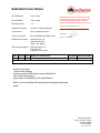
Remarks
Tim,
Submittal #54 has been uploaded to Crush.
Signature
Prolog Manager
Printed on: 7/18/2014
Prolog
Signed Date
Page 2 of 2
SUBMITTAL REVIEW FORM
Stapleton Northfield Campus - SLC
ME Project Number: DV13044.00
Specification Sections:
23 52 00
Submittal Number: 0054-235200-0
Packaged Boiler Product Data
Review Date: 08/14/14
(Received by M-E Engineers, Inc. 08/04/14)
Subcontractor:
RK Mechanical
NOTE:
Checking is only for general conformance with the design concept of the project and general compliance with the
information given in the contract documents. Any action shown is subject to the requirements of the plans and
specifications. Contractor is responsible for: dimensions which shall be confirmed and correlated at the job site;
Fabrication processes and techniques of construction; coordination of his work with that of all other trades and the
satisfactory performance of his work.
If the use of any equipment or item in this submittal requires any deviation from the contract documents, or if there is a
need to provide access or space due to dimensional constraints, the contractor shall provide a shop drawing for review
showing how this item can be accommodated and shall be responsible for any deviations in related work due to its use.
Unless noted otherwise, the contractor is still responsible for performing in accordance with the contract documents.
The following items have been reviewed for conformance with the requirements of the Contract Documents:
DISPOSITION
Item and Review Comments
Note: Items in ( ) Represent Item Tags from Equipment Schedule
N
Boilers
Verify gas pressure and regulator(s) requirements, coordinate with Plumbing Contractor.
Design documents based on 14” WC.
M-E ENGINEERS, INC.
James Stieg, PE, LEED AP
Associate
Disposition Code:
N – No exception taken. Resubmittal not required.
M – Make corrections noted. Resubmittal not required if installation complies with notes.
R – Revise and Resubmit
V – Reviewed Only
S – Submit Specified Item
M
X
R
V
S
Submittal Cover Sheet
Date Submitted:
July 17, 2014
Date Due Back:
July 28, 2014
RK Submittal No.:
3-0
Specification Section:
23 5200 - Condensing Boilers
Project Name:
DPS - Northfield Campus
General Contractor:
GE JOHNSON CONSTRUCTION
Mechanical Contractor:
RK Mechanical, Inc.
3800 Xanthia Street
Denver, CO 80238
Subcontractor/Supplier:
Taft Engineering LLC
P.O. Box 3153
Englewood, CO 80155
Reviewed for general conformance with the
contract requirements and with other crafts.
Approved for submittal to the architects subject to architects and engineers approval.
0054 - 23 52 00 Boilers - FA
G.E. JOHNSON
NSONCONSTRUCTION
CONSTRUC CO.
Signed by:
ITEM
1
COPIES
REV
0
clementst 06/19/2013
18/2013
Date: 07/18/2014
SUBMITTAL DESCRIPTION
Condensing Boilers
DRAWING
MANUFACTURER
Aerco
Vendor to provide:
Touch screen display
Factory mounted 480v power source transformer
Flue outlet temp sensor
Spare parts as identified by the specifications.
Boiler to be compatible with operating on emergency generator
power
3800 Xanthia Street
Denver, Colorado 80238
ph: 303.355.9696
fx: 303.355.8666
www.rkmi.com
19
30
29 21
P
3"øHWR
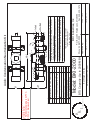
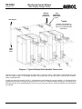
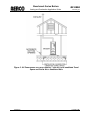
SHOP DRAWING:
BOILERS WILL BE
LOCATED ON
HOUSEKEEPING PAD
AS SHOWN ON M6.01
IN AREA C (ROOM 142)
MECHANICAL.
UH
S1.03
3"øHWS
B
B
S1.02
S1.01
4"øHWR
4"øHWR
4"øHWS
4"øHWS
19
AIR SEPERATOR
HWP
S1.02
GLYCOL FEED
ASSEMBLY
4" THICK
HOUSEKEEPING
PAD BY GC (TYP).
ET
2
HWP
Q
S1.01
Q.
Q
1"øHWS
S1.01
GFP
S1.01
A
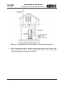
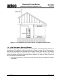
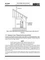
SLC BLDG - ENLARGED MECHANICAL ROOM PLAN
SCALE: 1/4" = 1'-0"
30
W
21
HWS
Condensing Boilers
Vendor to provide:
Touch screen display
Factory mounted 480v power source transformer
Flue outlet temp sensor
Spare parts as identified by the specifications.
Boiler to be compatible with operating on emergency generator power
29
AERCO INTERNATIONAL, INC.
100 Oritani Drive, Blauvelt, NY 10913, Phone 845‐580‐8000
TRANSMITTAL OF SUBMITTAL DRAWINGS
Date: June 26, 2014
Purchaser: RK Mechanical
3800 Xanthia St.
Denver, CO 80238
Attn: Brian Hansen
Project:
Purchase Order #:
AERCO Register #:
Taft Project #:
# of Submittals:
Stapleton Northfield HS ‐ DPS
4091‐P001
TBD
20546
1 ‐ Electronic
The enclosed materials:
X
REQUIRE ENGINEER'S APPROVAL
Your order is being held pending the receipt of your written release and one set of approved drawings. As soon as these are received at Aerco, we will release the order in accordance with the production schedule shown on the cover page of the submittal. This data should be returned to us through your Taft Engineering contact.
ARE FOR RECORD ONLY
Please forward required sets of drawings which are enclosed to your customer, along with letter of transmittal. Retain one for your records.
PLEASE SELECT ONE OPTION BELOW UPON RETURN OF SUBMITTALS
X
Building Supply Gas Pressure is:
Building Supply Gas Pressure is:
Building Supply Gas Pressure is:
≤14.0" WC
>14" WC to 20" WC
Other (Please Specify)
> 1.5psi ‐ 2psi Please Confirm
>20.0" WC ‐ 1.5psi
NOTE: Aerco Gas Regulators are based upon the building supply gas pressure. If no selection is
chosen at time of release, then NO gas regulator will be supplied unless previously stated on the quotation that has been referenced on the customer's purchase order.
AERCO INTERNATIONAL, INC.
100 Oritani Drive, Blauvelt, NY 10913, Phone 845‐580‐8000
TABLE OF CONTENTS
Date:
Project:
Project Location:
Taft Project #:
6/26/2014
Stapleton Northfield HS ‐ DPS
Denver, CO
20546
Engineer:
Engineer's Location:
Purchaser:
Purchase Order #:
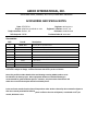
DESCRIPTION
ME Engineers
Denver, CO
RK Mechanical
4091‐P001
DOCUMENT
‐ PURCHASED EQUIPMENT
‐ ACCESSORIES AND SPECIAL NOTES
‐
‐
‐
‐
‐
‐
‐
‐
‐
‐
‐
‐
‐
‐
‐
‐
‐
‐
‐
WARRANTY (SPECIAL)
BENCHMARK TECHNICAL DATA SHEET
BST TECHNICAL DATA SHEET
BMK SERIES
CMORE TECHNICAL DATA SHEET
PROTONODE COMMUNICATION GATEWAY DATA SHEET
BTU VS. VALVE POSTION CHART
WATER SIDE PRESSURE DROP CHART
THERMAL EFFICIENCY CHART
DEMINSIONAL DRAWING
ANCHOR BOLT LOCATION
CLEARNCE DRAWING ZERO SIDE WALL
CMORE CONTROLS ONBOARD BST WIRING DIAGRAM
MOTORIZED VALVE DATA SHEET
GAS REGULATOR
CONDENSATE NEUTRALIZER KIT
FLOW SWITCH DATA SHEET
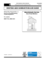
GAS SUPPLY DESIGN GUIDE
VENTING AND COMBUSTION AIR GUIDE
ELECTRICAL POWER GUIDE
AP‐A‐936 REV. A
SD‐A‐896 REV. C
SD‐A‐996 REV. A
SD‐A‐1011 REV. A
SD‐A‐630 REV. B
BKI‐2000
GF‐2030
GF‐2050
GF‐2060
AERCO INTERNATIONAL, INC.
100 Oritani Drive, Blauvelt, NY 10913, Phone 845‐580‐8000
PURCHASED EQUIPMENT
Date:
Project:
Project Location:
Taft Project #:
6/26/2014
Stapleton Northfield HS ‐ DPS
Denver, CO
20546
Engineer:
Engineer's Location:
Purchaser:
Purchase Order #:
ME Engineers
Denver, CO
RK Mechanical
4091‐P001
Purchased Equipment:
Model: BMK1500
Style: GWBR9
Description: Aerco Condensing Boiler, 1500MBH, LowNOx, Natural Gas Firing
Quantity: 2
Including the following:
‐
‐
‐
‐
‐
‐
‐
‐
‐
‐
‐
‐
‐
Control Mode: Boiler Sequencing Technology
Fault Mode Diagnostic Panel with Digital Readout
Electrical Supply Requirements: 120V/1Ph/60HZ (16FLA)
Gas Train is in accordance with CSD-1 and IRI
Normally Open Fault Relay
Adjustable Automatic Reset High Limit
Manual Reset High Limit - 210°F Setpoint
20:1 Modulating Air/Fuel Valve
Electric Probe Low Water Cut-Off
Combination Temperature and Pressure Gauge
Insulated Heat Exchanger
Pressure Relive Valve, set at
75 psi
(shipped loose)
Condensate Trap (shipped loose)
AERCO INTERNATIONAL, INC.
100 Oritani Drive, Blauvelt, NY 10913, Phone 845‐580‐8000
ACCESSORIES AND SPECIAL NOTES
Date:
Project:
Project Location:
Taft Project #:
6/26/2014
Stapleton Northfield HS ‐ DPS
Denver, CO
20546
Engineer:
Engineer's Location:
Purchaser:
Purchase Order #:
ME Engineers
Denver, CO
RK Mechanical
4091‐P001
Accessories:
QTY:
Part #:
2
2
1
1
58088‐W75
124259
64084
62010
2
BKI‐2000
Description:
Accessory Kit for 75psi Relief Valve
Low Pressure Gas Regulator, 1‐1/2" NPT
Protonode Communication Gateway for BACnet
Transformer for Gateway Condensate Neutralizer Kit ‐ Up to 2000MBH
92084‐8
3" Motorized Valve, 24V, w/ Electronic Fail Safe
2
FS251
3" Flow Switch
2
480V to 120V Tranformer
2
BST Header Temperature Sensor
61040
1
Shipping date is 4‐6 weeks following receipt of submittal approval and written release. Lead time is subject to change. Confirm lead‐time with factory at time of release. Note: This portfilio includes detailed data and drawings covering AERCO products to be furnished for the above project. Other equipment shown on Installation drawings is recommended for good installation practice. However, only those items listed above and within the accessories description will be furnished by Aerco.
Prices are firm 4 months from the date of the purchase order. Orders released by the customerfor shipment after the 4 month period will be billed at prices in effect at the time of shipment, orescalated at 1.5% per month, whichever is less.
AERCO INTERNATIONAL, INC.
100 Oritani Drive, Blauvelt, NY 10913, Phone 845‐580‐8000
Equipment Warranty Information
Date:
Project Name:
Project Location:
Taft Project #:
Model #:
Model Style:
6/27/2014
Stapleton Northfield HS ‐ DPS
Denver, CO
20546
BMK1500
GWBR9
Engineer:
Engineer's Location:
Purchaser:
Purchase Order #:
Aerco SO#:
Quantity:
Date of Shipment:
ME Engineers
Wheat Ridge, CO
RK Mechanical
4091‐P001
TBD
2
TBD
Serial Number(s): TBD
Warranty Description ‐ Job Specific
Pressure Vessel/Heat Exchanger: 215 Year from date of Shipment * 5 Years Extended Warranty Purchased. *
Years from Date of Shipment
Boiler/Water Heater Controls: 2 Years from Date of Shipment *Standard*
Parts/Other Components: 2 Years from Date of Shipment * 6 Months Extended Warranty Purchased *
** See Attached Document for Standard Warranty Information **
Product Support Contact Information
Taft Engineering Inc.
Cory Hesterwerth
Product Support Manager
9800 E. Easter Ave.
Suite 130
Centennial, CO 80112
(P) 303‐753‐4584
(T) 720‐941‐1199
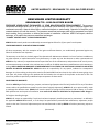
LIMITED WARRANTY: BENCHMARK 750 - 6000 GAS-FIRED BOILER
BENCHMARK LIMITED WARRANTY
BENCHMARK 750 - 6000 GAS-FIRED BOILER
PRESSURE VESSEL/HEAT EXCHANGER: 10 YEAR NON-PRORATED FROM SHIPMENT The pressure
vessel/heat exchanger shall carry a 10 year non-prorated, limited warranty from date of shipment against any
condensate corrosion, thermal stress failure, mechanical defects or workmanship. Operation of the boiler using
contaminated air will void the warranty. The pressure vessel/heat exchanger shall not be warranted from failure
due to scaling, liming, corrosion, or erosion due to water or installation conditions. AERCO will repair, rebuild or
exchange, at its option the pressure vessel/heat exchanger.
“C-MORE” CONTROL PANEL: 2 YEARS FROM SHIPMENT
AERCO labeled control panels are conditionally warranted against failure for (2) two years from shipment.
OTHER COMPONENTS: 18 MONTHS FROM SHIPMENT
All other components, with the exception of the igniter and flame detector, are conditionally guaranteed against any
failure for 18 months from shipment.
The warranty as set forth on the back page of the Operations & Maintenance Manual is in lieu of and not in addition to
any other express or implied warranties in any documents, or under any law. No salesman or other representative of
AERCO has any authority to expand warranties beyond the face of the said warranty and purchaser shall not rely on any
oral statement except as stated in the said warranty. An Officer of AERCO must do any modifications to this warranty in
writing. AERCO MAKES NO WARRANTY OF MERCHANTABILITY OR FITNESS FOR PARTICULAR PURPOSE OR ANY OTHER
EXPRESS OR IMPLIED WARRANTIES. AERCO disclaims all responsibility for any special, incidental or consequential
damages. Any claim relating to the product must be filed with AERCO not later than 14 days after the event-giving rise to
such claim. Any claims relating to this product shall be limited to the sale price of the product at the time of sale. The
sale of the product is specifically conditioned upon acceptance of these terms.
CONDITIONS OF WARRANTY:
Should an AERCO gas-fired (natural gas, propane, and natural gas/propane dual fuel only) boiler fail for any of the above
reasons within the specified time period from the date of original shipment(s), AERCO shall at its option modify, repair
or exchange the defective item. AERCO shall have the option of having the item returned, FOB its factory, or to make
field replacements at the point of installation. In no event shall AERCO be held liable for replacement labor charges or
for freight or handling charges.
AERCO shall accept no responsibility if such item has been improperly installed, operated, or maintained – as defined in
the applicable AERCO O&M manual, or if the buyer has permitted any unauthorized modification, adjustment, and/or
repairs to the item. The use of replacement parts not manufactured or sold by AERCO will void any warranty, express or
limited.
(Continued)
AERCO International, Inc.
100 Oritani Dr., Bradley Corporate Park, Blauvelt, NY
Telephone: 845-580-8000
www.aerco.com
Rev. 11/22/13
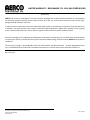
LIMITED WARRANTY: BENCHMARK 750 - 6000 GAS-FIRED BOILER
(Continued)
AERCO shall accept no responsibility if such item has been damaged due to contaminated combustion air containing but
not limited to sheetrock particles, plaster board particles, dirt, dust, lint, and corrosive chemicals such as chlorine gas,
halogenated hydrocarbons, and Freon.
In order to process a warranty claim a formal purchase order number is required prior to shipment of any warranty item.
In addition, the returned item must include a Returned Goods Authorization (RGA) label, attached to the shipping
carton, which identifies the item's return address, register number and factory authorized RGA number.
Warranty coverage for all components and equipment mentioned in said warranty are not valid unless the water heater
is started up by a factory certified SST (Service, Start-Up and Troubleshooting) Technician and an AERCO start-up sheet is
completed.
This warranty coverage is only applicable within the United States, Canada and Mexico. All other geographical areas
carry a standard warranty of 18 months from date of shipment or 12 months from startup, whichever comes first.
Rev. 11/22/13
AERCO International, Inc.
100 Oritani Dr., Bradley Corporate Park, Blauvelt, NY
Telephone: 845-580-8000
www.aerco.com
Rev. 11/22/13
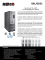
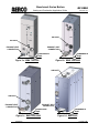
BMK SERIES
TECHNICAL DATA SHEET
Benchmark 750 - 6000
Condensing Hydronic Boilers
The AERCO Benchmark (BMK) Water Boiler is designed for condensing
application in any closed loop hydronic system. It delivers unmatched
burner modulation to match energy input directly to fluctuating system
loads to yield the highest possible seasonal efficiencies. And no other
product packs as much capacity into such a small footprint.
To minimize emissions, the BMK Series is fitted with a low NOx
burner whose emissions will meet the most stringent NOx and CO
requirements. The fully modulating burner also maintains AERCO
standards for energy efficiency, longevity, reliability and construction
quality.
The BMK Series comes standard with AERCO’s Patent Pending,
Oxygen Level (O2) monitoring system. This monitoring system,
designed to display the O2 level directly on the unit in real time, can
also be remotely monitored via Modbus giving the customer the ability
to measure the emissions level and fuel economy of the boiler without
traditional combustion calibration devices.
The BMK boilers can be used as an individual unit or in modular
arrangements and offers selectable modes of operation. In addition to
controlling the boiler according to a constant set point, indoor/outdoor
reset schedule or 4-20mA signal, one or more units can be integrated
via Modbus communications protocol. For boiler plants ranging
from 2-8 boilers, AERCO’S built-in Boiler Management Sequencer*
can be utilized. For heating plants greater than 8 boilers, AERCO’s
ACS (AERCO Control System) provides the right solution. Likewise,
Benchmark systems can be easily integrated with a facility-wide
Energy Management or Building Automation System.
*AERCO’s on-board BMS sequencer available December 2013
FEATURES:
•
•
•
•
•
•
•
•
•
Natural Gas, Propane, or Dual Fuel (model dependant)
20:1 Turndown Ratio (5%) depending on capacity
Oxygen Level (O2) Monitoring Standard
Stainless Steel Fire Tube heat exchanger
Capable of variable primary flow Installations
NOx Emissions capable of 9PPM or less @ all firing
rates *depending on capacity
Compact Footprint
Precise Temperature Control
On Board Boiler Management Sequencer (BMS)
•
•
•
•
•
Ducted Combustion Air Capable
Easy Open Access for Service
Acceptable vent materials AL29-4C, Polypropylene,
PVC, cPVC (model dependant)
Reliable Quiet Operation
Controls Options
• Constant Setpoint
• Indoor/ Outdoor Reset
• Remote Setpoint
•
4-20mA signal or ModBus
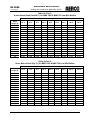
RATINGS:
Model Number
Min Input
MBH
Max Input
MBH
Max Outputa
MBH
Efficiency
Range
AHRI
Efficiency 80º
to 180ºF
BMK 750
50
750
653-720
87%-98%
95.50%
BMK 1000
50
1000
870-960
87%-98%
96.80%
BMK 1500
75
1500
1305-1425
87%-99%
95% (pending)
BMK 2000
100
2000
1740-1900
87%-98%
95% (pending)
BMK 2500
167
2500
2175-2360
87%-98%
93.50%
BMK 3000
200
3000
2610-2880
87%-98%
93.50%
BMK 6000**
400
6000
5220-5670
87%-98%
94.50%
Max output dependent upon application - See efficiency curves
**See separate BMK6000 Technical Data Sheet for additional BMK6000 details
a
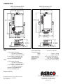
DIMENSIONS (INCHES):
Model
(Width) A
(Depth) B
(Height) C
D
E
F
G
H
I
J
K
L
BMK 750
28’’
25’’
78’’
34’’
10’’
10’’
53’’
21’’
17’’
4’’
5’’
51.8’’
BMK 1000
28’’
25’’
78’’
34’’
10’’
10’’
53’’
21’’
17’’
4’’
5’’
51.8’’
BMK 1500
28’’
43.6’’
78’’
58.4’’
7’’
11.5’’
57.8’’
18’’
22’’
8.9’’
4.7’’
19.5’’
BMK 2000
28’’
43.6’’
78’’
58.4’’
7’’
11.5’’
57.8’’
18’’
22’’
8.9’’
4.7’’
19.5’’
BMK 2500
28’’
56’’
78’’
68.4’’
5.4’’
11.5’’
57.8’’
18’’
22’’
6.4’’
3.6’’
26’’
BMK 3000
28’’
56’’
78’’
68.4’’
5.4’’
11.5’’
57.8’’
18’’
22’’
6.4’’
3.6’’
26’’
BMK 6000**
34’’
89.3’’
79.4’’
108.3’’
6.2’’
42.1’’
N/A
15.6’’
N/A
10’’
28.7’’
23.7’’
**See separate BMK6000 Technical Data Sheet for additional BMK6000 dimension details
***BMK750/1000 Feature Dual Inlet Connections
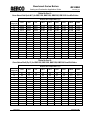
SPECIFICATIONS:
BMK750
BMK1000
BMK1500
BMK2000
BMK2500
BMK3000
BMK 6000**
ASME
Sect.IV
ASME
Sect.IV
ASME
Sect.IV
ASME
Sect.IV
ASME
Sect.IV
ASME
Sect.IV
ASME
Sect.IV
Gas Connections
(NPT)
1’’
1’’
1.5’’
2’’
1.5’’
2’’
2’’
Max. Gas Pressure
14’’
14’’
14’’
14’’
14’’
14’’
2psi
Min. Gas Pressure
4’’
4’’
4’’
4’’
4’’
4’’
14’’
Max. Allowed
Working Pressure
160 PSIG
160 PSIG
160 PSIG
160 PSIG
160 PSIG
160 PSIG
80 PSIG/150
PSIG Optional
Electrical Req.
120V/1PH/60Hz 1
13 FLA
13 FLA
16 FLA
16 FLA
N/A
N/A
N/A
Electrical Req.
208V/3PH/60Hz 1
N/A
N/A
N/A
N/A
10 FLA
10 FLA
19 FLA
Electrical Req.
460V/3PH/60Hz 1
N/A
N/A
N/A
N/A
5 FLA
5 FLA
12 FLA
Water Connections
(Flanged)
3’’
3’’
4’’
4’’
4’’
4’’
6’’
Min. Water Flow (GPM)
25
25
25
25
35
35
75
Max. Water Flow (GPM)
175
175
250
350
350
350
600
16.25
14.25
34
28
58
55
110
Water Pressure Drop
3.0 PSIG
@
100 GPM
3.0 PSIG
@
100 GPM
3.0 PSIG
@
170 GPM
3.0 PSIG
@
170 GPM
3.0 PSIG
@
218 GPM
3.0 PSIG
@
261 GPM
4.0 PSIG
@
570 GPM
Turndown
15:1 (7%)
20:1 (5%)
20:1 (5%)
20:1 (5%)
15:1 (7%)
15:1 (7%)
15:1 (7%)
6 Inch
6 Inch
6 Inch
8 Inch
8 Inch
8 Inch
14 Inch
AL29-4C
Polypro,
CPVC, PVC
AL29-4C
Polypro,
CPVC, PVC
AL29-4C
Polypro
AL29-4C
Polypro
AL29-4
Polypro
AL29-4C
Polypro
AL29-4C
Natural Gas,
Propane
Natural Gas,
Propane
Natural Gas,
Propane, Dual
Fuel
Natural Gas,
Propane, Dual
Fuel
Natural Gas,
Propane, Dual
Fuel
Natural Gas,
Propane, Dual
Fuel
Natural Gas,
Propane, Dual
Fuel
Boiler Category
Water Volume
Gallons
Vent/Air Intake
Connections
Vent Materials
Type of Gas
Temperature
Control Range
50ºF to 190ºF
Ambient
Temperature Range
0ºF to 130ºF
Standard Listings &
Approvals
UL, CUL, CSD-1, ASME, AHRI
Gas Train
Operations
FM Compliant or Factory Installed DBB (IRI) (BMK750-BMK3000 Only) FM Compliant (BMK 6000)
Weight (dry) Ibs.
669
700
1406
1500
2,000
2,170
3,000
Weight (wet) Ibs.
802
817
1654
1760
2,332
2,580
3,920
Shipping Weight Ibs.
862
900
1606
1700
2,200
2,370
3,800
**See separate BMK6000 Technical Data Sheet for additional BMK6000 details
1
See Benchmark Electrical Power Guide GF-2060 for Service Disconnect Switch amperage requirements.
NOTES:
Represented By:
Specifications subject to change without prior notice. Consult website or contact AERCO.
BMK SERIES 08/2013 NY
WATER HEATERS • BOILERS • PARTS & ACCESSORIES
AERCO INTERNATIONAL, INC.
100 ORITANI DR. • BLAUVELT, NY 10913 (845) 580-8000 • FAX (845) 580-8090
www.aerco.com
BST
TECHNICAL DATA SHEET
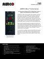
C-MORE CONTROLLER WITH
BOILER SEQUENCING TECHNOLOGY (BST)
Master On
On
On
Off
Off
Off
LOAD SHARING STRATEGY MAXIMIZES ENERGY EFFICIENCY
It requires less energy for a group of modulating boilers, each firing at “part load,” to heat a building, than
for a single boiler operating at “full fire” to carry the entire workload. To meet building demand, the BST will
employ as many boilers as available, each operating at its most efficient firing rate. Importantly, because the BST
reacts in real-time to, up to 8 boilers, changes in the number of boilers available, users can take a unit offline
for maintenance at any time or bring on back-up boilers for extremely cold conditions without changes to the
BST. And as individual boilers are added or deleted, the energy delivered is automatically adjusted to prevent
fluctuations in the header temperature of the plant.
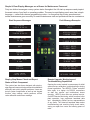
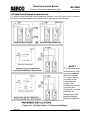
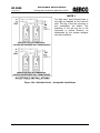
Typical Staging Example Demonstrates “Part Load” Efficiency
The first boiler unit comes
online and will gradually
increase its air-fuel valve
position to meet demand.
When it reaches 50% – a
second unit is called into
service.
The two boilers will split the
load – each firing at 30%
air-fuel valve position to meet
demand. If additional heat is
required, a third unit is called
into service.
Three boilers, each firing at
30% air-fuel valve position,
satisfies the demand more
efficiently than either two units
at 50% or one unit at 100%.
This same principle applies to
much larger plants.
FEATURES:
•
•
•
•
•
•
•
•
Increase System Turndown to Maximize Operating
Efficiency
Control Up to 8 Boilers via Modbus Interface
Automatic Load Matching Precisely Meets Demand
Changes
“Bumpless” Energy Transfer
Multiple Configuration Options
User-Friendly Software Makes Programming Easy
Full System Information VFD Display on Master Unit
Controls external 24V AC/DC motorized isolation valve
•
•
•
•
•
Easy Integration to BAS or EMS via Modbus Open
Protocol
Single Point BAS or EMS Data Gathering for up
to 20 BAS System Operating Parameters and 18
Operating Parameters of Each Boiler
Available Standard on all AERCO Benchmark
Boilers. No Additional panel necessary.
Can incorporate different unit capacities for
optimized efficiency.
Utilizes a Header Senor directly connected to the
BST Master Unit, or an optional Modbus Header
Sensor.
STATE-OF-THE-ART CONTROL SYSTEM SUPPORTS EFFICIENT BOILER PLANT OPERATION!
The C-MORE AERCO with Boiler Sequencing is a flexible controller designed to maximize energy savings in
modular boiler plants. The BST can stage and coordinate the operations of up to 8 boilers and is uniquely designed
to maximize uptime reliability and the operating efficiency of condensing equipment capable of unmatched
modulation. For boiler plants greater than 8 boilers, the AERCO Control System (ACS) panel is required.
Able to regulate overall plant output with precise accuracy, a boiler plant with ±4°F header temperature variation is
assured under normal load conditions. It offers sequential or parallel operation flexibility, and user programmable
modes of operation that can be changed in the field. The C-MORE automatically rotates the lead unit to help
equalize boiler runtime or number of cycles.
FULLY COMPATIBLE WITH BAS OR EMS SYSTEMS VIA MODBUS OPEN PROTOCOL
For facilities that have taken a building-wide approach to energy efficiency, the C-MORE supports easy integration
with Building Automation Software (BAS) or Energy Management Software (EMS) programs via Modbus protocol
and RS-485 interface. A standards-based open protocol used throughout the buildings controls market, Modbus
integration will enable facility managers to monitor all operations from any building control platform. BAS or
EMS can poll 20 System Operating Parameters, and 18 unit Operating Parameters per Boiler through a single
connection, including: (for greater detail consult AERCO Modbus Communications Manual GF-114).
BST System Parameters
•
•
•
•
•
•
•
•
•
•
Cmore BST mode
BST setpoint
BST setback setpoint
BST setback start
BST setback end
BST auto master
BST Unit outlet temp
BST num units enabled
BST units faulted
Master Unit Address
•
•
•
•
•
•
•
•
•
•
BST header temp
BST outdoor temp
BST fire rate output
BST Unit Ignited
BST Active Setpoint
Next turn on fire rate
BST sp high limit
BST sp low limit
BST temp high limit
BST setpoint mode
Boiler Parameters
•
•
•
•
•
•
•
•
•
Comm addr
Unit Status
Fault status
Outlet temp
Ffwd temp
Inlet temp
Exhaust temp
Air temp
Flame strength
Configuration Options
Indoor/Outdoor Reset
A change in the outside air condition results in a Process
Application proportionate change in header temperature – a
function of the adjustable reset ratio (0.3 – 3.0).
Constant Setpoint
Delivers fixed supply water temperature at set points of 50°F220°F (dependent upon boiler maximum temperature limit).
4-20mA Signal
Header temperature responds linearly to an external 4-20mA
control signal.
Network Communications
Enables EMS or BAS system to drive boiler plant setting for
header set point temperature via Modbus connection to BST.
Also provides communication link between the boiler and the BST
to allow direct communication. This enables the EMS/BAS to
query and capture faults of BST and 20 BST System operating
parameters as well as 18 operating parameters of each individual
boiler.
•
•
•
•
•
•
•
•
•
Fire rate in
Fire rate out
Unit type
Unit size
Boiler Isolation Valve State
Network remote setpoint
Run cycles
Run hours
O2 Level
Typical Applications
Indoor/Outdoor Reset Hydronic Heating
Process Application
Water Source Heat Pump
Domestic Water Generation
Supplemental Heat Recovery Equipment
Swimming Pool Heating
Computer Controlled Building Management
Industrial Process
Greenhouse Application
Computer Controlled Building Management
EMS Data Logging & Trend Analysis
NOTE: Supply Header Temperature Sensor Is Sold Separately (See OnBoard BST O&M)
ROBUST FEATURES SIMPLIFY CONTROL
•
Application Flexibility – Different configuration options
meet the needs of any closed loop system and can be
changed in the field.
•
Time Delay Between Boiler Start – An adjustable
time delay between boiler starts allows for a smooth
energy input without spikes in electrical, gas or venting
conditions.
•
Automatic Allowance for Maintenance – By
continuously monitoring the number of boilers available
for operation, the system will automatically operate the
next boiler needed to meet demand if a unit malfunctions
or is taken off-line for maintenance.
•
Adjustable Off Set – The BST includes a 7-day
programmable clock to support night setback and/or
daily setback periods. The BST will shift from the original
set point to a higher or lower temperature.
•
Two Interlock Circuits – Monitor pumps, combustion
air dampers, or other equipment using two interlock
circuits that must be completed before plant operations
begin.
•
•
•
Accuracy – The BST uses PID (Proportional & Integral +
Derivative) and Dynamic Up/Dynamic Down Modulation
control algorithm to provide a dynamic response to all
changes in plant operation. Header temperatures, as
well as percentage boiler input, are precisely controlled
with virtually no overshoot or short cycling of equipment.
A header temperature of ±4°F is assured during
continual plant operation.
•
“Bumpless” Energy Transfer – When staging boilers
sequentially, the BST can bring additional units online at
an adjustable percentage of input selected by the user.
•
Lead and Lag Boiler Designation – The BST will
select the Lead and Lag boilers by either Unit Size or
Run Hours depending on user setting. The Lead and
Lag boilers can also be manually selected by the user.
•
Lead Boiler Time Rotation – Rotates the operating
lead boiler at specified time and helps equalize runtime.
•
Anti-Cycling Features – These features prolong the
system’s stay at specific state (firing/off) - reducing
the number of cycles while maintaining accurate
temperature control.
Power Off Memory – By using non-volatile memory,
programs are retained through a shut down of more
than two years. No batteries required.
Simple Installation – The C-MORE control system
operates on boiler unit’s standard power supply.Twisted
pair, shielded wire connections between the Master
boiler unit and slave individual boilers is required
to support communications. An RS-485 interface is
required to link an EMS. RS-485 communications wiring
supports a distance of up to 4,000 feet between BAS
and boilers.
•
Flexible & Expandable – The BST can support up to
8 AERCO boilers – which can be fully integrated with
any EMS or BAS software via the Modbus protocol.
AERCO also offers Gateway product for LON, BACnet
(additional gateway product required) and Johnson
Controls N2.
•
Building Reference Temperature Inputs – Boilers can
be clamped at minimum and maximum temperatures,
and the building reference temperature adjusted to drive
plant header temperature. This allows a wide range of
boiler responses to outside air changes for maximum
comfort.
•
•
•
•
Shutoff Delay Temp
Deadband high
One Boiler Mode
•
•
Demand offset
Deadband low
One Boiler Mode – is an INNOVATIVE and
EXCLUSIVE feature in the AERCO BST control that
detects a “low-flow” condition in a multi-boiler system.
When the AERCO BST determines that a low-flow
condition exists, it will slowly shut down one boiler
at a time in an attempt to raise the Fire Rate of the
remaining boilers. If the low-flow condition persists
and only a single boiler remains ignited, the AERCO
BST will use the “Outlet Temperature Sensor” of the
remaining ignited boiler to control the temperature. The
Outlet Temperature Sensor is mounted in the individual
boiler and drastically increases the response time
to precisely control temperature. The distant header
sensor is ignored in this mode of operation.
•
Setback Setpoint Gradual Decrease – Whenever
boilers are running at a high rate and the SetbackSetpoint feature is activated, the sudden decrease in
setpoint will cause the PID to drastically cut back on
fire rate. This sudden decrease in fire rate will often
cause the boilers to drop below their Stop Levels
causing them to turn off, thereby causing excessive
cycling and loss of heating capacity while the boilers
can re-ignite. The Setback-Setpoint gradual
decrease feature will decrease the setpoint, lowered
by the activation of the Setback-Setpoint feature, at
a slow rate thereby allowing the PID to recover and
prevent any boilers from shutting down if not required
to do so.
•
Warm-Up and Low-Fire-Delay Fire Rate Hold –
When an extra boiler is ignited to meet demand, the
fire rate of all ignited boilers will be held at their present
level until the newly ignited boiler has completed
Warm-up and Low Fire Delay. When the newly ignited
boiler has completed Warm-up and Low Fire Delay,
all boiler fire rates will decrease to approx 30% Fire
Rate. All boiler fire rates will then rise together to the
required fire rate to meet demand.
•
Next Turn On Valve Position – When all ignited
boilers reach or exceed the BST Next on VP value,
another boiler will be ignited to share the load (if one
is available). The default value is 50%.This feature is
also useful if a user wishes to always have as few
boilers on at any one time. Setting the BST Next on
VP value to a high number (Example 100%) will only
ignite a new boiler if all currently ignited boilers reach
their total BTU capacity (100%).
•
Warm-Up and Low-Fire-Delay PID Hold – Whenever any boiler is in either Warm-up or Low
Fire Delay, the Integral portion of the BST PID will
be frozen in order to prevent the PID from winding
up too high causing the temperature to overshoot
causing an over-temp condition.
•
Setpoint Approach Rate control – To avoid header
temperature overshoots, whenever the header
temperature nears the setpoint temperature at a rate
too quickly to prevent a temperature overshoot, the
BST fire rate will temporarily decrease in order to
lower the temperature rise momentum. This feature
will help avoid temperature overshoots due to
variable flow as well as other conditions.
SPECIFICATIONS:
Standard Listings & Approvals ............................... ........UL, CUL
NOTES:
Represented By:
Specifications subject to change without prior notice.
Consult website or contact AERCO.
BST 2/2014 NY
WATER HEATERS • BOILERS • PARTS & ACCESSORIES
AERCO INTERNATIONAL, INC.
100 ORITANI DR. • BLAUVELT, NY 10913 (845) 580-8000 • FAX (845) 580-8090
www.aerco.com
CMR
TECHNICAL DATA SHEET
AERCO C-More™ Control System
Advanced Technology for Easy and Reliable Control of
AERCO Gas-Fired Boilers and Water Heaters.
The AERCO C-More Control System offers customers more than
just an easy-to-use, highly reliable control system for boiler and
water heater management. The system incorporates the latest
electronic technology to see and do more than was previously
possible. It reports on individual system components such as unit
status, firing rate and temperature control settings. It provides stepby-step diagnostic menus using clear and simple language and
automatically captures performance history and operating trends.
Beyond these immediate benefits, the ruggedly built system has
been designed using flash-upgradeable software components and
open interoperability standards to support building automation and
energy management software systems. Integrated Boiler and Water
Heater Sequencing Technology is offered standard for optimal
system efficiency and reliability.
It is included as a standard component on all AERCO Benchmark
Boilers and Innovation Water Heaters. Older installations of the
Benchmark boilers and discontinued KC1000 boilers and water
heaters can be easily retrofitted with the AERCO C-More control
system.
AERCO C-More Controller for
Benchmark Boilers and
Innovation Water Heaters
FEATURES:
•
•
•
•
•
Supports BAS and EMS Integration via ModBus
Open Protocol
Integrated Boiler Sequencing Technology (BST) on
Benchmark Units
Water Heater Management (WHM) on Innovation
Units
Optional Gateway for BACnet, Lonworks and N2
Communication Also Available
Common Platform on all Benchmark and Innovation
Units
•
•
•
•
•
•
•
Log Reports and Fault History
Rugged Hardware Design
Simple and Clear Display Messages
Step-by-Step Diagnostic Menus and System
Status Reports
Remote Monitoring Capability
Precise Temperature Control
UL Recognized
Future-Proof Software in a Hardware Enclosure that is Built to Last
The most important feature of any product manufactured in today’s “information age” is its ability to network with
related equipment. And not just the equipment and systems that are available today – but those that are still on
the horizon. This indisputable fact was a guiding principle in the design of the AERCO C-More Control System.
It pairs software flexibility with hardware durability to ensure that your AERCO equipment will be as current
tomorrow as it is today.
Integrated Sequencing Technology
The C-More’s integrated Boiler Sequencing
Technology (BST) for Benchmark boilers & Water
Heater Management (WHM) for Innovation Water
Heaters is designed to maximize energy savings and
uptime reliability in modular unit plants. The BST/
WHM system can stage and coordinate operations
for up to 8 units, utilizing AERCO’s condensing
equipment’s unmatched modulation for utmost
plant efficiency. The system offers sequential and
parallel operation flexibility, and user programmable
operation modes that can be easily adjusted. Furthermore, the system automatically rotates the
lead unit to help equalize runtime or number of
cycles. Master On
On
On
Off
Off
Off
Open Platform Integrates with Energy
Management Systems
The C-More controller is fully compatible with
building-wide energy management systems and
building automation software via ModBus open
protocol. An optional Aerco Communications
Gateway, to support integration with BACnet,
Lonworks and N2 systems, is also available.
Flash-Upgradeable Software
Once an AERCO C-More control module is in
place, all new versions of the system’s operating
software can be uploaded electronically
(or “flashed in”). The ability to upgrade the
controller – without replacing hardware, circuit
cards or boiler equipment – makes it faster,
easier and less expensive to take advantage
of new features and management controls that
become available in the future.
One Controller Fits All
Extensive Log Reports
The system continuously monitors and automatically
captures data associated with operational events,
faults and sensor readings which can be viewed in
real-time via the Modbus RS485 RTU interface or
downloaded for historical analysis through the RS232 interface. Events such as power-up, ignition, and
turn-off are time stamped and sensor value readings
can be logged at flexible intervals established by the
user. The system also maintains a log of the date,
time and details of the last ten system faults to help
end-users recognize boiler shutdown patterns. AERCO C-More internal components are identical
for Benchmark and Innovation equipment. Whole
units or components can be swapped between any
of AERCO’s gas-fired boilers and water heaters as
needed.
Easy Retrofits
An affordable retrofit kit is available to equip any
older existing AERCO gas-fired boiler or water
heater installation with a state-of-the-art AERCO
C-More control system. See document GF-2200 for
Retrofit Kit / Part Number Guidelines to determine
the kit needed for your AERCO equipment.
Simple & Clear Display Messages are a Breeze for Maintenance Personnel
Forty-two distinct messages convey system status throughout the full start-up sequence and pinpoint
the exact nature of any fault or operating problem. The easy-to-read display panel uses clear, simple
language — rather than obscure programming codes – to ensure that day-to-day operations and
annual maintenance goes smoothly for onsite maintenance staff and professional service contractors.
Start Sequence Messages
Fault Message Examples
DISABLED
3:05PM 9/24/12
LOW WATER
LEVEL
STANDBY
3:06PM 9/24/12
AIRFLOW FAULT
DURING PURGE
DEMAND DELAY
30 sec
LOSS OF POWER
3:09PM 9/24/12
WAIT
DIRECT DRIVE
SIGNAL FAULT
PURGING
30 sec
REMOTE SETPT
SIGNAL FAULT
IGNITION TRIAL
4 sec
OUTDOOR TEMP
SENSOR FAULT
WARMUP
120 sec
LINE VOLTAGE OUT
OUT OF PHASE
FLAME PROVEN
3:08PM 9/24/12
NETWORK COMM FAULT
Step-by-Step Menus Check and Report
Status of Each Component
Remote Upgrade, Monitoring and
Troubleshooting Capabilities
The system has also been designed with step-bystep diagnostic menus to help personnel troubleshoot
efficiently and quickly pinpoint problems. Users can
test all system components as well as test keypad
function, relay settings, switch positions, air/fuel
valve calibration and sensor readings.
Opening the control module is unnecessary for initial
system set-up, calibration, troubleshooting or during
normal operations. The AERCO C-More controller
links easily to a laptop via RS-232 connections
so staff can monitor and troubleshoot issues
remotely. AERCO also offers an optional service,
On-AER Remote Monitoring, which monitors boiler
plant operation, logs equipment heartbeat data
and immediately notifies service representatives
of any faults. The historical heartbeat data makes
troubleshooting and resolving faults much easier,
saving on repair time costs and offering peace of
mind. Precise Temperature Control
The superior performance of AERCO equipment is due, in part, to tremendous condensing capabilities and
unique firing technology. Put simply, AERCO extracts and transfers as much heat as possible from a highly
efficient combustion process. Unparalleled, fully modulating, non-stepped burner turndown precisely matches
heat input to load requirements. A state-of-the-art PID control system was employed to fully exploit the potential
of such robust boiler mechanics. In short, it utilizes a Proportional + Integral + Derivative control algorithm to
dynamically respond to changes throughout the heating plant operation. System temperatures, as well as a
percentage of module input can be controlled with virtually no overshoot, droop or short cycling of equipment. A
header temperature of +/– 4°F is assured during continual plant operation.
Integrated Approach to Overall Heating Plant Infrastructure
Such precise temperature control would not be possible without a highly integrated approach to the overall
heating plant infrastructure. The AERCO C-More control supports equipment and information systems which
extend beyond the limits of conventional boiler controls. These features will help you maximize the value of a
sophisticated energy management system, or can assist with basic heating plant management in the absence
of smart building systems.
Interoperability with Energy Management Systems
(EMS) is achieved via the controller’s RS485 port. Customers
who are not equipped to take advantage of these network
technologies can monitor trends in set point, outlet temperature
or firing rates using conventional 4-20 mA signals.
A PID Temperature Control Override function prevents
unnecessary shutdowns caused by external energy management
controls. The feature gradually lowers the firing rate to safely
operate the boiler until conditions return to normal. This prevents
on/off cycling to save energy and reduce equipment wear and
tear.
To help users start the heating plant as temperatures drop –
or begin to promote client comfort and energy savings as
temperatures warm – System Start Temp and Indoor/ Outdoor
Reset controls can be used to enable or disable the boiler based
on outside air temperature.
Similarly, Fail Safe Mode lets users choose to shut down the
system or switch to constant set point operation if external signal
input is ever lost. By choosing to revert to a constant set point,
users can ensure that basic heat and hot water is available to
avoid unnecessary building closures and prevent pipe freezes in
the event of an EMS problem.
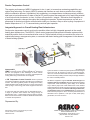
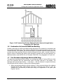
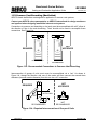
All AERCO equipment supports Variable Flow Designs and
extremely low Flow Conditions without supplemental pumping
requirements. While streamlining plant design is an effective
way to reduce project and overall maintenance costs, AERCO
C-More features are robust enough to support the most complex
heating plant infrastructures. Remote and Delayed Interlocks,
a Pump Delay Timer and/or Aux Start Delay can postpone the
boiler’s start-up sequence until a necessary external device is
activated. Prior to operation, it can open a valve, boiler pump,
gas booster, or louver as shown.
Represented By:
Specifications subject to change without prior notice.
Consult website or contact AERCO.
CMR 03/2014 NY
WATER HEATERS • BOILERS • PARTS & ACCESSORIES
AERCO INTERNATIONAL, INC.
100 ORITANI DR. • BLAUVELT, NY 10913 (845) 580-8000 • FAX (845) 580-8090
www.aerco.com
PROTONODE GATEWAYS
TECHNICAL DATA SHEET
AERCO/PROTONODE GATEWAYS
AERCO offers a multi-protocol, communications gateway to support integration with customers’ building
control and energy management systems. The plug-n-play package supports integration with BACnet/IP,
BACnet MS/TP, LonWorks, and Johnson Controls Metasys N2 systems. AERCO’s Communications Gateway is
available for all AERCO boilers, *water heaters and electronically controlled indirect systems. The gateway may
be installed using the mounting tabs or with the included DIN mount adapter directly into the site’s communications
control panel. Configurations for all AERCO devices are preloaded on both gateways so the installer simply selects
the protocol and configuration via the DIP switches. BACnet gateways are BTL Marked and the LonWorks gateway is
LonMark compliant simplifying the commissioning process. Both gateways are programmed to communicate up to:
•
•
•
•
Twelve (12) C-More controlled boilers or water heaters
Four (4) AERCO Modulex boilers
Six (6) SmartPlates or electronically controlled indirect water heaters
Two (2) BMS II, one dedicated to control the C-More and another to control the Modulex systems
A list of standard control points for each category of equipment includes set point, fire rate, outlet temperature,
unit status, run cycles and run hours.
*Helitherm, U-Tube style, and SmartPlate water heaters must be equipped with the company’s Electronic Control System.
FEATURES:
•
•
•
Built-in translation for BACnet/IP, BACnet MS/
TP, LonWorks, Metasys N2 and Modbus TCP
Protocols
Select protocol and baud rate in the field using
simple DIP switch selection
Captures alarm and trend history for faster
troubleshooting
•
•
Non-volatile memory retains point mappings and
programs in the event of power loss.
Approvals: BACnet Testing Labs (BTL) B-ASC on
ProtoNode RER, CE Mark, LonMark 3.4 Certified
on ProtoNode LER, TUV approved to UL 916
DIMENSIONS:
AERCO/ProtoNode-RER-E
AERCO/ProtoNode-LER
(Serial Ethernet, P/N 64084)
(LonWorks, P/N 64085)
SPECIFICATIONS:
64084:
1 - 6 pin Phoenix Connector
• 1 RS-485 +/- Ground port
• Power +/- Frame Ground port
1 - 3 pin Phoenix connector RS-485
• 1 RS-485 +/- Ground port
1 Ethernet -10/100 Ethernet port
64085:
Power Requirements……………… 9-30 VDC or 9-24 VAC
Current draw @ 12V
64084…………………………… @ 12V = 150 mA
64085…………………………… @ 12V = 279 mA
Operating Temp.……………… -40oF to 187oF (-40oC to 85oC)
Relative Humidity ………………… 5-90% RH, non-condensing
Dimensions………………………… 4.52 x 3.25 x 1.60 inches
Warranty ……………………… Two (2) years return to factory
1 - 6 pin Phoenix Connector
• 1 RS-485 +/- Ground port
• Power +/- Frame Ground port
1 - 3 pin Phoenix connector RS-485
• 1 RS-485 +/- Ground port
1 Ethernet -10/100 Ethernet port
1 FTT-10 LONWORKS port
Represented By:
Specifications subject to change without prior notice.
Consult website or contact AERCO.
CG-1 11/2011 NY
WATER HEATERS • BOILERS • PARTS & ACCESSORIES
AERCO INTERNATIONAL, INC.
100 ORITANI DR. • BLAUVELT, NY 10913
(845) 580-8000 • FAX (845) 580-8090
www.aerco.com
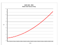
BMK 1500
BTU vs. Valve Position
1600
1500
1400
1300
1200
MBH
1100
1000
900
800
700
600
500
400
300
200
100
0
16
20
30
40
50
60
70
80
90
100
BMK 1500 ‐ 2000
Water Side Pressure Drop 6.5
6
5.5
5
4.5
psi
4
3.5
3
2.5
2
1.5
25
50
75
100
125
150
175
200
GPM
225
250
275
300
325
350
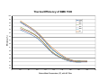
Thermal Efficiency of BMK 1500
100
99
100%
80%
98
60%
97
40%
20%
96
5%
Efficiency (%)
95
94
93
92
91
90
89
88
87
86
85
70
80
90
100
110
120
130
140
Return Water Temperature (°F), with 20° Rise
150
160
170
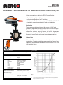
MOV-02
Product Specification
BUTTERFLY MOTORIZED VALVE (AM/GM/GK/DKRX ACTUATOR) 24V
Valves are supplied by Belimo to AERCO’s specification.
• 50 psi bubble tight shut-off
• Long stem design allows for 2” insulation
• Valve face-to-face dimensions comply with API 609 & MSS-SP-67
• Completely assembled and tested, ready for installation
Application
These valves are designed to meet the needs of HVAC and
commercial applications requiring bubble tight shut-off for liquids.
Typical applications include chiller isolation, cooling tower isolation,
change-over systems, large air handler coil control, bypass and
process control applications. The large Cv values provide for an
economical control valve solution for larger flow applications.
Jobsite Note
Valves should be stored in a weather protected area prior to
construction. Complete installation recommendations can be found
in Belimo’s Installationand Maintenance Instructions for F6/F7 HD/
HDU Butterfly Valves.
Valve Technical Data
Flow Pattern
Service
chilled, hot water, 60% glycol
Flow Characteristic
modified equal percentage
Action
90° rotation
Type of End Fitting
for use with ANSI Class 125/150
flanges
Materials
Body
Body finish
Disc
Seat
Shaft
O-ring
Upper bushing
Middle bushings
Lower bushing
ductile iron ASTM A536
epoxy powder coated
304 stainless steel
EPDM
416 stainless steel
EPDM
RPTFE
RPTFE
RPTFE
Media Temperature Range
-22°F to 250°F [-30°C to 120°C]
Operation Ambient
Temperature Range
-22°F to 122°F [-30°C to 50°C]
Body Pressure Rating
ASME/ ANSI Class 125/150
(200 psi at -30°F to 275°F)
Rangeability
10:1 (for 30° to 70° range)
Maximum Velocity
12 FPS
Application Notes
1.
2.
3.
Valves are rated at 50 psi differential pressure in the closed position.
Valves are furnished with lugs tapped for use with ANSI Class 125/150 flanges. Installation
flanges and hardware are not included.
2-way assemblies are furnished assembled and tested, ready for installation.
Operation
Actuator Technical Data
Power Supply
24VAC ±20% 50/60Hz
24VDC ±10%
The actuator is electronically protected against overload.
Power consumption
AMX
GMX
GKX
DKRX
Running (Holding)
3.5 W (1.3 W)
4.5 W (1.5 W)
12 W (3 W)
12
(3W)
The AMX, GMX, and GKX series actuators provide 95° (DKRX:90°) of rotation and
a visual indicator shows the position of the actuator. When reaching the damper or
actuator end position the actuator automatically stops. The gear can be manually
disengaged by pressing the button located on the actuator cover.
Transformer sizing
AMX
GMX
GKX/DKRX
6 VA Class 2 power source
7 VA Class 2 power source
21 VA Class 2 power source
Electrical connection
18 GA plenum rated cable
½” conduit connector
protected NEMA 2 (IP54)
3 ft [1m]
DKRX = Screw Terminal
(for 22 to 12 AWG wire)
Overload protection
electronic throughout 0 to 95 rotation (DKRX:90°)
Operation range Y
2 to 10 VDC, 4 to 20mA (default)
variable (VDC,floating point, on/off)
Input impedance
100kΩ (0.1 mA), 500Ω
1500Ω (fl oating point, on/off)
Feedback output U
2 to 10VDC, 0.5mA max, VDC variable
Angle of rotation
max. 95° (DKRX 90°), adjustable with mechanical stop
electronically variable
Torque
AMX
GMX
GKX
DKRX
The AMX, GMX, GKX, and DKRX actuators use a brushless DC motor, which is
controlled by an Application Specific Integrated Circuit (ASIC). The ASIC monitors
and controls the actuators rotation and provides a digital rotation sensing (DRS)
function to prevent damage to the actuator in a stall condition. Power consumption is
reduced in a holding mode.
The GKX 24-MFT, and DKRX24-MFT acuator provides electrical power off operation
for reliable fail safe application.
Auxiliary switches or feedback potentiometers are provided and fastened directly
onto the actuator body for signaling and switching functions.
Complete wiring diagrams can be found in AERCO’s Technical Instructions
Document TID-0028.
DIMENSIONS
180 in-lb [20 Nm]
360 in-lb [40 Nm]
360 in-lb [40 Nm]
720 in-lb [80 Nm]
Direction of rotation
reversible with cw/ ccw switch
Fail-safe position (GKX/DKRX
Models)
adjustable with dial or tool 0 to 100% in 10% increments
Position indication
reflective visual indicator (snap-on)
Manual override
external push button
Running time
normal operation
fail-safe (GKX/DKRX
Models)
90 seconds (default) , AMX variable (90 to 350 sec), GMX
variable (75 to 300 sec), GKX variable (90 to 150 sec),
DKRX=(75 to 290 sec)
35 seconds
Humidity
5 to 95% RH non-condensing
Ambient temperature
-22°F to +122°F [-30°C to +50°C]
Storage temperature
-40°F to +176°F [-40°C to +80°C]
Housing
NEMA2, IP54, UL enclosure type 2
Housing material
UL94-5VA(AMX/GMX/GKX); DKRX = Polycarbonate
Agency list
DIMENSIONS (INCHES)
cULus acc. to UL 60730-1A/-2-14 (ALL MODELS)
CAN/CSA E60730-1:02 (AMX/GMX/GKX); CAN/CSA
E60730-1 (DKRX)
Certified to IEC/EN 60730-1 and IEC/EN 60730-2-14”
(DKRX) acc. to 2004/108/EEC and 2006/95/EC
(AMX/GMX/GKX)
AERCO
A
B
C
D (Max)
BHC
No. of Holes
Lug Bolt
92084-3
1.78
7
7
16
6
4
5/8-11UNC
92084-4
1.92
9
9
21
7.5
8
5/8-11UNC
92084-5
1.69
9
9
21.03
6
4
5/8-11UNC
92084-6
1.92
9
9
21.53
7.5
8
5/8-11UNC
92084-7
2.19
7.34
6.77
21.52
9.50
8
3/4-10UNC
Noise level
max 45dB(A)
Servicing
maintenance free
Dimension “D” allows for actuator removal without the need to remove the valve from the pipe.
Quality standard
ISO 9001
Max GPM = Maximum US galllons of water per minute, at room temperature , that will flow through
the fully open valve without exceeding design velocity limits.
Dimenson “A” is compressed, add .125” for relaxed state.
SPECIFICATIONS
AERCO
P/N
Size
Valve
Model
92084-3
3"
F680HDU
92084-4
4"
F6100HDU
92084-5
3"
F680HDU
92084-6
4"
92084-7
6”
Actuator
Model
Cv
Max
GPM
COP
Weight
(lbs)
AMX24-MFT
302
264
50
13
GMX24-MFT
600
470
50
24
GKX24-MFT
302
264
50
15
F6100HDU
GKX24-MFT
600
470
50
25
F6150HDU
DKRX24-MFT-T
1579
1058
50
45
COP = Close-Off Pressure stated in psi. This is the maximum differential pressure the valve will
close-off against while maintaining a bubble tight seal.
PROPOSAL/SUBMITTAL INFORMATION
System Data
Size
AERCO P/N
GPM
Pressure
(psig)
Temp
(F)
Represented By:
Specifications subject to change without prior notice.
Consult website or contact AERCO.
MOV-02 12/2012 NY
WATER HEATERS • BOILERS • PARTS & ACCESSORIES
AERCO INTERNATIONAL, INC.
100 ORITANI DR. • BLAUVELT, NY 10913
(845) 580-8000 • FAX (845) 580-8090
www.aerco.com
B
K
I
7
3
4"
5
2
2
1
1
2
1
2
2
2
Qty
3
6
www.bkiindustries.com
4
3
10
7
2
5
1
1
Outlet
Inlet
Date: 11-9-11
Approved by:
Revision: 1.1
Scale: None
P.O. Box 256 Walled Lake, MI 48390
Phone: 248-977-5550
Fax: 248-438-1674
BKI Industries, Inc
**Dimensions are Approximate**
**Patent Pending Design**
Made in the U.S.A
- Eliminates damage to concrete floors and cast iron drainage piping
- Active agent is crushed limestone & pelletized lime formulated mix
- All connections prepaired with low "VOC" primer and PVC-Glue
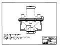
- Neutralizes flue gas condensation to a "Neutral 7.0" PH Level
For Safe Disposal to drain and sewer
- Compliance with Michigan Plumbing Code Sections 803 & 314
BTU Capacity: Up to 2000 MBH
Est. Weight: 14 lbs
8
9 6
18"
- For use on High Efficiency Condensing Gas Fired Appliances
Model: BKI-2000
PVC Schedule 40 Dip-Tube
MIP Polypropylene Screen
14 Gauge 13/16" Painted Uni-Strut
Zinc Coated Uni-Strut Clamp
PVC-DWV MIP Threaded Cap
Limestone Formulated Mix
6
7
8
9
10
3" PVC-DWV Schedule 40 C/O Tee
3" Schedule 40 DWV-PVC Pipe
5
INDUSTRIES, INC.
2
Description
Schedule 40 PVC FM x FM Coupling
3" Schedule 40 PVC CAP (Modified)
3
4
3
4"
4
3
2
Item
1
5.5"
* Unions to be field installed within 6"
of Inlet & Outlet.
* Field installed piping to be PVC,
CPVC, or Stainless Steel.
6"
Acidic Condensation Neutralization Kit
SUBMITTAL
MM-627
JOB:
REPRESENTATIVE:
UNIT TAG:
ORDER NO.
DATE:
ENGINEER:
SUBMITTED BY:
DATE:
CONTRACTOR:
DATE:
APPROVED BY:
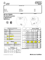
FS251
Series FS250
General Purpose
Liquid Flow
Switches
FS254
Materials of Construction
Series FS250
Part
Specifications
Wetted Body
Brass
Paddle arm
Brass
Pipe Size
NPT
(in.)
Pivot Pin
Brass
1"
O-ring
EPDM
Paddles
Stainless Steel
1-1/4"
Housing Base
FS251
FS254
Aluminized Steel
1-1/2"
Aluminum
Housing Cover
2"
FS251
Polycarbonate
FS254
Aluminum
2-1/2"
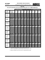
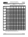
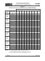
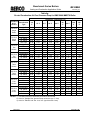
Ratings
3"
FS251
NEMA-1
FS254
NEMA-4
4"
Maximum Operating Pressure
160 psig (11.0 bar)
Maximum Temperature
250°F (121 °C)
6"
Motor Switch Rating
(Amperes)
Voltage
Full Load
Locked
Rotor
120VAC
7.4
44.4
240 VAC
3.7
22.2
© COPYRIGHT 2007 ITT Corporation
5"
Flow
Adjustment
Setting
Flow
gpm
(lpm)
No Flow
gpm
(lpm)
Max Flow
Rate (gpm)
(lpm)†
Minimum
5.8 (22)
5.1 (19)
27
Maximum
12.6 (48)
11.9 (45)
(102)
Minimum
6.7 (25)
6.0 (23)
47
Maximum
19.1 (72)
18.0 (68)
(178)
Minimum
8.4 (32)
7.0 (26)
63
Maximum
25.3 (96)
24.1 (91)
(238)
Minimum
12.9 (49)
11.2 (42)
105
Maximum
31.5 (119)
30.2 (114)
(397)
Minimum
17.9 (68)
14.5 (55)
149
Maximum
43.2 (164)
40.0 (151)
(564)
Minimum
26.2 (99)
20.2 (76)
230
Maximum
54.9 (208)
49.8 (188)
(871)
Minimum
42.0 (159)
33.7 (128)
397
Maximum
75.6 (286)
68.0 (257)
(1503)
Minimum
54.6 (207)
46.7 (177)
654
Maximum
109.4 (414)
98.4 (372)
(2475)
Minimum
67.7 (256)
60.2 (228)
900
Maximum
131.1 (496)
123.5 (467)
(3407)
† Without Paddle Damage
Pilot Duty
125 VA at
120
or 240 VAC
50 or 60 cycles
McDonnell & Miller
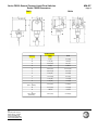
Series FS250 General Purpose Liquid Flow Switches
Series FS250 Dimensions
FS251
MM-627
Page 2
FS254
Dimensions
Reference
FS251
FS254
A
3 (76)
3-1/4 (83)
B
1-1/2 (38)
1-5/8 (41)
C
2-7/32 (56)
3/4 (19)
D
7/8 (22)
1/2 NPTF
E
6-3/8 (162)
6-3/16 (157)
F
2-15/16 (75)
2-3/4 (70)
G
3-3/8 (86)
3-7/8 (98)
H
1-11/16 (43)
2-1/4 (57)
J
1-1/2 (38)
1-1/2 (38)
K
1-1/8 (29)
1-1/8 (29)
3-7/16 (87)
3-7/16 (87)
M
2-1/16 (52)
1-7/8 (48)
N
1" NPTM
1" NPTM
2-5/16 (59)
2-5/16 (59)
L
(with 1" paddle)
P
Turn-in Radius
(not shown)
ITT
8200 N. Austin Avenue
Morton Grove, IL 60053
Phone (847)966-3700
Facsimile (847)966-9052
www.mcdonnellmiller.com
GF-2030
Benchmark Series Boilers
Gas Supply Design Guide
TAG-0047_0G
GAS SUPPLY DESIGN GUIDE
Natural Gas, Propane Gas, or
Dual Fuel Fired Modulating,
Condensing Boilers
BENCHMARK Series
Gas-Fired Boilers
For models:
BMK750 to BMK6000
Last Update: 10/04/2013
PR1 10/04/13
AERCO International, Inc. • 100 Oritani Dr. • Blauvelt, New York 10913 • Phone: 800-526-0288
Page 1 of 10
GF-2030
TAG-0047_0G
Benchmark Series Boilers
Gas Supply Design Guide
Technical Support:
(Mon–Fri, 8am-5pm EST)
1-800-526-0288
www.aerco.com
Disclaimer
The information contained in this manual is subject to change without notice from AERCO International, Inc. AERCO
makes no warranty of any kind with respect to this material, including but not limited to implied warranties of
merchantability and fitness for a particular application. AERCO International is not liable for errors appearing in this
manual. Nor for incidental or consequential damages occurring in connection with the furnishing, performance, or use
of this material.
PR1 10/04/13
AERCO International, Inc. • 100 Oritani Dr. • Blauvelt, New York 10913 • Phone: 800-526-0288
Page 2 of 10
GF-2030
TAG-0047_0G
Benchmark Series Boilers
Gas Supply Design Guide
GENERAL
AERCO Benchmark Low NOx gas fired boilers are modulating input devices that require an adequate volume of natural
gas at constant pressure for proper operation. The gas requirements specified in this document must be satisfied to
ensure efficient combustion. Designers and installers must adhere to the AERCO specifications and those of the local
authorities having jurisdiction. A thorough understanding and knowledge of these guidelines is required for the
successful design and installation of Benchmark Low NOx series boilers.
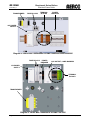
Gas Train Components
AERCO Benchmark gas-fired boilers are equipped with standard UL approved/FM compliant gas trains. These gas
trains are factory tested and fired, with a minimum number of modular components. The gas train components have
been designed to operate at high combustion efficiencies by closely controlling both the volume and air/fuel mixture to
the burner. The major internal gas train components are:
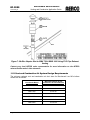
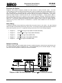
∗ SAFETY SHUT OFF VALVE (SSOV) With BUILT-IN SUPPLY GAS REGULATOR - An electro-hydraulic gas valve,
containing a proof of closure switch, is utilized to stop fuel from flowing into the gas train of the boiler. This is a 100%
tight shutoff device with a visible window indicator showing valve position. Reliable, and a standard industry
component, this valve is factory piped with a low gas pressure switch on the inlet side of the valve which monitors the
manifold pressure for minimum supply conditions. There is also a high gas pressure switch installed on the outlet side
of the gas valve, which shuts down the boiler if gas manifold pressures exceed maximum conditions. On all BMK750
to BMK 3000 models, the actuator has a built-in regulator that replaces the need for an external supply regulator for
installations that have supply pressure of up to 14.0” W.C. This does not apply to the BMK 6000 units, which have a
minimum supply pressure of 14” W.C. For installations that have supply pressure greater than 14.0” W.C., see the
“Gas Pressure Requirements” section.
∗ AIR/FUEL VALVE - The air/fuel valve controls the volume and mixture of air and fuel in perfect proportion throughout
the entire modulation range of the boiler. The valve utilizes one common shaft to simultaneously vary the gas port
area and air volume. The gas portion of the valve is a slide port type valve with linear proportion-to-position
characteristics. The air side uses a butterfly type valve for adjusting the air volume. The driver of the valve shaft is a
precision stepping motor which provides continuous positioning from full input to minimum fire. The air/fuel valve also
contains two proof-of-position switches.
∗ CAST ALUMINUM BLOWER ASSEMBLY - A cast aluminum pre-mix blower ensures the precise mixing of air and
fuel prior to entering the burner thereby providing controlled combustion.
* LOW NOx BURNER – The burner provides the actual point of air/fuel contact and combustion into the cylindrical
combustion/heat exchanger. Fabricated from metal fiber mesh covering a stainless steel body, the burner is stable
throughout the entire input range of the boiler. The spark igniter and flame detector for the combustion supervision
system are part of this assembly. The burner is easily removable from the boiler.
GAS PRESSURE REQUIREMENTS
AERCO Benchmark Low NOx series boilers require a stable natural gas and propane input pressure. For Benchmark
Models BMK 750 through BMK 3000, the nominal inlet supply pressure to the boiler is 7.0” W.C. The allowable gas
inlet pressure range is 4.0” W.C. (min.) to 14.0” W.C. (max.) when firing at maximum input, except for the BMK 750
and BMK 1000 when operating with propane, in which case the minimum propane inlet pressure is 7.0” W.C.
for the BMK 750 and 10.0” W.C. for the BMK 1000. A low supply gas pressure switch in each gas train prevents the
boiler from operating without sufficient pressure. Maximum allowable gas pressure is 14.0” W.C. for BMK 750 through
BMK 3000 boiler sizes. Gas pressure should be measured when the unit is in operation (firing). Measure the gas
pressure with a manometer at the 1/8” NPT ball valve provided at the SSOV inlet. In a multiple boiler installation, gas
pressure should initially be set for single boiler operation, and then the remaining boilers should be staged on at full
fire, to insure gas pressures never fall below the supply gas pressure when the single unit was firing.
The Benchmark BMK 6000 Model requires a minimum stable gas pressure of 14” W.C. The maximum allowable gas
pressure for the BMK 6000 is 2.0 psig. As with all other BMK sizes, a low supply gas pressure switch is provided in the
gas train to prevent operation without sufficient gas pressure.
PR1 10/04/13
AERCO International, Inc. • 100 Oritani Dr. • Blauvelt, New York 10913 • Phone: 800-526-0288
Page 3 of 10
GF-2030
TAG-0047_0G
Benchmark Series Boilers
Gas Supply Design Guide
An external isolation valve must be installed at each Benchmark Low NOx boiler, as shown in Diagram 1. This isolation
valve is supplied with the boiler. For installations that have greater than 14.0” W.C. supply pressure, an external lockup type regulator must be installed downstream of the isolation valve. The lock-up type regulator(s) must be sized as
follows
Boiler Size (MBH)
750
1000
1500
2000
2500
3000
6000
Required CFH
750 – 850
1000 – 1200
1500 – 1750
2000 – 2300
2500 – 2850
3000 – 3400
6000 – 6500
External gas regulators are self-contained with tapped diaphragm vent ports allowing the diaphragm to change its
position as required. These vents typically require piping to the outside. For details, refer to the paragraph titled
“Venting of Gas Supply Regulators” on page 9 of this guide. The SSOV/Regulator in the gas train is factory piped
and does not require any vent piping.
CAUTION
AERCO BOILERS MUST BE ISOLATED FROM THE
SYSTEM WHEN LEAK TESTING.
Drip legs are typically required at the gas supply of each boiler to prevent any dirt, weld slag, or debris from entering the
boiler gas train inlet pipe. When multiple boilers are installed, some utilities and local codes require a full size drip leg
on the main gas supply line in addition to the drip leg at each unit. The bottom of the gas drip leg(s) should be
removable without disassembling any gas piping. The weight of the gas pipe should not be supported from the bottom
of the drip leg. The drip leg(s) should not be used to support any or part of the gas piping.
PR1 10/04/13
AERCO International, Inc. • 100 Oritani Dr. • Blauvelt, New York 10913 • Phone: 800-526-0288
Page 4 of 10
GF-2030
Benchmark Series Boilers
Gas Supply Design Guide
TAG-0047_0G
GAS
PRESSURE
REGULATOR
NATURAL
GAS
SUPPLY
(Required for
Massachusetts
installations)
MANUAL
SHUTOFF
VALVE
Diagram 1. Single Boiler Gas Pipe Connections (BMK 2000 Shown)
CUSTOM GAS TRAINS
Some utilities, insurance carriers, and industrial customers have special requirement gas components on high input
devices beyond that which are normally supplied with AERCO boilers. Secondary shutoffs, high or low pressure
operators, and external regulators are typical of the requirements of gas utilities. It is mandatory that a designer or
installer comply with these requirements. AERCO assumes no liability when these requirements are not satisfied for
any location or installation. Contact your local gas utility for their specific requirements before installing AERCO
equipment. Special gas trains with a double block and bleed (DBB) configuration (formerly IRI) are available from
AERCO.
The minimum gas inlet pressure requirements for natural gas (N.G.) and propane (LPG) are as follows:
Minimum Gas Inlet Pressure Requirements for Natural Gas and Propane
Gas Train
BMK 750
BMK 1000
BMK 1500
BMK 2500
BMK 3000
N.G.
5.0”
W.C.
LPG
5.0”
W.C.
N.G.
4.5”
W.C.
LPG
4.5”
W.C.
N/A
N/A
N/A
N/A
N/A
N/A
N/A
N/A
N/A
N/A
N.G.
4.5”
W.C.
4”
W.C.
4”
W.C.
N.G.
4.5”
W.C.
LPG
7”
W.C.
N.G.
4.5”
W.C.
LPG
10”
W.C.
N.G.
4.5”
W.C.
LPG
Dual Fuel
N/A
N/A
N/A
N/A
N/A
Dual Fuel
DBB (IRI)
N/A
N/A
N/A
N/A
N/A
DBB (IRI)
PR1 10/04/13
---
BMK 2000
AERCO International, Inc. • 100 Oritani Dr. • Blauvelt, New York 10913 • Phone: 800-526-0288
LPG
4.5”
W.C.
8”
W.C.
8”
W.C.
BMK 6000
N.G.
14”
W.C.
14”
W.C.
14”
W.C.
LPG
10.5”
W.C.
10.5”
W.C.
10.5”
W.C.
Page 5 of 10
GF-2030
Benchmark Series Boilers
Gas Supply Design Guide
TAG-0047_0G
GAS PIPING
All gas piping and components must comply with NFPA local codes, and utility requirements minimum. Only gas
approved fittings, valves, or pipe should be utilized.
Standard industry practice for gas piping is Schedule 40 iron pipe and fittings. All high and low gas pressure piping
systems must comply with local utility and building codes.
Assembled piping should be clean of all debris, pipe chips, or foreign material to prevent any from entering the
Innovation Low NOx series boiler gas train. Piping should be tested as prescribed in NFPA 54. Equipment should be
isolated before testing any piping system over the allowable pressure. DO NOT EXCEED 14.0” W.C. on the inlet side
of the Benchmark boiler at any time for BMK 750 through BMK 3000 Models. For BMK 6000 boilers, DO NOT
EXCEED 2.0 P.S.I. on the inlet side of the boiler at any time.
GAS SUPPLY MAIN SIZING
Gas pipe sizing, for either a single or multiple boiler installation, shall be sized for a maximum pressure drop of 0.3”
W.C., from the source to the final boiler. The maximum gas flow rate required is the sum of the maximum inputs of
each unit divided by the heat of combustion of the fuel supplied at the location, (approximately 1,030 BTU per cubic foot
for natural gas or 2,520 BTU per cubic foot for propane gas). The fuel supplier or utility should be consulted to confirm
that sufficient volume and normal pressure is provided to the building at the discharge side of the gas meter or supply
pipe. For existing installations with gas equipment, gas pressure should be measured with a manometer to be certain
sufficient pressure is available. Before sizing gas piping, a survey of all connected gas devices should be made. Gas
piping supplying more than one gas device must be able to handle the total connected input within the allowable gas
pressure drop. The allowable minimum and maximum gas pressure for each device should be considered. Whenever
the minimum and maximum gas pressures vary between devices, gas pressure regulators at each unit should be
installed to allow regulation at any individual unit. Gas pressure must never exceed the maximum allowable rating of
any connected device.
The total length of gas piping as well as fitting pressure drop must be considered when sizing the gas piping. Total
equivalent length should be calculated from the meter or source location to the last boiler connected on the header.
The Gas Piping Tables 1, 2 and 3 (see below) containing data extracted from NFPA 54 should be used as a minimum
guideline. Gas pipe size should be selected on the total equivalent length from the appropriate pressure table. The gas
volume for cfh flow will be the input divided by the calorific value of the fuel to be supplied.
GAS HEADER SIZING
Main supply gas pipe sizing should be developed for the total plant. Boiler gas manifold piping should be sized based
on the volume requirements and lengths between boilers and the fuel main. Multiple boiler manifold sizing (Diagram 2)
indicates the proper sizing for units placed on the factory standard 52” centers with 2” takeoffs for each unit. Header
sizes can be either full size or stepped in size as units are connected. A typical gas piping header diagram for a 3Module Benchmark Boiler Plant is illustrated in Diagram 3.
BENCHMARK SERIES GAS HEADER SIZING
No. of Boilers
1
2
3
4
5
6
7
8
Sch. 40 Iron Pipe
2”
4”
4”
4”
5”
5”
6”
6”
Diagram 2. Multiple Boiler Manifold Chart *
* Depending on gas piping layout. See Gas Piping Tables 1 – 4, below.
PR1 10/04/13
AERCO International, Inc. • 100 Oritani Dr. • Blauvelt, New York 10913 • Phone: 800-526-0288
Page 6 of 10
GF-2030
TAG-0047_0G
Benchmark Series Boilers
Gas Supply Design Guide
MANUAL
SHUTOFF
VALVE (TYP.)
GAS SUPPLY
GAS
PRESSURE
REGULATOR
(TYP.)*
*
NOTE
A supply gas regulator is
required on each boiler gas
inlet only for Massachusetts
installations.
DIRT
TRAP
(TYP.)
Diagram 3: Typical Multiple Boiler Manifold Construction
*Based on Table 1 on the following page for natural gas, 0.6 specific gravity, 1,000 cfh/unit, actual header sizes will
vary with length of pipe run and fittings employed. For propane gas (1.6 specific gravity, 2,520 BTU/FT3) header
sizing, consult NFPA 54.
If supply gas pressure exceeds 14.0” W.C., a single header gas manifold lock-up type regulator, -or- individual lock-up
regulators can be used to bring the gas pressure down to 14.0” W.C. Header should be located above or behind boiler.
Gas piping should not be installed directly over top or front of any part of boiler. Sufficient clearances for maintenance
are required.
PR1 10/04/13
AERCO International, Inc. • 100 Oritani Dr. • Blauvelt, New York 10913 • Phone: 800-526-0288
Page 7 of 10
GF-2030
Benchmark Series Boilers
Gas Supply Design Guide
TAG-0047_0G
GAS PIPING TABLES
The data in the following pipe and vent sizing tables have been extracted from the National Fire Protection
Association Article 54 (NFPA 54)
TABLE 1
Maximum Capacity of Pipe in Cubic Feet of Gas per Hour for Gas Pressures of 0.5 psi or Less
and a Pressure Drop of 0.3 inch Water Column
Nominal
Iron Pipe Internal
Size
Diameter
(Inches) (Inches)
Total Equivalent Length of Pipe (Feet)
10
20
30
40
50
60
70
80
90
125
150
175
200
990
930
780
710
650
610
2.00
2.067
3,050
2,100
1,650 1,450 1,270 1,150 1,050
2.50
2.469
4,800
3,300
2,700 2,300 2,000 1,850 1,700 1,600
1,500
1,250
1,130
1,050
980
3.00
3.068
8,500
5,900
4,700 4,100 3,600 3,250 3,000 2,800
2,600
2,200
2,000
1,850
1,700
4.00
4.026
17,500 12,000 9,700 8,300 7,400 6,800 6,200 5,800
5,400
4,500
4,100
3,800
3,500
TABLE 2
Pipe Sizing Table for 1 Pound Pressure Capacity of Pipes of Different Diameters and Lengths in Cubic
Feet per Hour for an Initial Pressure of 1.0 psi with a 10% Pressure Drop and a Gas of 0.6 Specific Gravity
Pipe Size of
Schedule 40
Standard Pipe
(Inches)
Total Equivalent Length of Pipe (Feet)
Internal
Diameter
(Inches)
50
100
150
200
250
300
400
500
2.00
2.067
4245
2918
2343
2005
1777
1610
1378
1222
2.50
2.469
6766
4651
3735
3196
2833
2567
2197
1947
3.00
3.068
11962
8221
6602
5650
5008
4538
3884
3442
3.50
3.548
17514
12037
9666
8273
7332
6644
5686
5039
4.00
4.026
24398
16769
13466
11525
10214
9255
7921
7020
5.00
5.047
44140
30337
24362
20851
18479
16744
14330
12701
6.00
6.065
71473
49123
39447
33762
29923
27112
23204
20566
8.00
7.981
146849
100929
81049
69368
61479
55705
47676
42254
TABLE 3
Pipe Sizing Table for 2 Pounds Pressure Capacity of Pipes of Different Diameters and Lengths in Cubic
Feet per Hour for an Initial Pressure of 2.0 psi with a 10% Pressure Drop and a Gas of 0.6 Specific Gravity
Pipe Size of
Schedule 40
Standard Pipe
(Inches)
Internal
Diameter
(Inches)
50
100
150
200
250
300
400
500
2.00
2.067
6589
4528
3636
3112
2758
2499
2139
1896
2.50
2.469
10501
7217
5796
4961
4396
3983
3409
3022
3.00
3.068
18564
12759
10246
8769
7772
7042
6027
5342
3.50
3.548
27181
18681
15002
12840
11379
10311
8825
7821
4.00
4.026
37865
26025
20899
17887
15853
14364
12293
10895
5.00
5.047
68504
47082
37809
32359
28680
25986
22240
19711
6.00
6.065
110924
76237
61221
52397
46439
42077
36012
31917
PR1 10/04/13
Total Equivalent Length of Pipe (Feet)
AERCO International, Inc. • 100 Oritani Dr. • Blauvelt, New York 10913 • Phone: 800-526-0288
Page 8 of 10
GF-2030
Benchmark Series Boilers
Gas Supply Design Guide
TAG-0047_0G
TABLE 4
Pipe Sizing Table for 5 Pounds Pressure Capacity of Pipes of Different Diameters and Lengths in Cubic
Feet per Hour for an Initial Pressure of 5.0 psi with a 10% Pressure Drop and a Gas of 0.6 Specific Gravity
Pipe Size of
Schedule 40
Standard Pipe
(Inches)
Internal
Diameter
(Inches)
50
100
150
200
250
300
400
500
2.00
2.067
11786
8101
6505
5567
4934
4471
3827
3391
2.50
2.469
18785
12911
10368
8874
7865
7126
6099
5405
3.00
3.068
33209
22824
18329
15687
13903
12597
10782
9556
3.50
3.548
48623
33418
26836
22968
20365
18444
15786
13991
4.00
4.026
67736
46555
37385
31997
28358
25694
21991
19490
5.00
5.047
122544
84224
67635
57887
51304
46485
39785
35261
6.00
6.065
198427
136378
109516
93732
83073
75270
64421
57095
Total Equivalent Length of Pipe (Feet)
VENTING OF GAS SUPPLY REGULATORS
AERCO’s general guidelines for venting of gas regulators are listed below. AERCO recommends that these guidelines
be followed to ensure the most reliable and proper operation of AERCO gas fired equipment. It is also recommended
that you consult local codes and the gas regulator manufacturer for additional details. Always follow the most stringent
guidelines available, including those listed below.
• When venting a gas supply regulator, the vent pipe must be no smaller than the regulator vent size.
• In a multiple unit installation, each regulator must have a separate vent line.
• Vent lines must not be manifolded together or with any other equipment at the site that also requires
atmospheric vents.
• When sizing the vent, pipe diameters must be increased by one pipe diameter every 20 equivalent feet of
pipe.
Each 90° elbow is equivalent to approximately:
⇒ 2.5 feet for nominal pipe sizes of up to 3/4”
⇒ 4.5 feet for nominal pipe sizes of up to 1-1/2”
⇒ 10.5 feet for nominal pipe sizes of up to 4”
Each 45° elbow is equivalent to approximately:
⇒ 1 foot for nominal pipe sizes of up to 3/4”
⇒ 2 feet for nominal pipe sizes of up to 1-1/2”
⇒ 5 feet for nominal pipe sizes of up to 4”
PR1 10/04/13
AERCO International, Inc. • 100 Oritani Dr. • Blauvelt, New York 10913 • Phone: 800-526-0288
Page 9 of 10
GF-2030
Benchmark Series Boilers
Gas Supply Design Guide
TAG-0047_0G
Change Log
Date
Description
Changed By
09/03/2013
Rev F: Removed refs to BMK1.5/2.0, changed all
images, added references to 1500, 2000, 2500 units.
Curtis Harvey
10/04/2013
Rev G: Modified 2 drawings to remove multiple dirt traps
(installations have 1 dirt trap per gas input line, not per
unit) per PIR 936.
Chris Blair
© AERCO International, Inc., 2013
Visit Us at www.aerco.com
PR1 10/04/13
AERCO International, Inc. • 100 Oritani Dr. • Blauvelt, New York 10913 • Phone: 800-526-0288
Page 10 of 10
Benchmark Series Boilers
GF-2050
Venting and Combustion Application Guide
TAG-0022_0S
VENTING AND COMBUSTION AIR GUIDE
Natural Gas, Propane Gas, or
Dual Fuel Fired Modulating,
Condensing Boilers
Benchmark Series
Gas Fired Boilers
For models:
BMK 750 to BMK 6000
Revised: 12/03/2013
AERCO International, Inc. • 100 Oritani Dr. • Blauvelt, New York 10913 • Phone: 800-526-0288
GF-2050
TAG-0022_0S
Benchmark Series Boilers
Venting and Combustion Application Guide
Technical Support:
(Mon–Fri, 8am-5pm EST)
1-800-526-0288
www.aerco.com
Disclaimer
The information contained in this manual is subject to change without notice from AERCO International,
Inc. AERCO makes no warranty of any kind with respect to this material, including but not limited to
implied warranties of merchantability and fitness for a particular application. AERCO International is not
liable for errors appearing in this manual. Nor for incidental or consequential damages occurring in
connection with the furnishing, performance, or use of this material.
Page 2 of 40
AERCO International, Inc. • 100 Oritani Dr. • Blauvelt, NY 10913 • Ph: 800-526-0288
12/03/2013
Benchmark Series Boilers
Venting and Combustion Application Guide
GF-2050
TAG-0022_0S
Table of Contents
1.1
1.2
1.3
1.4
1.5
1.6
1.7
1.8
1.9
1.10
1.11
1.12
1.13
1.14
1.15
1.16
1.17
1.18
1.19
1.20
1.21
1.22
1.23
1.24
12/03/2013
General .................................................................................................................... 4
Materials and Approvals ......................................................................................... 4
Code Required Vent Terminations ......................................................................... 4
Combustion Air Supply .......................................................................................... 6
Combustion Air from WITHIN the Building ......................................................... 7
Combustion Air from OUTSIDE the Building ....................................................... 8
Two-Permanent-Openings Method (USA Only) .................................................... 8
One Permanent Opening Method.......................................................................... 11
Opening a Louver Through the Benchmark Boiler .............................................. 12
Direct Vent/Ducted Combustion Air .................................................................... 13
Exhaust Vent and Combustion Air Systems ......................................................... 13
Gross Natural Draft ............................................................................................... 14
Acceptable Pressure Ranges ................................................................................. 14
Exhaust Fans ......................................................................................................... 14
Corrections for Altitude ........................................................................................ 14
Manifolded Systems.............................................................................................. 15
Elbow Quantity and Separation ............................................................................ 15
Exhaust Muffler And Air Inlet Attenuator Guidelines ......................................... 15
Vent and Combustion Air System Design Requirements ..................................... 16
Condensate Removal ............................................................................................ 20
Individually Vented Systems ................................................................................ 21
1.21.1 BMK 1500 Example: .............................................................................. 22
Manifolded Ducted Combustion Air .................................................................... 23
Common Vent Breeching (Manifolded) ............................................................... 25
Pressure Drop and Draft Data Tables ................................................................... 27
AERCO International, Inc. • 100 Oritani Dr. • Blauvelt, NY 10913 • Ph: 800-526-0288
Page 3 of 40
GF-2050
TAG-0022_0S
1.1
Benchmark Series Boilers
Venting and Combustion Application Guide
General
The AERCO Benchmark gas-fired boiler is a high efficiency, forced draft, hydronic-heating unit
with unique venting capabilities. All Benchmark venting options (which include horizontal and
vertical discharges, direct vent, and manifolded vent breeching), typically exceed the
capabilities of competing combustion equipment. These and other features enable Benchmark
boilers to provide extremely high thermal efficiencies and optimum temperature control under
widely varying conditions. It is therefore critical that the flue gas vent and combustion air
system be designed to maintain these objectives.
Benchmark’s high efficiency is achieved through air/fuel modulation and the release of energy
from the moisture condensing in the combustion products. Because condensation can occur
in the exhaust vent system, means must be provided to remove the moisture accumulation.
Each Benchmark model is fitted with a condensate removal trap, as indicated in Figures 1a –
1d, which illustrate the air inlet, vent connections and condensate removal connections for the
BMK 750 (0.75 MMBTU), BMK 1000 (1.0 MMBTU), BMK 1500 (1.5 MMBTU), BMK 2000
(2.0 MMBTU), BMK 2500 (2.5 MMBTU), BMK 3000 (3.0 MMBTU) and BMK 6000 (6.0
MMBTU) models.
The design guidelines in this bulletin provide broad latitude while meeting the objectives of
safety, longevity and optimum performance.
1.2
Materials and Approvals
The Benchmark boiler is a Category II, III, and IV appliance that requires special attention to
exhaust venting and combustion air details. The exhaust vent MUST be UL listed for use with
Category II, III, and IV appliances. The BMK 2500 and BMK 3000 can be used with
polypropylene venting materials, but NOT PVC or CPVC. The smaller size BMK 750 and BMK
1000 boilers can be used with AL29-4C, VP1738A polypropylene, PVC or CPVC vent materials,
due to their lower exhaust operating temperatures. If needed, a PVC Vent Adapter is provided in
the Spares Kit included with each BMK 750 and BMK 1000 boiler. The BMK 6000 must use ULlisted vents made of AL29-4C stainless steel. Proper clearances to combustibles must be
maintained per UL and the vent manufacturer requirements.
The UL, National Fuel Gas Code (ANSI Z223.1/ NFPA54)1 and CSA B149.1-10 guidelines are
often the basis for state and local codes. AERCO's recommendations follow the guidelines of
these agencies, unless more stringent codes govern the installation site. The venting and
combustion air systems must meet all applicable code requirements.
All Canada installations must comply with CSA B149.1 installation code.
1.3
Code Required Vent Terminations
The guidelines provided in this bulletin should be followed to comply with AERCO, UL, NFPA 54
(National Fuel Gas Code, ANSI Z223.1) and in Canada: CSA B149.1-10 recommendations and
regulations.
Vent terminations should be at least 4 feet below, 1 foot above or 4 feet removed horizontally
from any window, door or gravity air inlet of a building. Such terminations should extend beyond
the outside face of the wall by at least 6 inches.
Page 4 of 40
AERCO International, Inc. • 100 Oritani Dr. • Blauvelt, NY 10913 • Ph: 800-526-0288
12/03/2013
GF-2050
Benchmark Series Boilers
Venting and Combustion Application Guide
TAG-0022_0S
AIR INLET
AIR INLET
EXHAUST VENT
CONNECTION
EXHAUST VENT
CONNECTION
CONDENSATE
TRAP
CONDENSATE
TRAP
Figure 1a: BMK 750/1000
Figure 1b: BMK 1500/2000
AIR INLET
AIR INLET
EXHAUST VENT
CONNECTION
EXHAUST VENT
CONNECTION
CONDENSATE
TRAP
Figure 1c: BMK 2500/3000
12/03/2013
CONDENSATE
TRAP
Figure 1d: BMK 6000
AERCO International, Inc. • 100 Oritani Dr. • Blauvelt, NY 10913 • Ph: 800-526-0288
Page 5 of 40
GF-2050
TAG-0022_0S
Benchmark Series Boilers
Venting and Combustion Application Guide
The bottom of the vent termination should be at least 12 inches above both finished grade and
any maximum snow accumulation level to avoid blocking the vent or air intake. The vent
termination should be least 3 feet above any forced-air building inlet within 10 feet. Design must
prevent flue gases from recirculating through the boiler air intake.
Vents should not terminate over public walkways or areas where condensate or vapor could
create a nuisance or be detrimental to the operation of regulators, meters or related equipment.
Discharges should not be located in high wind, wind-blocked areas or corners, or be located
directly behind vegetation. Discharges in these locations may cause the flue pressures to
fluctuate and result in flame instability. As a general rule, designs should minimize wind effects.
Wall and roof penetrations should follow all applicable codes and the vent manufacturer's
instructions. Vents should never be installed at less than required clearances to combustible
materials, as enumerated in UL, NFPA, CSA B149.1-10 or local codes "Double-wall" or
'Thimble" assemblies are required when vents penetrate combustible walls or roofs.
Vertical discharges should extend at least 3 feet above the roof through properly flashed
penetrations, and at least 2 feet above any object within a 10-foot horizontal distance.
Vertical and horizontal discharges should be designed to prevent rain from entering the vent.
Large-mesh screens can be applied to protect against the entry of foreign objects but the 'free
area' should be at least twice the flue cross-sectional area.
If the vent system is to be connected to an existing stack, the stack must be UL listed for
Category II, III, and IV appliances (capable of 480°F, positive pressure and condensing flue gas
operation). Masonry stacks must be lined, and the vent penetration must terminate flush with,
and be sealed to, this liner. Vents may enter the stack through the bottom or side. All side
connections must enter at a 45-degree connection in the direction of flow and must enter at
different elevations, with the smallest vent connection at the highest elevation. Benchmark vents
must not be connected to other manufacturer’s equipment.
The exhaust vent must be pitched upward toward the termination by a minimum of ¼ inch per
foot of length. Condensate must flow back to the Benchmark unit freely, without accumulating in
the vent.
1.4
Combustion Air Supply
The Benchmark boilers require the following combustion air volumes when operated at full
capacity.
•
•
•
•
•
•
•
BMK 750
BMK 1000
BMK 1500
BMK 2000
BMK 2500
BMK 3000
BMK 6000
165 SCFM
200 SCFM
325 SCFM
500 SCFM
600 SCFM
700 SCFM
1400 SCFM
These flows MUST be accommodated. Air supply is a direct requirement of NFPA, CSA B149.110 (Canada) and local codes that should be consulted for correct design implementation.
In equipment rooms containing other air-consuming equipment ― including air compressors
Page 6 of 40
AERCO International, Inc. • 100 Oritani Dr. • Blauvelt, NY 10913 • Ph: 800-526-0288
12/03/2013
Benchmark Series Boilers
Venting and Combustion Application Guide
GF-2050
TAG-0022_0S
and other combustion equipment ― the combustion air supply system must be designed to
accommodate all such equipment when all are operating simultaneously at maximum capacity.
Combustion air intakes must be located in areas that will not induce excessive (>0.10" water
column (W.C.)) intake air pressure fluctuations. Designs should take into account equipment
blowers and exhausts when using room air for combustion.
Intakes should be located to prevent infiltration of chlorides, halogens or any other chemicals
that would be detrimental to the operation of combustion equipment. Common sources of these
compounds are swimming pools, degreasing compounds, salts, plastic processing and
refrigerants. When the environment contains these types of chemicals, the air MUST be
supplied from the outdoors using direct-vent/ducted-combustion ductwork.
Air intakes must not be located in the proximity of garages, industrial and medical hood venting,
loading docks or refrigerant vent lines. Boilers should not be installed in the proximity of
activities that generate dust if that dust can enter the boiler intake. Boilers should be located to
prevent moisture and precipitation from entering combustion air inlets.
When a boiler is used, temporarily, to provide heat during ongoing building construction or
renovation, accumulated drywall dust, sawdust and similar particles can:
Accumulate in the unit’s combustion air intake and block combustion air flow
Accumulate over the burner surface and restrict flow of air/fuel mixture
In these situations, AERCO recommends that a disposable air intake filter be installed,
temporarily, above the boiler combustion air inlet. Air filters may be required year-round in
instances in which dust or debris can enter the combustion air tube. Consult the boiler
Operations and Maintenance Manual for details.
Combustion air temperatures as low as -30°F can be used without affecting the integrity of the
equipment; however, the combustion settings may require adjustment to compensate for site
conditions.
1.5
Combustion Air from WITHIN the Building
Where combustion air will originate from within the building, air must be provided to the
equipment room from two permanent openings to an interior room (or rooms). Openings
connecting indoor spaces shall be sized and located in accordance with the following:
•
•
•
Each opening shall have a minimum free area of 1 inch2 per 1,000 BTU/hr (2,200
mm2/kW) of total input rating of all appliances in the space, but not less than 100 inch2
(0.06 m2).
One opening shall commence within 12 inches (300 mm) of the top of the enclosure,
and one opening shall commence within 12 inches (300 mm) of the bottom. (See
Figure 2).
The minimum dimension of air openings shall be not less than 3 inches (80 mm).
12/03/2013
AERCO International, Inc. • 100 Oritani Dr. • Blauvelt, NY 10913 • Ph: 800-526-0288
Page 7 of 40
GF-2050
TAG-0022_0S
Benchmark Series Boilers
Venting and Combustion Application Guide
Figure 2: All Combustion Air from Adjacent Indoor Spaces through Indoor
Combustion Air Openings
1.6
Combustion Air from OUTSIDE the Building
Outdoor combustion air shall be provided through opening(s) to the outdoors in accordance with
the methods described below. The minimum dimension of air openings shall not be less than
3 inches (80 mm). The required size of the openings for combustion air shall be based upon the
net free area of each opening. When the free area through a louver, grille, or screen is known, it
shall be used to calculate the opening size required to provide the free area specified. For
additional details, consult NFPA 54, or in Canada, CSA B149.1-10, paragraphs 8.4.1 and 8.4.3.
1.7
Two-Permanent-Openings Method (USA Only)
Two permanent openings shall be provided; one commencing within 12 inches (300 mm) of the
top of the enclosure and one commencing within 12 inches (300 mm) of the bottom. The
openings shall communicate directly ― or by ducts ― with the outdoors, or spaces that freely
communicate with the outdoors, as show on the following pages:
1. When communicating directly with the outdoors, or when communicating to the outdoors
through vertical ducts, each opening shall have a minimum free area of 1 inch2 per
4,000 BTU/hr (550 mm2/kW) of total input rating of all appliances in the space (see
Figures 3 and 4).
Page 8 of 40
AERCO International, Inc. • 100 Oritani Dr. • Blauvelt, NY 10913 • Ph: 800-526-0288
12/03/2013
Benchmark Series Boilers
Venting and Combustion Application Guide
GF-2050
TAG-0022_0S
Figure 3: All Combustion Air From Outdoors - Inlet Air From Ventilated Crawl
Space and Outlet Air to Ventilated Attic
12/03/2013
AERCO International, Inc. • 100 Oritani Dr. • Blauvelt, NY 10913 • Ph: 800-526-0288
Page 9 of 40
GF-2050
TAG-0022_0S
Benchmark Series Boilers
Venting and Combustion Application Guide
Figure 4: All Combustion Air from Outdoors - Through Ventilated Attic
2. When communicating with the outdoors through horizontal ducts, each opening shall
have a minimum free area of 1 inch2 per 2,000 BTU/hr. (1100 mm2/kW) of total input
rating of all appliances in the space (see Figure 5).
Page 10 of 40
AERCO International, Inc. • 100 Oritani Dr. • Blauvelt, NY 10913 • Ph: 800-526-0288
12/03/2013
Benchmark Series Boilers
Venting and Combustion Application Guide
GF-2050
TAG-0022_0S
Figure 5: All Combustion Air from Outdoors Through Horizontal Ducts
1.8
One Permanent Opening Method
One permanent opening shall be provided, commencing within 12 inches (300 mm) of the top of
the enclosure. The appliance shall have clearances of at least 1 inches (25 mm) from the sides
and back of the appliance, and a clearance of 6 inches (150 mm) from the front. The opening
shall communicate with the outdoors directly or through a vertical or horizontal duct to the
outdoors or spaces that freely communicate with the outdoors (as shown in Figure 6) and shall
have a minimum free area as follows:
•
1 inch2 per 3,000 BTU/hr (700 mm2/kW) of the total input rating of all appliances located
in the space.
12/03/2013
AERCO International, Inc. • 100 Oritani Dr. • Blauvelt, NY 10913 • Ph: 800-526-0288
Page 11 of 40
GF-2050
TAG-0022_0S
Benchmark Series Boilers
Venting and Combustion Application Guide
Figure 6: All Combustion Air from Outdoors Through Single Combustion Air
Opening
1.9
Opening a Louver Through the Benchmark Boiler
A louver can be opened using the auxiliary relay contacts of the Benchmark boiler. These
contacts are provided by a single pole double throw (SPDT) relay that is energized when there
is a demand for heat and is de-energized after that demand is satisfied. The relay contacts are
rated for 120 VAC at 5 amps, resistive.
NOTE
Do NOT power the louver directly using the Auxiliary Relay. An
external relay (supplied by others) must be employed for this
purpose. The boiler power cannot support external accessories.
If the louver features a proof-of-open switch, it can be connected to the boiler’s delayed
interlock. The delayed interlock must be closed for the unit to fire. If the louver requires time to
open, a time-delay can be programmed to hold the start sequence of the boiler long enough for
the proof-of-open switch to make (Parameter: Aux Start On Delay — programmable from 0 to
120 seconds). If the proof-of-open switch does not prove within the programmed time frame, the
boiler will shut down.
For wiring connections and further details regarding the auxiliary relay, delayed interlock and the
Aux Start On Delay parameter, refer to the Benchmark boiler’s Operations and Maintenance
manual.
Page 12 of 40
AERCO International, Inc. • 100 Oritani Dr. • Blauvelt, NY 10913 • Ph: 800-526-0288
12/03/2013
Benchmark Series Boilers
Venting and Combustion Application Guide
GF-2050
TAG-0022_0S
If an AERCO Boiler Management System II (BMS II) is being used to manage a multiple boiler
installation, the louver can be opened using the System Start Relay of the BMS II. Refer to the
BMS II Operations and Maintenance Manual, GF-124, for wiring connections and further details.
1.10 Direct Vent/Ducted Combustion Air
The Benchmark is approved for direct vent installation; i.e., it can draw all combustion air from
the outdoors through a metal or PVC duct connected between the Benchmark unit(s) and the
outdoors. This configuration is useful for situations in which room air is insufficient or otherwise
unsuitable for combustion. The minimum ducted combustion-air duct sizes for the Benchmark
boilers are as follows:
• BMK 750 = 6-inch diameter
• BMK 1000 = 6-inch diameter
• BMK 1500 = 6-inch diameter
• BMK 2000 = 8-inch diameter
• BMK 2500 = 8-inch diameter
• BMK 3000 = 8-inch diameter
• BMK 6000 = 14-inch diameter
In many installations, the combustion air duct can be manifolded for multiple unit applications.
If the system is designed around common air intake it cannot be common exhaust.
The length and restriction of the ducted combustion duct directly impact the size, length and
restriction of the discharge venting. The direct vent air intake should be located at least 3 feet
below any vent termination within 10 feet.
A screen with mesh size not smaller than 1” x 1” must be installed at the inlet of the ducted
combustion air duct.
IMPORTANT!
COMMON BREECHING OF AIR INTAKES CAN NOT BE
COMBINED WITH COMMON BREECHING OF EXHAUSTS.
1.11 Exhaust Vent and Combustion Air Systems
The Benchmark supports several venting and combustion air options, and although the
application parameters vary, there are basic similarities among all systems. Tables 1 through 5
at the end of this Guide address the pressure drop of most applicable vent and duct fittings and
sizes. The losses in the vent exit and air duct entrance are also included.
It should be noted that flow and vent or duct diameter have the most significant effects on
overall system pressure drop. When using fittings or terminations not listed in Tables 1, 2 and 3,
consult the device manufacturer for actual pressure drop values. If rectangular duct is to be
used, consult Table 5 for a round diameter duct size that has the identical pressure drop per
length of rectangular duct.
The pressure drop values in Table 1b and 1c are in equivalent feet of 8-inch diameter exhaust
vent. Note that 1 equivalent foot of 8-inch diameter vent is equal to 0.00546-inch W.C.
12/03/2013
AERCO International, Inc. • 100 Oritani Dr. • Blauvelt, NY 10913 • Ph: 800-526-0288
Page 13 of 40
GF-2050
Benchmark Series Boilers
Venting and Combustion Application Guide
TAG-0022_0S
The pressure drop values used in Table 1a are in equivalent feet of 6-inch diameter exhaust
vent. Note that 1 equivalent foot of 6-inch diameter vent is equal to 0.00581-inch W.C.
1.12 Gross Natural Draft
Flue gases have a lower density (and are lighter) than air and will rise, creating "gross natural
draft." Gross natural draft is created when flue gases exit the vent at an elevation above the
Benchmark boiler. The amount of draft depends upon the height of the stack and the difference
between the flue gas temperature and the surrounding air temperatures (densities). Gross
natural draft values for stacks at various heights above the Benchmark unit are presented in
Table 3, Part 1 and Part 2. These draft values are based on an installation site at sea level.
Adding the gross natural draft (negative) to the vent and air system pressure drop (positive)
determines if the total system will be positive pressure or negative pressure ("net natural draft").
As with most combustion equipment, negative pressure (net natural draft) systems should be
treated differently from positive pressure systems when the discharge vents are manifolded.
Note that sidewall vent terminations, as well as some vertical terminations, are positive pressure
systems.
Contact your AERCO sales representative or AERCO International for design assistance
and approval when designing manifolded exhaust vent systems.
CAUTION!
Do NOT install a non-sealed draft control damper.
1.13 Acceptable Pressure Ranges
For individually vented units, the exhaust system must be designed so that pressure measured
at every point is in the range from -0.25” W.C. to +0.81” W.C. For common vented units, the
exhaust system must be designed so that pressure measured at every point is in the range from
-0.25” W.C. to +0.25” W.C. Pressures below -0.25” W.C. (more negative) may cause flame
instability. Pressures above +0.25” W.C. for common vented units, or +0.81 W.C. for individually
vented units (more positive), will prevent flue gases from exiting.
1.14 Exhaust Fans
If the Benchmark boiler’s exhaust system incorporates an exhaust fan, the system designer
must size the vent pipe diameters, select the fan and determine the location of the fan sensor to
maintain a -0.25” to +0.25” W.C. pressure range at the outlet of each boiler. Also, the designer
must ensure that the exhaust fan material is acceptable for use with Category IV appliances.
1.15 Corrections for Altitude
Table 4 lists correction factors for installation altitudes above sea level. These factors must be
applied to both the natural draft and pressure drops of vent and air ducts. The pressure drop
through vents and combustion air ducts will increase at higher elevations, while the natural draft
will decrease.
IMPORTANT!
MANIFOLDED SYSTEMS CANNOT BE USED FOR BOTH
COMMON BREECHING OF AIR INTAKES AND EXHAUST
VENTS.. ONLY ONE TYPE OF COMMON BREECHING (AIR
INTAKE OR EXHAUST) CAN BE USED; BUT NOT BOTH.
Page 14 of 40
AERCO International, Inc. • 100 Oritani Dr. • Blauvelt, NY 10913 • Ph: 800-526-0288
12/03/2013
Benchmark Series Boilers
Venting and Combustion Application Guide
GF-2050
TAG-0022_0S
1.16 Manifolded Systems
In many instances it may be practical to connect multiple units using a manifolded vent or
exhaust configuration. However, when multiple units are connected by a manifolded air intake
or exhaust vent, the operation of a given unit can be affected by the others, if the venting or
combustion air system is not designed properly. Properly designed common vent and air supply
systems can be installed that will prevent "operational interaction" between units.
Do not use static regain method on common ductwork, but rather, use one duct size for
the common run (See Figure 13).
Contact your AERCO sales representative or AERCO International for design assistance
and approval when designing manifolded exhaust vent systems.
1.17 Elbow Quantity and Separation
The quantity and angle of elbows and the distances between them can influence the system’s
exhaust and combustion air pressures, as well as its acoustical behavior. Designers should
consider minimizing the quantity of elbows in the design and the use of angles less than 90°,
whenever possible. Five or fewer elbows are recommended for individual venting/connections;
five or fewer are recommended for common sections. The minimum distance required
between two elbows is five feet.
1.18 Exhaust Muffler And Air Inlet Attenuator Guidelines
The Benchmark requires an exhaust muffler when it is installed in a noise-sensitive application
and when the exhaust vent ducting is relatively short in length. The following criteria should be
used to determine when to include a field-installed muffler in a Benchmark installation:
•
The exhaust is sidewall vented and the vent is terminated in close proximity to
residences, offices, hotel/hospital rooms, classrooms etc.
OR
•
The total vertical section of exhaust vent is less than 25 linear feet in length, and the
vent terminates in close proximity to residences, offices, hotel/hospital rooms,
classrooms etc.
For manifolded exhaust systems, the total vertical section includes only the common vertical;
individual boiler vertical connectors are not included in the determination. For example, if the
installation has a 20-foot common vertical, and each boiler has a 10-foot vertical connector, the
total vertical section is only 20 feet. Because this length is less than 25 linear feet, a muffler is
required.
For manifolded ducted combustion, the total vertical section includes only the common vertical;
individual boiler vertical connectors are not included in the determination.
For example, if a manifolded ducted combustion has 20-foot common vertical, and each boiler
has a 10-foot vertical connector, the total vertical section is only 20 feet. Because this is less
than 25 linear feet, an attenuator is required.
An adapter kit is available for the BMK 750 and BMK 1000 units allowing the use of a muffler
with PVC piping. When using PVC piping, it is necessary to install the muffler at the end of the
vent piping, as shown in Figure 7. Part numbers for 6” and 8” kits are also shown in Figure 7.
12/03/2013
AERCO International, Inc. • 100 Oritani Dr. • Blauvelt, NY 10913 • Ph: 800-526-0288
Page 15 of 40
GF-2050
TAG-0022_0S
Benchmark Series Boilers
Venting and Combustion Application Guide
Figure 7: Muffler Adapter Kits for BMK 750 & BMK 1000 Using PVC Pipe Exhaust
Venting
Contact your local AERCO sales representative for more information on the AERCO
exhaust muffler and air inlet attenuator.
1.19 Vent and Combustion Air System Design Requirements
The minimum exhaust vent and combustion air duct sizes for Benchmark Low NOx boilers
models are as follows:
Page 16 of 40
Benchmark Model
Minimum Exhaust Vent &
Combustion Air Duct Diameter
BMK 750
6 inch dia.
BMK 1000
6 inch dia.
BMK 1500
6 inch dia.
BMK 2000
8 inch dia.
BMK 2500
8 inch dia.
BMK 3000
8 inch dia.
BMK 6000
14 inch dia.
AERCO International, Inc. • 100 Oritani Dr. • Blauvelt, NY 10913 • Ph: 800-526-0288
12/03/2013
Benchmark Series Boilers
Venting and Combustion Application Guide
GF-2050
TAG-0022_0S
A ¼-inch NPT combustion test hole is provided on each unit’s exhaust manifold connection
(See Figures 8a, 8b, 8c and 8d). A 24-inch length of straight vent is recommended downstream
of the exhaust manifold, as illustrated in these figures.
The vent system should always be pitched up ¼ inch per foot of run towards the vent
termination to enable condensate to drain back to the unit for disposal. Low spots in the vent
must be avoided. Periodic inspection should be performed to assure correct drainage.
Benchmark vents should not be interconnected to those of other manufacturers' equipment.
Horizontal vent and ductwork should be supported to prevent sagging, in accordance with local
code and the vent manufacturer’s requirements. Vertical vent and ductwork should be
supported to prevent excessive stress on the horizontal runs. The exhaust manifold and inlet air
adapter should never be used as weight-supporting elements. The supports should be so
arranged and the overall layout designed to assure that stresses on the vent and combustion air
connections are minimized.
The vents and combustion air ducts may be insulated in accordance with the vent
manufacturer's instructions and local codes.
AIR INLET
6” DIAMETER
MINIMUM
Figure 8a: Ducted Combustion Connection for BMK 750 & BMK 1000 Boilers
12/03/2013
AERCO International, Inc. • 100 Oritani Dr. • Blauvelt, NY 10913 • Ph: 800-526-0288
Page 17 of 40
GF-2050
TAG-0022_0S
Benchmark Series Boilers
Venting and Combustion Application Guide
AIR INLET
8” DIAMETER
MINIMUM
Figure 8b: Ducted Combustion Connection for BMK 1500 & BMK 2000 Boilers
ALTERNATE 8”
MINIMUM AIR
INLET, 1 EACH
SIDE (ONLY ON
BMK 2500/3000)
AIR INLET
6” DIAMETER
MINIMUM
Figure 8c: Ducted Combustion Connection for a BMK 2500 & BMK 3000 Boiler
Page 18 of 40
AERCO International, Inc. • 100 Oritani Dr. • Blauvelt, NY 10913 • Ph: 800-526-0288
12/03/2013
GF-2050
Benchmark Series Boilers
Venting and Combustion Application Guide
TAG-0022_0S
AIR INLET
14” DIAMETER
MINIMUM
MIN. 24”
STRAIGHT
VENT
STARTER
VENT
STARTER
SECTION
ANALYZER
PROBE PORT
BOILER BODY
BOILER BODY
Figure 8d: Ducted Combustion Connection for a BMK 6000 Boiler
MIN. 24”
STRAIGHT
VENT
STARTER
CONDENSATE DRAIN
VENT
STARTER
SECTION
ANALYZER
PROBE PORT
CONDENSATE
DRAIN
EXHAUST MANIFOLD
EXHAUST MANIFOLD
Figure 9a: Vent Starter Section – Left Side View
BMK 750 & BMK 1000 (Left) & BMK 1500 & BMK 2000 (Right)
12/03/2013
AERCO International, Inc. • 100 Oritani Dr. • Blauvelt, NY 10913 • Ph: 800-526-0288
Page 19 of 40
GF-2050
Benchmark Series Boilers
Venting and Combustion Application Guide
MIN. 24”
STRAIGHT
VENT
STARTER
VENT
STARTER
SECTION
ANALYZER
PROBE PORT
BOILER BODY
BOILER BODY
TAG-0022_0S
MIN. 24”
STRAIGHT
VENT
STARTER
CONDENSATE
DRAIN
EXHAUST MANIFOLD
VENT
STARTER
SECTION
ANALYZER
PROBE PORT
CONDENSATE
DRAIN
EXHAUST MANIFOLD
Figure 9b: Vent Starter Section – Left Side View
BMK 2500 & BMK 3000 (Left) & BMK 6000 (Right)
1.20
Condensate Removal
The exhaust vent system must be pitched back toward the Benchmark unit by a minimum of
¼-inch per foot of duct length to enable condensate to drain back to the unit for disposal. Low
spots in the vent must be avoided to prevent the condensate from collecting.
The condensate trap assembly is located directly below the exhaust manifold. Plastic hose
should be connected to the trap assembly and run to drain. Care should be taken to avoid hose
kinks and to avoid raising the hose above the trap assembly. Condensate should flow freely to
drain. The condensate-to-drain run must not be hard-piped so the trap can be removed
periodically for maintenance purposes.
If the condensate must be lifted above the trap assembly to a drain, it should be drained into a
sump. From there, a pump can lift the condensate away.
Each unit will produce the following approximate condensate quantities in the full condensing
mode:
• BMK 750
= 6 gallons per hour
• BMK 1000
= 8 gallons per hour
• BMK 1500
= 9 gallons per hour
• BMK 2000
= 10 gallons per hour
• BMK 2500
= 15 gallons per hour
• BMK 3000
= 20 gallons per hour
• BMK 6000
= 40 gallons per hour
Condensate drain systems must be sized for full condensing mode.
In multiple boiler applications, it is common to manifold these drains together in a plastic pipe
Page 20 of 40
AERCO International, Inc. • 100 Oritani Dr. • Blauvelt, NY 10913 • Ph: 800-526-0288
12/03/2013
Benchmark Series Boilers
Venting and Combustion Application Guide
GF-2050
TAG-0022_0S
manifold to a floor drain. Condensate manifolds must be large enough to handle the anticipated
flow and must be properly secured and protected. Manifolds are generally located behind the
boilers so that short runs of plastic tubing into the manifold can be used for the condensate
drain. A base drain must be installed at the bottom of vertical common flue piping.
The pH level of the condensate produced by Benchmark boilers ranges between 3.0 and 3.2.
The installation should be designed in accordance with local codes that specify acceptable pH
limits. If required, any type of commercially available neutralizer may be used.
1.21 Individually Vented Systems
Systems with individual vents may be used with any of the combustion air systems described
previously and illustrated in Figures 9a and 9b. The maximum combined pressure drop of the
vent and combustion air system must not exceed 140 equivalent feet of length.
To calculate the pressure drop:
1) Calculate the exhaust vent pressure drop.
2) Calculate the combustion duct pressure drop.
3) Divide the vent pressure drop by the altitude correction factor (CF) listed in Table 4 to
correct for installations above sea level.
4) Determine the natural draft, if any, from Table 3 and multiply it by the altitude CF.
5) Add the altitude corrected vent pressure drop (positive) and the draft (negative) to get
the total vent pressure drop.
6) Add the total vent pressure drop to the altitude corrected combustion air duct pressure
drop.
The total system pressure drop must not exceed 140 equivalent feet.
12/03/2013
AERCO International, Inc. • 100 Oritani Dr. • Blauvelt, NY 10913 • Ph: 800-526-0288
Page 21 of 40
GF-2050
Benchmark Series Boilers
Venting and Combustion Application Guide
TAG-0022_0S
1.21.1 BMK 1500 Example:
Calculate the maximum pressure drop for a single boiler installation at 500 feet above sea level
having a winter design temperature of 20°F. The duct system consists of:
1) An 6-inch diameter exhaust vent with three 90° elbows, two 45° elbows, 50 feet of
horizontal run, 20 feet of vertical run
2) A rain cap termination
3) A 6-inch diameter ducted combustion air duct with two 90° elbows and 50 feet of run
CALCULATION:
6-inch Diameter Exhaust Vent Pressure
Two 90° elbows:
2 x 13.11 = 26.22 ft
One 45° elbow:
1 x 9.98= 9.98 ft
35 feet total run
(5 horizontal + 20 vertical):25 x 1.70 = 42.50 ft
Rain cap exit loss:
1 x 21.95 = 21.95 ft
Vent drop subtotal:
= 100.65 ft
Altitude correction:
100.65 = 102.49 ft
0.982 (CF)
Natural draft for 20 feet @ 20°F outside temperature: = 12.6 ft
Altitude correction:-12.6 x 0.982 CF = -12.37 ft
Total vent drop:
= 90.12 ft
6-inch Diameter Combustion Air Duct Pressure
Two 90° elbows:
2 x 5.84 = 11.68 ft
50 feet total run:
20 x 1.06 = 21.20 ft
Entrance loss:
1 x 8.60 = 8.60 ft
Combustion air drop subtotal:
= 41.48 ft
Altitude correction:
= 41.48 = 42.24 ft
0.982 CF
Combustion air drop total:
= 42.24 ft
System total pressure drop
Vent drop + combustion air duct pressure drop
= 90.12 + 42.24
= 132.36 ft
Conclusion:
Pressure drop is less than 140 equivalent feet. System OK.
Page 22 of 40
AERCO International, Inc. • 100 Oritani Dr. • Blauvelt, NY 10913 • Ph: 800-526-0288
12/03/2013
GF-2050
Benchmark Series Boilers
Venting and Combustion Application Guide
TAG-0022_0S
1.22 Manifolded Ducted Combustion Air
For systems using manifolded ducted combustion ductwork, use the longest length of common
duct and the individual branch to the furthest boiler to calculate the pressure drop.
NOTE 1
For high wind, wind
blocked sites, a tee
may be installed at
the fresh air inlet.
The leg of the tee
connects to the
combustion air
intake. The
branches of the tee
can be in the
horizontal or vertical
direction, as
determined by the
system designer
and site conditions.
Figure 10a: Individual Vents – Preferred Installations
12/03/2013
AERCO International, Inc. • 100 Oritani Dr. • Blauvelt, NY 10913 • Ph: 800-526-0288
Page 23 of 40
GF-2050
TAG-0022_0S
Benchmark Series Boilers
Venting and Combustion Application Guide
NOTE 1
For high wind, wind blocked sites, a
tee may be installed at the fresh air
inlet. The leg of the tee connects to
the combustion air intake. The
branches of the tee can be in the
horizontal or vertical direction, as
determined by the system designer
and site conditions.
Figure 10b: Individual Vents – Acceptable Installations
Page 24 of 40
AERCO International, Inc. • 100 Oritani Dr. • Blauvelt, NY 10913 • Ph: 800-526-0288
12/03/2013
Benchmark Series Boilers
Venting and Combustion Application Guide
GF-2050
TAG-0022_0S
1.23 Common Vent Breeching (Manifolded)
AERCO forced draft boilers are designed for application in common vent systems.
Contact your AERCO sales representative or AERCO International for design assistance
and approval when designing manifolded exhaust vent systems.
Connections to common vent breeching or duct work must be accomplished with a 45° elbow in
the direction of flow in the main breeching. “Tees” should not be used to accomplish these
connections. See Figure 11a.
CONTR
LO OLSE
VE
IN CORP.
N
D
T
EA
AE
XL
LR
CONTR
LO OLSE
VE
IN CORP.
N
D
T
EA
AE
XL
LR
NOT
APPROVED
REQUIRED
RECOMMENDED
NOT
RECOMMENDED
Figure 11a: Recommended Connections to Common Vent Breeching
Interconnection of groups of units must never be accomplished via a “tee”. As shown in
Figure 11b, change the direction with one of the mains and then connect the second three
diameters (common section diameter) from this turn via a 45° connection.
NOT
APPROVED
REQUIRED
45°
3X DIA. MIN.
RECOMMENDED
NOT
RECOMMENDED
Figure 11b: Required Interconnection of Groups of Units
12/03/2013
AERCO International, Inc. • 100 Oritani Dr. • Blauvelt, NY 10913 • Ph: 800-526-0288
Page 25 of 40
GF-2050
TAG-0022_0S
Benchmark Series Boilers
Venting and Combustion Application Guide
Figure 12 illustrates the preferable “transition vent section” when making the 45° connection into
a main. The main can also remain at one diameter, as long as it is sized for the total number of
units vented and the 45° branch connection is retained. Use of the recommended “transition”
assembly will reduce the overall system pressure drop.
Figure 12: Required Transition Vent Sections
The vent system should always be pitched up ¼-inch per foot of run towards the vent
termination (see Figure 13). This will enable condensate to drain back to the unit for disposal.
Low spots in the vent must be avoided. Inspect periodically to ensure correct drainage.
As shown in Figure 13, the unit at the end of the vent main must be connected via an elbow. An
end cap must not be used as it may cause vibration and flue pressure fluctuations.
As discussed previously, the static regain method should not be used for common ductwork, but
rather, the one duct size should be used for the common run.
Benchmark vents should never be interconnected to those connected to other manufacturers’
equipment.
Figure 13: Connection of Unit at End of Vent Main
Page 26 of 40
AERCO International, Inc. • 100 Oritani Dr. • Blauvelt, NY 10913 • Ph: 800-526-0288
12/03/2013
GF-2050
Benchmark Series Boilers
Venting and Combustion Application Guide
TAG-0022_0S
1.24 Pressure Drop and Draft Data Tables
Table 1a:
Discharge Flue Vent Pressure Drop (Eq. Ft.) for Single BMK 750 Boiler
(Assuming 180°F Water Temperature and 20°F Rise at Sea Level)
Flue Vent
(in. Dia.)
Flue Velocity
(ft/sec)
Straight Run
(eq. ft / foot)
90°
elbow
(eq. ft)
45°
elbow
(eq. ft)
Exit Loss
Horiz. Term.
(eq. ft)
Exit Loss
Rain Cap
(eq. ft)
6
8
10
12
14
16.65
9.37
5.99
4.16
3.06
0.45
0.11
0.04
0.02
0.01
2.90
0.74
0.26
0.11
0.06
2.15
0.56
0.20
0.09
0.04
3.59
1.14
0.47
0.22
0.12
5.13
2.11
0.86
0.42
0.23
Table 1b:
Discharge Flue Vent Pressure Drop (Eq. Ft.) for Single BMK 1000 Boiler
(Assuming 180°F Water Temperature and 20°F Rise at Sea Level)
Flue Vent
(in. Dia.)
Flue Velocity
(ft/sec)
Straight Run
(eq. ft / foot)
90°
elbow
(eq. ft)
45°
elbow
(eq. ft)
Exit Loss
Horiz. Term.
(eq. ft)
Exit Loss
Rain Cap
(eq. ft)
6
8
10
12
14
22.20
12.49
7.99
5.55
4.08
0.77
0.18
0.06
0.03
0.01
5.15
1.32
0.47
0.20
0.10
3.82
0.99
0.36
0.16
0.08
6.39
2.02
0.83
0.40
0.22
9.12
3.75
1.54
0.74
0.40
Table 1c:
Discharge Flue Vent Pressure Drop (Eq. Ft.) for Single BMK 1500 Boiler
(Assuming 180°F Water Temperature and 20°F Rise at Sea Level)
Flue Vent
(in. Dia.)
Flue Velocity
(ft/sec)
Straight Run
(eq. ft / foot)
90°
elbow
(eq. ft)
45°
elbow
(eq. ft)
Exit Loss
Horiz. Term.
(eq. ft)
Exit Loss
Rain Cap
(eq. ft)
6
8
10
12
14
16
34.43
19.37
12.40
8.62
6.33
4.85
1.77
0.40
0.13
0.05
0.03
0.01
13.11
3.13
1.06
0.46
0.24
0.14
9.98
2.36
0.80
0.35
0.19
0.11
15.37
4.86
1.99
0.96
0.52
0.30
21.95
9.03
3.70
1.78
0.96
0.56
12/03/2013
AERCO International, Inc. • 100 Oritani Dr. • Blauvelt, NY 10913 • Ph: 800-526-0288
Page 27 of 40
GF-2050
Benchmark Series Boilers
Venting and Combustion Application Guide
TAG-0022_0S
Table 1d:
Discharge Venting Pressure Drop for Single BMK 2000 Boiler
(Assuming 180ºF Water Temperature and 20ºF Rise at Sea Level)
Flue Vent
(in. Dia.)
Flue Velocity
(ft/sec)
Straight Run
(eq. ft / foot)
90° elbow
(eq. ft)
45°
elbow
(eq. ft)
Exit Loss
Horiz. Term.
(eq. ft)
Exit Loss
Rain Cap
(eq. ft)
8
10
12
14
16
18
26.35
16.87
11.71
8.60
6.59
5.21
0.71
0.23
0.09
0.04
0.02
0.01
5.86
2.08
0.91
0.46
0.25
0.15
4.42
1.59
0.70
0.35
0.20
0.12
9.00
3.69
1.78
0.96
0.56
0.35
16.71
6.85
3.30
1.78
1.04
0.65
Table 1e:
Discharge Venting Pressure Drop for Single BMK 2500 Boiler
(Assuming 180ºF Water Temperature and 20ºF Rise at Sea Level)
Flue Vent
(in. Dia.)
Flue Velocity
(ft/sec)
Straight Run
(eq. ft / foot)
90° elbow
(eq. ft)
45° elbow
(eq. ft)
8
10
12
14
16
18
25.62
16.49
11.39
8.37
6.40
5.06
0.93
0.30
0.12
0.06
0.03
0.02
5.54
1.97
0.86
0.43
0.24
0.14
4.17
1.51
0.67
0.34
0.19
0.11
Exit Loss
Horiz. Term.
(eq. ft)
8.51
3.48
1.68
0.91
0.53
0.33
Exit Loss
Rain Cap
(eq. ft)
15.89
6.47
3.12
1.68
0.99
0.62
Table 1f:
Discharge Flue Vent Pressure Drop (Eq. Ft.) for Single BMK 3000 Boiler
(Assuming 180°F Water Temperature and 20°F Rise at Sea Level)
Flue Vent
(in. Dia.)
Flue Velocity
(ft/sec)
Straight Run
(eq. ft / foot)
90° elbow
(eq. ft)
45° elbow
(eq. ft)
8
10
12
14
16
18
29.28
19.13
13.28
9.76
7.47
5.90
1.24
0.40
0.16
0.08
0.04
0.02
7.54
2.68
1.17
0.58
0.32
0.19
5.68
2.05
0.90
0.46
0.25
0.15
Exit Loss
Horiz. Term.
(eq. ft)
11.58
4.74
2.29
1.23
0.72
0.45
Exit Loss
Rain Cap
(eq. ft)
21.50
8.81
4.25
2.29
1.34
0.84
Table 1g:
Discharge Flue Vent Pressure Drop (Eq. Ft.) for Single BMK 6000 Boiler
(Assuming 180°F Water Temperature and 20°F Rise at Sea Level)
Flue Vent
(in. Dia.)
Flue Velocity
(ft/sec)
Straight Run
(eq. ft / foot)
90° elbow
(eq. ft)
45° elbow
(eq. ft)
12
14
16
18
20
30.59
22.48
17.21
13.60
11.01
0.64
0.29
0.15
0.08
0.05
6.20
3.11
1.72
1.02
0.64
4.80
2.42
1.34
0.79
0.50
Page 28 of 40
Exit Loss
Horiz. Term.
(eq. ft)
12.13
6.55
3.84
2.40
1.57
AERCO International, Inc. • 100 Oritani Dr. • Blauvelt, NY 10913 • Ph: 800-526-0288
Exit Loss
Rain Cap
(eq. ft)
22.53
12.16
7.13
4.45
2.92
12/03/2013
GF-2050
Benchmark Series Boilers
Venting and Combustion Application Guide
TAG-0022_0S
Table 2a:
Ducted Combustion Air Duct Pressure Drop (Eq. Ft.) for BMK 750 Boiler
Outside Air Temperature (°F)
Inlet Duct
& No.
Boilers
Duct
Section
Type
-30 °F
-15 °F
0 °F
20 °F
40 °F
60 °F
80 °F
100
°F
120
°F
6" Duct
Single
Boiler
Straight Run
90° Elbow
45° Elbow
0.27
1.18
0.87
0.27
1.23
0.91
0.28
1.29
0.96
0.29
1.38
1.02
0.30
1.47
1.09
0.31
1.57
1.16
0.32
1.68
1.24
0.33
1.79
1.32
0.34
1.91
1.41
8" Duct
Single
Boiler
Ent. Loss
Straight Run
90° Elbow
45° Elbow
1.83
0.07
0.30
0.23
1.92
0.07
0.31
0.24
2.02
0.07
0.33
0.25
2.15
0.07
0.35
0.27
2.29
0.07
0.38
0.28
2.45
0.08
0.40
0.30
2.61
0.08
0.43
0.32
2.79
0.08
0.46
0.34
2.97
0.08
0.49
0.37
8" Duct
Two
Boilers
Ent. Loss
Straight Run
90° Elbow
45° Elbow
0.58
0.20
1.20
0.90
0.61
0.21
1.26
0.95
0.64
0.22
1.32
1.00
0.68
0.23
1.41
1.06
0.73
0.25
1.50
1.13
0.77
0.26
1.60
1.21
0.83
0.28
1.71
1.29
0.88
0.30
1.83
1.38
0.94
0.32
1.95
1.47
10" Duct
Two
Boilers
Ent. Loss
Straight Run
90° Elbow
45° Elbow
2.32
0.07
0.43
0.33
2.43
0.07
0.45
0.34
2.55
0.07
0.47
0.36
2.72
0.08
0.50
0.38
2.90
0.08
0.53
0.41
3.10
0.09
0.57
0.44
3.31
0.09
0.61
0.47
3.53
0.10
0.65
0.50
3.76
0.11
0.69
0.53
10" Duct
Three
Boilers
Ent. Loss
Straight Run
90° Elbow
45° Elbow
0.95
0.14
0.96
0.74
1.00
0.15
1.01
0.77
1.05
0.15
1.06
0.81
1.11
0.16
1.13
0.86
1.19
0.17
1.20
0.92
1.27
0.19
1.28
0.98
1.35
0.20
1.37
1.05
1.44
0.21
1.46
1.12
1.54
0.23
1.56
1.19
12" Duct
Three
Boilers
Ent. Loss
Straight Run
90° Elbow
45° Elbow
2.14
0.06
0.42
0.32
2.24
0.06
0.44
0.34
2.35
0.06
0.46
0.36
2.51
0.07
0.49
0.38
2.68
0.07
0.53
0.41
2.86
0.08
0.56
0.43
3.05
0.08
0.60
0.46
3.25
0.09
0.64
0.49
3.47
0.09
0.68
0.53
12" Duct
Four
Boilers
Ent. Loss
Straight Run
90° Elbow
45° Elbow
1.03
0.10
0.74
0.58
1.08
0.10
0.78
0.60
1.13
0.11
0.82
0.63
1.21
0.11
0.87
0.68
1.29
0.12
0.93
0.72
1.38
0.13
1.00
0.77
1.47
0.14
1.06
0.82
1.57
0.15
1.13
0.88
1.67
0.16
1.21
0.94
14" Duct
Four
Boilers
Ent. Loss
Straight Run
90° Elbow
45° Elbow
1.83
0.05
0.37
0.29
1.92
0.05
0.39
0.30
2.02
0.05
0.41
0.32
2.15
0.05
0.44
0.34
2.29
0.06
0.47
0.36
2.45
0.06
0.50
0.39
2.61
0.06
0.53
0.41
2.79
0.07
0.57
0.44
2.97
0.07
0.61
0.47
Ent. Loss
0.99
1.04
1.09
1.16
1.24
1.32
1.41
1.50
1.60
NOTES:
1) Calculation assumes 300 scfm per boiler at full fire rate
2) Units for "Straight Run" pressure drop values are (eq. ft. / foot)
3) Units for "Elbows" and "Ent. Loss" are (equivalent feet / item)
12/03/2013
AERCO International, Inc. • 100 Oritani Dr. • Blauvelt, NY 10913 • Ph: 800-526-0288
Page 29 of 40
GF-2050
Benchmark Series Boilers
Venting and Combustion Application Guide
TAG-0022_0S
Table 2b:
Ducted Combustion Air Duct Pressure Drop (Eq. Ft.) for BMK 1000 Boiler
Outside Air Temperature (°F)
Inlet Duct
& No.
Boilers
6" Duct
Single
Boiler
8" Duct
Single
Boiler
8" Duct
Two Boilers
10" Duct
Two Boilers
10" Duct
Three
Boilers
12" Duct
Three
Boilers
12" Duct
Four
Boilers
14" Duct
Four
Boilers
NOTES:
Duct
Section
Type
Straight Run
90° Elbow
45° Elbow
Ent. Loss
Straight Run
90° Elbow
45° Elbow
Ent. Loss
Straight Run
90° Elbow
45° Elbow
Ent. Loss
Straight Run
90° Elbow
45° Elbow
Ent. Loss
Straight Run
90° Elbow
45° Elbow
Ent. Loss
Straight Run
90° Elbow
45° Elbow
Ent. Loss
Straight Run
90° Elbow
45° Elbow
Ent. Loss
Straight Run
90° Elbow
45° Elbow
Ent. Loss
-30 °F
-15 °F
0.46
2.09
1.55
3.26
0.11
0.53
0.40
1.03
0.34
2.13
1.61
4.12
0.11
0.76
0.58
1.69
0.24
1.71
1.31
3.80
0.10
0.74
0.58
1.83
0.16
1.32
1.02
3.26
0.08
0.66
0.52
1.76
0.47
2.19
1.62
3.42
0.11
0.56
0.42
1.08
0.36
2.24
1.69
4.32
0.12
0.80
0.61
1.77
0.25
1.79
1.37
3.98
0.10
0.78
0.60
1.92
0.17
1.39
1.08
3.42
0.08
0.70
0.54
1.84
0 °F
0.48
2.30
1.70
3.58
0.12
0.59
0.44
1.13
0.37
2.35
1.77
4.54
0.12
0.84
0.64
1.86
0.26
1.88
1.44
4.18
0.11
0.82
0.63
2.02
0.18
1.46
1.13
3.58
0.08
0.73
0.57
1.93
20 °F
40 °F
60 °F
80 °F
100 °F
120 °F
0.50
2.45
1.82
3.82
0.12
0.63
0.47
1.21
0.40
2.51
1.89
4.84
0.13
0.89
0.68
1.98
0.28
2.00
1.53
4.46
0.11
0.87
0.68
2.15
0.19
1.56
1.20
3.82
0.09
0.78
0.61
2.06
0.51
2.62
1.94
4.08
0.12
0.67
0.50
1.29
0.42
2.67
2.02
5.16
0.14
0.95
0.73
2.11
0.30
2.14
1.64
4.76
0.12
0.93
0.72
2.29
0.21
1.66
1.28
4.08
0.10
0.83
0.65
2.20
0.53
2.79
2.07
4.35
0.13
0.71
0.54
1.38
0.45
2.85
2.15
5.51
0.15
1.01
0.78
2.26
0.32
2.28
1.75
5.08
0.13
1.00
0.77
2.45
0.22
1.77
1.37
4.35
0.10
0.89
0.69
2.35
0.54
2.98
2.21
4.64
0.13
0.76
0.57
1.47
0.48
3.04
2.29
5.88
0.16
1.08
0.83
2.41
0.34
2.43
1.86
5.42
0.14
1.06
0.82
2.61
0.23
1.89
1.46
4.64
0.11
0.95
0.74
2.51
0.56
3.18
2.35
4.95
0.14
0.81
0.61
1.57
0.51
3.25
2.45
6.27
0.17
1.15
0.88
2.57
0.36
2.60
1.99
5.78
0.15
1.13
0.88
2.79
0.25
2.02
1.56
4.95
0.12
1.01
0.79
2.67
0.58
3.39
2.51
5.29
0.14
0.87
0.65
1.67
0.55
3.47
2.61
6.69
0.18
1.23
0.94
2.74
0.38
2.77
2.12
6.16
0.16
1.21
0.94
2.97
0.26
2.15
1.66
5.29
0.12
1.08
0.84
2.85
1) Calculation assumes 300 scfm per boiler at full fire rate
2) Units for "Straight Run" pressure drop values are (eq. ft. / foot)
3) Units for "Elbows" and "Ent. Loss" are (equivalent feet / item)
Page 30 of 40
AERCO International, Inc. • 100 Oritani Dr. • Blauvelt, NY 10913 • Ph: 800-526-0288
12/03/2013
GF-2050
Benchmark Series Boilers
Venting and Combustion Application Guide
TAG-0022_0S
Table 2c:
Ducted Combustion Air Duct Pressure Drop (Eq. Ft.) for BMK 1500 Boiler
Outside Air Temperature (°F)
Inlet Duct
& No.
Boilers
6" Duct
Single
Boiler
8" Duct
Single
Boiler
10" Duct
Two Boilers
12" Duct
Two Boilers
12" Duct
Three
Boilers
14" Duct
Three
Boilers
14" Duct
Four
Boilers
16" Duct
Four
Boilers
Duct Section
Type
-30 °F
-15 °F
0 °F
20 °F
40 °F
60 °F
80 °F
100 °F
120 °F
Straight Run
90° Elbow
45° Elbow
Ent. Loss
Straight Run
90° Elbow
45° Elbow
Ent. Loss
Straight Run
90° Elbow
45° Elbow
Ent. Loss
Straight Run
90° Elbow
45° Elbow
Ent. Loss
Straight Run
90° Elbow
45° Elbow
Ent. Loss
Straight Run
90° Elbow
45° Elbow
Ent. Loss
Straight Run
90° Elbow
45° Elbow
Ent. Loss
Straight Run
90° Elbow
45° Elbow
Ent. Loss
0.98
4.97
3.78
7.33
0.23
1.19
0.89
2.32
0.24
1.60
1.21
3.80
0.10
0.70
0.53
1.83
0.20
1.57
1.20
4.12
0.09
0.82
0.63
2.22
0.16
1.45
1.12
3.95
0.08
0.84
0.66
2.32
1.00
5.21
3.97
7.69
0.24
1.25
0.94
2.43
0.25
1.68
1.27
3.98
0.10
0.73
0.56
1.92
0.21
1.65
1.26
4.32
0.10
0.86
0.66
2.33
0.17
1.53
1.18
4.15
0.09
0.88
0.69
2.43
1.02
5.47
4.17
8.07
0.24
1.31
0.98
2.55
0.26
1.77
1.33
4.18
0.11
0.77
0.59
2.02
0.22
1.73
1.32
4.54
0.10
0.90
0.70
2.45
0.18
1.60
1.24
4.35
0.09
0.93
0.73
2.55
1.06
5.84
4.44
8.60
0.25
1.39
1.05
2.72
0.28
1.88
1.42
4.46
0.11
0.82
0.62
2.15
0.24
1.85
1.41
4.84
0.11
0.96
0.74
2.61
0.19
1.71
1.32
4.64
0.10
0.99
0.78
2.72
1.09
6.23
4.74
9.18
0.26
1.49
1.12
2.90
0.30
2.01
1.51
4.76
0.12
0.88
0.67
2.29
0.26
1.97
1.50
5.16
0.12
1.02
0.79
2.79
0.20
1.82
1.41
4.95
0.10
1.06
0.83
2.90
1.13
6.64
5.06
9.79
0.27
1.59
1.19
3.10
0.32
2.14
1.61
5.08
0.13
0.93
0.71
2.45
0.27
2.10
1.60
5.51
0.13
1.09
0.85
2.97
0.22
1.94
1.50
5.29
0.11
1.13
0.88
3.10
1.16
7.09
5.40
10.45
0.28
1.69
1.27
3.31
0.34
2.29
1.72
5.42
0.14
1.00
0.76
2.61
0.29
2.24
1.71
5.88
0.14
1.17
0.90
3.17
0.23
2.07
1.60
5.64
0.12
1.20
0.94
3.31
1.20
7.56
5.76
11.15
0.29
1.81
1.36
3.53
0.36
2.44
1.84
5.78
0.15
1.06
0.81
2.79
0.31
2.39
1.82
6.27
0.14
1.24
0.96
3.38
0.25
2.21
1.71
6.02
0.13
1.28
1.00
3.53
1.24
8.07
6.14
11.89
0.30
1.93
1.45
3.76
0.38
2.60
1.96
6.16
0.16
1.13
0.86
2.97
0.33
2.55
1.94
6.69
0.15
1.33
1.03
3.61
0.26
2.36
1.83
6.42
0.13
1.37
1.07
3.76
NOTES: 1) Calculation assumes 300 scfm per boiler at full fire rate
2) Units for "Straight Run" pressure drop values are (eq. ft. / foot)
3) Units for "Elbows" and "Ent. Loss" are (equivalent feet / item)
12/03/2013
AERCO International, Inc. • 100 Oritani Dr. • Blauvelt, NY 10913 • Ph: 800-526-0288
Page 31 of 40
GF-2050
Benchmark Series Boilers
Venting and Combustion Application Guide
TAG-0022_0S
Table 2d:
Ducted Combustion Air Duct Pressure Drop for BMK 2000 Boiler
Outside Air Temperature (°F)
Inlet Duct
& No.
Boilers
Duct Section
Type
-30 °F
-15 °F
0 °F
20 °F
40 °F
60 °F
80 °F
100 °F
120 °F
8" Duct
Single
Boiler
Straight Run
90° Elbow
45° Elbow
Ent. Loss
0.40
2.13
1.61
4.12
0.41
2.24
1.69
4.32
0.42
2.35
1.77
4.54
0.43
2.51
1.89
4.84
0.44
2.67
2.02
5.16
0.46
2.85
2.15
5.51
0.47
3.04
2.29
5.88
0.49
3.25
2.45
6.27
0.50
3.47
2.61
6.69
10" Duct
Single
Boiler
Straight Run
90° Elbow
45° Elbow
Ent. Loss
0.13
0.76
0.58
1.69
0.13
0.80
0.61
1.77
0.14
0.84
0.64
1.86
0.14
0.89
0.68
1.98
0.15
0.95
0.73
2.11
0.15
1.01
0.78
2.26
0.16
1.08
0.83
2.41
0.16
1.15
0.88
2.57
0.17
1.23
0.94
2.74
12" Duct
Two Boilers
Straight Run
90° Elbow
45° Elbow
Ent. Loss
0.16
1.32
1.02
3.26
0.17
1.39
1.08
3.42
0.18
1.46
1.13
3.58
0.19
1.56
1.20
3.82
0.21
1.66
1.28
4.08
0.22
1.77
1.37
4.35
0.23
1.89
1.46
4.64
0.25
2.02
1.56
4.95
0.26
2.15
1.66
5.29
14" Duct
Two Boilers
Straight Run
90° Elbow
45° Elbow
Ent. Loss
0.08
0.66
0.52
1.76
0.08
0.70
0.54
1.84
0.08
0.73
0.57
1.93
0.09
0.78
0.61
2.06
0.10
0.83
0.65
2.20
0.10
0.89
0.69
2.35
0.11
0.95
0.74
2.51
0.12
1.01
0.79
2.67
0.12
1.08
0.84
2.85
16" Duct
Three
Boilers
Straight Run
90° Elbow
45° Elbow
Ent. Loss
0.08
0.82
0.64
2.32
0.09
0.86
0.67
2.43
0.09
0.91
0.71
2.55
0.10
0.97
0.76
2.72
0.10
1.03
0.81
2.90
0.11
1.10
0.86
3.10
0.12
1.18
0.92
3.31
0.13
1.25
0.98
3.53
0.13
1.34
1.04
3.76
18" Duct
Three
Boilers
Straight Run
90° Elbow
45° Elbow
Ent. Loss
0.05
0.49
0.38
1.45
0.05
0.51
0.40
1.52
0.05
0.54
0.42
1.59
0.05
0.57
0.45
1.70
0.06
0.61
0.48
1.81
0.06
0.65
0.51
1.93
0.07
0.70
0.54
2.06
0.07
0.74
0.58
2.20
0.08
0.79
0.62
2.35
18" Duct
Four
Boilers
Straight Run
90° Elbow
45° Elbow
Ent. Loss
0.08
0.87
0.68
2.57
0.08
0.91
0.71
2.70
0.09
0.96
0.75
2.83
0.09
1.02
0.80
3.02
0.10
1.09
0.85
3.22
0.11
1.16
0.91
3.44
0.11
1.24
0.97
3.67
0.12
1.32
1.03
3.91
0.13
1.41
1.10
4.18
20" Duct
Four
Boilers
Straight Run
90° Elbow
45° Elbow
Ent. Loss
0.05
0.55
0.43
1.69
0.05
0.57
0.45
1.77
0.05
0.60
0.47
1.86
0.06
0.64
0.50
1.98
0.06
0.68
0.53
2.11
0.06
0.73
0.57
2.26
0.07
0.78
0.61
2.41
0.07
0.83
0.65
2.57
0.08
0.88
0.69
2.74
NOTES :
1) Calculation assumes 500 scfm per boiler at full fire rate.
2) Units for “Straight Run” pressure drop values are (eq. ft. / foot).
3) Units for “Elbows” and “Ent. Loss” are (equivalent feet / item).
Page 32 of 40
AERCO International, Inc. • 100 Oritani Dr. • Blauvelt, NY 10913 • Ph: 800-526-0288
12/03/2013
GF-2050
Benchmark Series Boilers
Venting and Combustion Application Guide
TAG-0022_0S
Table 2e:
Ducted Combustion Air Duct Pressure Drop for BMK 2500 Boiler
Outside Air Temperature (°F)
Inlet Duct
& No.
Boilers
Duct Section
Type
-30 °F
-15 °F
0 °F
20 °F
40 °F
60 °F
80 °F
100 °F
120 °F
8" Duct
Single
Boiler
Straight Run
90° Elbow
45° Elbow
Ent. Loss
0.40
2.13
1.61
4.12
0.41
2.24
1.69
4.32
0.42
2.35
1.77
4.54
0.43
2.51
1.89
4.84
0.44
2.67
2.02
5.16
0.46
2.85
2.15
5.51
0.47
3.04
2.29
5.88
0.49
3.25
2.45
6.27
0.50
3.47
2.61
6.69
10" Duct
Single
Boiler
Straight Run
90° Elbow
45° Elbow
Ent. Loss
0.13
0.76
0.58
1.69
0.13
0.80
0.61
1.77
0.14
0.84
0.64
1.86
0.14
0.89
0.68
1.98
0.15
0.95
0.73
2.11
0.15
1.01
0.78
2.26
0.16
1.08
0.83
2.41
0.16
1.15
0.88
2.57
0.17
1.23
0.94
2.74
12" Duct
Two Boilers
Straight Run
90° Elbow
45° Elbow
Ent. Loss
0.16
1.32
1.02
3.26
0.17
1.39
1.08
3.42
0.18
1.46
1.13
3.58
0.19
1.56
1.20
3.82
0.21
1.66
1.28
4.08
0.22
1.77
1.37
4.35
0.23
1.89
1.46
4.64
0.25
2.02
1.56
4.95
0.26
2.15
1.66
5.29
14" Duct
Two Boilers
Straight Run
90° Elbow
45° Elbow
Ent. Loss
0.08
0.66
0.52
1.76
0.08
0.70
0.54
1.84
0.08
0.73
0.57
1.93
0.09
0.78
0.61
2.06
0.10
0.83
0.65
2.20
0.10
0.89
0.69
2.35
0.11
0.95
0.74
2.51
0.12
1.01
0.79
2.67
0.12
1.08
0.84
2.85
16" Duct
Three
Boilers
Straight Run
90° Elbow
45° Elbow
Ent. Loss
0.08
0.82
0.64
2.32
0.09
0.86
0.67
2.43
0.09
0.91
0.71
2.55
0.10
0.97
0.76
2.72
0.10
1.03
0.81
2.90
0.11
1.10
0.86
3.10
0.12
1.18
0.92
3.31
0.13
1.25
0.98
3.53
0.13
1.34
1.04
3.76
18" Duct
Three
Boilers
Straight Run
90° Elbow
45° Elbow
Ent. Loss
0.05
0.49
0.38
1.45
0.05
0.51
0.40
1.52
0.05
0.54
0.42
1.59
0.05
0.57
0.45
1.70
0.06
0.61
0.48
1.81
0.06
0.65
0.51
1.93
0.07
0.70
0.54
2.06
0.07
0.74
0.58
2.20
0.08
0.79
0.62
2.35
18" Duct
Four
Boilers
Straight Run
90° Elbow
45° Elbow
Ent. Loss
0.08
0.87
0.68
2.57
0.08
0.91
0.71
2.70
0.09
0.96
0.75
2.83
0.09
1.02
0.80
3.02
0.10
1.09
0.85
3.22
0.11
1.16
0.91
3.44
0.11
1.24
0.97
3.67
0.12
1.32
1.03
3.91
0.13
1.41
1.10
4.18
20" Duct
Four
Boilers
Straight Run
90° Elbow
45° Elbow
Ent. Loss
0.05
0.55
0.43
1.69
0.05
0.57
0.45
1.77
0.05
0.60
0.47
1.86
0.06
0.64
0.50
1.98
0.06
0.68
0.53
2.11
0.06
0.73
0.57
2.26
0.07
0.78
0.61
2.41
0.07
0.83
0.65
2.57
0.08
0.88
0.69
2.74
NOTES :
1) Calculation assumes 700 scfm per boiler at full fire rate.
4) Units for “Straight Run” pressure drop values are (eq. ft. / foot).
5) Units for “Elbows” and “Ent. Loss” are (equivalent feet / item).
12/03/2013
AERCO International, Inc. • 100 Oritani Dr. • Blauvelt, NY 10913 • Ph: 800-526-0288
Page 33 of 40
GF-2050
Benchmark Series Boilers
Venting and Combustion Application Guide
TAG-0022_0S
Table 2f:
Ducted Combustion Air Duct Pressure Drop (Eq. Ft.) for BMK 3000 MMBTU Boiler
Outside Air Temperature (°F)
Inlet Duct & Duct Section
No. Boilers
Type
8" Duct
Single
Boiler
10" Duct
Single
Boiler
12" Duct
Two Boilers
14" Duct
Two Boilers
16" Duct
Three
Boilers
18" Duct
Three
Boilers
18" Duct
Four Boilers
20" Duct
Four Boilers
-30 °F
-15 °F
0 °F
20 °F
40 °F
60 °F
80 °F
100 °F
120 °F
Straight Run
0.85
0.87
0.89
0.91
0.94
0.97
1.00
1.03
1.06
90° Elbow
4.75
4.98
5.23
5.58
5.95
6.35
6.77
7.23
7.71
45° Elbow
3.57
3.75
3.93
4.20
4.48
4.78
5.09
5.44
5.80
Ent. Loss
9.27
9.73
10.21
10.89
11.62
12.39
13.22
14.11
15.05
Straight Run
0.28
0.28
0.29
0.30
0.31
0.32
0.32
0.33
0.34
90° Elbow
1.60
1.68
1.77
1.88
2.01
2.14
2.29
2.44
2.60
45° Elbow
1.21
1.27
1.33
1.42
1.51
1.61
1.72
1.84
1.96
Ent. Loss
3.80
3.98
4.18
4.46
4.76
5.08
5.42
5.78
6.16
Straight Run
0.35
0.37
0.38
0.41
0.43
0.46
0.49
0.52
0.55
90° Elbow
2.80
2.93
3.08
3.28
3.50
3.74
3.99
4.25
4.54
45° Elbow
2.13
2.23
2.34
2.50
2.67
2.85
3.04
3.24
3.46
Ent. Loss
7.33
7.69
8.07
8.60
9.18
9.79
10.45
11.15
11.89
Straight Run
0.16
0.17
0.18
0.19
0.20
0.21
0.23
0.24
0.25
90° Elbow
1.45
1.53
1.60
1.71
1.82
1.94
2.07
2.21
2.36
45° Elbow
1.12
1.18
1.24
1.32
1.41
1.50
1.60
1.71
1.83
Ent. Loss
3.95
4.15
4.35
4.64
4.95
5.29
5.64
6.02
6.42
Straight Run
0.18
0.19
0.19
0.21
0.22
0.23
0.25
0.27
0.28
90° Elbow
1.90
1.99
2.09
2.23
2.38
2.54
2.71
2.89
3.08
45° Elbow
1.49
1.56
1.64
1.74
1.86
1.99
2.12
2.26
2.41
Ent. Loss
5.21
5.47
5.74
6.12
6.53
6.97
7.44
7.94
8.47
Straight Run
0.10
0.10
0.11
0.11
0.12
0.13
0.14
0.15
0.16
90° Elbow
1.16
1.22
1.28
1.37
1.46
1.56
1.66
1.77
1.89
45° Elbow
0.92
0.96
1.01
1.08
1.15
1.23
1.31
1.40
1.49
Ent. Loss
3.26
3.42
3.58
3.82
4.08
4.35
4.64
4.95
5.29
Straight Run
0.17
0.18
0.19
0.20
0.21
0.22
0.24
0.25
0.27
90° Elbow
2.07
2.17
2.28
2.43
2.59
2.77
2.95
3.15
3.36
45° Elbow
1.63
1.71
1.80
1.92
2.04
2.18
2.33
2.48
2.65
Ent. Loss
5.79
6.07
6.37
6.80
7.25
7.74
8.25
8.81
9.40
Straight Run
0.10
0.11
0.11
0.12
0.12
0.13
0.14
0.15
0.16
90° Elbow
1.30
1.37
1.44
1.53
1.63
1.74
1.86
1.98
2.12
45° Elbow
1.03
1.08
1.13
1.21
1.29
1.37
1.46
1.56
1.67
Ent. Loss
3.80
3.98
4.18
4.46
4.76
5.08
5.42
5.78
6.16
NOTES: 1) Calculation assumes 700 scfm per boiler at full fire rate
2) Units for "Straight Run" pressure drop values are (eq. ft. / foot)
3) Units for "Elbows" and "Ent. Loss" are (equivalent feet / item)
Page 34 of 40
AERCO International, Inc. • 100 Oritani Dr. • Blauvelt, NY 10913 • Ph: 800-526-0288
12/03/2013
GF-2050
Benchmark Series Boilers
Venting and Combustion Application Guide
TAG-0022_0S
Table 2g:
Ducted Combustion Air Duct Pressure Drop for BMK 6000 MMBTU Boiler
Outside Air Temperature (°F)
Inlet Duct
& No.
Boilers
Duct Section
Type
-30
°F
-15 °F
0 °F
20 °F
40 °F
60
°F
80 °F
100
°F
120
°F
Straight Run
90° Elbow
45° Elbow
Ent. Loss
Straight Run
90° Elbow
45° Elbow
Ent. Loss
Straight Run
90° Elbow
45° Elbow
Ent. Loss
Straight Run
90° Elbow
45° Elbow
Ent. Loss
Straight Run
90° Elbow
45° Elbow
Ent. Loss
Straight Run
90° Elbow
45° Elbow
Ent. Loss
Straight Run
90° Elbow
45° Elbow
Ent. Loss
Straight Run
90° Elbow
45° Elbow
Ent. Loss
0.16
1.49
1.16
3.95
0.08
0.82
0.64
2.32
0.17
1.96
1.53
5.79
0.10
1.23
0.96
3.80
0.13
1.80
1.41
5.84
0.09
1.22
0.95
4.12
0.15
2.17
1.69
7.33
0.10
1.50
1.17
5.32
0.17
1.57
1.22
4.15
0.09
0.86
0.67
2.43
0.18
2.05
1.60
6.07
0.11
1.29
1.00
3.98
0.14
1.89
1.47
6.12
0.09
1.28
1.00
4.32
0.16
2.27
1.77
7.69
0.11
1.57
1.23
5.58
0.18
1.64
1.28
4.35
0.09
0.91
0.71
2.55
0.19
2.15
1.68
6.37
0.11
1.35
1.05
4.18
0.15
1.99
1.55
6.43
0.10
1.34
1.04
4.54
0.17
2.39
1.86
8.07
0.11
1.65
1.29
5.86
0.19
1.75
1.36
4.64
0.10
0.97
0.76
2.72
0.20
2.30
1.79
6.80
0.12
1.44
1.12
4.46
0.16
2.12
1.65
6.85
0.10
1.43
1.11
4.84
0.18
2.54
1.98
8.60
0.12
1.76
1.37
6.25
0.20
1.87
1.46
4.95
0.10
1.03
0.81
2.90
0.21
2.45
1.91
7.25
0.13
1.54
1.20
4.76
0.17
2.26
1.76
7.31
0.11
1.53
1.19
5.16
0.19
2.71
2.11
9.18
0.13
1.88
1.46
6.66
0.22
2.00
1.55
5.29
0.11
1.10
0.86
3.10
0.23
2.62
2.04
7.74
0.13
1.64
1.28
5.08
0.18
2.41
1.88
7.80
0.12
1.63
1.27
5.51
0.20
2.90
2.25
9.79
0.13
2.01
1.56
7.11
0.23
2.13
1.66
5.64
0.12
1.18
0.92
3.31
0.24
2.79
2.18
8.25
0.14
1.75
1.36
5.42
0.19
2.57
2.00
8.32
0.12
1.74
1.35
5.88
0.21
3.09
2.40
10.45
0.14
2.14
1.67
7.59
0.25
2.27
1.77
6.02
0.13
1.25
0.98
3.53
0.26
2.98
2.32
8.81
0.15
1.87
1.46
5.78
0.20
2.75
2.14
8.88
0.13
1.85
1.44
6.27
0.23
3.30
2.57
11.15
0.15
2.28
1.78
5.78
0.26
2.42
1.89
6.42
0.13
1.34
1.04
3.76
0.28
3.18
2.48
9.40
0.16
1.99
1.55
6.16
0.22
2.93
2.28
9.47
0.14
1.98
1.54
6.69
0.24
3.52
2.74
11.89
0.16
2.44
1.90
8.63
14" Duct
Single
Boiler
16" Duct
Single
Boiler
18" Duct
Two
Boilers
20" Duct
Two
Boilers
22" Duct
Three
Boilers
24" Duct
Three
Boilers
24" Duct
Four
Boilers
26" Duct
Four
Boilers
NOTES: 1) Calculation assumes 1200 scfm per boiler at full fire rate
2) Units for "Straight Run" pressure drop values are (eq. ft. / foot)
3) Units for "Elbows" and "Ent. Loss" are (equivilent feet / item)
12/03/2013
AERCO International, Inc. • 100 Oritani Dr. • Blauvelt, NY 10913 • Ph: 800-526-0288
Page 35 of 40
GF-2050
Benchmark Series Boilers
Venting and Combustion Application Guide
TAG-0022_0S
Table 3a- Part 1:
Gross Natural Draft (Inch W.C.) for BMK 1000 & BMK 750 Low NOx Boilers
Outside Air Temperature (°F)
Stack
Height (ft)
-30 °F
-15 °F
0 °F
20 °F
40 °F
60 °F
80 °F
100 °F
120 °F
5
10
15
20
25
30
35
40
45
50
75
100
125
150
175
200
0.024
0.048
0.072
0.096
0.120
0.144
0.168
0.193
0.217
0.241
0.361
0.481
0.602
0.722
0.842
0.963
0.022
0.045
0.067
0.089
0.112
0.134
0.156
0.179
0.201
0.223
0.335
0.447
0.559
0.670
0.782
0.894
0.021
0.041
0.062
0.083
0.103
0.124
0.144
0.165
0.186
0.206
0.309
0.413
0.516
0.619
0.722
0.825
0.018
0.037
0.055
0.073
0.092
0.110
0.128
0.147
0.165
0.183
0.275
0.367
0.458
0.550
0.642
0.734
0.016
0.032
0.048
0.064
0.080
0.096
0.112
0.128
0.144
0.160
0.241
0.321
0.401
0.481
0.562
0.642
0.014
0.028
0.041
0.055
0.069
0.083
0.096
0.110
0.124
0.138
0.206
0.275
0.344
0.413
0.481
0.550
0.011
0.023
0.034
0.046
0.057
0.069
0.080
0.092
0.103
0.115
0.172
0.229
0.287
0.344
0.401
0.458
0.009
0.018
0.028
0.037
0.046
0.055
0.064
0.073
0.083
0.092
0.138
0.183
0.229
0.275
0.321
0.367
0.007
0.014
0.021
0.028
0.034
0.041
0.048
0.055
0.062
0.069
0.103
0.138
0.172
0.206
0.241
0.275
Table 3a-Part 2:
Gross Natural Draft (Eq. Ft.) for BMK 1000 & BMK 750 Low NOx Boilers
Outside Air Temperature (°F)
Stack
Height (ft)
-30 °F
-15 °F
0 °F
5
4.1
3.8
3.5
10
8.3
7.7
7.1
15
12.4
11.5
10.6
20
16.6
15.4
14.2
25
20.7
19.2
17.7
30
24.8
23.1
21.3
35
29.0
26.9
24.8
40
33.1
30.8
28.4
45
37.3
34.6
31.9
50
41.4
38.4
35.5
75
62.1
57.7
53.2
100
82.8
76.9
71.0
125
103.5
96.1
88.7
150
124.2
115.3
106.4
175
144.9
134.5
124.2
200
165.6
153.8
141.9
Note: Based on 160°F to 180°F Boiler Water
Page 36 of 40
20 °F
40 °F
60 °F
80 °F
100 °F
120 °F
3.2
6.3
9.5
12.6
15.8
18.9
22.1
25.2
28.4
31.5
47.3
63.1
78.9
94.6
110.4
126.2
2.8
5.5
8.3
11.0
13.8
16.6
19.3
22.1
24.8
27.6
41.4
55.2
69.0
82.8
96.6
110.4
2.4
4.7
7.1
9.5
11.8
14.2
16.6
18.9
21.3
23.7
35.5
47.3
59.1
71.0
82.8
94.6
2.0
3.9
5.9
7.9
9.9
11.8
13.8
15.8
17.7
19.7
29.6
39.4
49.3
59.1
69.0
78.9
1.6
3.2
4.7
6.3
7.9
9.5
11.0
12.6
14.2
15.8
23.7
31.5
39.4
47.3
55.2
63.1
1.2
2.4
3.5
4.7
5.9
7.1
8.3
9.5
10.6
11.8
17.7
23.7
29.6
35.5
41.4
47.3
AERCO International, Inc. • 100 Oritani Dr. • Blauvelt, NY 10913 • Ph: 800-526-0288
12/03/2013
GF-2050
Benchmark Series Boilers
Venting and Combustion Application Guide
TAG-0022_0S
Table 3b-Part 1:
Gross Natural Draft (Inch W.C.) for BMK 1500, BMK 2000, BMK 2500, BMK 3000 Low NOx Boilers
Outside Air Temperature (°F)
Stack
Height (ft)
-30°F
-15°F
0°F
20°F
40°F
60°F
80°F
100°F
120°F
5
10
15
20
25
30
35
40
45
50
75
100
125
150
175
200
0.024
0.048
0.072
0.096
0.120
0.144
0.168
0.193
0.217
0.241
0.361
0.481
0.602
0.722
0.842
0.963
0.022
0.045
0.067
0.089
0.112
0.134
0.156
0.179
0.201
0.223
0.335
0.447
0.559
0.670
0.782
0.894
0.021
0.041
0.062
0.083
0.103
0.124
0.144
0.165
0.186
0.206
0.309
0.413
0.516
0.619
0.722
0.825
0.018
0.037
0.055
0.073
0.092
0.110
0.128
0.147
0.165
0.183
0.275
0.367
0.458
0.550
0.642
0.734
0.016
0.032
0.048
0.064
0.080
0.096
0.112
0.128
0.144
0.160
0.241
0.321
0.401
0.481
0.562
0.642
0.014
0.028
0.041
0.055
0.069
0.083
0.096
0.110
0.124
0.138
0.206
0.275
0.344
0.413
0.481
0.550
0.011
0.023
0.034
0.046
0.057
0.069
0.080
0.092
0.103
0.115
0.172
0.229
0.287
0.344
0.401
0.458
0.009
0.018
0.028
0.037
0.046
0.055
0.064
0.073
0.083
0.092
0.138
0.183
0.229
0.275
0.321
0.367
0.007
0.014
0.021
0.028
0.034
0.041
0.048
0.055
0.062
0.069
0.103
0.138
0.172
0.206
0.241
0.275
Table 3b-Part 2:
Gross Natural Draft (Eq. Ft.) for BMK 1500, BMK 2000, BMK 2500, BMK 3000 Low NOx Boilers
Outside Air Temperature (°F)
Stack
Height (ft)
-30°F
-15°F
5
4.1
3.8
10
8.3
7.7
15
12.4
11.5
20
16.6
15.4
25
20.7
19.2
30
24.8
23.1
35
29.0
26.9
40
33.1
30.8
45
37.3
34.6
50
41.4
38.4
75
62.1
57.7
100
82.8
76.9
125
103.5
96.1
150
124.2
115.3
175
144.9
134.5
200
165.6
153.8
Note: Based on 160 °F to 180 °F
12/03/2013
0°F
20°F
40°F
60°F
80°F
100°F
120°F
3.5
7.1
10.6
14.2
17.7
21.3
24.8
28.4
31.9
35.5
53.2
71.0
88.7
106.4
124.2
141.9
3.2
6.3
9.5
12.6
15.8
18.9
22.1
25.2
28.4
31.5
47.3
63.1
78.9
94.6
110.4
126.2
2.8
5.5
8.3
11.0
13.8
16.6
19.3
22.1
24.8
27.6
41.4
55.2
69.0
82.8
96.6
110.4
2.4
4.7
7.1
9.5
11.8
14.2
16.6
18.9
21.3
23.7
35.5
47.3
59.1
71.0
82.8
94.6
2.0
3.9
5.9
7.9
9.9
11.8
13.8
15.8
17.7
19.7
29.6
39.4
49.3
59.1
69.0
78.9
1.6
3.2
4.7
6.3
7.9
9.5
11.0
12.6
14.2
15.8
23.7
31.5
39.4
47.3
55.2
63.1
1.2
2.4
3.5
4.7
5.9
7.1
8.3
9.5
10.6
11.8
17.7
23.7
29.6
35.5
41.4
47.3
AERCO International, Inc. • 100 Oritani Dr. • Blauvelt, NY 10913 • Ph: 800-526-0288
Page 37 of 40
GF-2050
Benchmark Series Boilers
Venting and Combustion Application Guide
TAG-0022_0S
Table 3c-Part 1:
Gross Natural Draft (Inch W.C.) for BMK 6000 Low NOx Boilers
Outside Air Design Temperature (°F)
Stack
Height (ft)
-30 °F
-15 °F
0 °F
20 °F
40 °F
60 °F
80 °F
100 °F
120 °F
5
10
15
20
25
30
35
40
45
50
75
100
125
150
175
200
0.024
0.048
0.072
0.096
0.120
0.144
0.168
0.193
0.217
0.241
0.361
0.481
0.602
0.722
0.842
0.963
0.022
0.045
0.067
0.089
0.112
0.134
0.156
0.179
0.201
0.223
0.335
0.447
0.559
0.670
0.782
0.894
0.021
0.041
0.062
0.083
0.103
0.124
0.144
0.165
0.186
0.206
0.309
0.413
0.516
0.619
0.722
0.825
0.018
0.037
0.055
0.073
0.092
0.110
0.128
0.147
0.165
0.183
0.275
0.367
0.458
0.550
0.642
0.734
0.016
0.032
0.048
0.064
0.080
0.096
0.112
0.128
0.144
0.160
0.241
0.321
0.401
0.481
0.562
0.642
0.014
0.028
0.041
0.055
0.069
0.083
0.096
0.110
0.124
0.138
0.206
0.275
0.344
0.413
0.481
0.550
0.011
0.023
0.034
0.046
0.057
0.069
0.080
0.092
0.103
0.115
0.172
0.229
0.287
0.344
0.401
0.458
0.009
0.018
0.028
0.037
0.046
0.055
0.064
0.073
0.083
0.092
0.138
0.183
0.229
0.275
0.321
0.367
0.007
0.014
0.021
0.028
0.034
0.041
0.048
0.055
0.062
0.069
0.103
0.138
0.172
0.206
0.241
0.275
Table 3c-Part 2:
Gross Natural Draft (Eq. Ft.) for BMK 6000 Low NOx Boilers
Outside Air Temperature (°F)
Stack
Height (ft)
-30 °F
-15 °F
0 °F
5
4.1
3.8
3.5
10
8.3
7.7
7.1
15
12.4
11.5
10.6
20
16.6
15.4
14.2
25
20.7
19.2
17.7
30
24.8
23.1
21.3
35
29.0
26.9
24.8
40
33.1
30.8
28.4
45
37.3
34.6
31.9
50
41.4
38.4
35.5
75
62.1
57.7
53.2
100
82.8
76.9
71.0
125
103.5
96.1
88.7
150
124.2
115.3
106.4
175
144.9
134.5
124.2
200
165.6
153.8
141.9
Note: Based on 160°F to 180°F Boiler Water
Page 38 of 40
20 °F
40 °F
60 °F
80 °F
100 °F
120 °F
3.2
6.3
9.5
12.6
15.8
18.9
22.1
25.2
28.4
31.5
47.3
63.1
78.9
94.6
110.4
126.2
2.8
5.5
8.3
11.0
13.8
16.6
19.3
22.1
24.8
27.6
41.4
55.2
69.0
82.8
96.6
110.4
2.4
4.7
7.1
9.5
11.8
14.2
16.6
18.9
21.3
23.7
35.5
47.3
59.1
71.0
82.8
94.6
2.0
3.9
5.9
7.9
9.9
11.8
13.8
15.8
17.7
19.7
29.6
39.4
49.3
59.1
69.0
78.9
1.6
3.2
4.7
6.3
7.9
9.5
11.0
12.6
14.2
15.8
23.7
31.5
39.4
47.3
55.2
63.1
1.2
2.4
3.5
4.7
5.9
7.1
8.3
9.5
10.6
11.8
17.7
23.7
29.6
35.5
41.4
47.3
AERCO International, Inc. • 100 Oritani Dr. • Blauvelt, NY 10913 • Ph: 800-526-0288
12/03/2013
GF-2050
Benchmark Series Boilers
Venting and Combustion Application Guide
TAG-0022_0S
Table 4:
Altitude Correction
Site Elevation
(feet above sea level)
Altitude Correction Factor
(CF)
0
500
1000
1500
2000
2500
3000
3500
4000
4500
5000
5500
6000
6500
7000
7500
8000
8500
9000
9500
10000
1
0.982
0.964
0.947
0.930
0.913
0.896
0.880
0.864
0.848
0.832
0.817
0.801
0.787
0.772
0.758
0.743
0.729
0.715
0.701
0.688
Table 5: Round Duct of Identical Pressure Drop to Rectangular Duct
Adjacent
Side of Duct
(in.)
6
8
10
12
14
16
18
20
22
24
Side of Rectangular Duct (in.)
6
6.6
7.6
8.4
9.1
9.8
10.4
11
11.5
12
12.4
8
10
12
14
16
18
20
22
24
8.7
9.8
10.7
11.5
12.2
12.9
13.5
14.1
14.6
10.9
12
12.9
13.7
14.5
15.2
15.9
16.5
13.1
14.2
15.1
16
16.8
17.6
18.3
15.3
16.4
17.3
18.2
19.1
19.9
17.5
18.5
19.5
20.4
21.3
19.7
20.7
21.7
22.7
21.9
22.9
23.9
24
25.1
26.2
Reference:
1. National Fuel Gas Code, 2006 edition, American National Standards Institute, Inc
(ANSI Z223.1-2006) and National Fire Protection Association (NFPA54-2006)
2. CSA B149.1 (For Canada installations)
12/03/2013
AERCO International, Inc. • 100 Oritani Dr. • Blauvelt, NY 10913 • Ph: 800-526-0288
Page 39 of 40
GF-2050
TAG-0022_0S
Benchmark Series Boilers
Venting and Combustion Application Guide
Change Log:
Date
11/19/2013
12/03/2013
Description
Rev R: Changed references to “Sealed combustion” to
“ducted combustion air”. Also added section 1.13
“Acceptable Pressure Range” to page 14.
Rev S: Corrected calculation in section 1.21.1 to read: 2 X
13.11 = 26.22
Changed By
Curtis Harvey
Chris Blair
© AERCO International, Inc., 2013
Page 40 of 40
AERCO International, Inc. • 100 Oritani Dr. • Blauvelt, NY 10913 • Ph: 800-526-0288
12/03/2013
Benchmark Series Boilers
GF-2060
Electrical Power Guide
TAG-0048_0I
ELECTRICAL POWER GUIDE
Natural Gas, Propane Gas, or
Dual Fuel Fired Modulating,
Condensing Boilers
Benchmark Series
Gas-Fired Boilers
For models:
BMK 750 to BMK 6000
Benchmark 2500/3000 Power Wiring
Last Update: 11/08/2013
AERCO International, Inc. • 100 Oritani Dr. • Blauvelt, New York 10913 • Phone: 800-526-0288
GF-2060
TAG-0048_0I
Benchmark Series Boilers
Electrical Power Guide
Technical Support:
(Mon–Fri, 8am-5pm EST)
1-800-526-0288
www.aerco.com
Disclaimer
The information contained in this manual is subject to change without notice from AERCO International, Inc.
AERCO makes no warranty of any kind with respect to this material, including but not limited to implied
warranties of merchantability and fitness for a particular application. AERCO International is not liable for
errors appearing in this manual. Nor for incidental or consequential damages occurring in connection with the
furnishing, performance, or use of this material.
Page 2 of 8
AERCO International, Inc. • 100 Oritani Dr. • Blauvelt, New York 10913 • Phone: 800-526-0288
PRI 11/08/2013
GF-2060
Benchmark Series Boilers
Electrical Power Guide
TAG-0048_0I
GENERAL
Benchmark (BMK) Gas Fired Boilers are fully factory wired packaged units which require simple external
power wiring as part of the installation (Diagram 1). This technical guide is intended to help designers
provide electrical power wiring (line voltage) to Benchmark units. Control wiring details are provided in other
publications, depending upon unit application. This document is intended only as a guide and therefore
cannot include all possible alternatives, or unit applications. In order to comply with all codes and authorities
having jurisdiction, designers and installers must plan the electrical wiring carefully and execute the
installation completely. Emergency shutoffs, fusible fire switches, break glass stations, and other electrical
requirements should be considered and installed whenever necessary.
Boiler Electrical Requirements
With the exception of BMK 2500, BMK 3000, and BMK 6000 models, Benchmark boilers require 120V/1∅/60
Hz electrical power. BMK 2500, BMK 3000, and BMK 6000 models require 3∅ power and can be ordered
with either one of the following power options:
BMK 2500 - 3000
BMK 6000
208-230V/3∅/60 Hz @ 20 amps
208-230V/3∅/60 Hz @ 30 amps
460V/3∅/60 Hz @ 15 amps
460V/3∅/60 Hz @ 20 amps
For all Benchmark models, the power distribution block for field wiring connections (Diagram 2) is located in
the upper right corner behind the unit front panel. All copper wire must be connected to the power distribution
block. For all 1∅ Benchmark models, the minimum supply voltage to the unit is 110 VAC. For 3∅ Benchmark
2500 - 6000 models, the minimum supply voltages to the unit are 190 VAC for 208-230/3∅/60 Hz and 415
VAC for 460/3∅/60 Hz. Lower voltages will result in increased wear and premature failure of the blower
motor. Wire size and type should be made per the National Electrical Code based on length and load.
Service
Disconnect
Switch
Control
Panel
Diagram 1: Service Switch Typical Location
PRI 11/08/2013
AERCO International, Inc. • 100 Oritani Dr. • Blauvelt, New York 10913 • Phone: 800-526-0288
Page 3 of 8
GF-2060
Benchmark Series Boilers
Electrical Power Guide
TAG-0048_0I
TRANSFORMER
FUSE BLOCKS
TERMINAL
BLOCKS
POWER
BREAKER
12V POWER
SUPPLY
Diagram 2: Power Box Connections for BMK 1500/2000/2500/3000/6000
FUSE BLOCKS
POWER
BREAKER
120V OUTPUT, 6 AMP MAXIMUM
12V POWER
SUPPLY
TERMINAL
BLOCKS
TRANSFORMER
Diagram 3: Power Box Connections for BMK 750/1000
Page 4 of 8
AERCO International, Inc. • 100 Oritani Dr. • Blauvelt, New York 10913 • Phone: 800-526-0288
PRI 11/08/2013
Benchmark Series Boilers
GF-2060
Electrical Power Guide
TAG-0048_0I
Provisions for Service
Designers must provide emergency shutoffs and other devices to satisfy electrical codes. It is also
recommended to provide an electrical shutoff disconnect switch of suitable load carrying characteristics on or
near each BMK boiler. No electrical boxes or field components should be mounted to the surface of the
boiler or where they would interfere with the removal of the side or top panels for maintenance. The service
disconnect switch should be mounted near the unit, as illustrated in Diagram 1. Wiring conduit, EMT, or
other wiring paths should not be secured to the unit, but supported externally. Electricians should be
instructed as to where the wiring conduit should be located, such as away from the relief valve discharge,
drains, etc. All electrical conduit and hardware should be installed so that it does not interfere with the
removal of any covers, inhibit service or maintenance, or prevent access between the unit and walls or
another unit.
Boiler Wiring
A dedicated protected circuit should be provided from the power source to the boiler. No other electrical
devices should be permanently wired on the same circuit. An emergency switch (electrical shutoff) must be in
series with the power to the unit. For applicable wiring connections, refer to the following Diagrams:
•
Diagram 4:
120V/1∅/60 Hz @ 20 amps (BMK 750/1000/1500/2000)
•
Diagram 5:
208-230/3∅/60 Hz @ 20 amps (BMK 2500/3000)
•
Diagram 6:
208/3∅/60 Hz @ 30 amps (BMK 6000)
•
Diagram 7:
460/3∅/60 Hz @ 15 amps (BMK 2500/3000)
•
Diagram 8:
460/3∅/60 Hz @ 20 amps (BMK 6000)
Multiple Unit Wiring
Whenever multiple units are installed within the same mechanical spaces, electrical code requirements call
for a single electrical shutoff for emergency use. It is the responsibility of the electrical designer to comply
with local codes and regulations affecting an individual installation.
Diagram 4: BMK 750/1000/1500/2000: 120VAC/1∅/60 Hz Wiring Schematic
PRI 11/08/2013
AERCO International, Inc. • 100 Oritani Dr. • Blauvelt, New York 10913 • Phone: 800-526-0288
Page 5 of 8
GF-2060
TAG-0048_0I
Benchmark Series Boilers
Electrical Power Guide
Diagram 5: BMK 2500/3000: 208-230/3∅/60 Wiring Schematic- 5 Wire
Diagram 6: BMK 6000: 208/3∅/60 Wiring Schematic- 4 Wire
Diagram 7: BMK 2500/3000: 460/3∅/60 Wiring Schematic- 4 Wire
Page 6 of 8
AERCO International, Inc. • 100 Oritani Dr. • Blauvelt, New York 10913 • Phone: 800-526-0288
PRI 11/08/2013
Benchmark Series Boilers
GF-2060
Electrical Power Guide
3 POLE 20 AMP
CIRCUIT BREAKER
TAG-0048_0I
DISCONNECT SWITCH
3 POLE 20 AMP
Diagram 8: BMK 6000: 460/3∅/60 Wiring Schematic- 4 Wire
PRI 11/08/2013
AERCO International, Inc. • 100 Oritani Dr. • Blauvelt, New York 10913 • Phone: 800-526-0288
Page 7 of 8
GF-2060
Benchmark Series Boilers
Electrical Power Guide
TAG-0048_0I
Change Log
Date
Description
Changed By
05/15/2013
Rev G: Changed all references to BMK 6000 208-230
volts to 208 volts only, pages 3 & 4.
Chris Blair
09/12/2013
Rev H: Removed all ref. to BMK 1.5, 2.0, 3.0. Added
750/1000/1500/2500 refs. Removed 1.5/2.0 wiring diag.
and added 750/1000 wiring diag. Revised elec. safety
switch loc. drawing to BMK6000.
Curtis Harvey
11/08/2013
Rev I: Changed 460V BMK 6000 from 15A to 20A and
added Diagram 8 wiring and table column.
Curtis
AERCO INTERNATIONAL, INC.
100 ORITANI DRIVE, BLAUVELT, NY 10913
Visit Us at www.aerco.com
Page 8 of 8
AERCO International, Inc. • 100 Oritani Dr. • Blauvelt, New York 10913 • Phone: 800-526-0288
PRI 11/08/2013