1
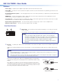
DVI 104 TX/RX • User Guide
The Extron DVI 104 Tx and DVI 104 Rx are fiber optic transmitter and receiver units that extend DVI signals up to 500 meters
(1,640 feet) using four multimode fiber optic cables. Optional four-fiber multimode cables are available in varying lengths.
•
The transmitter plugs directly into the source device and the receiver plugs directly into the display device.
•
The transmitter and receiver pair can handle DVI video signals with resolutions up to 1920 x 1200 or 1080p at 60 Hz.
FCC Class A Notice
This equipment has been tested and found to comply with the limits for a Class A digital device, pursuant to part 15 of the FCC
rules. The Class A limits provide reasonable protection against harmful interference when the equipment is operated in a commercial
environment. This equipment generates, uses, and can radiate radio frequency energy and, if not installed and used in accordance with
the instruction manual, may cause harmful interference to radio communications. Operation of this equipment in a residential area is
likely to cause interference. This interference must be corrected at the expense of the user.
NOTE: This unit was tested with shielded I/O cables on the peripheral devices. Shielded cables must be used to ensure
compliance with FCC emissions limits.
For more information on safety guidelines, regulatory compliances, EMI/EMF compatibility, accessibility, and related topics, see
the “Extron Safety and Regulatory Compliance Guide” on the Extron website.
FDA/IEC 60825-1 Requirements
CLASS 1 LASER PRODUCT
Complies with FDA performance standards for laser products except for deviations pursuant to Laser Notice No. 5, dated June 24,
2007.
The product is intended to be used with the fiber optic cables fully installed.
This product meets the applicable requirements of IEC 60825-1, Edition 1 (2007).
Any service to this product must be carried out by Extron Electronics and its qualified service personnel.
Application Diagram
PC with DVI Output
Hi-resolution
Flat Panel Display
with DVI-D Input
DVI 104
Transmitter
4 Multi Mode
Fiber
Up to 500 meters (1640 feet)
DVI 104
Receiver
1
DVI 104 TX/RX • User Guide
Features
Power supply — Separate power supplies are provided for both the transmitter and receiver.
Power LEDs — The LEDs are on the top and bottom panels of both the receiver and transmitter. They illuminate green when the unit
is receiving power.
No mounting hardware required — The units plug directly into the source device (transmitter) or output device (receiver) and take up
very little space.
EDID Minder — The DVI 104 transmitter is able to capture and store the resolution and refresh rate of the display device, which
ensures that the source boots up with the correct resolution.
Long cable runs — The DVI 104 Tx/Rx uses four fiber optic cables to extend video signals up to 500 meters (1,640 feet). The cables
must be either 62.5/125 multimode cable or 50/125 multimode cable.
High resolution signal transmission — The units transmit signals at resolutions up to 1920 x 1200 or 1080p @ 60 Hz.
High rate of data transfer — The units can transmit signals at up to 1.65 Gbps
Front Panel Features
1
2
a
Power input — The transmitter and receiver both have plugs for a 3.5 mm jack to provide
5 VDC to the unit.
The center pin of the jack carries +5 VDC; the outer shell of the jack is the negative rail.
NOTES:
• If the source device is able to provide 5 VDC on pin 14 of its DVI output, the
transmitter can draw power from the source device. If the source is a laptop or a
PC using a PCI-E graphics card, it will not be able to provide enough power and the
transmitter must be powered with a separate external power supply.
• The receiver must be powered by an external power supply through the power
input plug.
b
LC jacks — Four fiber optic cables connect the transmitter to the receiver. The cables connect to the four female LC jacks in each
of the units.
A label on the top panel identifies the unit as the transmitter or receiver and identifies the fiber optic port numbers and the power
input.
NOTES:
• For the transmitter, port 1 is closest to the power input and port 4 is furthest away. For the receiver, port 4 is closest to
the power input and port 1 is furthest away.
• Although the orientation is reversed, ports with the same number must be connected by the same cable, so that port 1
on the receiver is connected to port 1 on the transmitter, and so forth.
Insert the end of the fiber optic cable into the appropriate plug on the transmitter
or receiver. The locking catch should snap into the slot and hold the cable securely
in place.
If the cable is loose or slips out of the slot easily, move the release catch from its
normal position above the locking catch, to the adjusted position under the locking
catch (see the figure above right). This provides the extra leverage required to keep
the locking catch in place and hold the cable securely.
Locking catch
Release catch
Normal Position
Adjusted Position
2
DVI 104 TX/RX • User Guide
Rear Panel Features
1
3
6
c
8
3
Male Connector
9
17 19
A single-link DVI-D male connector is used to connect the transmitter to the
source and the receiver to the output device.
Pin Signal
22 24
Pin Signal
Pin Signal
1
TMDS data 2-
9
TMDS data 1-
17
TMDS data 0-
2
TMDS data 2+
10
TMDS data 1+
18
TMDS data 0+
3
TMDS data 2
shield
11
TMDS data 1
shield
19
TMDS data 0
shield
6
DDC clock
14
+5 V power
22
TMDS clock shield
7
DDC data
15
Ground (+5V)
23
TMDS clock+
8
CEC control
16
Hot plug detect
24
TMDD clock -
Top Panel Features
4
5
LED — Both the transmitter and receiver have LEDs on the top and bottom
panels that light green when the unit is receiving power. The LEDs on the
transmitter also functions as a status indicator for the EDID minder feature (see
“Setup and Operation” below).
e
Thumbscrews — Use the thumbscrews to secure the transmitter or receiver
to its connector.
f
Label — a label in this space on the top panel identifies
the unit as the transmitter (Tx in the figure at right) or
receiver (Rx) and also identifies the power input (5 VDC)
and the fiber optic port numbers (1, 2, 3, and 4).
6
Extron
33-1641-01
Rev. A 05 08
TO COMPUTER (Tx)
PN 60-977-12
5V
1
2
3
www.extron.com
d
4
Bottom Panel Features
The bottom panels of both the transmitter and receiver have a label that identifies the serial number of the unit. There is also a second
power LED that mirrors the signals given by the LED on the top panel.
Side Panel Features (Transmitter Only)
g
7
EDID Minder storage button (transmitter only) — A recessed switch
activates the transmitter to capture and store EDID information from the display
device. This allows the source device to provide a signal with a resolution
and refresh rate matching the needs of the display device (see “Setup and
Operation” ).
Setup and Operation
When using the DVI 104 Tx/Rx for the first time or if the display device is changed, it is essential to set up the EDID Minder. The
setup process places EDID information on a EEPROM chip in the transmitter, which allows the video source to boot up correctly. This
process is described below in steps 1-6. If you have already set up the EDID Minder, proceed to step 7.
1. Ensure that the source, the display, the transmitter, and the receiver are all powered off and that the fiber optic cables are
unplugged from the transmitter and the receiver.
2. Apply power to the transmitter by inserting the cable from the external power supply into the input jack. The LEDs should
illuminate a solid green.
3
DVI 104 TX/RX • User Guide
3. Press and release the EDID Minder programming button by gently inserting a pointed device, such as a paper clip, into the recess
on the side of the transmitter. The green LED should blink twice and turn off, although power is still connected. The transmitter is
ready to capture EDID information from the display device.
4. Power on the display device.
5. Connect the transmitter directly to the DVI input of the display device. The green LEDs on the transmitter blink rapidly for a few
seconds to indicate that it is reading and storing EDID information from the display device.
When the information has been captured and stored, the green LEDs stop blinking. They may light a solid green or they may turn
off, depending on the display device.
NOTE: The transmitter must remain connected to both the display device and the power supply for the entire time that the
EDID capture is taking place.
6. Once the capture and storage are complete and the green LEDs are no longer blinking, disconnect the transmitter from both the
power and the display device.
NOTES:
• Once the transmitter has captured the EDID information from the display device, the information is stored on an EEPROM
chip in the transmitter. Therefore, this calibration needs to be performed only once, as long as the display device is not
changed.
• If the display device is changed, repeat steps 1-6 to capture and store the EDID information for the new device.
7. Apply power to the receiver by inserting the cable from the external power supply into the input jack. The LEDs should illuminate a
solid green.
8. Ensure that the display device is still powered on, connect the receiver directly to the DVI input, and tighten the thumbscrews.
9. Ensure that the PC or source is powered off, connect the transmitter directly to the DVI input, and tighten the thumbscrews.
10. If required, apply power to the transmitter by inserting the cable from the external power supply into the input jack. The LEDs
should illuminate a steady green.
NOTE: If the PC or source is able to provide 5 VDC on pin 14 of its DVI output, the transmitter can draw power from the
source device. If the source is a laptop or a PC using a PCI-E graphics card, the source device cannot provide enough
power and the transmitter must be powered with a separate external power supply.
11. Connect all four fiber optic cables between the transmitter and receiver. Pay attention to the orientation of the LC connectors and
ensure that each cable joins ports with the same number (port 1 of the transmitter must be connected to port 1 of the receiver,
and so forth).
Extr
on
Extr
on
3
D
PN ISPLA
60-9
Y
77-1 (Rx)
4
3
3
2
1
om
2
33-1
Rev 64201
.A
TO 05 08
5V
tro
n.c
1
4
om
3
tro
n.c
OM
P
60-9UTER
77-1 (Tx)
2
2
1
ww
w.e
x
PN
ww
w.e
x
33-1
Rev 64101
.A
05
08
C
TO
5V
4
12. Turn on the source device. The source device should read the information stored in the transmitter and boot up to that resolution
and refresh rate.
4
DVI 104 TX/RX • User Guide
Troubleshooting
Display does not show an image
•
Ensure that all plugs and jacks used by the external power supplies are firmly
connected.
Locking catch
If the cable is loose or slips out of the slot easily, move the release catch from its
normal position above the locking catch, to the adjusted position under the locking
catch (see the figure at right). This provides the extra leverage required to keep the
locking catch in place and hold the cable securely.
•
Ensure that the green LEDs for both the transmitter and receiver are on.
•
Ensure that the correct EDID information has been stored on the transmitter’s
EDID Minder. When using the DVI 104 Tx/Rx for the first time or if the display
device is changed, it is essential to set up the EDID Minder as described in
steps 1-6 of “Setup and Operation” on page 3 of this guide.
Release catch
Normal Position
Adjusted Position
•
Ensure that the source device and output device are powered on and have booted correctly.
•
Ensure that the fiber optic cables are connecting the correct ports. A port on the transmitter must be connected to the same
numbered port on the receiver. For example,
port 1 of the transmitter must be connected to port 1 of the receiver.
•
Ensure that the fiber optic cable jacks are securely seated.
•
Ensure that the transmitter is firmly plugged into the source device and the receiver is firmly plugged into the output device.
•
Try resetting the system by unplugging and reconnecting the DVI connectors or the power jacks.
•
Try rebooting the computer.
Screen is distorted or displays noise
•
Ensure that the cable length does not exceed 500 meters (1,640 feet).
•
Ensure that the cables are high quality multimode cable and are terminated with securely fitting plugs.
•
Ensure that the graphic resolution is correctly set (see “Setup and Operation”).
•
View the “Display Properties” of the source device to check the output resolution. The resolution and refresh rate must match the
capabilities of the display device and must not exceed 1920 x 1200 at 60 Hz.
•
Try resetting the system by unplugging and reconnecting the DVI connectors or the power jacks.
Extron Headquarters
+800.633.9876 Inside USA/Canada Only
Extron USA - West
Extron USA - East
+1.714.491.1500+1.919.850.1000
+1.714.491.1517 FAX
+1.919.850.1001 FAX
Extron Europe
+800.3987.6673
Inside Europe Only
+31.33.453.4040
+31.33.453.4050 FAX
Extron Asia
+65.6383.4400
+65.6383.4664 FAX
Extron Japan
+81.3.3511.7655
+81.3.3511.7656 FAX
Extron China
+86.21.3760.1568
+86.21.3760.1566 FAX
Extron Middle East
+971.4.299.1800
+971.4.299.1880 FAX
Extron Korea
+82.2.3444.1571
+82.2.3444.1575 FAX
Extron India
1800.3070.3777
(Inside India Only)
+91.80.3055.3777
+91.80.3055.3737 FAX
© 2013 Extron Electronics All rights reserved. All trademarks mentioned are the property of their respective owners. www.extron.com
68-1549-01 Rev. D
12 13