1
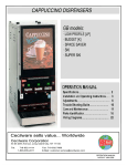
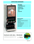
CAPPUCCINO, COFFEE, and SOUP DISPENSERS
GB models:
•SUPER HIGH CAPACITY
•SPACE SAVER
•FEATURE FLAVOR
•STAINLESS STEEL [S/S]
•BUDGET [K]
•SKI
•OCS
•LOW PROFILE [LP]
OPERATION MANUAL
• Specifications................................................. 2
• Installation and Operating Instructions........ 3
• Adjustments................................................... 6
• Trouble Shooting Guide.............................… 10
• Care and Maintenance..................................11
• Parts Identification....................................... 17
• Wiring Diagrams........................................... 20
Cecilware sells value... Worldwide
45 -05 20th Avenue, Long Island City, NY 11105
•
FAX
718-932-1414
718-932-7860
NA33A-C 3/1/2003
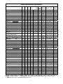
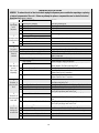
Models and Mechanical Specifications
MODEL:
WIDTH DEPTH HEIGHT
HOPPERS
TANK
BURST LIT DISPLAY AREA SHIPPING
in
in
in
QTY .
LB. GAL. HOT CAPACITY (W x H) Sq. in. WEIGHTLB.
WATER
GB2-LD DELUXE-SUPER HIGH CAPACITY 11
GB3-LD
14 1/8
GB4-LD
17
2
2.75
6
58
133
160
(7 x 13) 91
(9½ x 13 ) 123
(123/8 x 13) 164
90
105
130
8 SQ
4
5½
4
2
2
2.75
3.75
58
58
85
112
(7 x 13) 91
(7 x 13) 91
(9½ x 13) 123
(123/8 x 13) 164
65
72
95
110
2
3
2+1
4
2+2
3 +1
5
4 +1
5½
4
5½ +10 P
5½
5½ +10 P
5½+11 SQ
5½
5½ +10 P
2
2.75
2.75
2.75
6
6
6
6
58
85
112
112
140
140
140
140
(7 x 13) 91
(9½ x 13) 123
(123/8 x 13) 164
(123/8 x 13) 164
(123/8 x 13) 164
(123/8 x 13) 164
(123/8 x 13) 164
(123/8 x 13) 164
86
100
110
120
140
140
140
140
34 ½
5 +1
5+10 P
22
34 ½
7 +1
5+10 P
22
22
22
31 ½
34
34
1
2
3
8 SQ
5½
5½
8½
11
14 1/8
22
22
22
31 ½
31 ½
31 ½
2
3
4
11
GB2M-8-LD
FEATURE FLAVOR
GB2M-8W-LD [w/Hot water]
11
GB3M-8-LD WAS GB4M-8
14 1/8
GB3M-8W-LD [w/Hot water] WAS GB4M-8W 14 1/8
22
22
22
22
31 ½
31 ½
31 ½
31 ½
1K-GB-LD ECONOMY W/MOLDED DOOR
2K-GB-LD
3K-GB-LD
4K-GB-LD
20
20
20
20
22
22
22
34
34
34
8½
8½
11
14 1/8
22
22
22
22
31 ½
31 ½
31 ½
31 ½
1
2
3
4
8½
11
11 ½
14 1/8
17
17
17
17
22
22
22
22
22
22
22
22
34
34
34
34
34
34
34
34
GB6M-10-LD STEEL DOOR
21 ½
GB6M-10-LD MOLDED DOOR
GB8M-10-LD –2T STEEL DOOR (DUAL TANK)
27
GB8M-10-LD –2T MOLDED DOOR (DUAL TANK)
8½
GB1M-LD-S/S
S/S
GB2M-5.5-LD-S/S
8½
GB3M-5.5-LD-S/S
11
22
GB2MW -LD [w/Hot water]
GB3MW -LD [w/Hot water]
GB4MW -LD [w/Hot water]
GB1M-LD
GB2M-LD
GB3M-LD
GB4M-LD
GB2M-5.5-LD
GB3M-5.5-LD
GB3M-10-LD
GB4M-5.5-LD
GB4-LD
GB4M-11-LD
GB5M-5.5-LD
GB5M-10-LD
SPACE SAVER
SPACE SAVER
3K-GB-5.5-LD
SKI
OCS –1-LD
OCS –2-LD
OCS –3-LD
GB2-LP-LD
GB3-LP-LD
GB4-LP-LD
15 5/8
15 5/8
11
5K-GB-LD
GB1SKI -LD
GB2SKI -LD
8½
8½
10
LOW PROFILE
2
10
1+ 2 5 ½ & 10
2+ 2 5 ½ & 10
(187/8 x 135/8) 257
(22½ x 135/8) 307
3.75 x2 (112 x 2) (243/8 x 135/8) 332
224
(28 x 135/8) 382
58
(7 x 13) 91
2
58
(7 x 13) 91
2
85
(9½ x 13) 123
2.75
6
140
4
5½
4
2
2.75
3.75
58
85
112
(7 x 13) 91
(9½ x 13) 123
(123/8 x 13) 164
70
90
110
1+1
1+1
1+ 2
1+ 2
8 SQ + 4
8 SQ + 4
8 SQ + 4
8 SQ + 4
2.75
2.75
3.75
3.75
85
85
112
112
(9½ x 13) 123
(9½ x 13) 123
(123/8 x 13) 164
(123/8 x 13) 164
90
90
110
110
31 ½
31 ½
31 ½
31 ½
1
2
3
4
8 SQ
4
4
4
2
2
2.75
3.75
58
58
58
58
(6½ x 13½) 88
(6½ x 13½) 88
(81/8x13½) 110
(12½x12) 150
64
70
81
120
20
31 ½
5
4
3.75
58
(12½x12) 150
125
22
34
3
5½
2.75
58
(83/4 x13½) 110
110
1
38
38
1
2
14 SQ
14 SQ
2.75
6.5
93
186
(7 x 13) 91
(123/8 x 13) 164
85
115
8 ½ 23 /4
14 1/8 23 1/4
160
+ SKID
195
+ SKID
70
70
100
8½
8½
10
20
20
20
27 ½
27 ½
27 ½
1
2
3
8 SQ
4
4
2
2
2.75
58
58
58
(6½ x 13½) 88
(6½ x 13½) 88
(6½ x 13½) 88
55
70
75
8½
11
141/8
20
20
20
27 ½
27 ½
27 ½
2
3
4
4
4
4
2
2.75
2.75
58
58
58
(6½ x 13½) 88
(6½ x 13½) 88
(93/4 x 12) 117
70
75
100
All models are with or without -LD (Lit Display). Height: Add an additional 1” when installing with 1” feet or 4” when installing with 4”legs.
Plumbing: ¼” water line required.
* Burst Capacities : Max. # of drinks dispensable with available hot water - based on 6 oz. cups.
** Clearance: Add 2" for line cord and valve fitting in the back of unit.
2
Electrical Specifications
Model No.
ALL MODELS
GB3K [NES]
ALL MODELS
ALL EXPORT MODELS
Volts
120V
120V
120/240V
220V
GB3\4
120/240V
GB8M
120 EACH
(2 SEPARATE CIRCUITS)
Number of
Heaters
1
1
1
1
Amps
15
15
15
15
Receptacle
Nema No.
5-15R
5-15R
L14-20R**
††
Circuit
Breaker
15A
15A
20A
20A
30A
15A (2)
Phase
1
1
1
1
Hz
60
60
60
60
Watts
1.8KW
1.8KW
3.0KW
3.0KW
1
1
60
60
6.0KW
2
25
L14-30R**
1.8 KW 1 PER TANK 15 EACH 5-15R (2)
EACH
(2 TANKS)
120V, 1.8 KW, 15A, Nema 5-15R standard on all models; 3.0 KW and 6.0 KW, 120/240V units available
** 120/240V, 3 pole, 4 wire grounding type Twist-Plug Receptacle. For 240V units, Use L6-20R or L6-30R, 2 pole, 3 wire Twist-Plug Receptacle.
†† 220V Export Receptacle to be specified where order is placed.
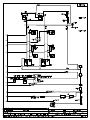
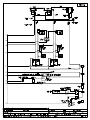
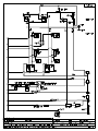
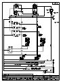
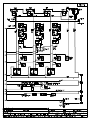
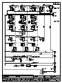
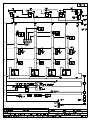
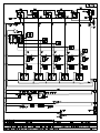
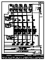
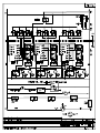
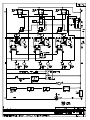
For Wiring, refer to Wiring Diagrams in back of manual. See Electrical Data Label attached to the back of the unit for proper voltages, breaker
sizes and electrical outlet requirements for each model number listed.
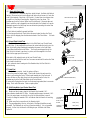
INSTALLATION INSTRUCTIONS
Water Inlet Connection:
This equipment is to be installed to comply with the applicable Federal, State, or local plumbing codes having jurisdiction. In addition:
1. A quick disconnect water connection or enough extra coiled tubing (at least 2x the depth of the unit) so that the machine can be moved for
cleaning underneath.
2. An approved back flow prevention device, such as a double check valve to be installed between the machine and the water supply.
The GB beverage dispenser is equipped with a ¼" Flare Water Inlet Fitting which is located on the left side in the back of the base (when looking at
the machine from the front).
HIGHLY RECOMMENDED:
A WATER SHUT-OFF VALVE and A WATER FILTER, preferably a combination Charcoal/Phosphate Filter, to remove odors and inhibit lime and scale
build up in the machine.
Note: In areas with extremely hard water, a water softener must be installed in order to prevent a malfunctioning of the equipment and in order not
to void the warranty.
After the machine has been unpacked and placed on a counter, pull out the stainless steel drip tray. It should contain the following:
A Set of 4 Adjustable Leveling Legs & Water Inlet Fitting.
START-UP PROCEDURE
Caution: Make sure that the Heater Switch, located behind right hopper with door opened, is in the OFF position.
1.
2.
3.
4.
5.
6.
Connect the ¼" dia. copper waterline to the ¼" flare water inlet fitting of the valve.
Plug the power cord into a proper receptacle.
Activate the Power Switch (Toggle Up). The door display panel, the red power indicator light and the green dispense buttons will light up and
the tank will start filling. Allow approximately 4-5 minutes for the tank to fill.
Activate the Heater Switch. Allow approximately 10-30 minutes for the water to reach a temperature of 195°F. The heat up time will
depend on the water inlet temperature, the input voltage and the wattage of the elements in the machine.
Place a 6 oz. or larger cup under the left dispense nozzle, press and hold the left dispense switch for 6 seconds. The machine will dispense
water at the rate of 1 oz. per second. Repeat it several times to check for consistent output. Repeat same for the other dispense switches.
This procedure checks that the dispense valves are not airlocked.
While the tank is heating up, remove the hoppers, load them with products and reposition them back in the machine. When the green ready
light comes on, the tank has reached its brew temperature and the machine is ready to dispense the first cup of Cappuccino.
To Dispense a Cup of Cappuccino or Coffee or Soup: Place a 8 oz. or larger cup under selected drink dispense nozzle.
For Manual units: Push and hold brew button until cup is 2/3 full, then release button.
For Automatic units: Press and Release button. Cup will fill up automatically to it’s preset amount.
See Drink Strength Adjustments if different levels of drink strength are desired or Programming Dispense Volume if different cup sizes are
used.
3
UNPACKING INSTRUCTIONS
Carefully unpack the GB Machine and inspect immediately for shipping damage. Your GB Machine was shipped
in a carton designed to give it maximum protection in normal handling. It was thoroughly inspected before
leaving the factory. In case of damage, contact the shipper, not Cecilware.
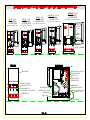
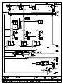
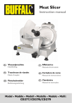
DESCRIPTION AND LOCATION OF COMPONENTS
Note:
Refer to Illustration A for description and location of COMPONENTS and CONTROLS.
1.
HOPPERS. Depress the door latch on the left side of the door and pull door open to access the hoppers.
The hoppers hold up to 14 lbs. of Cappuccino product and up to 1.5 lbs. of freeze dried coffee product , depending on model number (see
spec. sheet).
To remove the hoppers simply swing the top compartment door open and lift out the hoppers.
To reposition the hoppers in the compartment, slide the hopper base back between the rails until the ¼" pin at the bottom of the hopper base
falls into the ¼" positioning hole of the compartment base cover.
2.
RINSE SWITCH. With the door open, the rinse switch is located on the left side the first Whipper chamber.
In the RINSE position it disengages the hopper motors and allows only water to be dispensed.
It is used for flushing out the Whipper chambers and to adjust the water dispense valves for proper flow rates.
3.
HEATER SWITCH. This switch is located inside the cabinet behind the right hopper, open door and remove right hopper to access
it. Its primary function is to shut off the heating element during the initial priming, start up operation of the machine, or whenever the tank is
being drained for service.
Note: On 120V, 1.8 KW and 120/240V, 3 KW machines, the Power Switch and Heater Switch must be ON in
order for the elements to operate.
4. POWER SWITCH. This switch is located on the left side of the splash panel below the door. On 120V, 1.8 KW and 120/240 or 240V, 3 KW
single element machines the power switch controls all power to the machine including the heater elements.
Note: On 120/240V, 6 KW machines , the Power and Heater Switches are independent of each other. Both switches must be OFF
in order for the machine to be completely shut down.
5.
WATER LEVEL CONTROLS:
Under normal conditions and operation, the water level in the tank should not drop more than ½" from the probe. If it does, the tank is not
refilling fast enough. Check the water line and water filter, they may need cleaning or replacing.
1. Solid state water level control board
2. Water inlet valve
3. Water level probe
4. Hi-level float switch
Part# L398A
Part# L462A
Part# K402Q [K402A & P410A]
Part# L499A [was L380A]
4
OCS2 - 4 lb.
FRONT VIEW
w/ OPEN DOOR
GB2LP - 4 lb.
FRONT VIEW
w/ OPEN DOOR
(8.5"W x 20"D x 29"H)
(8.5"W x 20"D x 29"H)
GB2M - 4 lb.
FRONT VIEW
w/OPEN DOOR
GB2M5.5 - 5.5 lb.
FRONT VIEW
w/OPEN DOOR
GB2SKI - 14 lb
FRONT VIEW
w/ OPEN DOOR
(14 1/8"W x 23 1/4"D x 38"H)
(8.5"W x 22"D x 31.5"H)
(8.5"W x 22"D x 31.5"H)
14 LB
LAMP
SOCKET
14 LB
5.5 5.5
LB LB
LAMP
4 LB 4 LB
4 LB 4 LB
4 LB 4 LB
PRODUCT
GUIDE
LAMP
STARTER
CORD SET
WHIP CHAMBER
DRIP TRAY
DRIP TRAY
DRIP TRAY
DRIP TRAY
DRIP TRAY
HI-LIMIT (TEMP)
LABEL AREA
WATER LEVEL CONTROL
DISPENSE VALVE
TANK ASS'Y
HEATER ASS'Y
AUGER MOTOR
PRODUCT LABEL
DISPENSE BUTTON
POWER SWITCH
PILOT LIGHT FOR HEATER
RINSE SWITCH
THERMOSTAT
WHIPPER MOTOR
BLOWER DUCT HOSE
FAN/BLOWER
DRAIN HOSE W/PLUG
WATER INLET VALVE
POWER CORD
DRIP TRAY
DRIP TRAY
RELAY/TIMER
5
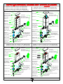
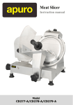
The Dispense Valves are factory adjusted for a maximum Flow Rate of 1 to 1.3 oz./sec .
Approximate settings:
0.85 to 1 oz./sec for SOUP ; 1.3 oz./sec. for COFFEE and CAPPUCCINO ]
Exceeding this Flow Rate will cause the Mixing Chamber to overflow.
Note: To access the Water Dispense Valves, open door and remove Hoppers.
To reduce Flow Rate turn CW with screwdriver 1/4 turn at a time.
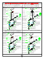
WATER FLOW ADJUSTMENT
AUGER GEAR R ectangular Hoppers:
CD117 [w/NYLON AUGER CD130]
CD117 [w/WIRE AUGER CD101 & CD149]
CD97A [w/WIRE AUGER CD74A & CD153]
CD320 [w/WIRE AUGER CD74A f/Coffee]
DISPENSE VALVE
L467A
CD130 NYLON AUGER [22.5mm Ø X 17mmPT]
W/O-RING CD139
CD101 WIRE AUGER [22.5mm Ø X 17mmPT]
CAPPUCCINO/FAST FLOW & SOUP
CD149 WIRE AUGER {22.5mm Ø X 24.8mmPT]
HOT CHOCOLATE & THICK SOUP
CD74A WIRE AUGER {17mm Ø X 12mmPT]
DRY COFFEE/FAST FLOW
FRONT BUSHING
Rectangle Hoppers :
CD277 [22.5mm Ø]
CD306 [17mm Ø]
NUT CD136
TURN TO UNSCREW
Square Hoppers :
CD102 [22.5mm Ø W/ O-RING CD103]
CD131 [17mm Ø W/ O-RING]
or
CD76A
AUGERS:
Z:\DRAWINGS\NA000\NA33A-C-GB-MAN.dwg, 02/28/2002 11:07:19 AM, 1:1
CD153 WIRE AUGER [17mm Ø X 9.15mmPT]
DRY COFFEE & INSTANT ESPRESSO
A. When using NYLON AUGERS :
Adjust Water Flow Rate so that
the water level reaches almost
at the top in the Mixing Chamber,
as shown.
SPLASH GUARD
CD115
CD90A
PRODUCT
GUIDE
CD70A
DISPENSE CAP
CD61A white
CD272 black
DISPENSE CAP
CD61A white
CD272 black
RECTANGULAR RIB
B. When using WIRE AUGERS:
Adjust Water Flow Rate so that
the water level reaches half
way up in the Mixing Chamber,
as shown.
TRIANGULAR RIB
CORRECT WATER LEVEL FOR MAX
FLOW RATE WHEN USING WIRE
AUGER.
TRIANGULAR RIB
CORRECT WATER LEVEL FOR MAX
FLOW RATE WHEN USING NYLON
AUGER.
MIXING CHAMBER FAST FLOW
CD145-white
COLD UNITS
MIXING CHAMBER FAST FLOW [HOT]
CD137 white / CD275 black
GB UNITS
6
MIXING CHAMBER
CD62A-white / CD274-black
SOUP UNITS
THERMOSTAT ADJUSTMENTS
(L029A) THERMOSTAT
120/240V, 3 KW & 6 KW
USED ON GBs
Adjustment Screw
Pilot Load
L253A THERMOSTAT
120V, 1.8 KW (WAS L266L)
USED ON GBs
Locate Thermostat: Remove the right side panel. Thermostat is mounted on side
of tank.
The GB beverage dispensers are factory set to deliver hot brewing water at 195°F
with the thermostat knob turned to full ON position. If adjustments should be
necessary to increase or decrease the water TEMPERATURE, proceed as follows:
Note: Set the Rinse Switch to ON. This will disengage the Hopper Motors
when dispensing water for Temperature measurements.
1. To INCREASE the water temperature - With the Thermostat Knob to its
maximum clockwise position, remove the knob and locate the slotted adjustment
screw inside the hollow thermostat shaft. Using a narrow-bladed screwdriver,
engage slotted adjustment screw and turn it ¼ turn slowly counter-clockwise.
Allow a few minutes for the temperature to reach set level. The Heater Light will go
ON, indicating the heating element is activated, wait for it to go OFF, indicating that
the water has reached new set temperature. Take a temperature reading and repeat
if necessary.
2. To DECREASE the water temperature - simply turn the Thermostat Knob one
notch counter-clockwise to the next lower dial setting.
INSTRUCTIONS FOR ADJUSTING SPEED CONTROL L556A WITH DC MOTOR CD151
ADJUSTMENT INSTRUCTIONS FOR SPEED CONTROL
L556A WHEN USED WITH DC MOTOR CD151:
1. SET SPEEDPOT KNOB AT # 5
2. PRESET TRIMPOT AS SHOWN IN THE
ILLUSTRATION, POINTING TO 5 O'CLOCK
3. APPLY POWER AND ROTATE TRIMPOT UNTIL
THE MOTOR TURNS 55 RPM (15V DC)
7
EDDRINK STRENGTH ADJUSTMENTS - by adjusting the Auger Speed.
I. UNITS WITH FIXED SPEED AUGER MOTORS-AC [CD150] - Fixed Auger Speed [95 RPM] and dispenses powder at a constant fixed rate.
Drink Strength adjustments can be made by adjusting the water flow rate on the Water Dispense Valves . [See ILL. C]
1. Remove Hoppers to access the Dispense Valve, located behind the hoppers.
2. Locate Flow Adjustment Screw on Dispense Valve. ( See illustration C)
3. Rotate adjustment screw Counterclockwise to INCREASE Flow Rate, Clockwise to DECREASE Flow Rate.
(Note: the water flow rate should not exceed 1 to 1.3 oz./sec.)
Do not turn Adjustment Key more than 1/4 turn at a time without checking drink strength (ratio of water to powder).
II. UNITS WITH VARIABLE SPEED AUGER MOTORS-DC [CD151] - Variable Auger Speed [10 to 130 RPM]
Drink or Product Strength adjustments can be made by adjusting the Auger Motor RPM [knob on inside door panel],
which controls the amount of product being dispensed [gram throw]. The gram throw is factory preset at 7.
Because the consistency of each product varies, the customer can set the desired gram throw for each hopper.
The water flow rate on the Dispense Valves should remain fixed.
Note: the water flow rate should not exceed 1-1.3 oz./sec to avoid spillage from dispense chamber. [See ILL. C]
DRINK SIZE ADJUSTMENTS
a. Manual Machines : Hold down the Dispense Button until desired amount is dispensed.
b. Automatic Machines with Timer L493A on Inside Door Panel NOT Programmable] & speed control
board L556A : To increase the volume, turn the dial to the next increment. [0-1 is equivalent to 2 sec.]
c. Automatic Machines with Programmable "Teach me"Timers [L576A or L582A]: These units do not
have a cup size adjustment knob inside the door, since the timer is programmable from the dispense button.
Z:\DRAWINGS\NA000\NA33A-C-pages\NA33A-C-GB-MAN.dwg, 04/05/2002 01:06:07 PM, 1:1
PROGRAMMING FOR AUTOMATIC DISPENSE
1. Turn Power Switch ON (toggle switch inside door).
2. PRESS and HOLD [red] STOP Button with one hand.
3. PRESS and HOLD [green] DISPENSE Button with other hand.
4. RELEASE [red] STOP Button ONLY.
5. Continue to HOLD [green] DISPENSE Button for 5 SECONDS, then RELEASE.
6. PRESS and RELEASE [green] DISPENSE Button. Product begins dispensing.
When it reaches the "DESIRED VOLUME",
7. PRESS and RELEASE [green] DISPENSE Button to SET "DESIRED VOLUME".
DISPENSE Button can be "jogged" to top off.
8. PRESS and RELEASE [red] STOP button to LOCK IN "DESIRED VOLUME".
Repeat steps 1 to 8 for each Dispense Button.
PROGRAMMING INSTRUCTIONS FOR MANUAL DISPENSE
1. PRESS AND HOLD STOP [red] BUTTON WITH ONE HAND.
2. PRESS AND HOLD DISPENSE [green] BUTTON WITH OTHER HAND.
3. RELEASE STOP [red] BUTTON.
4. CONTINUE TO HOLD [green] DISPENSE BUTTON FOR 5 SECONDS.
5. RELEASE DISPENSE [green] BUTTON.
6. PRESS AND RELEASE STOP [red] BUTTON.
The Total Time The Water Is Running Is Accumulated And Saved Into Memory. For Normal Operation,
Press and Release Dispense Button.
The Timers Have Been Factory Preset for 6 oz. Cups for Coffee; For 8 oz. Cups for Soup and Cappuccino.
To Change To Larger Or Smaller Cup Sizes [Volumes] Repeat Steps 1 To 8 Above.
TO CHECK VOLUME AND GRAM THROW DISPENSED (ratio):
1. Remove the product guide from the hopper and position a receptacle under the hopper nozzle to catch the gram throw of product.
Also place a measuring cup under extension tube to catch the water dispensed.
2. Push the dispense button and check the amount of product dispensed, amount of water dispensed, and time [use stop watch] to dispense that water.
3. The amount of of water dispensed in the measuring cup divided by the amount of time to dispense that water is the Water Flow Rate from Dispense Valve.
FOR CAPPUCCINO: The machine is factory adjusted to dispense 4-4.5 gr./sec. per OZ. Cup. [32 grams Product per 8 oz. cup]
The recommended throw is 28-32 grams per 8 oz. cup for Cappuccino, with 80 % fill.
FOR COFFEE: The machine is factory adjusted to dispense 0.3 gr./sec per OZ. Cup. [1.5 grams of coffee product per 5 oz. of liquid (in a 6 oz. cup).
The recommended throw is 1.5 to 1.8 grams per 6 oz. cup of Coffee, with 80 % fill.
FOR SOUP: The machine is factory preset to specified customer requirements, because the gram throw for each soup flavor and type varies
considerably with the consistency of each product. Adjustments can be made by the customer, as shown above.
For customer specified/special settings see inserts I, II, III, etc.
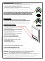
A) Water Inlet Valve Test
Turn power off. If the water level rises inside the tank, the Water Inlet Valve is
leaking. Disconnect wires from the Water Inlet Valve coil and connect a 2 wire line
cord to the terminals. Plug it into a 115V outlet. If water flows in and stops when
you pull it out, the Valve is working fine. Repeat this test a few times. The
problem may be in the Probe or Water Level Control Board. If the water does not
flow in when the cord is plugged into an electrical outlet, the Solenoid coil may be
damaged, opened or the valve may have an obstruction preventing the water from
flowing in. Clean or replace it.
CHECK VALVE ASSY L463A
HOSE NUT ASSY K491A
(was K178A)
A Check Valve is installed to prevent backflow.
To check proper function of Check Valve, disconnect water line from the Check
Valve, check for dripping from the disconnected end of the Check Valve. If it leaks
replace it.
WATER INLET VALVE (.5 gpm)
CD257 110 V, CD258 220 V
was L462A
B) Hi-Level Float Switch Test
The Float Switch acts as a guardian for the Solid State Level Control Board
and its Probe. If they malfunction and cause the water inside the tank to rise, the
Float Switch will prevent flooding by terminating the power to the Solid State
Control Board and the Water Inlet Valve. The correct mounting position of the
Float Switch in the tank is as shown in picture, with the magnets in the Float
Switch in the upper part of the switch.
FLOAT SWITCH
(70 V.A) L499A
After tank is full, unplug the wire to the Level Control Probe,
the water should run into the tank for a few more seconds until it reaches the Float
Switch and it should stop.
If not, and water starts coming out of the Breather tube, the Float Switch is
malfunctioning.
C) Probe Test
If lack of water persists, check the probe as follows:
Turn on the power and water supply. Check inside the tank to make sure the
water is not touching the Probe. Pull wire and terminal out of the Probe rod. If
water still does not flow after the wire is disconnected from the Probe, the
problem may be in the Solid State Water Level Control Board.
If water starts flowing into the tank, the Probe may be grounded, due to excessive
liming. Check with Ohm meter. Clean or replace probe.
D) Solid State Water Level Control Board Test
Check the Board as follows:
1. Make sure there is power input to the Board at the terminals 2 & 3
Your voltmeter should read 115 Volts. It should read the same at terminals 1 & 3.
This is the output power to electrify the coil of the Solenoid Valve to open it.
The lack of voltage at terminals 2 & 4 will indicate that the Board is not working
properly.
2. Make sure all wire connections to the Board are tight.
3. The grounding plate at the top, in the back of the board should be securely
grounded. The Board will not work or will work erratically, if it is not grounded
properly. If after this, the Board is still failing to open the Water Inlet Valve,
replace it.
CORRECT POSITION OF MAGNETS
LEVEL CONTROL PROBE K402Q
TO SOLENOID
N L1
TO PROBE
GROUNDING
PLATE IN
BACK OF THE
BOARD
GROUND
TERMINAL
4 3
2
1
T5
L398C [120V]
L399C [240V]
SS WATER LEVEL CONTROL CCA
TROUBLESHOOTING GUIDE
WARNING: To reduce the risk of electrical shock unplug the dispenser power cord before repairing or replacing
any internal components of the unit.. Before any attempt to replace a component be sure to check all electrical
connections for proper contact.
PROBLEM
1
Light Display
not lit.
No power.
A
B
C
D
E
PROBABLE CAUSE
Dispensing unit unplugged
No power from Terminal Block
Defective Bulb
Defective Ballast.
Loose Bulb in socket.
2
No water when
Rinse Switch is
ON.
A Water supply OFF.
B Clogged inlet screen (Water Inlet Valve).
C Inoperative Water Inlet Valve.
3
No product
when Dispense
Button is
pressed
A
B
C
D
REMEDY
Reconnect dispensing unit
Check the Terminal Block for loose wire
Replace Bulb.
Replace Ballast.
Make sure bulb is seated properly in socket.
Turn water ON.
Disconnect water line and clean inlet screen.
Check connection, if needed replace Valve.
Check all electrical connections.
D Loose electrical connection.
No product in Hopper.
Auger not working.
Damaged, loose, or missing Agitator Gear.
Inoperative Auger Motor or Relay.
E Hopper outlet clogged
F Faulty Coupling.
4
Water does not
shut off.
Water keeps
dispensing.
A Leaking Water Inlet Valve.
B Inoperative Dispense Switch
C Inoperative Rinse Switch
D Clogged/stuck Water Dispense Valve
5
No water is
going into tank
at all.
A Water Inlet Valve malfunction.
B Hi-Level Float Switch malfunction.
C Probe malfunction.
D Solid State Water Level Controls malfunction.
A Water Level Probe malfunction.
6
Water will not B Solenoid (Water Inlet Valve) malfunction.
stop flowing into
water tank.
C Solid State Water Level Control malfunction
7
Water is not
heating up in
the water tank.
A
B
C
D
E
Heater Switch is OFF.
Thermostat is OFF.
Loose connection on Thermostat.
Hi-Limit Temperature Switch is defective
Heater is burned out or defective.
10
Add product.
Engage Hopper/Nut to Motor Gear (See ill. B).
Replace Agitator Gear (See ill. B).
Check connections of Motor, Relay and/or Switch, if needed
replace components.
Clean Hopper and check Cartridge Heater.
Replace damaged Coupling components.
Clean/check fittings of Water Inlet Valve. Replace Water Inlet
Valve if needed. See ”Water Inlet Valve Test”
Check Switch connections. Replace Dispense Switch if needed.
Check Rinse Switch connections.
Replace Rinse Switch if inoperative.
Clean or unclog Water Dispense Valve.
Replace Dispense Valve if inoperative.
Check Solenoid. Replace if necessary.
See “Water Inlet Valve Test”.
Test High-Level Float Switch. See “High-Level Float Switch Test”.
Check Probe. Replace if necessary. See “Probe Test”
Check Water Level Controls. Replace if necessary.
See “Solid State Water Level Control Test”
Check Probe. Replace if necessary. See “Probe Test”.
Check Solenoid. Replace if necessary. See “Water Inlet Valve
Test”.
Check The Water Level Controls. Replace if necessary.
See “Solid State Water Level Control Test”.
Turn Heater Switch ON.
Turn Thermostat ON. (See ill. C) Turn Knob Clockwise.
Make sure all wires and terminals on Thermostat are tight.
Replace the Hi-limit.
Replace the Heater.
SANITIZING:
All sanitizing agents in the food zone must comply with 21 CFR 178.1010.
All food dispensing units should be sanitized periodically. All parts to be sanitized must be cleaned first.
To prepare a sanitizing solution:
ADD 2 TSP. OF LIQUID CLOROX BLEACH (5.25% CONCENTRATION) TO 1 GALLON OF WATER AT ROOM
TEMPERATURE (70°- 90°F).
Note: Always start with a unopened bottle of Clorox Bleach since the solution from an opened bottle has a short life span.
• Soak all parts for a minimum of 3 min. in the sanitizing solution.
• Let all sanitized parts drain and dry naturally. DO NOT WIPE THEM DRY.
• Before using the sanitized unit (or parts) with food stuffs, rinse all parts thoroughly with water.
Water pipe connecting and fixtures directly connected to a potable water supply shall be sized, installed, and maintained in accordance
with Federal, Sate, and Local codes (section 7).
Cleaning
1. Turn the power switch to OFF.
2. Remove the drip tray with grill and empty the contents.
3. Wash and let dry the tray and grill (use a mild dishwasher detergent).
4. Wash and let dry the dispense area.
5. Turn the power switch to ON.
Cleaning the Hoppers (See Hopper Illustration)
1. Open the cabinet door and raise the top cabinet lid.
2. Take the hopper out of the cabinet.
3. Pull off the elbow chute and remove the hopper cover.
4. Unscrew the auger gear CW while holding steady the auger inside the hopper. Take out the auger, agitator wheel, and pring.
5. Rinse each item thoroughly.
6. Let dry all items and reassemble.
Filling the Hoppers
1. Open the cabinet door, raise the top cabinet lid.
2. Fill each hopper with the correct product. Note: Hoppers can also be removed for filling.
3. Reposition hoppers in the hopper compartment, making sure the hoppers are properly seated.
Flushing the Whipper Chamber
1. Open the cabinet door and turn the RINSE switch to ON.
2. Place a container under each dispense nozzle and push the dispense switches.
Note: On manual dispense machines, push and hold the dispense buttons for 10 seconds.
3. Open the cabinet door and turn the Rinse switch back to OFF.
4. Wash and let dry the splash panel.
5. Remove the drip tray, wash and let dry thoroughly.
Removing and Cleaning the Cappuccino Whipper Chambers (See Hopper Illustration)
1. Remove the dispense cap by pulling it forward and at the same time twisting it clockwise.
2. Grab and pull the mixing bowl out of the mixing bowl socket.
3. Grab and twist the whipping chamber clockwise and pull it off the mounting plate.
4. Pull the Whipper blade off the motor shaft. Notice the flat keyway on the shaft and the matching keyway inside the Whipper blade shaft.
It is important that these two keyways are lined up when re-assembling the components.
5. Twist the mounting plate clockwise and pull it off the motor shaft.
6. Slip off the o-ring from the Whipper chamber mounting plate and clean o-ring and o-ring seat.
Removing and Cleaning the Coffee/Tea Mixing Chambers (See Hopper Illustration)
1. Remove the dispense cap.
2. Pull the mixing bowl out of the mixing bowl socket.
3. Take out the extension tubes.
4. Rinse them thoroughly
11
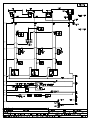
LIT DISPLAY AND STARTER REPLACEMENT ILL. E
To replace the
fluorescent bulb:
Remove the upper inside door
panel. Turn the lamp and pull it
out of the lamp holder, then
place the new lamp into the
lamp holder and turn it until it
snaps into position.
To replace the starter:
Remove the upper inside door
panel, turn the starter slightly
counter-clockwise and take it
out of the starter base.
To install the new starter, snap
the starter into the starter base
and turn it slightly clockwise
into position.
BULB TYPE
F8T5/CW
STARTER TYPE
FS-5
LAMP HOLDER
PRODUCT LABEL
CORD SET
CORD SET
STARTER BASE
BULB TYPE F8T5/CW
WINDOW LABEL
LAMP HOLDER
STARTER TYPE FS-5
SWITCH PANEL
LABEL
STARTER BASE
STOP BUTTON [red]
DOOR FRAME
DISPENSE SWITCH
BREW SWITCH
PRODUCT LABEL
SWITCH PANEL LABEL
DOOR PANEL
DOOR ASSEMBLY (GB3K SHOWN)
(ALL GBKs)
DOOR ASSEMBLY (GB3 SHOWN)
(ALL OTHER GBs)
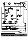
RECOMMENDED PREVENTIVE MAINTENANCE ILL. F
1) CHECK ALL CHAMBER MOUNTS FOR SIGNS OF WEAR
A. Product Running Down The Front Of The Unit.
B. Product Built Up On The Back Of Chamber Mount.
Remove Chamber Mount.
Clean And Re-Lubricate Motor Shaft
Using Food Grade Lubricant Only
Replace With New Chamber Mount.
WATER FLOW ADJUSTMENT
2) CHECK ALL DISPENSE VALVES FOR LIME BUILD-UP.
Drain The Water Tank To Just Below The Level Of The Dispense Valves.
Remove The Valves And Clean. ( You Can Take These Valves Apart
By Hand As Shown).
Replace The Assembly As Needed (L467A).
Replace The Valve Into The Tank And Refill tank.
3) CLEAN OUT VENT MOTOR,
TROUGH AND TUBING.
Lift up black tabs, remove Trough Drawer,
Clean, and replace Trough Drawer.
Remove Hose Assembly From The Motor.
Clean Out And Replace.
HOPPER ASS'Y CD104, 7 LB, 18"HIGHT x 3"W, W/NYLON AUGER
HOPPER ASS'Y CD120, 5.5 LB, 14"HIGHT x 3"W, W/NYLON AUGER
HOPPER ASS'Y CD68A, 4 LB, 11.5"HIGHT x 3"W, W/NYLON AUGER
HOPPER ASS'Y CD313, 1 LB COFFEE, 7.875" HIGHT x 3"W, W/NYLON AUGER
HOPPER ASS'Y CD105 (14 lb; 18"H IGHT X 6.25"SQ) W/NYLON AUGER
HOPPER ASS'Y CD99A (8 lb; 11.5"]HIGHT X 6.25"SQ) W/NYLON AUGER
HOPPER COVER CD106
COVER CD160
AGITATOR GEAR CD117
Agitator Gear with wire CD256
Agitator Gear with spring CD182
AGITATOR CD141
AUGER MOTOR
CD175 90rpm AC
CD87A 44rpm AC (COFFEE)
CD151 90rpm DC (Portion Control)
AGITATOR WIRE
HOPPER CD104
HOPPER CD105
AUGER MOTOR
CD175 90rpm AC
CD87A 44rpm AC (COFFEE)
CD151 90rpm DC (Portion Control)
HOPPER CD99A
HOPPER CD120
HOPPER CD68A
AUGER BUSHING FRONT CD102
WITH 0-RING CD103
HOPPER CD313
AUGER BUSHING FRONT CD277
NUT [2] CD278
FLANGE/ NUT CD271
NYLON AUGER CD130
(22.5 Øx18mmPT)
W/"O" RING CD139
AUGER BUSHING-BACK CD279
MIX BOWL SOCKET CD67A
CD67A W/O-RING M378A
CD100 W/O-RING M480A
BASE MOUNT GROMMET CD66A
SLINGER DISC CD124
DISPENSE CUP
CD61A-white / CD272-black
MIXING CHAMBER
CD137-white / CD275 black
EXTENSION TUBE
M467A - white
H306A-stainless steel
TWIST TO REMOVE
MOUNTING BASE CD65A-white / CD317-black
M379A 'O'-RING #125
WHIPPER BLADE CD64A
HOPPER ASS'Y CD338, 5 LB, 14"HIGHT x 2.5"W, W/NYLON AUGER
HOPPER ASS'Y CD339, 4 LB, 12.5"HIGHT x 2.5"W, W/NYLON AUGER
AUGER MOTOR
CD175 90rpm AC
CD87A 44rpm AC (COFFEE)
CD151 90rpm DC (Portion Control)
Z:\DRAWINGS\NA000\NA33A-C-GB-MAN.dwg, 02/28/2002 11:34:57 AM, 1:1
HOPPER CD338
WHIP CHAM. CD63A
EXTENSION TUBE M467A
EXTENSION TUBE
M467A - white
H306A-stainless steel
SLINGER DISC CD124
TWIST TO REMOVE
MOUNTING BASE CD65A-white / CD317-black
M379A 'O'-RING #125
WHIPPER BLADE CD143 or CD64A
P - HOPPER ASS'Y CD308 LT & CD309 RT 10 LB, 14"H, W/NYLON AUGER
P - HOPPER ASS'Y CD177 LT & CD178 RT 8 LB, 11.5"H, W/NYLON AUGER
AGITATOR GEAR CD117
Agitator Gear with wire CD256
Agitator Gear with spring CD182
AUGER MOTOR
CD175 90rpm AC
CD87A 44rpm AC (COFFEE)
CD151 90rpm DC (Portion Control)
HOPPER CD177 Left shown
NUT [2] CD278
AUGER BUSHING-FRONT CD277
MIXING CHAM. CD137
WHIPPER CHAMBER
CD63A-white / CD316-black
MIX BOWL SOCKET CD67A
CD67A W/O-RING M378A
CD100 W/O-RING M480A
BASE MOUNT GROMMET CD66A
HOPPER CD308 L eft shown
HOPPER CD339
DISPENSE CUP CD61A
MIXING CHAMBER
CD137-white / CD275 black
AGITATOR WIRE
AGITATOR WIRE
NYLON AUGER CD130
(22.5 Øx18mmPT)
W/"O" RING CD139
PRODUCT GUIDE CD70A
DISPENSE CUP
CD61A-white / CD272-black
HOPPER COVER
HOPPER COVER CD187
AGITATOR GEAR CD117
Agitator Gear with wire CD256
Agitator Gear with spring CD182
AUGER BUSHING-BACK CD279
PRODUCT GUIDE CD70A
PRODUCT GUIDE CD70A
WHIPPER CHAMBER
CD63A-white / CD316-black
NYLON AUGER CD130
(22.5 Øx18mmPT)
W/"O" RING CD139
NUT [2] CD278
FLANGE/ NUT CD271
FLANGE/ NUT CD271
AUGER BUSHING-BACK CD279
MIX BOWL SOCKET CD67A
CD67A W/O-RING M378A
CD100 W/O-RING M480A
BASE MOUNT GROMMET CD66A
SLINGER DISC CD124
TWIST TO REMOVE
MOUNTING BASE CD65A
M379A 'O'-RING #125
WHIPPER BLADE CD64A
AUGER BUSHING FRONT CD277
NYLON AUGER CD130
(22.5 Øx18mmPT)
W/"O" RING CD139
NUT [2] CD278
FLANGE/ NUT CD271
AUGER BUSHING-BACK CD279
PRODUCT GUIDE CD70A
DISPENSE CUP
CD61A-white / CD272-black
MIXING CHAMBER
CD137-white / CD275 black
WHIPPER CHAMBER
CD63A-white / CD316-black
EXTENSION TUBE
M467A - white
H306A-stainless steel
MIX BOWL SOCKET CD67A
CD67A W/O-RING M378A
CD100 W/O-RING M480A
BASE MOUNT GROMMET CD66A
SLINGER DISC CD124
TWIST TO REMOVE
MOUNTING BASE CD65A-white / CD317-black
M379A 'O'-RING #125
WHIPPER BLADE CD64A
HOPPER ASS'Y CD144, 5.5 LB, 14"Hx 3"W, W/WIRE AUGER CD101
HOPPER ASS'Y CD152, 4 LB, 11.5"H x 3"W, W/WIRE AUGER CD101
HOPPER ASS'Y CD98A, 4 LB, 11.5"H x 3"W, W/WIRE AUGER CD74A or CD153
HOPPER COVER CD106
HOPPER CD152
AGITATOR CD141
COVER CD160
AGITATOR GEAR
CD117 [W/CD101]
CD97A [W/ CD153A or CD74A]
CD320 [coffee W/ CD74A]
AGITATOR WIRE
HOPPER CD144
HOPPER ASS'Y CD163 (14 lb; 18"H IGHT X 6.25"SQ) W/WIRE AUGER
HOPPER ASS'Y CD162 (11 lb; 14"HIGHT X 6.25"SQ) W/WIRE AUGER
HOPPER ASS'Y CD161 (8 lb; 11.5"]HIGHT X 6.25"SQ) W/WIRE AUGER
HOPPER CD163
DC MOTOR CD151 90rpm
(Portion Control)
DC MOTOR CD151 90rpm
(Portion Control)
HOPPER CD162
HOPPER CD161
HOPPER CD98A
AUGER BUSHING-FRONT CD277
CD306 [W/CD74 & CD153]
NUT [2] CD278
WIRE AUGER
CD101 (22.5 Øx18mmPT)
CD74A (17 Øx12mmPT)
CD153 (17 Øx9mmPT)
FLANGE/ NUT CD271
AUGER BUSHING-BACK CD279
AUGER BUSHING-FRONT CD102
W/"O" RING CD103
MIX BOWL SOCKET CD67A
CD67A W/O-RING M378A
CD100 W/O-RING M480A
BASE MOUNT GROMMET CD66A
DISPENSE CUP CD61A
MIXING CHAM. CD137
SLINGER DISC CD124
MOUNTING BASE CD65A
M379A 'O'-RING #125
WHIP CHAM. CD63A
MOTOR CD151 DC 90rpm
(Portion Control)
Z:\DRAWINGS\NA000\NA33A-C-GB-MAN.dwg, 02/28/2002 11:35:34 AM, 1:1
AGITATOR GEAR
CD117 [W/ CD101]
CD97 [W/ CD153 OR CD74A]
CD320 [coffee W/ CD74A]
MOTOR CD151 DC 90rpm
(Portion Control)
HOPPER CD179 Left shown
NUT [2] CD278
AUGER BUSHING-FRONT CD277
FLANGE/ NUT CD271
WIRE AUGER CD101
(22.5 Øx18mmPT)
AUGER BUSHING-BACK CD279
PRODUCT GUIDE CD70A
DISPENSE CUP CD61A
MIX BOWL SOCKET CD67A
CD67A W/O-RING M378A
CD100 W/O-RING M480A
BASE MOUNT GROMMET CD66A
SLINGER DISC CD124
TWIST TO REMOVE
MOUNTING BASE CD65A
EXTENSION TUBE M467A
MOUNTING BASE CD65A
M379A 'O'-RING #125
P - HOPPER ASS'Y CD179 (LEFT) CD180 (RIGHT) 10 LB, 14"HIGHT, W/WIRE AUGER
AGITATOR WIRE
HOPPER CD155
WHIP CHAM. CD63A
TWIST TO REMOVE
HOPPER COVER
HOPPER CD185
MIXING CHAM. CD137
BASE MOUNT GROMMET CD66A
SLINGER DISC CD124
WHIPPER BLADE CD143 or CD64A
WHIPPER BLADE CD143 or CD64A
HOPPER COVER CD187
AGITATOR WIRE
MIX BOWL SOCKET CD67A
CD67A W/O-RING M378A
CD100 W/O-RING M480A
MIXING CHAM. CD137
EXTENSION TUBE M467A
HOPPER ASS'Y CD185, 4.5 LB, 14"HIGHT x 2.5"W, W/WIRE AUGER
HOPPER ASS'Y CD155, 4 LB, 12.5"HIGHT x 2.5"W, W/WIRE AUGER
AGITATOR GEAR
CD117 [W/ CD101]
CD97 [W/ CD153 OR CD74A]
CD320 [coffee W/ CD74A]
AUGER BUSHING-BACK CD279
DISPENSE CUP CD61A
TWIST TO REMOVE
EXTENSION TUBE M467A
FLANGE/ NUT CD271
WIRE AUGER
CD101 (22.5 Øx18mmPT)
CD74A (17 Øx12mmPT)
CD153 (17 Øx9mmPT)
PRODUCT GUIDE CD70A
PRODUCT GUIDE CD70A
WHIP CHAM. CD63A
NUT [2] CD278
M379A 'O'-RING #125
WHIPPER BLADE CD64A
AUGER BUSHING
FRONT CD277
NUT [2] CD278
WIRE AUGER
CD149 (22.5 Ø x 24.8mmPT)
CD74A coffee (17 Øx18mmPT)
FLANGE/ NUT CD271
AUGER BUSHING-BACK CD279
PRODUCT GUIDE CD70A
MIX BOWL SOCKET CD67A
CD67A W/O-RING M378A
CD100 W/O-RING M480A
DISPENSE CUP CD61A
MIXING CHAM. CD137
WHIP CHAM. CD63A
BASE MOUNT GROMMET CD66A
SLINGER DISC CD124
TWIST TO REMOVE
MOUNTING BASE CD65A
EXTENSION TUBE M467A
M379A 'O'-RING #125
WHIPPER BLADE CD64A
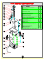
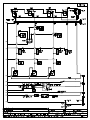
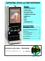
1. SCREW, S.S., 1/4 - 20 x 5/8
2. SHIM ASSEMBLY, HEAT SINK W/HI-LIMIT BRACKET
3. HEATER, 120V 1700W
HEATER, 240 V, 3000W
4. O-RING, HEATER GASKET
5. HI-LIMIT, #500, 200°F CUTOUT
6. HEATSINK, 1/8" ALU. F/ HI-LIMIT
7. TUBE (K530A optional)
8. LEVEL CONTROL SENSOR [K402A & P410A]
9. RUBBER GASKET, FOR SCREW (ITEM 1 P446A)
10. RUBBER GASKET, FOR FLOAT SWITCH
11. FLOAT SWITCH 70.V.A [WAS L380A]
12. SILICONE BUTT SPLICED GASKET (GB 2M/2MD/ 1&2V/ 1&2V-CC)
SILICONE BUTT SPLICED GASKET (GB 3M/3MD/3V/3V-CC/2D)
SILICONE BUTT SPLICED GASKET (GB 4M/4MD/3D)
SILICONE BUTT SPLICED GASKET (GB4D)
13. DISPENSE VALVE (DUMP)
14. DIRECT MOUNTING SEAL (.466 ID)
15. DRAIN PLUG
16. DRAIN HOSE, SILICONE
17. TANK INSULATION MATERIAL
18. TANK WELDMENT ASS'Y (SEE METAL PARTS IDENT. LIST)
19. THERMOSTAT KNOB
20. THERMOSTAT (120V ONLY) [WAS L266A]
THERMOSTAT (120/240V ONLY)
21. TANK TOP (SEE METAL PARTS IDENT. LIST)
22. BREATHER HOSE [not shown]
* QUANTITY SHOWN IS FOR GB3, QUANTITY VARIES FOR EACH UNIT.
P465A
3
K667Q
1
G267A
1
G266A
1
M773A 1
L656A
1
K661A
1
K525A 2
K355Q 1
M533A 2
M532A 1
L499A 1
M498A 1
M499A 1
M500A 1
M473A 1
L467A 3*
M461A 6*
M391A 1
M483A 1
M183A
-------M008A 1
L532A
1
L029A
-------M626A 1
53*
52
51
50
49
1
48
47
46
45*
2
44
43
3
42
4*
41
40
39
38
37
5
6
36
Z:\DRAWINGS\NA000\NA33A-C-GB-MAN.dwg, 03/20/2002 03:53:32 PM, 1:1
7
35
8
9
10
34
CCW
11
33
CCW
12
CCW
32
13
31
14
15
16
17
18 19
20
ILL. J
21
22
23* 24* 25
26
27
28
29
30
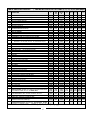
PARTS IDENTIFICATION LIST
ITEM
1
2
3
5
6
7
8
9
10
11
12
13
14
15
16
17
18
19
20
21
22
25
26
27
28
29
30
31
32
33
34
35
36
37
38
39
40
41
42
43
44
46
47
48
49
50
51
52
(* See METAL PARTS LIST for ITEMS 4, 23, 24, 45, 53 [next page])
DESCRIPTION
SILICONE HOSE [WATER INLET VALVE-—TANK] [ .375 I.D. x 13” ] M484A
SILICONE HOSE [BREATHER FITTING/TANK—DRAIN] [ .375 I.D x 32”.] M485A
SILICONE HOSE [DISPENSE VALVE - DISPENSE GROMMET] [ .313 I.D x 14.5”.] M619A
CHECK VALVE [PREVENTS BACKFLOW]
HOSE NUT ASS’Y
WATER INLET VALVE 120 [120/240 ] [was L462A]
FUSE HOLDER (120/240V only)
BUSSMAN SC15 FUSE (120/240V only) or
STEPDOWN TRANSFORMER (240/120V only)
POWER CORD
CONTACTOR GB5M ONLY
WATER LEVEL CONTROL BOARD (CCA)
TERMINAL BLOCK FOR 120V [WAS B117A]
[FOR 240V USE B116A]
TRANSFORMER [use w/DC motor & Speed Control CCA] - OPTIONAL
SPEED CONTROL BOARD [Controls Auger Speed GRAM THROW] - OPTIONAL
FAN [GB1,2,3 CD56A]
[GB4,5 CD224 110-115V, 60HZ, 110cu.m./hr., AC] w/ RW31Q Fan Housing Ass’y
ELBOW INSERT [USE W/ FAN CD56A ONLY]
DUCT HOSE [FAN EXAUST] (16” X 1” ø)
[WAS CD107]
1” FEET OR 4” LEGS M172A (SET OF 4)
RINSE SWITCH [ GB1 & GB5 - L069A; GB2 - L299A; GB3 - L446A; GB4 - L470A ]
POWER SWITCH (120 V)
OR [FOR 120/240 V USE L299A]
HEATER INDICATOR LIGHT (amber)
WHIPPER MOTOR short shaft OR CHAMBER MOUNT SUPPORT BAR [for Coffee]
SLINGER DISC
GROMMET CHAMBER MOUNTING
CHAMBER MOUNT [USE BAR FOR COFFEE]
“O” RING # 125 (used w/ grommet CD66A)
WHIP BLADE - WITH STRAIGHT PROPELLERS OR [CD143 W/ BEV. PROP. FOR SOUP]
EXTENSION TUBE PLASTIC (was H265A & H409A)
OR S.S. FOR SOUP & COFFEE
WHIP CHAMBER
MIXING CHAMBER [ALTERNATE CD62A W/ RECTANGULAR WING]
DISPENSE CAP OR SPLASH GUARD
“O” RING (#110) (used w/socket CD67A)
MIXING BOWL SOCKET (was CD100 W/O RING M480)
DISPENSE BUTTON / SWITCH
STOP BUTTON/SWITCH [USED WITH TEACH ME TIMERS]
BALLAST [MOUNTED INSIDE DOORS FOR ALL GB4/5]
LAMP HOLDER
STARTER BASE (for lamp inside door)
STARTER, TYPE FS - 5, 5-6-8 WATT
DOOR LATCH
BULB, TYPE F8T5/CW
CLEANING INSTRUCTIONS
TIMER “TEACH ME” [PROGRAM. DISPENSE TIME/CUP SIZE]-SINGLE [TRIPLE L582A] OR
TIMER [NOT PROGRAM.] [USE W/POT. L577A & DIAL/CUP SIZE LABELS: NF32A/33A/34A
RELAY, OMRON (Essex B049A older units) FOR MANUAL UNITS
POTENTIOMETER - USED W/SPEED CONTROL BD [GRAM THROW DIAL]
USE W/ GRAM THROW DIAL- LABEL- GB2 NF30A; GB3 ND81A; GB4 NF31A
HEATER SWITCH, 30A SPST [120V] [FOR120/240V USE L299A]
PRODUCT GUIDE [GB2M-C USE AS ALTERNATIVE CD90A]
CANISTER ASS’Y WITH COVER [w/NYLON auger] OR
CANISTER ASS’Y WITH COVER [w/WIRE auger]
AC AUGER MOTOR (90 RPM CD73A, (44 RPM CD87A) [CD175 SAME AS CD150]
DC AUGER MOTOR 90 RPM CD151 [W/SCREW P443A] PORTION CONTROL - OPTIONAL
GB
GBM
GBM
S/S
GBM 5.5
GBM 5.5
S/S
M484A
M485A
M619A
L463A
K178A
CD257
C396A
CE181
CE187
C032A
M484A
M485A
M619A
L463A
K178A
CD257
C396A
CE181
CE187
C032A
M484A
M485A
M619A
L463A
K178A
CD257
C396A
CE181
CE187
C032A
M484A
M485A
M619A
L463A
K178A
CD257
C396A
CE181
CE187
C032A
M484A
M485A
M619A
L463A
K178A
CD257
C396A
CE181
CE187
C032A
M484A
M485A
M619A
L463A
K178A
CD257
C396A
CE181
CE187
C032A
M484A
M485A
M619A
L463A
K178A
CD257
C396A
CE181
CE187
C032A
L398A
60105
CF29A
L556A
CD56A
CD224
CD108
CD214
M042A
Å
L069A
C002A
CD75A
CD124
CD66A
CD65A
M379A
CD64A
M467A
CD63A
CD137
CD61A
M378A
CD67A
L455A
L584A
CE221
CE220
B128A
L396A
M367A
CE76A
N978A
L576A
L493A
B129A
L398A
60105
CF29A
L556A
CD56A
CD224
CD108
CD214
M042A
Å
L069A
C002A
CD75A
CD124
CD66A
CD65A
M379A
CD64A
M467A
CD63A
CD137
CD61A
M378A
CD67A
L455A
L584A
CE221
CE220
B128A
L396A
M367A
CE76A
N978A
L576A
L493A
B129A
M484A
M485A
M619A
L463A
K178A
CD257
C396A
CE181
CE187
C032A
L533A
L398A
60105
CF29A
L556A
CD56A
CD224
CD108
CD214
M042A
Å
L069A
C002A
CD75A
CD124
CD66A
CD65A
M379A
CD64A
M467A
CD63A
CD137
CD61A
M378A
CD67A
L455A
L584A
CE221
CE220
B128A
L396A
M367A
CE76A
N978A
L576A
L493A
B129A
L398A
60105
CF29A
L556A
CD56A
CD224
CD108
CD214
M172A
Å
L069A
C002A
CD75A
CD124
CD66A
CD65A
M379A
CD64A
M467A
CD63A
CD137
CD61A
M378A
CD67A
L455A
L584A
CE221
CE220
B128A
L396A
M367A
CE76A
N978A
L576A
L493A
B129A
L398A
60105
CF29A
L556A
CD56A
CD224
CD108
CD214
M042A
Å
L069A
C002A
CD75A
CD124
CD66A
CD65A
M379A
CD64A
M467A
CD63A
CD137
CD61A
M378A
CD67A
L455A
L584A
CE221
CE220
B128A
L396A
M367A
CE76A
N978A
L576A
L493A
B129A
L398A
60105
CF29A
L556A
CD56A
CD224
CD108
CD214
M042A
Å
L069A
C002A
CD75A
CD124
CD66A
CD65A
M379A
CD64A
M467A
CD63A
CD137
CD61A
M378A
CD67A
L455A
L584A
CE221
CE220
B128A
L396A
M367A
CE76A
N978A
L576A
L493A
B129A
L398A
60105
CF29A
L556A
CD56A
CD224
CD108
CD214
M042A
Å
L069A
C002A
CD75A
CD124
CD66A
CD65A
M379A
CD64A
M467A
CD63A
CD137
CD61A
M378A
CD67A
L455A
L584A
CE221
CE220
B128A
L396A
M367A
CE76A
N978A
L576A
L493A
B129A
L398A
60105
CF29A
L556A
CD56A
CD224
CD108
CD214
M042A
Å
L069A
C002A
CD75A
CD124
CD66A
CD65A
M379A
CD64A
M467A
CD63A
CD137
CD61A
M378A
CD67A
L455A
L584A
CE221
CE220
B128A
L396A
M367A
CE76A
N978A
L576A
L493A
B129A
L557A
L557A
L557A
L557A
L557A
L557A
L557A
L557A
L069A
CD70A
CD120
CD152
CD175
L069A
CD70A
CD68A
CD98A
CD175
L069A
CD70A
CD120
CD152
CD175
L069A
CD70A
L069A
CD70A
CD120
CD152
CD175
L069A
CD70A
L069A
CD70A
CD68A
CD98A
CD175
L069A
CD70A
CD68A
CD98A
CD175
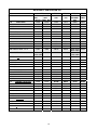
* See METAL PARTS LIST for ITEMS 4, 23, 24, 45, 53 [next page]
17
GBK
CD155
CD175
GBK 5.5 GB SKI
CD105
CD175
GB-LP
OCS
9/25/01
METAL PARTS IDENTIFICATION LIST
MODEL
GB1M
SPACE SAVER
GB2M
GB2M-5.5
GB3M-5.5
GB3M -10 LEFT
[ 11.5”W ]
GB3M -10 RIGHT [ 11.5”W]
GB4M-5.5
GB4
[17” W]
GB4M-11
[17” W]
GB5M-5.5
[17” W]
GB5M-10
[18” W]
GB6M-10 W/STEEL DOOR
[21.5” W]
GB8M-10 W/STEEL DOOR
[27” W]
GB1M-S/S
S/S
GB2M-5.5-S/S
GB3M-5.5-S/S
GB2M-W [w/hot water]
GB3M-W [w/hot water]
GB4M-W [w/hot water]
GB2M-8
FEATURE FLAVOR
GB2M-8W [w/hot water]
GB3M-8
WAS GB4M-8
GB3M-8W [w/hot water] WAS GB4M-8W
GB1K
GB2K
GB3K
GB4K
GB5K
ECONOMY W/ MOLDED DOOR
[32” H]
[32” H]
[32” H]
[32” H]
GB2K-5.5 SPACE SAVER W/ MOLDED DOOR
GB3K-5.5
[34” H]
ITEM 4
TANK
| TANK TOP
ASS’Y
| ASS’Y
[1 HEATER 1.8KW or 3KW]
SC35C
SC32C
SC35C
SC32C
SC35C
SC32C
SC36C
RI39C
SC36C
RI39C
SC36C
RI39C
RL72C
RL69C
SJ61C
SJ60C
SJ61C
SJ60C
SJ61C
SJ60C
SJ61C
SJ60C
ITEM 23
DRIP TRAY
GRILL
ITEM 24
DRIP TRAY
PAN
RI23A
RI18A
RI18A
RI19A
RO07A
RO07A
RI20A
SD76A
SD76A
SD76A
RR34A
RI11A
RI11A
RI11A
RI12A
RO04A
RO04A
RH05A
RT66A
RT66A
RT66A
RR33A
ITEM 45
DOOR
WELDMENT
ASSY
RD03Q
RD03Q
RH47Q
RH48Q
RN98Q
RN93Q
RH49Q
SE45Q
RZ90Q
RM02Q
SD82Q
ITEM 53
SIDE
PANELS
SL76A
RK14A
RK14A
RK14A
RH91A
RH91A
RH91A
RH91A
RH91A
RG48A
RG48A
RN90A
RN90A
RG48A
RG48A
RG48A
RG48A
RG48A
SJ61C
SJ60C
SM14A
SM13A
SM90Q - LEFT
RL72Q -RIGHT
SC35C
SC35C
SC36C
SC35C
SC36C
RL72C
SL69C
SM97A
SL84A (2)
SC32C
SC32C
RI39C
SC32C
RI39C
RL69C
RI23A
RI18A
RI19A
RI18A
RI19A
RI20A
RI11A
RI11A
RI12A
RI11A
RI12A
RH05A
SM40Q -UPPER
SM12Q -LOWER
SL72Q -UPPER
SL74Q -LOWER
RK18Q
RM51Q
RM52Q
RD03Q
RD02Q
RD76Q
SC36C
SC36C
RL72C
RL72C
RI39C
RI39C
RL69C
RL69C
RM86A
RI19A
RI53A
RI20A
RI12A
RI12A
RH05A
RH05A
RD02Q
RD02Q
RD76Q
RD76Q
RH91A
RH91A
RH91A
RH91A
SC35C
SC35C
SC35C
RL72C
RL72C
SC32C
SC32C
SC32C
RL69C
RL69C
RLO78A
RK44A
RK47A
RZ79A
RZ79A
RM21A
RM21A
RM23A
RZ80A
RZ80A
RF73Q
RF73Q
RF79Q
RZ07Q
RZ07Q
RD46A
RD46A
RD46A
RD46A
RD46A
SC35C
SC36C
SC32C
RI39C
RI18A
RI19A
RI11A
RI12A
RH47Q
RH48Q
RG48A
RG48A
SL76A
GB2 – LP
GB3 - LP
GB4 - LP
LOW PROFILE
SC35C
SC36C
SC36C
SC32C
RI39C
RI39C
SC25A
SC30A
SC57A
SC26A
SC31A
SC58A
SC01Q
SB30Q
SC62Q
SC33A
SC33A
SC33A
GB1SKI
GB2SKI
SKI
RL54C
RN21C
RL52C
RN16C
RI23A
RL61A
RI11A
RH05A
RF37Q
RF23Q
RL51A
RL51A
18
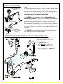
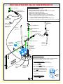
HOT/COLD WATER VALVE CONVERSION KIT
INSTALLATION INSTRUCTIONS:
1. REMOVE EXISTING BOTTOM BACK PANEL.
2. INSTALL KIT/PANEL WITH THE 4 SCREWS SUPPLIED.
3. CONNECT HOSE (FROM TANK) WATER INLET, TO DUAL VALVE AS SHOWN.
4. CONNECT HOSE TO RIGHT DISPENSE VALVE.
5. CONNECT HOSE TO RIGHT MIXING CHAMBER SOCKET.
6. CONNECT TOGGLE SWITCH WIRES AS FOLLOWS: (see Wiring Diagram)
a. Disconnect Yellow wire from RIGHT Dispense Valve (coming from motors)
& Connect to CENTER Terminal of HOT/COLD Switch.
b. Connect Flag Terminal from HOT/COLD Switch to RIGHT Dispense Valve.
c. Check HOT & COLD operation to make sure that the HOT/COLD leads are not reversed.
SWITCH LABEL NB10A
HOT/COLD SWITCH
BEHIND HOPPER L497A
yel
Connect To RIGHT
DISPENSE VALVE
yel
Connect To
RIGHT Dispense
Valve
yel
Disconnect Existing
wire From RIGHT
DISPENSE VALVE &
Connect Here
FLOW ADJUSTMENT KEY
From Tank
ADJUSTER (HEX HEAD PLUG)
(Incoming Water
Line)
WASHER
FLOW CONTROL k415C
HOSE BARB FITTING M576A
M564A
ELBOW
K555A
WATER INLET
CONNECTOR
W/ 1/4 FLARE
FITTING
FLOW CONTROL ASS'Y
Connect To
Water Inlet
DUAL VALVE .75
gpm W/FLOW
WASHER TO
REGULATE BOTH
SIDES
Connect To
RIGHT MIX.
CHAM. SOCKET
yel
wht
OPERATION INSTRUCTIONS :
BOTH HOT AND COLD WATER FLOW RATE IS FACTORY ADJUSTED, THE WATER
FLOW RATE MAY BE CHANGED IF THE USER DESIRES AS FOLLOWS:
A. SET HOT/COLD SWITCH TO COLD (bypass tank ass'y):
TO ADJUST THE COLD WATER FLOW USE THE FLOW ADJ. KEY.
CONNECT TO
LEVEL CONTROL
BOARD
CONNECT TO
TERMINAL BLOCK
NEUTRAL
1. CLOSE ADJUSTER WITH KEY.
2. OPEN ADJUSTER SLOWLY WITH KEY.
NOTE: WATER WILL SHOOT OUT OF VENT TUBE OF DISPENSE VALVE,
IF ADJUSTER IS NOT ADJUSTED AS DIRECTED.
3. ADJUST COLD WATER LEVEL IN THE
THE MIX. CHAMBER TO LEVEL SPECIFIED HERE,
WHICH WILL YIELD 33 gr/8 oz. OF CAPPUCCINO.
IF WATER LEVEL IS ABOVE THE MAX POINT,
IT WILL LEAK OUT.
B. SET HOT/COLD SWITCH TO HOT :
TO ADJUST THE HOT WATER FLOW
USE DISPENSE VALVE. SEE ILL. C.
19
CCW
MAX
PROPER
WATER
LEVEL
+
+
CECILWARE CORPORATION
+
CECILWARE CORPORATION
CECILWARE CORPORATION
CECILWARE CORPORATION