1
Colour TV
Service Manual
2
Model Group: CT-14GT9
CHASSIS: CN-ER
MODEL:
CT-14GT9A
CT-14GT9CP
CT-14GT9N
CT-14GT9R
Model No: CT-14GT9A_14GT9CP_14GT9N_14GT9R
Version 1.0
3
CONTENTS
Specifications ..........................................……………………………... 04-04
X-Ray Radiation Precaution …......………………….…………………. 05-05
Safety Precaution .............................................................................. 05-05
Product Safety Notice ……………………………………....……………05-05
Alignment and Test Instructions ........................................................ 06-14
Electrical Parameters of Main IC and Components ........................…15-19
Troubleshoot Flowchart .................................................................... 20-24
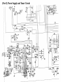
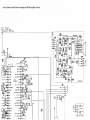
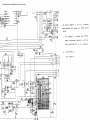
Schematic Diagram …………......………………………………………. 25-28
Model No: CT-14GT9A_14GT9CP_14GT9N_14GT9R
Version 1.0
4
SPECIFICATIONS
RECEIVING SYSTEM
Sound System
: A = BG/DK/I/M, R, N = BG/DK/I, CP = BG
Colour System
: A = PAL/SECAM/NTSC/NTSC P/B
R, N = PAL/SECAM/NTSC P/B
CP = PAL/NTSC P/B
Picture Tube
Ext. Antenna
Ext. In/Out
Audio Output
Volts
Power Consumption
Dimension
Net Weight
: 14” = 37cm diagonal
: 75 Ohm Coaxial Cable
: Audio/Video-in/out
: 2W + 2W (THD ≤ 7%)
: A = AC100 ~ 260V 50/60Hz
R, N, CP = AC150 ~260V 50/60Hz
: 14” = 60W
: 14” = 450(W) x 410(D) x 378(H) mm
: 14” (10 kg)
REMOTE CONTROL
Transmitting System
Power Supply
: Infra-red
: DC 3V (1.5Vx2)
Design and specifications are subject to change without prior notice
Model No: CT-14GT9A_14GT9CP_14GT9N_14GT9R
Version 1.0
5
CAUTION
Before serving the chassis, read the “X-Ray Radiation Precaution”, “Safety Precaution” and
“Product Safety Notice” on this page.
X-RAY RADIATION PRECAUTION
1. Excessive high voltage can produce potentially hazardous X-Ray Radiation. To avoid such hazards,
the high voltage must not be above the specified limit. The normal value of the high voltage of this
receiver is 24KV at zero beam current (minimum brightness) under 220V AC power source. The
high voltage must not, under any circumstances, exceed 30KV.
2. Each time a receiver requires servicing, the high voltage should be checked following the High
Voltage Check procedure in this manual. It is recommended the reading of the high voltage should
be recorded as a part of the service record. It is important to use an accurate and reliable high
voltage meter.
3. The primary source of X-Ray Radiation in this TV receiver is the picture tube. For continued XRay Radiation protection, the replacement tube must be exactly the same type tube as specified in
the part list.
4. Some parts in this receiver have special safety – related characteristics for X-Ray Radiation
protection. For continued safety, parts replacement should be undertaken only after referring to the
Product Safety Notice.
SAFETY PRECAUTION
Warning: Service should not be attempted by anyone unfamiliar with necessary precaution on this
receiver. The following are the necessary precautions observed before servicing this chassis.
1. Since the power supply circuit of this receiver is directly connected to the AC power line, an
isolation transformer should be used during any dynamic service to avoid possible shock hazard.
2. Always discharge the picture tube anode to the CRT conductive coating before handling the picture
tube. The picture tube is highly evacuated and if broken, glass fragment will be violently expelled.
Use shatter proof goggles and keep picture tube away from the unprotected body while handling.
3. When replacing a chassis in the cabinet, always be certain that all the protective devices are put
back in place, such as: non-metallic control knobs, insulating covers, shields, isolation resistorcapacitor network etc.
4. When replacing parts or circuit boards, disconnect the power cord.
5. When replacing a high voltage resistor (Metal oxide film resistor) on circuit board, keep the resistor
10mm (1/2in.)away from circuit board.
6. Connection wires must be kept away from components with high voltage or high temperature.
7. If any fuse in this TV receiver is blow, replace it with the FUSE specified in the chassis part list.
8. The receiver is designed to operate with 220V(50/60Hz) AC mains.
PRODUCT SAFETY NOTICE
Many electrical and mechanical parts in this chassis have special safety –related characteristics. These
characteristics are often passed unnoticed by a visual inspection and the X-Ray Radiation protection
afforded by them cannot necessarily be obtained by using replacement components rated for high
wattage, etc. Replaced parts which have these special safety characteristics are identified in this manual
and its supplements, electrical components having such features are shaded on the schematic diagram and
the part list.
Before replacing any of these components, read the part list in this manual carefully. The use of substitute
replacement parts, which do not have the same safety characteristics, as specified in the part list may
create shock, fire, and X-Ray Radiation or other hazards.
Model No: CT-14GT9A_14GT9CP_14GT9N_14GT9R
Version 1.0
6
ALIGNMENT AND TEST INSTRUCTION
MAIN CHASSIS ALIGNMENT INSTRUCTION
Equipment requirement:• Colour Television signal generator or Central TV signal generator
• IF alignment – Philips Gen. 5418 or 5518
• Scope 20 MHz – 2 channels types
• Digital multi-meter with LED display 4 digits
• Factory remote transmitting jig / Factory mode remote control unit
AV Input/Output Inspection
• Inspection Equipment
a. Standard video signal source (PAL)
b. Standard video signal source
c. (NTSC) S- VIDEO signal source
d. Audio signal source
e. Remote controller
f. Jig
g. Oscilloscope (Dual channel)
•
AV Input Inspection
a. Set the TV to the AV mode. Send 1 Vpp (Loading: 75 ohm) PAL, NTSC and
SECAM AV signals into the AV IN terminals on the TV respectively. Check
and make sure that the picture, sound and color in every system are normal.
b. If the TV has front-set or side-set AV IN terminals, check the AV IN terminals
for normality.
c. If the TV has several sets of AV IN terminals, check every AV IN channel.
d. If the TV has S-VIDEO IN terminals, check the S-VIDEO IN channel.
e. If the TV can output AV stereo, inspect the AUDIO IN L/R channels
respectively.
Note: It's not necessary to check SECAM signal input if the TV can't receive SECAM signals.
•
AV Output Inspection
a. Power on the TV to receive Z16 white full-field signal in the TV mode.
b. Check audio output with the oscilloscope and make sure that 1KHZ (1±0.2Vpp)
sine wave is available.
c. Check video output with the oscilloscope and ensure that l±0.2Vpp (Loading: 75
ohm) is available.
d. Send AV signals into the TV's AV IN terminals following the instructions stated
in 1.2 The TV should output different A V signals respectively.
Note: With S-VIDEO signal input, it's not necessary to check A V output.
Degaussing Coil inspection
• Inspection Requirement
a. Degaussing coil inspector
• Inspection Method
a. Dismount the automatic degaussing coil plug from the socket. After it cools,
remount the coil plug into the socket. Check internal degaussing effect and
ensure proper function. You may also use a magnetic sensor specially for
degaussing inspection
Model No: CT-14GT9A_14GT9CP_14GT9N_14GT9R
Version 1.0
7
To Inspect Functions of Buttons and Remote Controller
• Inspection Equipment
a. Remote controller
b. Inspected Buttons on the TV
c. TV/A V
d. POSITION UP/DOWN
e. VOLUME UP/DOWN
f. MENU
• Inspected Buttons on the remote Controller
a. POWER ON/STANDBY
b. POSITION UP/DOWN
c. TV/A V
d. VOLUME UP/DOWN
e. OSD
f. MENU
g. MENU SELECT( ↑ / ↓ )
h. MENU ADJUSTMENT ( → / ← )
i. PICTURE MODE SELECT
j. PRESET
k. DIRECT SELECT ( 0 ∼ 9 and − / − −)
l. MUTE
m. OFF TIMER
n. GAME
o. BROWSE
p. OK
• To Inspect Functions of Buttons and Remote Controller
a. Power on the TV so that normal operation begin.
b. Check every button on the TV in turn and ensure that all buttons work normally
and feel smooth.
c. Check every button on the remote controller in turn and ensure that all buttons
work normally.
Inspection for Automatic Gain Control (AGC)
• Inspection Equipment
a. Remote transmitting jig
• Inspection Method
a. Check and make sure that both picture and sound are normal when the TV
receives 90dB signal, and signal to-noise ratio is O.K. with 90dB signal
reception. If not, press the AGC button to adjust AGC data until the above
requirements are fulfilled.
b. Check signals from other channels and ensure that the picture and sound are
normal.
Inspection for Sound Intermediate-frequency (SIF)
• Inspection Equipment and Signals
a. 70db standard multi-sound-system color TV signals
b. Remote transmitting jig
c. Audio voltmeter
d. Oscilloscope
• Inspection Method
a. Receive standard color TV signals in different sound systems (M, B/G, I, D/K)
respectively. Signal source is set to be modulation signal of 50KHz ±1KHz.
b. Press the SOUND SYS button on the remote transmitting jig to select proper
sound system respectively. Check AUDIO OUT terminals with the oscilloscope
and make sure that 1KHZ (1±0.2Vpp) sine wave is available and no noise and
buzz are generated from the speakers.
c. Measure the distortion-free voltage of the speakers to be no less than 4Vrms with
the audio voltmeter.
Model No: CT-14GT9A_14GT9CP_14GT9N_14GT9R
Version 1.0
8
Aging
•
•
•
•
•
•
•
•
•
Aging Setting
Equipment to Be Required
Remote controller
Setting Method
Set the volume to 0, and brightness, contrast and chroma to maximum.
Set the TV in the M mode.
Aging Voltage and Aging Time
Increase the rated operating voltage by 10%, to 242V
Aging time is not less than 2 hours.
Fine Tuning and Inspection After Aging
• Equipment and Signal to Be Required
• Voltmeter
• High-frequency effective voltmeter
• Anode high-voltage tester
• Adjustment and Confirmation of +B Voltage, Heater Voltage and Anode Voltage
• Power on the TV to receive grille pattern signal.
• Check the resistor and coil for being burned. (If the fuse is burned-out, do not power on the
TV again until the cause is found out.)
• Measure voltage of TP-I30 with the digital voltmeter and set voltage of the potentiometer
RP551 to 130 ± 1V
• Measure the heater voltage with the high-frequency effective voltmeter and anode voltage
with the anode high-voltage tester. The readings are shown as below.
Table
Test Point
Heater pin of socket
CRT anode (Small neck)
CRT anode (Large neck)
CRT anode (True flat)
CRT anode (14”)
Type of voltage
Heater voltage
High voltage
High voltage
High voltage
High voltage
Voltage Value ( V )
6.3 ± 0.3V
25 ± 1.5kV
26 ± 1.5kV
26.5 ± 1.5kV
21.5 ± 1.5kV
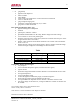
Inspection for Purity and Convergence
• Purity Inspection
• Receive white full-field pattern signal (or red full-field video signal).
• Degauss the CRT.
• Check purity with monochromatic signals in magnetic-free equipment and ensure to come
up to the following standard.
• Convergence Inspection
• Receive grille pattern signal.
• Decrease the brightness and contrast properly to check convergence.
• Check if the convergence meets the following specifications.
• Convergence difference dependent on time in Section A should be less than O.5mm
• With supply voltage of 160~260V AC, convergence difference in Section A should be less
than 0.5mm
If not, readjust it again. Observe with a magnifying glass.
Section A: Purity offset is not allowed.
Note: Section A is a circle with effective screen height as its diameter.
Section B: 1/4 purity offset is allowed.
Model No: CT-14GT9A_14GT9CP_14GT9N_14GT9R
Version 1.0
9
Rough Adjustment of White Balance (Dark Balance Adjustment) and Focus Adjustment
Adjustment Equipment
a. Remote transmitting jig
b. Adjustment Method
c. In the TV mode, set the brightness to 32 and contrast, chroma, sub brightness
and sub contrast to 0. Set BLUE BACK off. Disconnect the signal cable.
d. Press the V KILL button on the remote transmitting jig so that the screen is
displayed as a horizontal bright line.
e. Adjust the screen potentiometer so that only a horizontal line appears on the
screen. Take the primary color accounting for a large proportion of the three
primary colors RGB as reference (for example, if the bright line is more green,
take G gun as reference.) Adjust dark balance of the other two primary colors
with the remote transmitting jig, but not adjust the reference gun. Roughly set
the bright line to white.
f. The horizontal line should not be too bright or too dark. If the line is too bright
or too dark, repeat step c. Then FIX the screen potentiometer.
g. Press the V KILL button on the remote transmitting jig so that raster appears on
the whole screen. Set the sub brightness and sub contrast to 63, and picture mode
to STANDARD.
h. Receive CH-5 circle pattern signals. Adjust FCB on the FBT until good raster
focus and high-definition picture are obtained.
Model No: CT-14GT9A_14GT9CP_14GT9N_14GT9R
Version 1.0
10
Adjustment for Automatic White Balance
a. Adjustment Equipment
b. White balance adjuster
c. PC
d. Adjustment Method
e. Insert the cord plug connected with the PC into the socket XS701 on the main
chassis board.
f. Control the PC to give an instruction to set the TV in the white balance
adjustment mode.
g. The PC automatically adjusts white balance. After completion, the PC gives an
instruction to end the adjustment and reminds you of completion of adjustment
on the screen. At this time, pull off the cord plug XS701.
Inspection and Adjustment of Sub Brightness and Contrast
h. Adjustment Equipment
i. Remote transmitting jig
j. Oscilloscope
Methods of Inspection and Adjustment
k. Power on the TV to receive CH-21 pattern signal.
l. The inspection and adjustment should be done after completion of adjustments
of white balance and focus.
m. Set the picture mode to VIVID.
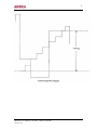
n. Press the SUB BRI button on the remote transmitting jig to adjust sub brightness
data until 4th, 5th monochrome staircase on the center of CH-21 can be just
seen.
o. Receive CH-3 pattern signal.
p. Set the brightness, contrast and chroma to 32, 63 and 0 respectively.
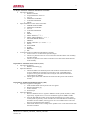
q. Check G gun with the oscilloscope and ensure that the contrast is not less than
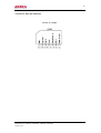
70Vp-p as shown below.
Model No: CT-14GT9A_14GT9CP_14GT9N_14GT9R
Version 1.0
11
Model No: CT-14GT9A_14GT9CP_14GT9N_14GT9R
Version 1.0
12
Video Geometry Adjustment
• Adjustment Equipment
a. Remote transmitting jig
•
PAL Video Geometry Adjustment
a. Switch on the TV to receive CH-5 PAL circle pattern signal.
b. Press the H CEN button on the remote transmitting jig to adjust H CEN data so
that horizontal center of the picture coincides with horizontal center of the CRT.
c. Press the V SIZE button on the remote transmitting jig to adjust V SIZE data so
that the video vertical amplitude is within the range of 2mm from .lower or
upper chessboard disappearing dots.(over 2mm is allowed if vertical
reappearance ratio is ensured to be not less than 90% and regular circle can be
available.)
d. Press the V LIN button on the remote transmitting jig to adjust V LIN data so
that circle pattern is good in vertical linear.
e. Press the V POS button on the remote transmitting jig to adjust V POS data so
that vertical center of the picture coincides with vertical center of the CRT and
center of the picture is within the range of 2mm from vertical center of the CRT.
f. Press the V SC button on the remote transmitting jig to adjust VSC data so that S
curve distortion doesn't exit on vertical of the circle pattern.
g. Check and make sure vertical linear ofCH-5 circle pattern signal is good. If not,
repeat above steps c ∼ f .
•
NTSC Video Geometry Adjustment
a. Switch on the TV to receive CH-I0 NTSC circle pattern signal.
b. Press the H CEN button on the remote transmitting jig to adjust H CEN data so
that horizontal center of the picture coincides with horizontal center of the CRT.
c. Press the V SIZE button on the remote transmitting jig to adjust V SIZE data so
that the video vertical amplitude is within the range of 2mm from lower or upper
chessboard disappearing dots (over 2mm is allowed if vertical reappearance ratio
is ensured to be not less than 90% and regular circle can be available).
d. Press the V POS button on the remote transmitting jig to adjust V POS data so
that vertical center of the picture coincides with vertical center of the CRT and
center o{ the picture is within the range of 2mm from vertical center of the CRT.
e. Check and make sure vertical linear of CH-5 circle pattern signal is good. If not,
repeat above steps c ∼ d.
12. Adjustment and Inspection of Horizontal Amplitude
• Equipment to Be Required
a. Ceramic screwdriver
•
Horizontal Amplitude Adjustment
a. Switch on the TV to receive CH-5 circle pattern signal.
b. Adjust the horizontal amplitude inductor L442 so that the horizontal amplitude
ensures reappearance ratio to be 92%.
c. If not cut out C436. Then recheck the high voltage and heater.
13. Inspection of Picture and Color
• Signals to be required
a. PAL, D/K color test cards
b. NTSC, M color test cards
c. SECAM, BIG color bar signals
Model No: CT-14GT9A_14GT9CP_14GT9N_14GT9R
Version 1.0
13
•
Inspection Method
a. Receive PAL color test card signal. Check picture definition dependent on
definition of 3.8MHz in multi wave group.
b. Check reflection after observing black line with white background on top of the
circle and white line with black background on bottom of circle of the circle
pattern.
c. Check if the colors of the circle pattern arrange in the order of white, yellow,
dark green, green, purple, red, blue and black.
d. Check time delay difference between the brightness channel and chroma
depending on distinctness of the vertical boundary of yellow/red step signals on
bottom of the circle pattern or stagger boundary.
e. Check if phase and PAL delay are normal after inspecting color signals near
circle pattern signal circle. If reference sub carrier phase of the sync demodulator
in the TV is correct and delay demodulation and PAL switch are normal, color of
the vertical bar on the left/right of circle close to the frame should not appear
distinct, based on which checking amplitude proportion of primary color signal
sent to the CRT’s three cathodes for normality. If error occurs in the delay
demodulator and direct signal, line crawl exists on the parts mentioned-above. If
phase error occurs, line crawl exists on the second left vertical line and second
right vertical line of the circle pattern. It's normal that top and bottom of the
second left vertical line turn dark green and red respectively; top and bottom of
the second right vertical line turn yellow and blue respectively; tops and bottoms
of the third left vertical line and third right vertical line turn blue and yellow
respectively.
f. Receive SECAM color bar signal. Check if the color bars arrange in the order of
white, yellow, dark green, green, purple, red, blue and black and color is normal.
(For the TVs with SECAM signals reception)
g. Receive NTSC/M color card signals. Check and make sure that color bar display
is normal basically. Chroma changes accordingly as adjusting chroma. Color bar
sequence should be normal when chroma is set to optimum (visual estimation).
Audio Inspection (Only for the TV with the function of BBE)
• Inspection Equipment
a. Stereo audio source
b. Video signal source
• Inspection Method
a. Set the TV in the A V mode and send video and stereo audio signals into A V
terminals on the TV.
b. Press the BBE button on the remote controller to check BBE on/off. The audio
effect differs as BBE is turned on/off.
c. The audio effect differs accordingly as you adjust BBE treble and bass data with
BBE on
d. Call up the AUDIO menu by the remote controller. Check surround on/off. The
audio effect differs as surround is on/off.
e. The audio effect changes accordingly as you adjust the treble data in the AUDIO
menu.
f. The audio effect changes accordingly as you adjust the bass data in the AUDIO
menu.
g. The audio effect changes accordingly as you adjust the balance data in the
AUDIO menu.
15. Inspection for Mute under No Signal Condition and Blue Back On/Off
Pull off the ANTENNA IN cable and no sound should be heard from the speakers. Blue back should
appear or disappear when setting blue back on or off by the remote controller. Under no signal
condition, the TV will automatically shift to the STANDBY mode in 15 min.
Model No: CT-14GT9A_14GT9CP_14GT9N_14GT9R
Version 1.0
14
16. Safety Inspection
Test safety of all naked metal of the TV Supply high voltage of 3000V, 50Hz and current of 10mA to
the TV after ensuring that test rod contacts with tested point well. Test every point for 1 min. and
ensure no arcing and sparking.
17. Requirements for. Insulation Resistance
Measure resistance between naked metal of the TV and feed end of the power cord to be infinity with
DC-500 high resistance meter and insulation resistance between the naked metal and degaussing coil
over 20M ohm
18. Inspection for Weak Signals and Remote Functions
For the TVs through safety test, inspect open-circuited reception with signal strength of 40dB and
functions of the front-panel and remote controller.
19. To Increase / Decrease Voltage
The TV should work normally when the supply voltage ranges from 160V AC to 260V AC.
(Point the remote transmitting jig directly to the remote sensor. then press each button in turn. The TV
should operate accordingly.)
20. Inspection for Back Cover, Front Cover and Structure
• Check the front panel and screen for being clean and having scratches.
• Check every label for correctness.
• Check every button's position.
21. Ex-factory Setting
• Set the language for OSD to English.
• Set the picture mode to VIVID
Model No: CT-14GT9A_14GT9CP_14GT9N_14GT9R
Version 1.0
15
Electrical Parameters Of Main IC And Components
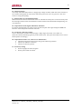
BIMOS IC Pins and Function
BIMOS IC LA76810
Model No: CT-14GT9A_14GT9CP_14GT9N_14GT9R
Version 1.0
16
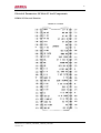
CPU IC Pins and Function
CPU IC CHT0400
Model No: CT-14GT9A_14GT9CP_14GT9N_14GT9R
Version 1.0
17
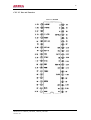
EEPROM IC Pins and Function
EEPROM ST24C04
Sound Amplifier IC Pins and Function
Sound Amplifier IC LA4225
Model No: CT-14GT9A_14GT9CP_14GT9N_14GT9R
Version 1.0
18
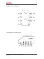
Vertical IC Pins and Function
Vertical IC LA7840
Model No: CT-14GT9A_14GT9CP_14GT9N_14GT9R
Version 1.0
19
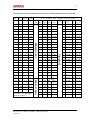
TRANSISTOR STATIC OPERATING POINT & IC’s OHMIC RESISTANCE TO GROUND
B
C
E
Base
Collector
Emitter
0.10
20
0.
V703
0.50
4.43
0.10
V183
0.02
0
0.10
3
1.75K
4
0.002K
3
7.30M
4
27.53K
V182
0.10
0.10
0.10
5
1.75K
6
1.76K
5
6.90M
6
6.91K
V804
0.09
0.10
0.10
7
1.70K
8
1.80K
7
0.002K
8
0.42K
V102
0.68
0
0.10
9
0
10
1.80K
9
7.50M
10
5.10K
V106
4.30
4.99
4.99
11
1.58K
12
1.52K
11
11.85K
12
11.0K
V553
6.87
35.90
6.30
13
1.64K
14
1.02K
13
5.22K
14
7.15K
V586
0.10
24.96
0.10
15
0
16
1.67K
15
7.25K
16
7.19K
V704
0.10
4.96
0.13
17
1.53K
18
1.75K
17
3.27K
18
0.36K
V141
0.10
0.64
0.61
19
1.72K
20
17.0K
19
5.67K
20
5.60K
V185
0.02
0
0.10
21
16.3K
22
4.95K
21
2.50K
22
7.30K
V181
0.10
0.10
0.10
23
1.56K
24
1.60K
23
2.20K
24
7.19K
V702
4.55
5.22
5.25
25
1.60K
26
1.65K
25
0.50K
26
8.93K
V803
0.10
2.80
1.60
27
1.69K
28
1.78K
27
1.40K
28
6.80K
V591
0.10
0.10
0.10
29
1.85K
30
1.78K
29
4.70K
30
7.20K
V101
1.33
7.07
0.58
31
1.00K
32
1.60K
31
0.548K
32
∝
V105
5.01
0.20
4.99
33
1.50K
34
1.60K
33
0.002K
34
7.20K
V107
5.01
0.10
4.99
35
1.83K
36
1.75K
35
7.038K
36
7.28K
V511
11.7
0.50
11.5
37
1.83K
38
1.75K
37
7.00K
38
7.30K
V512
0.50
0.50
0
39
1.75K
40
1.70K
39
7.04K
40
2.00K
V513
0.50
300
0
41
1.69K
42
1.73K
41
0.002K
42
7.50K
V431
0.20
17.0
0
1
0
43
0.429K
44
7.30K
V582
25.0
24.4
24.3
2
0.56K
V583
9.50
11.3
9.00
3
V702
4.50
5.10
5.20
V801
1.50
0
2.10
CPU CHTO400
N301 ( LAT840 )
Transistor Operating Point
during PAL Color Bar Signal
reception condition .
Type
No
IC OHMIC RESISTANCE TO GROUND
( Use R x 1K Range, With −VE Black Probe to Ground )
Pin Value Pin Value Type Pin Value Pin Value
No ( Ω ) No
No
No
No
(Ω)
(Ω)
(Ω)
1
1.75K 2
1.2K
1
6.80M
2
0.5K
N811
( LA4225 )
LA76810A
Item
No
V585
Value
(Ω)
1.62K
45
0.40K
46
0.72K
∝
Pin
No
1
47
7.31K
48
0.93K
4
1.67K
2
0
49
0.99K
50
7.32K
5
1.30K
3
0
51
7.24K
52
7.35K
6
1.50K
4
1.00K
53
7.27K
54
7.43K
7
1.45K
5
1.70K
Model No: CT-14GT9A_14GT9CP_14GT9N_14GT9R
Version 1.0
20
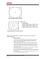
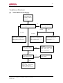
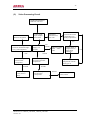
Troubleshoot Flowchart
(A)
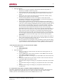
Switch Mode Power Supply
SWITCH MODE
POWER SUPPLY
FAULTY
0V
+130V Supply Line Abnormal
+300V Supply Normal. ?
Normal
0V
Too High
Too Low
Check for
Open-circuit Components
R556, VD561, V553,
VD515, V511, V512, R526
and etc
Check for
Open-circuit Components
R520 ∼ R524, V511, V512,
C515, C517 and etc
D701 pin31 voltage @
Low Voltage Level ?
Yes
Check for
Rectifier/Filter Circuit
V513 and associate
components.
Check for
Open-circuit Components
R520 ∼ R524, V511, V512,
C515, C517 and etc
No
D701 pin31 voltage @
High Voltage Level ?
No
Check for
Open-circuit Components
VD551, N505, V511,
V512, C515, C517, D510 .
Model No: CT-14GT9A_14GT9CP_14GT9N_14GT9R
Version 1.0
Yes
Check and replace
D701 if faulty
21
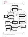
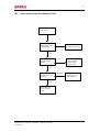
(B)
Micro-controller System Circuit
Remote Control System
Faulty
Check Keyboard Input
or Remote Control
Unit Input Command;
any respond ?
Keyboard input normal;
but no respond to remote
controller.
All no respond
Normal
Check IR
receiver
unit
HS0038
Remote Controller ;
normal ?
Abnormal
Respond to
commands
input but
during
search
tuning no
channel
locked on
Measure 0 ∼ 30V
tuning voltage; is it
normal ?
Normal
Abnormal
Normal
D701 Pin 14 AFC
voltage; is it normal ?
D701 pin 8 PWM output
signal waveform variation;
is it normal ?
Abnormal
Check charge
/discharge circuit
and channel ident
circuit.
Abnormal
Replace D701
Normal
Model No: CT-14GT9A_14GT9CP_14GT9N_14GT9R
Version 1.0
0V
Check X’tal Osc. Circuit
G701, C709, C710, D701
and Keyboard
Check and replace battery,
BM01, DM01, Vm01, and
key pad conductor
D701 band
selection voltage;
is it normal ?
Check D701 Pin 12, 17
voltage level; is it normal ?
Check V581, VD533,
C500, V702, D704,
C712 and replace if
found faulty
.components with the
Normal
Check V147, R141,
N141, R143, C141,
C744 and etc
0V
22
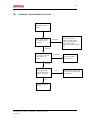
(C)
Video Processing Circuit
VIDEO PROCESSING
CIRCUIT FAULTY
Color Picture but
abnormal brightness
Video Signal
Input /Output
Waveform
Check N101 Pin 38,
39 associate circuit
components; any
faulty components?
Black and
White Picture,
No color
No
Under Service Align Mode
Check for horizontal bright
line @ VG2 alignment
O.K.
Check N181 pin 13
and associate
components
Normal
Check and replace
N101, D701 if
faulty.
Not
normal
Check +190V
supply; is it
normal?
No
VD555A, C908,
V901 ∼ V905,
CRT
Normal
Check N101 pin 46,
42, 40 and associate
components
Replace N101 or
readjust Service
Align Mode
parameters
Replace faulty
components with the
same type no
Normal
Check N101 pin 22
and associate
components
Model No: CT-14GT9A_14GT9CP_14GT9N_14GT9R
Version 1.0
Normal
Check D701 pin 37,
V801, V804
Yes
23
(D)
Inter-carrier Audio Processing Circuit
Color Picture Only
but No Sound
Reception of AV
Signal input; Any
sound output
Yes
Check N101 pin 9
and associate circuit
No
Check V183 (b)
@ high voltage
level ?
Yes
Check related low
noise amplifier
circuit V185,
R188, D701
No
Check N181 pin 5
voltage level; is it
normal ?
No
Check RF565,
C189, VD557,
C565
Model No: CT-14GT9A_14GT9CP_14GT9N_14GT9R
Version 1.0
Normal
Check C185,
VD183 and N181
Loud Speaker
24
(E)
Horizontal / Vertical Deflection Circuit
Horizontal / Vertical
Deflection Circuit
Faulty
Check N101 Pin 25,
43 voltage level; is
it normal ?
Abnormal
Normal
Check N101 pin 30,
37 external connected
C269, R268; is it
normal ?
Abnormal
Check components C224,
C226, C249, C250,
VD251, VD209, R209,
V583, D554, RF569: if
faulty replace bad
component with same type
no.
Check and replace
faulty component
C269, R268.
Normal
Check N101 pin 27,
23 for horizontal
and vertical output
signal waveform
No
Check and replace
N101.
Model No: CT-14GT9A_14GT9CP_14GT9N_14GT9R
Version 1.0
Yes
Check V431, V432, T501,
T432, N401 and associate
components.