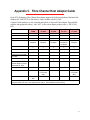
1
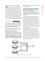
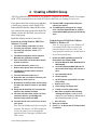
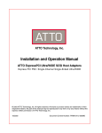
ATTO ExpressRAID
Installation and Operation Manual
RAID Level 0 Software for Windows®
© 2003 ATTO Technology, Inc. All rights reserved. All brand or product names are trademarks of their
respective holders. No part of this manual may be reproduced in any form or by any means without the
express written permission of ATTO Technology, Inc.
7/2003
Document Control Number: PRMA-0123-000MD
Contents
1 RAID Overview
..................................................................................1
RAID Level 0
ATTO ExpressRAID Advantages
2 Installing ExpressRAID ......................................................................3
Installation requirements
ATTO Recommendations
Installation instructions
3 Using ExpressPCI Utilities .................................................................5
4 Creating a RAID 0 Group ....................................................................7
5 Managing RAID Groups ......................................................................9
6 Benchmarking Drives .........................................................................11
7 Troubleshooting ..................................................................................13
Appendix A: Glossary ...........................................................................i
Appendix B: SCSI Host Adapter Selection Guide ...............................iii
Appendix C: Fibre Channel Host Adapter Guide ................................iv
Appendix D: Contact ATTO Technology, Inc. .....................................v
1 RAID Overview
Originally Redundant Array of Inexpensive Disks, now Redundant Array of Independent Drives, RAID is a
storage system using multiple disk drives. ATTO ExpressRAID creates virtual disk arrays on physical drives to
increase capacity and performance.
RAID (Redundant Array of Independent Disks) is a
storage system using multiple disk drives to increase
capacity and performance.
Large amounts of data can be supported over many
smaller drives when the drives are combined into one
large “virtual” drive. Management is easier because,
instead of several drives to consider when deploying
data as in a JBOD (Just a Bunch of Disks)
configuration, the system only has one address or LUN
on a storage bus or network.
RAID overlaps disk seeks, minimizing aggregate seek
time delays for the storage group as a whole. data are
written in equal, short operations to each member of
the RAID group in turn so that when the first member
of a group begins writing to disk, the second member
is available to take data. This continues until the last
member of a group is writing to disk, and the first
member of a group is ready for data.
RAID Level 0
RAID Level 0 is commonly used when performance is
more important than data-protection.
RAID Level 0, also called striping, is accomplished by
mapping data across several disk drives. A single,
larger drive is created from several smaller ones. Data
is stored onto the physical drives in consecutive
“stripes,” defined by the interleave setting in the RAID
application. Files that are larger than the interleave
size are distributed sequentially across the disk drives
in the array. Because data is spread across several
drives, the actual throughput is a function of the
aggregate performance of all the drives in the stripe
group instead of just a single drive. Throughput is
equal to the number of drives times the speed of the
slowest drive in the stripe set.
You should strictly follow a backup policy to protect
data stored on RAID 0 volumes.
ATTO ExpressRAID Advantages
ATTO provides a disk striping method that is
implemented at the HBA driver level. The support
exists in the Windows driver, the BIOS driver and the
DOS driver.
The ATTO disk striping provides the following
features:
❖Supports removable devices
Removable Drives report their presence during any
bus scan as long as they are powered up, even without
media present. Some pseudo-removable drives,
however, do not report their presence unless they are
spun up. Once Windows sees a drive at a particular
bus/ID combination, Disk Manager will always report
that drive as being there.
The ATTO striping code will report all removable
drives to Windows so that all removable drives will
have a drive letter assigned, even when a stripe set is
in the removable drives.
The ATTO striping driver will intercept I/O to any
drive that is a member of an ATTO stripe group. If the
drive is the primary stripe member then the I/O will be
performed against the stripe group. If the drive is not
the primary and it is a removable drive, the ATTO
stripe driver will return an error indicating MEDIA not
available. This mechanism retains the drive mapping
assigned by the initial scan. If the removable media is
replaced with a non-striped set of media the system
will be able to have direct access to the media. The
ATTO striping driver will recognize the fact that media
has changed in removable drives.The driver will then
institute a rescan of all removable drives that it
controls. Any changes to primary drives and stripe
groups will be recorded in the driver. The
reconfiguration of the removable drives is dynamic
and does not require Disk Administrator to be run.
❖Optimizes SCSI requests.
The maximum number of SCSI I/O requests generated
is given by the number of disks in the stripe group
since the HBA driver has access to the scatter gather
information.
For example, to satisfy a 1 megabyte I/O request to a
pair of striped drives with an interleave of 64KB, the
ATTO driver will generate 2 SCSI requests.
1
data will be lost. The stripe group can only be accessed
with a supported driver.
Stripe interleave defines how many logical blocks are
used from one drive in the stripe before the next
drive’s blocks are used. An interleave size of 64KB
(default size) indicates that 64KB of data will come
from one drive and the next 64KB will come from the
next drive. Therefore, performance optimization
attained with striping will only occur when the read or
write command is requesting more than 64KB of data.
The size of the stripe interleave should be matched to
the average size of the read and write commands.
Windows OS RAID cannot vary the interleave from 64
KB, which may not be optimum for your application.
❖An ATTO stripe group is recognized under
BIOS and DOS environments, enabling the
boot drive to be a stripe group.
optimal interleave =
average transfer size
# drives in RAID set
ATTO striping provides interleave sizes from 2KB to
512KB: default is 64KB. The optimum interleave size
is best determined by trial and error. An interleave size
should be chosen and then tested via a benchmark
program or by actual tests of the system.
Generally speaking, the recommended interleave is
equivalent to the average transfer size divided by the
number of drives in the stripe set:
NOTE ATTO ExpressPCI Ultra 320 and
Ultra3/UltraWIDE drivers created before version 1.02 and
1.68, respectively, only supported interleave sizes up to
64KB. If you create a stripe group with an interleave size
greater than 64KB with an unsupported version, the stripe
group will be inaccessible and the driver will report that
members are missing from the stripe group. Do not repair
the stripe group with the RAIDUTIL.EXE program or all
RAID overview
❖Increased interleave size, from 2KB to
512KB
ATTO drivers support striping consistently for all
operating systems by combining drives rather than
partitions.You may boot the system off a striped set of
drives and all operating systems will be able to access
the striped drives.
ATTO drivers support striping at the miniport driver
level in Windows by detecting composite drives
during the initial power-on bus scan. During this scan,
composite drives are reported to the system only on the
last target ID of the stripe group. The miniport driver
intercepts any SCSI command sent to the composite
drive reported on the highest ID and either emulates
the command, sends it to whatever drives in the stripe
group are required to satisfy the request, or rejects it as
an illegal command. Any command sent to one of the
other drives in the stripe set is rejected with a SCSI
Selection Timeout error.
SCSI Inquiry and Read Capacity commands are
emulated. Inquiry data is fabricated to indicate a
manufacturer ID of ATTO and a device ID of whatever
stripe group name was assigned when the group was
created. Read/write/verify requests are sent to the
drives required to satisfy the request based on the disk
address range involved. Commands such as Test Unit
Ready and Prevent/Allow media removal are sent to all
drives in the group. When an error occurs on any or all
drives in a stripe set, the first error which is detected is
returned with the command.
120 GB
Disk Drive
120 GB
Disk Drive
360 GB
Virtual
Stripe Group
ExpressRAID
software presents
one virtual drive
while routing data
to three physical
drives
120 GB
Disk Drive
Example of a 3-drive stripe group created by ExpressRAID
2
2 Installing ExpressRAID
ATTO ExpressRAID supports Windows® NT, 2000 and XP operating systems. Installation requires
basic hardware, the ATTO Technology CD or a download from our website, some basic understandings
of your operating system and some possible adjustments and considerations.
Installation requirements
To successfully install and use your ExpressRAID
software, you will need:
❖One or more ATTO ExpressPCI host
adapters
❖2 or more hard drives
❖Working knowledge of the Microsoft
operating system
❖Microsoft operating system documentation
❖A fully operational computer with all
devices installed and identified, and with
an ExpressPCI host adapter successfully
installed.
❖Your complete ExpressRAID product.
ATTO Recommendations
Where to install ATTO ExpressRAID may be
installed on your desktop or enabled in the ATTO
ExpressPCI host adapter ROM. ATTO
recommends that you install ATTO ExpressRAID
on your desktop for easiest access.
If you plan to boot from a stripe group and there
is a disk error, you may want to install ATTO
ExpressRAID in the host adapter ROM so that
you can delete the stripe group in the ROM. The
desktop version does not allow you to access or
alter an erroneous stripe group.
Note: the procedures to create an ATTO
ExpressRAID level 0 array will differ based
upon whether you are planning to boot from
and install your operating system on the
array, or whether you will be creating an
array for inclusion to a pre-existing fully
operational computer with an operating
system installed.
3 ATTO Technology ExpressRAID for Windows
Although RAID 0 volumes
can be created between different types and models
of drives, use similar types/models to ensure the
access time of the array will be equal to the
average access time of a single drive rather than
the access time for the slowest drive in the array.
Maximum partition size Some operating system
file systems impose maximum partition sizes. For
example, the DOS FAT file systems limits the
maximum partition size to 2 GB, while the
Windows NT FAT file system allows up to a 2
Exabytes partition to be created. Formatting with
NTFS allows much larger partition sizes. It is
important to research the limitations of your
operating system file system before attempting to
create your drive array.
Maximum number of drives A maximum of 32
drives in any one stripe group can be used.
Maximum performance For maximum
performance, use dual channel host adapters with
drives equally distributed across busses.For the
absolute highest performance using SCSI,
connect each of the drives to be striped to a
separate ATTO ExpressPCI SCSI-3 host adapter.
Multiple host adapters increase performance by
allowing data to be transferred to all striped drives
simultaneously.
Third Party SCSI adapters ATTO ExpressRAID
will only function with drives attached to ATTO
ExpressPCI host adapters. Any drives connected
to third party host adapters will not be available
for selection when building array groups through
ATTO ExpressRAID.
DOS prompt for non-Windows systems When
creating and deleting stripe groups for any
operating system other than Windows 2000 or
Drive types/models
Installation instructions
Windows NT, 2000 and XP operating systems
1
Insert the ATTO ExpressRAID CD in the
drive slot of the computer.
2
From the Install pop-up window, select
Continue.
3
Select the continue button in the Directory
pop up window.
4
On the ATTO ExpressRAID Setup screen,
select Continue.
5
Select Continue if you wish to use the default
directory, or change the location, then
select Continue.
6
The installation program will copy the ATTO
ExpressRAID program to the directory you
selected, create a new group to contain all
of the program icons, and create icons for
the utilities and Readme files.
7
Please take a moment to review the Readme
files.
8
Your installation is now complete. See
Chapter 4 for information on how to create
ATTO ExpressRAID arrays for your
operating system.
Installation
Windows NT, you must run all ATTO
ExpressPCI/ATTO ExpressRAID utilities from a
true DOS prompt only, not a DOS window.
Uses Use RAID 0 in environments that demand
high I/O rates such as video production and
editing, image editing, and pre-press.
Digital video If you are using ATTO
ExpressRAID in a digital video environment, you
will want to set your interleave setting to 64K.
You may proceed to perform benchmark testing or
run a test capture to fine tune your interleave
setting.
Upgrading ATTO ExpressRAID To upgrade ATTO
ExpressRAID, you must also update all operating
system and ATTO ExpressPCI drivers and reflash
the ATTO ExpressPCI FC host adapter. The
operating system drivers are an integral part of
ATTO ExpressRAID and are all included on your
ATTO ExpressRAID CD.
Back ups Since RAID 0 does not provide fault
tolerance, establish a backup policy to protect data
stored on RAID 0 volumes.
Note: You do not have to enable ExpressRAID
in the ExpressPCI ROM because it will be
automatically enabled once you have created
the first stripe group.
4
3 Using ExpressPCI Utilities
ATTO ExpressPCI Utilities supports Windows® NT/2000/XP and Windows 95/98. Additional support is
provided through the ATTO hardware BIOS driver (BOOTROM.sys for Ultra3, Ultra/WIDE and Fibre
Channel adapters, BOOTROM2.sys for Ultra320 adapters).
The ExpressPCI Utilities installation utility
will automatically launch when the ATTO
ExpressPCI CD-ROM is inserted.
1
The main installer screen presents four
options. Click on the appropriate button.
Install SCSI Software (ExpressPCI PSC, PSCd,
DC, UL3S, UL3D)
Install SCSI Software (ExpressPCI UL4S,
UL4D)
Install Fibre Channel Software
Exit.
2
Selecting any of the three Install … options
brings up another options window. Some
options may be unavailable, depending on
the type of installation. Click on the
appropriate button to begin the desired
task.
Create Standard Driver Installation Floppy
Create Microsoft Certified Driver Installation
Floppy
Install ATTO Tools
Install Adobe Acrobat
Browse ATTO Manuals
3
Depending on your selection, you will be
presented with additional on-screen
instructions. Follow these instructions to
complete the task. The appropriate utilities
will be installed on your system.
4
Click the Exit button when you are finished
with the installation utility.
5 ATTO Technology ExpressRAID for Windows
ATTO provides a full suite of configuration tools
and supplemental utilities to enhance the
performance of the ExpressPCI host adapters.
❈Host adapter NVRAM settings may be
changed using the appropriate utility. Refer
to ATTO ExpressPCI Utilities Installation
and Operation manual for information on
using these utilities.
During system boot, press [CTRL-F] to modify
NVRAM settings on ExpressPCI Fibre Channel
host adapters
During system boot, press [CTRL-Z] to modify
NVRAM settings on ExpressPCI SCSI host
adapters.
In Windows NT/2000/XP, run the SCSI Util
application to modify NVRAM settings on
ExpressPCI SCSI host adapters.
In Windows 2000/XP, run the ATTO
ExpressPCI Configuration Tool to modify
NVRAM settings on ExpressPCI Ultra 320 SCSI
and Fibre Channel host adapters. This
application does not work with ATTO Ultra3 and
Ultra/WIDE host adapters.
❈Monitoring system performance (Bench32),
configuring mode pages (Alamode),
validating SCSI connections (SCSIDV),
masking Fibre Channel LUNs (LUN Mask)
and other specialized functions are also
supported by ExpressPCI host adapters.
Refer to the appropriate chapter of this
manual for information on these utilities.
6
4 Creating a RAID 0 Group
ATTO ExpressRAID may be installed on your desktop or enabled in the ATTO ExpressPCI host adapter
ROM. ATTO recommends that you install ATTO ExpressRAID on your desktop for easiest use.
If you plan to boot from a stripe group and there
is a disk error, you may want to install ATTO
ExpressRAID in the host adapter ROM so that
you can delete the stripe group in the ROM. The
desktop version does not allow you to access or
alter a stripe group.
15 Exit the RAID Configuration Utility and
reboot your system.
16 The RAID group will appear as a single
drive. Use Disk Administrator to partition
and format the RAID group as you would any
drive.
Install the desktop version for ease of use.
From the an existing Windows 2000/XP or
Windows NT system
1
From the desktop, select the Start icon.
2
From the pop-up menu, select Programs.
3
From the pop-up menu, select ATTO
ExpressRAID.
4
The RAID configuration screen appears.
Maximize the application window.
5
From the ExpressPCI ROM for Windows
2000/XP or Windows NT
Note: If a stripe group or your Windows NT
environment has become corrupted, this
procedure must be used to recover. If the
stripe group has a disk error, you may have to
low level format the drive.
1
Click in the white area of the Stripe Group
window to select it
6
From the Edit menu, select Insert.
7
Enter a stripe group name and click OK.
8
The Members window will be selected
automatically.
9
From the Edit menu select Insert.
Enable the RAID capability in the ATTO
ExpressPCI host adapter ROM
a.
b. Insert ATTO ExpressRAID CD into CD
drive and a blank floppy disk into the a
drive.
c.
e.
11 Repeat step 10 until you have selected all of
the disks you wish to include in your RAID
group.
g. Place floppy into floppy drive.
h. Follow on-screen instructions.
i.
After flash completion the following
message will appear: RAID has been
enabled for your adapter(s). Remember to
Save Parameters when you exit.
j.
Save and exit.
13 From the interleave field, select one of the
interleave sizes for your RAID group.
Choices range from 2 to 512KB.
7 ATTO Technology ExpressRAID for Windows
At ATTO banner press CNTL-F to enter
setup utility.
f. Select Update Flash.
12 Verify that all the disks you have selected
appear in the members window.
Note: Save the RAID group before exiting the
program. The software will NOT prompt you
to save the group if you exit through the
application icon in the upper left hand corner
of the screen.
Run makedisk.bat file.
d. Reboot system.
10 Select the disk you wish to include in your
RAID group, then select OK.
14 From the Group menu, select Save to save
your group.
Boot into Windows 2000, Windows NT or
Windows 9X.
2
Boot your computer
3
Press Ctrl F to launch the ATTO ExpressPCI
FC Utilities.
Main Menu
1. Configure Adapter Channels
2. Selectable Boot Device
3. Reset All Parameters
4. Display Device List
5. Format Disk Drives
6. Configure Stripe Groups
7. Update Flash ROM
8. Save Parameters and Exit
9. Discard Changes and Exit
4
Using the up arrow and down arrow keys, go
to the Configure Stripe Groups option and
press Enter.
5
Press the Insert key to make a stripe group.
6
Enter a group name in that field.
7
Advance to the Interleave field by using the
down arrow key and enter an interleave. The
default value is 65536.
8
Advance to the No Units device field by
using the down arrow key.
9
Press the Insert key for a list of available
disk drives.
10 Select a drive using the up and down arrow
keys and press Enter. The drive will appear
in the Group Members section of the Stripe
Groups window.
11 Repeat steps 5 to 10 to include additional
disk drives in the stripe group.
12 After you have selected all of the drives you
wish to include in your stripe group, press
the Enter key and the stripe group window
appears
Group Members
Group name Number of Units
ATTO RAID
2
Size
Status
17,783,168 OK
13 Press Esc to return to the ATTO ExpressPCI
utilities main menu.
14 Using the up and down arrow keys, go to the
Save Parameters and Exit option and press
Enter.
15 Format and partition the drive as you
normally would.
8
5 Managing RAID Groups
You can create, reconfigure, or delete stripe groups from the Configure Stripe Groups window. Damaged
stripe groups can also be repaired by reconfiguring them, but all data will be lost.
From the Main Menu, highlight Configure Stripe
Groups and press Enter.
You can select an existing stripe group and
reconfigure it by pressing [Enter] or delete it by
pressing [Del]. Pressing [Ins] will take you to a
blank Edit Stripe Group window.
2
When you press [Ins] while in the drive list
on the New/Edit Stripe Group window, the
available drive list appears. All disk drives
not currently members of stripe groups will
be shown.
a.
New/Edit Stripe Group Window
1
[Enter] - Accept group as displayed
a.
When the window first appears, the
cursor will be on the Group Name field.
Enter a unique stripe group name of up
to 32 characters.
b. The Stripe Interleave can be set to 2048,
4096, 8192, 16384, 32768, or 65536
bytes.
c.
If you press the [Enter] key while on this
screen and the stripe group is not valid,
a message box will appear.
d. If there is a blank or non-unique name in
the Group Name field, the cursor will be
placed on this field when you
acknowledge the message box.
e.
If there are fewer than two members in
the stripe group, the cursor will be
placed in the drive list after the message
box is closed.
f. If the stripe group existed before the
configuration utility was started and you
change anything other than the group
name, a warning message will appear
when you press [Enter]. You can decide
to cancel the changes by pressing [n] or
accept the changes by pressing [y].
2
The [Ins] and [Del] keys are not available
(and help text does not appear for them)
until the user goes to the drive list.
3
[Esc] - Exit window, discard changes
Add New Stripe Group Member
1
Select a device and press [Enter] or press
[Esc] to cancel.
9 ATTO Technology ExpressRAID for Windows
If you select a drive which has partitions
defined, a message will warn you when
you try accept the drive into the stripe
group.
b. You may select drives of different sizes
into a stripe group but the total amount
of space in a stripe group is limited to
the number of drives multiplied by the
size of the smallest drive in the group.
Therefore, if you choose to stripe a 2 GB
and a 4 GB drive, the resulting stripe
group will contain only 4 GB, and 2 GB
of disk space will be wasted on the
second drive.
c.
Even if you select drives of exactly the
same size, the total stripe group size
displayed in the Configure Stripe
Groups window may be slightly less
than the sum of the sizes of the drives
because the software must truncate
each drive so that it consists of an
integral number of Stripe Interleaves.
Partition and Format Stripe Groups
Now that you have a stripe group, your system
recognizes the group as a single drive that must be
partitioned and formatted like any other drive.
Windows 2000/Windows NT Use Disk
Administrator to partition the drive as you
normally would partition and format any drive.
For additional help, refer to your operating
system’s instructions.
Windows 95 After building your array groups,
use MS-DOS Fdisk command to prepare your
partitions. Use the format command to initialize
the partition so that it is capable of storing data.
For more help, refer to your operating system’s
instructions.
Deleting an Array
1
2
Press [Esc] to exit to the main menu
3
Choose Save Parameters and Exit for a
system reboot.
To delete an array you have already created,
highlight it in Stripe Group Window and
press [Delete].
10
6 Benchmarking Drives
ExpressRAID includes a utility for benchmarking drives.
Open the ATTO Disk Benchmark by clicking on the
Start button, going to Programs, ATTO Technology
and then clicking on Disk Benchmark.
Status Bar:
❖Displays information or status of the selected
item in the main window.
File:
❖New - Creates a new test document.
❖Open - Opens an existing test document.
❖Save - Saves an opened document using the
same file name.
❖Save As - Saves an opened document to a
specified file name.
❖Resize - Change the size of the window to fit the
dialog.
❖Print - Print the active document.
❖Print Preview - Displays the document as it
would appear printed.
❖Print Setup - Selects a printer and printer
connection.
❖1, 2, 3, 4 - Open previously closed documents.
❖Exit - Ends your Disk Benchmark session.
View:
❖Toolbar - Shows or hides the toolbar.
❖Status Bar - Shows or hides the status bar.
❖Scale Factor - Opens the Scale Factor dialog
box.
Help:
❖Help Topics - Open the Help table of contents.
❖About Bench32 - Display version and
copyright information.
Toolbar:
❖Page icon - Open a new document.
❖Folder icon - Open an existing document.
❖Disk icon - Save the active document with its
current name.
❖Printer icon - Print the active document.
❖Magnifying glass icon - Displays the document
as it would appear printed.
❖Arrows icon - Resize the window to fit the
dialog.
❖Question Mark icon - Display version and
copyright information.
❖Arrow with Question Mark icon - Enter
context sensitive help mode.
11 ATTO Technology ExpressRAID for Windows
Performing a benchmark test:
1
Select the desired test options from the
main window.
Drive
Select the logical drive to benchmark. A test can be
performed on any system drive.
Transfer Size
Select the range of transfer sizes used for reading and
writing data to the test drive. Transfer speeds will be
displayed for each size in the range. If the first size is
greater than the second size, the test will not be
performed for any transfer sizes.
Total Length
Select the total size of the data file to be created on the
test drive. This file is deleted upon completion of
testing.
Direct I/O
If this option is checked, file I/O on the test drive is
performed with no system buffering or caching.
Combine this option with Overlapped I/O for
maximum asynchronous performance.
Radio Button Group
Three additional options are also available -Overlapped I/O, I/O Comparison, and Neither.
Select Overlapped I/O to perform queued I/O. Upon
selection, the Queue Depth option appears to select the
maximum number of read or write commands that
may be executed simultaneously.
Select I/O Comparison to compare the data read from
the test file to the data written on a per block basis. You
can select the data pattern for comparison in the Test
Pattern dropdown box that appears. You can also select
the Run Continuously option to run the test
continuously for a specified number of minutes. The
test will stop before the specified time if any errors are
detected.
Select Neither if you do not want to perform
overlapped I/O or I/O comparisons.
Three additional fields are provided for
informational purposes only:
Actual Value:
The value read from the file.
Stripe Group
Expected Value:
If the test drive is a stripe group, select its name. The
names and quantities of drives in the stripe group will
be printed to the Description box. Select << Clear >>
to clear the contents of the Description box.
The value written to the file.
Controlled by
Lists all ATTO host adapters on the system that may
control the selected drive.
Description
Enter additional information about the test that can be
saved or printed. Be sure to enter additional
information after making a selection from the Stripe
Group dropdown box, as this will erase the current
description.
3
When all selections are made, press the
Start button in the main window. The
benchmark test will now begin on the
selected drive and the Test Results Display
at the bottom of the window will be updated.
The y-axis of the graph represents the
transfer sizes in the selected range and the
x-axis represents the transfer speeds in
MB/sec. I/O speeds for each transfer size are
also displayed textually to the right of the
graph in KB/sec.
4
Pressing the Stop button will stop the test.
5
When the test completes, the results can be
saved or printed.
6
If the I/O comparison option was selected
and errors were not detected, the message
“No errors detected” is displayed.
7
If errors were detected, a dialog box will
appear to display the errors in a table with
the following four columns:
Transfer Size:
Transfer size at which the error occurred.
Buffer Index:
Benchmarking drives
2
Log to File:
Logs the error table to a (*.log) file and closes the
dialog. The file is given the same name as the test file
and saved in the same directory. If the test was not
previously saved, errors are logged to the generic file
Bench32Error.log in the root of the test drive. If the log
file already exists, the new errors are appended to the
previously recorded errors. This is the only way to save
detected errors. They are not saved in the test
document file.
Performing multiple benchmark tests
The ATTO Disk Benchmark supports four command
line parameters for uninterrupted testing:
testfile:
Opens and executes the test named testfile with the
extension.bmk or.tst (prior versions of Disk
Benchmark). If I/O Comparison is selected, errors will
automatically be logged to the appropriate file. Any
other errors that occur during testing are logged to this
file as well.
textfile:
Opens the text file named textfile with the extension
.bmk or .tst (prior versions of Disk Benchmark). Each
test in this list will be opened and executed in order.
Stopping one test in the list will prevent further tests
from being executed. Error logging is the same as with
the command line parameter testfile; however, all
errors generated from all tests in the list are logged to
one file: textfile.log.
/p testfile:
Same as testfile, only the test will be printed to the
default system printer instead of being executed.
/p textfile:
Same as textfile, only the tests in the list will be printed
to the default system printer instead of being executed.
Index into the data block at which the error occurred.
12
7 Troubleshooting
Troubleshooting the installation of any new piece of hardware or software can be frustrating. The
following suggestions may help if you are having problems installing the ATTO ExpressPCI FC host
adapter.
❖Check all cable connections to each device.
Verify that all cables are in proper working
condition.
❖Make sure that each device is powered up
and has completed its self check before
booting your machine.
❖Verify that all devices are functional by
looking at the activity lights on the drive
cases.
❖Reboot your system any time you make
changes to the stripe group.
❖As a last resort, you may use the ATTO boot
configuration utility to low level format a
troublesome device.
❖If you are running Windows NT and the
desktop version of ATTO ExpressRAID
and encounter a corrupt stripe group or
Windows NT failure, you must reboot your
machine and use the ATTO ExpressRAID
installed the ATTO ExpressPCI host
adapter ROM. You cannot alter or modify a
malfunctioning stripe group through the
desktop version of ATTO ExpressRAID.
❖Compare the termination of your system to
the description in the section on
termination in your host adapter manual.
13 ATTO Technology ExpressRAID for Windows
❖Verify that all of the devices attached to the
ExpressPCI host adapter have unique SCSI
IDs. Remember, the ExpressPCI host
adapter has a SCSI ID of 7 by default.
❖If the same device shows up at several
different SCSI IDs, its SCSI ID is probably
set the same as the ExpressPCI host
adapter’s SCSI ID or the cable is defective.
❖Verify the external SCSI devices are all
plugged into an AC outlet, and are turned
on before you power-up your PC.
❖Verify the PCI Bus setup on your
motherboard is configured correctly.
❖If you are installing a SCSI boot drive,
check your CMOS setup and verify that
your DRIVE TYPE is set to NOT
INSTALLED.
❖Have you partitioned your drive, and then
activated that partition?
❖Did you format the drive for your operating
system?
❖If a device does not show up, verify that
cables and termination are set properly or
lengthen the SCSI Bus Reset Delay.
14
Appendix A Glossary
Some common terms used in the storage industry are defined below. More information about Fibre
Channel, SCSI and Storage Area Networks is available through the ATTO Technology website
(www.attotech.com), the Fibre Channel Industry Association (www.fibrechannel.org), the Fibre Channel
Consortium (www.iol.unh.edu/consortiums, click on FC), the SCSI Trade Association (www.scsita.org),
and the Storage Area Networking Industry Association (www.snia.org).
Term
Definition
address
a specific location in memory
ANSI
American National Standards Institute
asynchronous
a method of sending data over a bus in which an initiator sends data then waits for an
acknowledgement (ACK) that the data has been received. See synchronous.
BER
Bit Error Rate: a measure of transmission accuracy; the ratio of bits received in error to bits sent
bit
Smallest unit of data a computer can process: a single binary digit with a value of either 0 or 1
block
a sector of a disk which stores a group of bytes that must be read or written together. Most systems
and hard disks use 512 bytes in a block.
burst speed
maximum speed data can be transferred
Byte
an ordered set of 8 bits
CRC
Cyclic Redundancy Check: an error-correcting code which calculates a numeric value for received
and transmitted data. If no error has occurred during transmission, the CRC for both received and
transmitted data should be the same.
destination
address
a value in the frame header of each frame which identifies the port in the node where the frame is
being sent
FC
Fibre Channel
firmware
Software stored in read-only memory (ROM) or programmable ROM (PROM). Firmware is often
responsible for the behavior of a system when it is first switched on.
frame
an indivisible unit for transfer of information in Fibre Channel
frame header
the first field in the frame containing the address and other control information about the frame.
full duplex
a communication protocol which allows transmission in both directions at the same time
half duplex
a communication protocol which allows transmission in both directions, but only one direction at a
time
host
a processor, usually a CPU and memory, which communicates with devices over an interface
initiator device A component which originates a command
JBOD
Just a Bunch Of Disks: a storage subsystem using multiple independent disk drives with or without
RAID configuration.
LUN
Logical Unit Number: a SCSI or Fibre Channel identifier of a device
originator
an initiating device; a component which originates a command
partition
a logically separate portion of a disk used to allow multiple systems to coexist on a single disk drive.
payload
the part of the data field in a frame left after optional headers are removed
PCI
Peripheral Component Interconnect: a bus which allows devices to communicate with the CPU.
i ATTO Technology ExpressRAID for Windows
Definition
RAID
Originally Redundant Array of Inexpensive Disks, now Redundant Array of Independent Drives: a
storage system spanning multiple disk drives. The following standard RAID specifications will be used
here:
Glossary
Term
RAID 0: disk striping in which fixed-length sequences of data are mapped to member disks in a
regular rotating pattern.
RAID 1: Mirrored arrays: information written to one disk is also written to another simultaneously. Also
known as disk shadowing, real-time copy, and t1 copy.
RAID 10: Striped array with mirroring
receiver
the ultimate destination of data transmission; a terminal device
SCSI
Small Computer Systems Interface: a processor-independent standard for system-level interface
between a computer and intelligent devices including hard disks, floppy disks, CD-ROM, printers,
scanners, etc.
synchronous
a way of sending data over a bus in which an initiator sending data does not wait for an acknowledgement (ACK)
that the data has been received before sending more data. See asynchronous. Both the initiator and receiver
must support synchronous mode.
target
a device which responds to commands by an initiator
topology
logical layout of the parts of a computer system or network and their interconnections
transfer rate
the rate at which bytes or bits are transferred, as in megabytes or gigabits per second.
volume
a usable quantity of storage composed of one or more partitions residing on one or more physical
drives. A standard volume creates a partition on a single drive.
ii
Appendix B SCSI Host Adapter Selection Guide
ATTO Technology offers a number of SCSI and Fibre Channel solutions for storage. The following chart
compares the features of ExpressPCI SCSI host adapters.
Supported platforms: Sun Solaris; Linux; NetWare; SCO Unix; Windows 2000, 95/98, NT, and Macintosh
OS and OS X.
Complete RAID packages are also available and include an ExpressPCI SCSI host adapter, ExpressRAID
software and appropriate cable(s). Add "-KIT" suffix to host adapter product code (i.e. EPCI-UL3D-KIT)
Specific features
Single Channel
ExpressPCI Ultra 320
Express PCI Ultra 3
Express PCI Ultra
Wide
320 MB/sec
160 MB/sec.
40 MB/sec.
64-bit
32-bit
33/66 MHZ
133 MHZ
Bus ID support
30
30
15
EPCI-UL4S
EPCI-UL3S
EPCI-PSC
Max. transfer rate
LVD
HVD
Part number
Dual Channel--- 2
ExpressPCI Ultra 320
independent channels
Max. transfer rate
Express PCI Ultra 3
640 MB/sec
320 MB/sec.
LVD
64-bit
32-bit
33/66 MHZ
133 MHZ
Bus ID support
30
30
EPCI-UL4S
EPCI-UL3D
Part number
iii ATTO Technology ExpressRAID for Windows
Appendix C Fibre Channel Host Adapter Guide
Each ATTO Technology Fibre Channel host adapter supports the following platforms: Macintosh OS,
Windows NT/2000/XP, 95/98, Sun Solaris; Linux; NetWare, and SCO Unix.
Complete RAID packages are also available and include an ExpressPCI host adapter, ExpressRAID
software and appropriate cable(s). Add “-KIT” suffix to host adapter product code (i.e. EPCI-3300KIT).
Fibre Channel ports
Optical interface
ExpressPCI
FCSW
Express PCI
FC 2600
ExpressPCI
FC 3300
ExpressPCI
FC 3321
Express PCI
FC 3305
1
1
1
2
1
Fixed SW LC
Fixed SW LC
Fixed SW SC
Copper interface
HSSDC
HSSDC
Max. transfer rate
200 MB/sec.
full duplex
200 MB/sec.
full duplex
400 MB/sec.
full duplex
400 MB/sec.
per channel
full duplex
400 MB/sec.
full duplex
Class 2 transfers
7
7
7
7
7
7
7
7
7
7
7
7
7
7
7
7
7
7
7
7
7
7
7
7
7
7
7
7
7
7
7
7
7
7
7
500 m
25 m
(175 m with
MIA)
500 m
500 m
25 m
(175 m with
MIA)
Class 3 transfers
Full duplex
66 MHz backward compatible
with 33 MHz
64- and 32-bit PCI support
®
Windows XP/2000/NT;
Windows 95/98; Linux and
Macintosh® OS, OS X
RAID support
Max. cable length
Part number
EPCI-FCSW000
EPCI-2600-000 EPCI-3300-000 EPCI-3321-000 EPCI-3305-000
Complete RAID packages are also available. To receive the ATTO ExpressPCI host adapter, ExpressRAID software and
appropriate cable(s), add “-KIT” to host adapter product code (i.e., EPCI-2600-000-KIT) when ordering.
iv
Appendix D Contact ATTO Technology, Inc.
While we do our best to provide you all the information you will need to use our products, we recognize
that additional assistance is sometime required. If you have questions about installing, using or obtaining
any of our products, you may contact us at:
ATTO Technology, Inc.
155 CrossPoint Parkway
Amherst, NY 14068
The information you need to answer your questions may be available 24-hours a day on our web site
(http://www.attotech.com). You may also contact our support departments at the following e-mail
addresses.
Sales Support:
[email protected]
Technical Support: [email protected]
Telephone customer service and sales support is available Monday through Friday between 8 a.m. and
8 p.m. EST at the following numbers:
(716) 691-1999
(716) 691-9353
voice
fax
v ATTO Technology ExpressRAID for Windows