1
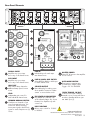
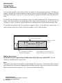
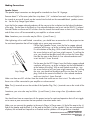
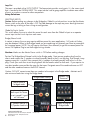
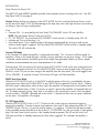
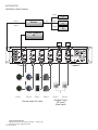
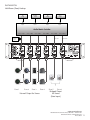
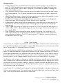
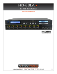
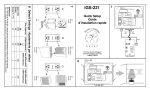
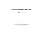
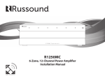
AMP-1270
AMP-870
Instruction Manual
Safety Instructions
1. Read these instructions completely prior to use or hook-up.
2. Keep these instructions for future reference.
3. Understand and heed all Warnings.
4. Follow all instructions.
5. Do not use amp near water.
6. Clean only with a dry cloth. Never use solvents.
7. Do not block any of the ventilation openings.
8. Do not install near heat sources such as stoves, radiators and amplifiers.
9. Do not defeat the safety purpose of the 3 prong grounding plug.
10.
Protect power cord from being walked on or pinched.
11.
Use only connections suggested by manufacturer.
12.
Use only with an approved cart, stand, tripod, bracket or table specified by the manufacturer. When a cart is used, use with caution when moving the cart/apparatus combination to avoid possible injury caused by tipping over.
13.
Unplug this amplifier during lightning storms.
14.
Use an ILS-120 to protect from surges, over/under voltages and lightning strikes.
15.
Refer service to a qualified service personal.
16.
If you install the amplifier in a built-in installation, such as a rack or a bookcase, ensure there is
adequate ventilation. Leave 5” (127mm) of free space at the top and sides and at least 4” (100mm) at the rear.
The exclamation point within an equilateral triangle is intended to alert the
user to the presence of important operation or maintenance instructions.
The lightning flash with arrowhead symbol within an equilateral triangle
is intended to alert the user to the presence of non insulated dangerous
voltages within the product’s enclosure that may be sufficient magnitude
to constitute a risk of electric shock to people.
WARNING
TO REDUCE THE RISK OF
ELECTRIC SHOCK, DO NOT
EXPOSE THIS EQUIPMENT
TO RAIN OR MOISTURE
CAUTION
TO REDUCE THE RISK OF ELECTRIC SHOCK,
DO NOT REMOVE COVER OR BACK. NO
USER-SERVICABLE PARTS INSIDE. REFER TO
QUALIFIED SERVICE PERSONNAL.
This product conforms to all EU Directive
requirements as applicable by law. The
complete Declaration of Conformity can be
found at compliance.currentaudio.com
www.currentaudio.com
2
1890 Cordell Court, Suite 105., El Cajon, CA 92020 • 866-927-7181
©2014 Current Audio - All Rights Reserved.
Rev. 01, 04/14
Thank you for purchasing a Current Audio Multi-Channel Amplifier.
Please read this manual thoroughly before making any connections or applying AC power. This manual
applies to both the AMP-1270 and the AMP-870. The AMP-870 has fewer channels (eight) compared
to the AMP-1270 with twelve channels.
Follow the instructions in this manual. It will allow you to obtain the maximum performance and listening pleasure from your new amplifier.
Please retain this manual to use as a future reference.
Supplied Accessories
The box includes the following equipment and accessories:
• (1) Multi-Channel Digital Amplifier (AMP-1270 or AMP-870).
• (1) Grounded Power Cord for US. Europe uses a 220VAC non grounded cord.
• (1) Set of right angle Rack Mount Brackets
• (1) Instruction Manual
Specifications
Continuous Power
OutputAll channels driven
70 Watts RMS at 4 ohms
50 Watts at 8 ohms
Bridged Power Output
All channels driven
140 Watts per channel RMS at 8 ohms
Caution: Maintain an 8 ohm load in the bridged mode
Standby Power
< 1 watt
Power Consumption
1100 watts
Input Sensitivity/Impedance
500mv /20,000 ohms
Signal to Noise Ratio
95 db
Frequency Response
20 Hz to 20 kHz
Total Harmonic Distortion
(Unabridged or Bridged)
0.1% THD 20 Hz to 20 kHz
Dimensions WxHxD (weight)
17” (431.8mm) x 4” (101.6mm) x 13” (330.2mm)
Glossary of Terms
Amplifier - An electronic device for increasing the amplitude of low level electrical signals, used chiefly in sound
reproduction.
Auto Sensing - Amplifier will only be turned ON when a low level music signal is detected. It will turn off when
no signal is present after about a 10 minute delay. The delay prevents any unwanted annoying cycling of amp.
Bridging - Amplifier bridging is simply using 2 channels of an amplifier to drive a common load for more power.
Channel - This refers to one input or output of a stereo zone.
Continuous Power Out - The ability of an amp to output its full RMS power continuously.
Frequency Response - Range over which an audio component can effectively produce a useable and fairly uniform, undistorted output signal.
Line Level - A low level signal like a CD output that must be amplified to produce a usable audio sound level for
speakers.
Loop Out - A duplicate low level input signal that can be used to power additional amps to expand your zones.
THD - Total Harmonic Distortion; specification that compares the output signal of the amplifier with the input signal and measures the level differences in harmonic frequencies between the two.
Zone - Two channels make one Zone, sometimes referred to as Room in multi-zone/room amplifiers.
www.currentaudio.com
1890 Cordell Court, Suite 105., El Cajon, CA 92020 • 866-927-7181
©2014 Current Audio - All Rights Reserved.
Rev. 01, 04/14
3
Features
•
•
•
•
•
•
•
•
•
•
Dual Power Mode - Input power is switchable from 110VAC to 220VAC.
3 Prong Plug - Grounded input power for Safety.
Master Power Switch - Rear panel switch to cut power for service or hook-up.
Multi-Stage Protection - Each pair of channels/zones is individually protected with internal circuitry
and is indicated on the front bi-color LEDs. The amp will shut down a bad zone if it senses a short
or is overdriven. ONLY the channels that are affected will turn Off and indicates by the LED turning
from blue to red thus pointing to the channel in distress. The remaining zones will run unaffected
and continue to provide sound without shutting down all zones.
Global and/or Individual Inputs - One input signal can be universally distributed to all zones or the
user can individually dedicate one or more zones to have a unique separate input. The other zones
will still play the global input.
Gain Adjustments - There is a global gain control that sets the maximum level to all zones. In addition, each zone has its own separate gain control to allow the user to customize each zone to match
the acoustics of that room. This also sets the maximum loudness of each room.
Installer Friendly Connections - Each speaker channel has pull off plugs to allow the user to make
wire connections up to #14 gauge with positive screw down terminals. The IEC power cord can be
disconnected at the amp for easy service. All inputs are made by easy connect gold plated RCA
plugs.
Bridging - If more power is required for perhaps an outside area, two channels may be combined
(Bridged) to provide 140 watts at 8 ohms. This is accomplished simply by a selector switch at each
zone. CAUTION: Turn power off when making change and always maintain an 8 ohm load when
in the Bridge mode.
Rack Mount - Packed with each amp is an accessory pack that include brackets allowing the amp to
be rack mountable. This is accomplished by attaching the rack ears with the 4 included screws.
Power Mode - Power On has three modes. (1)It can toggled ON/OFF by the front power switch
and is indicated by the corresponding LED. (2)It can also be triggered ON/OFF by a 12 VDC
signal on the rear 3.5mm Trigger in jack. Front Power button must be in standby mode to operate
trigger. LED must be red. The tip of the plug is (+). (3)It can be triggered ON by Music Auto Sense.
In this mode unit will turn OFF after a 10 minuet delay of no signal.
www.currentaudio.com
4
1890 Cordell Court, Suite 105., El Cajon, CA 92020 • 866-927-7181
©2014 Current Audio - All Rights Reserved.
Rev. 01, 04/14
Rear Panel Elements
115/230V
R
GLOBAL
L
MAIN IN
ZONE 1
ZONE 2
ZONE 3
ZONE 4
ZONE 5
ZONE 6
LEVEL
LEVEL
LEVEL
LEVEL
LEVEL
LEVEL
BRIDGED
NORMAL
LOOP
OUT
1
BRIDGED
NORMAL
IN
2
3
BRIDGED
NORMAL
IN
4
5
BRIDGED
NORMAL
IN
6
7
BRIDGED
NORMAL
IN
8
9
MASTER
POWER
ON
50/60Hz 1100W
INPUT
VOLTAGE
115
BRIDGED
NORMAL
IN
10
11
IN
12
OFF
LINE IN
LINE IN
LINE IN
LINE IN
LINE IN
LINE IN
FUSE TYPE:
T10AL 250V FOR 115V
T5AL 250V FOR 230V
AUX IN
MAIN
AUX
SPEAKER
1
2
MAIN
AUX
SPEAKER
3
4
MAIN
AUX
SPEAKER
5
6
MAIN
AUX
SPEAKER
7
8
MAIN
AUX
SPEAKER
9
10
SPEAKER
11
12
MAIN
AUX
LOOP
OUT
CAUTION:
TO REDUCE THE RISK OF FIRE. REPLACE WITH
ONLY THE SAME TYPE AND RATING OF FUSE.
RISQUE DE CHOC ELECTRIQUE.
IN
MUSIC
BRIDGED
BRIDGED
1
BRIDGED
BRIDGED
BRIDGED
4
BRIDGED
9
Model: AMP1270A
Designed in the USA, Built in China
OUT
TRIGGER
DC 12V
ON
Serial No:
WARNING: DO NOT OPEN
RISK OF ELECTRIC SHOCK.
AVIS: NE PAS OUVRIR
ATTENTION:
UTILISER UN FUSIBLE DE RECHANGE DE MEME TYPE.
AUTO
MODE
10
11
5
3
6
2
7
12
13
3
8
1
GLOBAL INPUT
Amplifies any source input
across any or all channel zones.
AUX INPUT
2 Amplifies any source input
across any or all channel zones.
3
LOOP OUT
Amp can be daisy chained to
additional amp inputs for more
zones.
4
LEVEL
Independent gain control for
each individual channel zone.
5
BRIDGED NORMAL SWITCH
Combines two channels of one
zone for increased power. Turn
Power OFF before switching.
Insert same signal to both Line In
inputs for stereo. Requires two (2)
Zones.
6
7
8
9
LINE IN
Individual Input for each separate channel zone.
LINE IN, MAIN, AUX SWITCH
Select LINE IN, MAIN or AUX input
for each channel zone.
MASTER POWER
11 Shuts OFF all power to the amplifier.
Use for service.
12
SPEAKER OUTPUT
Removable plug for making screw
down speaker connections. Make
certain no wire whiskers touch.
IEC POWER-IN CONNECTOR
Plug female IEC cord here. Observe selected voltage. Also houses
the main fuse. Replace only with
correct fuse.
13
AUTO MODE SWITCH
Three ways to energize amp.
Constant ON – MUSIC Sense
Trigger – DC 12V TRIGGER
12VDC TRIGGER IN/OUT
Controls Power state of amp by
external source. Front power button
must be in Standby Mode to operate. Male Tip is (+).
INPUT VOLTAGE
10 Allows user to switch fro 115VAC
to 220VAC.
www.currentaudio.com
1890 Cordell Court, Suite 105., El Cajon, CA 92020 • 866-927-7181
©2014 Current Audio - All Rights Reserved.
Rev. 01, 04/14
5
INSTALLATION
Getting Started
Amplifier Placement
Current Audio amplifiers require plenty of free air space for safe and proper operation. The following
diagram indicates the minimum amount of free air space to provide the proper ventilation and heat
exchange. Anything less than this will shorten the life of the equipment and may cause the amp to shut
down.
Position the amp with all feet on a solid level surface in a well ventilated area. Do not place the unit on
carpet. There are ventilation slots at the bottom that create a natural cooling flow as the heat rises. If
installing in a rack or a cabinet it may be necessary to add a powered fan to provide cooling air flow.
Do not block the ventilation slots. Do not place on carpet or fabric. Do not place near a heat source. In
order to prevent corrosion or electric shock do not place in wet or humid locations.
5” Of free air space at top.
Natural convection
air flow.
4”
AMP 1270/870
NO CARPET
4” of Air Space for ventilation
and cable management.
Allow at least 2” of free air space on
both the left and right sides of the amp.
Making Connections
Caution: All connections and switching should be done with the AC power switched OFF. The final
connection should be the IEC power cord.
Inputs
The inputs on the back of the amplifier are gold plated RCA connectors. Interconnect cables of equal
gold plated quality that are low impedance and shielded should be used to insure a positive continuous
tight connection between equipment. This will insure the total audio quality.
www.currentaudio.com
6
1890 Cordell Court, Suite 105., El Cajon, CA 92020 • 866-927-7181
©2014 Current Audio - All Rights Reserved.
Rev. 01, 04/14
Making Connections
Speaker Outputs
The speaker output connectors are designed for stranded wire from 18-14 gauge.
Remove about 2” of the outer jacket then strip about 1/4” insulation from each wire and slightly twist
the strands to ensure all strands can be inserted into the hole on the removable black speaker connector. See the Strip Gauge figure below.
Insert the Red or copper colored conductor all the way up to the insulation into the hole at the bottom
of the plug. Do the same to the Black or silver colored conductor and insert into the BLACK (-) colored
Terminal. Make sure there are NO whiskers from the strands that could cause a short circuit. The other
end of these wires will be connected to your amplifier or volume control.
Note: Sometimes your wire color may be White (+) and Green (-).
After tightening with a small slotted screwdriver, you should have a connection with the proper tension
for continued operation that will not wiggle out or cause poor connection.
For the Right Speaker Output, insert the Red or copper colored
conductor all the way up to the insulation into the hole labeled
R+ at the bottom of the plug. With a small slotted screwdriver turn
the screw clockwise until you have a tight connect. Try pulling the
wire, you should not be able to pull the wire from the screw plug.
Next do the same to the Black or silver colored conductor and
2”
insert into the R- Screw Terminal.
Do the same for the LEFT Output. Insert the Red or copper colored
conductor all the way up to the insulation into the hole labeled L+
at the bottom of the plug. With a small slotted screwdriver, turn
the screw clockwise until you have a tight connection. Try pulling
Strip Gauge
the wire, you should not be able to pull the wire from the screw
plug. Next do the same to the Black or silver colored conductor
and insert into the L- Screw Terminal.
Make sure there are NO whiskers from the strands that could cause a short circuit. The other end of
these wires will be connected to your amplifier or volume control.
Strip to 1/4”
Note: The (+) terminals are on the outside of the Speaker Plug. The (–) terminals are on the inside of the
plug.
Sometimes your wire color may be White (+) and Green (-) when using a four (4) conductor audio
cable.
You should now have a connection with the proper tension for continued operation that will not wiggle
out or cause a poor connection that can produce intermittent audio static.
Make sure you connect the speakers to the amp In Phase. In Phase means (+) Red of the amp to the (+)
Red of the speaker and the Black (-) of the amp to the Black (-) of the speaker. If they are connected out
of phase, the mid and low frequencies will cancel and the speakers will not perform as intended.
www.currentaudio.com
1890 Cordell Court, Suite 105., El Cajon, CA 92020 • 866-927-7181
©2014 Current Audio - All Rights Reserved.
Rev. 01, 04/14
7
Loop Out
The amp is provided with a LOOP OUTPUT. The loop output provides a unity gain. It is the same signal
that is sourced to the GLOBAL INPUT. This output can be used to gang amplifiers to obtain more zones
of music or used as a source for other components.
Setup Selections
SELECTING INPUTS
Caution: Before making any changes to the Bridged or Global In switch positions insure that the Master
Power switch on the rear of the amp is OFF. Possible damage to the amp may occur due high transient
current during switching or from wiring misconfiguration.
Global In/Line In Switch
This switch allows the user to select the source for each zone from the Global In Input or a separate
source input via the Line In Input on each zone.
Bridge/Mono Switch
In certain instances the user may require addition power for some applications. 140 watts at 8 ohms
may be obtained. When in the Bridged mode you are combining two channels per Zone to accomplish
the increased power. NOTE: You will require two Zones (four channels) to get the increased power for
stereo. Pull Speaker Plug to see the Bridged wiring scheme.
Caution: Make sure the Master Power switch is OFF before making changes.
Position The Bridge-Mono/Normal switch to the Bridge mode. Next remove speaker plug from the
chassis and connect the (-) speaker wire lead (normally black) to the R+ on the plug. Even though it may
appear wrong this is correct. Now connect the (+) speaker wire lead (normally red) to the L+ on the
plug. Check your work then insert the plug back into the female socket for that zone. If you require stereo select another zone and do the same for that zone. Designate one of the combined zones as LEFT
and the other combined zone as the RIGHT channel.
Caution: DO NOT connect more than one speaker to the output in the Bridge mode. Maintain an 8
ohm minimum load when using the Bridge mode.
Bridge Mode Hook-up
Speaker Plug
Removed
Move switch to
bridged mode
Insert same L signal in
both inputs for stereo.
Insert jumped R signal
on 2nd zone.
(-) Speaker Lead to R+
(+) Speaker Lead to L+
www.currentaudio.com
8
1890 Cordell Court, Suite 105., El Cajon, CA 92020 • 866-927-7181
©2014 Current Audio - All Rights Reserved.
Rev. 01, 04/14
Proper Wiring for
Bridge Mode
INSTALLATION
Setup Choices for Power ON
The AMP1270 and AMP870 amplifier provides three separate choices to energize the unit. See #10
Rear Panel Call Out on page 5.
Caution: Before making any changes to the AUTO MODE Switch insure that the Master Power switch
on the rear of the amp is OFF. Possible damage to the amp may occur due high transient current during
switching or from wiring misconfiguration.
It has:
• Constant ON. It is provided by the Front Panel ON/STANDBY Switch. LED must be Blue.
NOTE: The rear Master Power Switch must be ON.
• DC 12V TRIGGER. The Front Panel ON/STANDBY Switch must be in Standby mode. LED will
• indicate red. The tip of the plug is (+).
• Auto Mode Music. In this mode the amp will energize automatically by sensing a small current
when an audio signal is applied. The Front Panel ON/STANDBY Switch must be in Standby mode.
The switch LED will indicate red.
Constant ON Mode
In the Constant ON mode the amplifier is energized continually. This is the most inefficient mode of
operation. When in this mode the amp is always running and does not conserve energy. If this mode
is selected, careful attention should be given to the steady heat generated. Make sure there is ample
ventilation to accommodate the excess heat produced in this mode.
To have power ON constant the ON position of the AUTO MODE Switch on the rear of the panel must
be in the ON location to the left. Turn the MASTER POWER switch on rear of panel to the ON position.
With this switch ON you can now energize the amplifier from the front panel. The switch toggles from
ON to STANDBY. To indicate Constant ON the front LED lights will illuminate Blue.
MUSIC Auto Sense Mode
When the AUTO MODE Switch is in the MUSIC mode the power to the unit is controlled by the input
signal present on either the GLOBAL INPUT or any LINE IN for the separate Channel Zones. When a
low level signal is detected on either of these inputs the amplifier will energize and send speaker level
sound to the selected zones. If after 10 minutes no signal is present the amplifier will automatically turn
off. The delay prevents cycling when there is any pause in the sound/music source. The Front panel
switch must be in STANDBY indicated red on the switch. It should turn Blue when a signal is detected
on the inputs. The amplifier will energize.
DC 12V Trigger Mode
When the AUTO MODE Switch is in DC 12V position the system requires an external trigger to
energize the amplifier. Connect a remote two conductor via a male 3.5mm phone plug to the DC 12V
TRIGGER IN jack. The tip is (+) positive and the sleeve is (-) negative. If more than one device needs
to be controlled connect that device to the to the DC 12V TRIGGER Out jack via a male 3.5mm phone
plug. The front Power Switch must be in the Standby Mode to operate. The LED on the Switch will
illuminate red when in Standby mode and turn Blue when triggered. This indicates the amplifier is
active.
www.currentaudio.com
1890 Cordell Court, Suite 105., El Cajon, CA 92020 • 866-927-7181
©2014 Current Audio - All Rights Reserved.
Rev. 01, 04/14
9
INSTALLATION
Multi-Room (Zone) Hookup
Output
CD
Output
Output
Input
Reciever
Multi-room
Output
Output
Blu-Ray
Output
Output
PC
Output
Source Component
#2
LEFT
RIGHT
115/230V
R
GLOBAL
L
ZONE 1
ZONE 2
LEVEL
MAIN IN
LEVEL
BRIDGED
NORMAL
LOOP
OUT
1
ZONE 3
LEVEL
BRIDGED
NORMAL
IN
2
3
ZONE 4
LEVEL
BRIDGED
NORMAL
IN
4
5
ZONE 5
LEVEL
BRIDGED
NORMAL
IN
6
7
NORMAL
9
INPUT
VOLTAGE
LEVEL
BRIDGED
IN
8
MASTER
POWER
ON
50/60Hz 1100W
ZONE 6
115
BRIDGED
NORMAL
IN
10
11
IN
12
OFF
LINE IN
LINE IN
LINE IN
LINE IN
LINE IN
LINE IN
FUSE TYPE:
T10AL 250V FOR 115V
T5AL 250V FOR 230V
AUX IN
MAIN
AUX
SPEAKER
1
2
MAIN
AUX
SPEAKER
3
4
MAIN
AUX
SPEAKER
5
6
MAIN
AUX
SPEAKER
7
8
MAIN
AUX
SPEAKER
9
10
MAIN
AUX
SPEAKER
11
12
LOOP
OUT
CAUTION:
TO REDUCE THE RISK OF FIRE. REPLACE WITH
ONLY THE SAME TYPE AND RATING OF FUSE.
BRIDGED
Zone 1
BRIDGED
Zone 2
BRIDGED
Zone 3
Normal output for stereo
www.currentaudio.com
10
RISQUE DE CHOC ELECTRIQUE.
IN
MUSIC
TRIGGER
DC 12V
ON
Serial No:
WARNING: DO NOT OPEN
RISK OF ELECTRIC SHOCK.
AVIS: NE PAS OUVRIR
ATTENTION:
UTILISER UN FUSIBLE DE RECHANGE DE MEME TYPE.
1890 Cordell Court, Suite 105., El Cajon, CA 92020 • 866-927-7181
©2014 Current Audio - All Rights Reserved.
Rev. 01, 04/14
BRIDGED
Zone 4
BRIDGED
Zone 5
BRIDGED
Zone 6
Bridged Output
for Stereo
(Note Inputs)
Model: AMP1270A
Designed in the USA, Built in China
AUTO
MODE
OUT
INSTALLATION
Multi-Room (Zone) Hookup
CD
Blu-Ray
PC
Tuner
Output
Output
Output
Output
Input
Input
Input
Input
Audio Matrix Switcher
Zone 1 Out
Zone 2 Out
Zone 3 Out
Zone 4 Out
Zone 5 Out
Individual
Channel
Inputs
Zone 6 Out
LEFT ONLY
RIGHT ONLY
115/230V
R
GLOBAL
L
ZONE 1
ZONE 2
LEVEL
MAIN IN
LEVEL
BRIDGED
NORMAL
LOOP
OUT
1
ZONE 3
LEVEL
BRIDGED
NORMAL
IN
2
3
ZONE 4
LEVEL
BRIDGED
NORMAL
IN
4
5
ZONE 5
LEVEL
BRIDGED
NORMAL
IN
6
7
NORMAL
9
INPUT
VOLTAGE
LEVEL
BRIDGED
IN
8
MASTER
POWER
ON
50/60Hz 1100W
ZONE 6
115
BRIDGED
NORMAL
IN
10
11
IN
12
OFF
LINE IN
LINE IN
LINE IN
LINE IN
LINE IN
LINE IN
FUSE TYPE:
T10AL 250V FOR 115V
T5AL 250V FOR 230V
AUX IN
MAIN
AUX
SPEAKER
1
2
MAIN
AUX
SPEAKER
3
4
MAIN
AUX
SPEAKER
5
6
MAIN
AUX
SPEAKER
7
8
MAIN
AUX
SPEAKER
9
10
MAIN
AUX
SPEAKER
11
12
LOOP
OUT
CAUTION:
TO REDUCE THE RISK OF FIRE. REPLACE WITH
ONLY THE SAME TYPE AND RATING OF FUSE.
RISQUE DE CHOC ELECTRIQUE.
IN
MUSIC
BRIDGED
Zone 1
RISK OF ELECTRIC SHOCK.
AVIS: NE PAS OUVRIR
ATTENTION:
UTILISER UN FUSIBLE DE RECHANGE DE MEME TYPE.
BRIDGED
Zone 2
BRIDGED
Zone 3
Normal Output for Stereo
BRIDGED
Zone 4
BRIDGED
Zone 5
BRIDGED
Model: AMP1270A
Designed in the USA, Built in China
OUT
TRIGGER
DC 12V
ON
Serial No:
WARNING: DO NOT OPEN
AUTO
MODE
Zone 6
Bridged Output
for Stereo
(Note Inputs)
www.currentaudio.com
1890 Cordell Court, Suite 105., El Cajon, CA 92020 • 866-927-7181
©2014 Current Audio - All Rights Reserved.
Rev. 01, 04/14
11
Troubleshooting
Trouble
No Sound From Any
Channel
No Audio from One or
More Channels
No Audio from One
Channel or One Zone
Only
Hum or Buzz
Hum when Receiver/
Source Off
No Audio from Speakers
12 Volt Trigger Not
Working
www.currentaudio.com
12
Possible Cause
Possible Solution
Unit not plugged into AC power
Check power, plug in to a live unswitched
outlet.
Audio cable not properly connected
Check cable connections. Replace cable.
Check if connected to proper inputs.
Matrix Switcher or source
Program amp/matrix switcher to send signal to
your input. Select audio format on DVD.
Master Power Switch on rear of amp
Place Master Power switch to ON.
Front Power Switch
Toggle the Power Switch until the light glows
BLUE. Is 12 Volt Trigger applied?
Source cable may be faulty
Check cable and output from source.
Input Selection switch or Bridge/Normal
switch may be in wrong position.
Verify Normal/Line-In switch is in proper
position. Check Bridge/Normal switch
position. Refer to manual for proper settings.
Speaker Wire or Speaker
Check the speaker connections. Make sure
there are no whiskers that could cause a short.
Any short will cause that zone to shut down
both channels.
Check Front LED Above that Zone
If RED you may have a short or bad speaker.
Measure ohms of wire with speaker plug
out. Should read about 6.5ohms for a 8ohm
speaker. Correct problem- replace wire and/
speaker. If using a manual volume control
check the connections and plug locations.
Switch Speaker Plug with a zone that is
working.
Rear zone Level adjustment turned down
Slowly increase the level clockwise until adequate level is achieved.
Audio cable not properly connected
Check cable connections. Replace cable.
Check if connected to proper inputs
Input Selection Switch or Bridge/Normal
Switch may be in wrong position
Verify Normal/Line-In Switch is in proper
position. Check Bridge/Normal Switch
position. Refer to manual for proper settings.
RCA cable not completely seated.
Push in RCA cables completely. Replace cable.
Bad cable.
Replace cable.
Improper or No ground
Check with a plug tester; Reverse cord; try a 2
prong adapter.
Prewired cable ran too close to AC wires
Insert isolation transformer in-line with RCA
jacks.
Level set too high
Turn rear Level or Global level down.
Cable TV ground not the same as earth
ground
Insert in-line ground isolator.
Ground Loop
Common all grounds, isolate AC ground.
Improper Connection From Amp to Speakers Check speaker wiring at amp to speakers and
from speakers to amp.
Power Switch on front panel
1890 Cordell Court, Suite 105., El Cajon, CA 92020 • 866-927-7181
©2014 Current Audio - All Rights Reserved.
Rev. 01, 04/14
Make sure the Switch is in standby mode
indicated by a RED light. BLUE when triggered.
Considerations:
• Global level setting-start with Global level at zero CCW. Set each zone that is set to Global In to
max CW. With a working known source connected slowly increase the Global Level to the maximum safe listening level. When the amp is energized it will not blast the speakers or damage any
equipment including your ears.
• Using a Volume Control-set volume control to maximum then adjust that zone Level on amp for maximum listening pleasure. This will prevent extra loud volumes on energizing the amp or a particular
zone.
• Adding Zones-If more zones or rooms of music are required you can add an extra amplifier. Use the
unity gain Loop Out to connect to the input of the added amp.
• Blended Stereo-To obtain both Left and Right blended stereo into one speaker use the Bridge technique on one zone. Both Left and Right Preamp channels must be connected.
• Bridged Stereo-To obtain Stereo from two separate zones, jumper both inputs on one zone with the
Left and on the other zone jumper both inputs with the Right. This will provide a true stereo high
powered zone.
• 12VDC Trigger-When using the Trigger jack to control On/Off, wire the tip of the male plug for (+)
12VDC. When 12VDC is present at the Trigger the amp will energize. The front Power Button must
be in standby (RED).
• Surge Protection-To protect the amp from power surges and lightening strikes install the ILS120
in-line surge protector. This will protect the amp from power surges, over and under voltage from
power company and lightning. The ILS120 can be used on TV, subwoofer, computer, projector or
any equipment with an IEC plug.
Limited 1 Year Warranty
Current Audio, LLC amplifiers are warranted to be free from defects in materials and or workmanship to
the original retail purchaser for a period of 1 year, provided the equipment was purchased and installed
from a Current Audio, LLC Authorized Dealer or Distributor.
In the event of defective materials and or workmanship, Current Audio, LLC will repair or replace, at its
option, the defective product at no charge to the purchaser. In order to make claim under this Warranty
and to obtain performance of any obligation under warranty, please contact Current Audio or your Authorized Distributor. Instructions will be given on how to return the defective product to Current Audio.
Returned products must be shipped prepaid. Proof of purchase must be provided with the product.
The Warranty does not apply to damage not resulting from defective materials and or workmanship
while in the possession of the original consumer or due to unreasonable use by the original owner, which
includes but not limited to improper installation, negligence, unauthorized repair or modification, or aesthetic deterioration from the environment. Products purchased by internet or unauthorized sources will
void the warranty and not be honored.
Current Audio, LLC is not liable for any incidental or consequential damages, so the above limitations or
inclusion may not apply to you. This warranty gives you specific legal rights, and you may have other
rights, which vary from state to state within the United States.
www.currentaudio.com
1890 Cordell Court, Suite 105., El Cajon, CA 92020 • 866-927-7181
©2014 Current Audio - All Rights Reserved.
Rev. 01, 04/14
13
1890 Cordell Court, Suite 105., El Cajon, CA 92020 • 866-927-7181
©2014 Current Audio - All Rights Reserved.
www.currentaudio.com
Rev. 01, 04/14