1
Wireless File Transmitter WFT-E7 C Y P O To comply with local radio wave regulations, Canon offers five region-specific versions of the transmitter (WFT-E7A, E7B, E7C, E7D, and E7E) in various areas around the world. (See Areas of Use and Restrictions.) For convenience, we refer to the product in this manual simply as “the transmitter,” without reference to versions A, B, C, D, or E. E INSTRUCTION MANUAL Thank you for purchasing a Canon product. The Wireless File Transmitter WFT-E7 is an accessory for EOS cameras. In addition to time synchronization with other cameras (over a wireless or wired LAN connection) and Bluetooth connectivity with GPS devices, the transmitter enables the following operations. Wireless and Wired LAN Functions FTP Transfer Transfer images to an FTP server EOS Utility Y P O Use EOS Utility to capture, view, and download images remotely C WFT Server Use a web browser to capture, view, and download images remotely Media Server View images on a DLNA-compatible TV or other devices Linked Shooting Wirelessly trigger shooting by slave cameras linked to a master camera 2 Sync the Camera Time over a Wireless or Wired Connection Slave camera Slave camera LAN cable Master camera Slave camera Hub Master camera LAN cable Y P O Master camera Connect to GPS Devices (commercially available) via Bluetooth C Connected via Bluetooth Add the latitude, longitude, altitude, date and time, and other shooting information to images 3 Conventions Used in this Manual These instructions assume that your wireless or wired LAN and FTP server settings are complete. For details on configuring these settings, refer to the documentation provided with the respective equipment. Terms in brackets [ ] indicate button or icon names or other software elements. Brackets also denote camera menu items. The EOS 5D Mark III is used as an example for illustrations and screens in this manual. Note that the screens displayed on your camera may differ, depending on the camera model used. Page numbers in parentheses indicate where you can find additional information. These instructions assume that you have read the Camera Instruction Manual and are familiar with operating the camera. Sections of this manual labeled with the following symbols contain information of the corresponding nature. : Warnings to avoid potential problems are labeled with a caution symbol. : Supplemental information is labeled with a note symbol. C Y P O Windows is a trademark or registered trademark of Microsoft Corporation in the United States and other countries. Macintosh is a registered trademark of Apple Corporation in the United States and other countries. Wi-Fi is a registered trademark of the Wi-Fi Alliance. Wi-Fi Certified, WPA, WPA2, and the Wi-Fi Certified logo are trademarks of the Wi-Fi Alliance. WPS as used on camera settings screens and in this manual signifies Wi-Fi Protected Setup. UPnP is a trademark of the UPnP Implementers Corporation. Bluetooth and the Bluetooth logos are trademarks owned by Bluetooth SIG, Inc. All other corporate and brand names in this manual are trademarks or registered trademarks of their respective owners. Using the transmitter for remote image transfer, capture, or viewing requires adequate knowledge of configuring your wireless or wired LAN and FTP server. Canon cannot provide support for configuring wireless or wired LANs or FTP servers. Note that Canon cannot be held liable for any loss or damage to the transmitter from erroneous network or FTP server settings. In addition, Canon cannot be held liable for any other loss or damage caused by use of the transmitter. 4 Chapter List Introduction 2 1 Basic Network Settings 17 2 Transferring Images to an FTP Server 31 3 Remote Capture Using EOS Utility 47 4 Remote Capture Using WFT Server 53 5 Using the Transmitter as a Media Server 6 Linked Shooting 7 Managing Settings Information 83 8 Synchronizing the Camera Time 89 9 Using Bluetooth GPS Devices 93 10 Troubleshooting 97 11 Reference C Y P O 65 69 113 5 Contents Introduction Conventions Used in this Manual ...................................................................................................... 4 Chapter List........................................................................................................................................ 5 Contents............................................................................................................................................. 6 Safety Warnings................................................................................................................................. 8 Nomenclature..................................................................................................................................... 9 Installing and Removing the Battery ................................................................................................ 11 Using a Household Power Outlet..................................................................................................... 13 Attaching to the Camera .................................................................................................................. 14 Subsequent Organization of This Manual........................................................................................ 16 1 2 3 Basic Network Settings 17 Getting Ready .................................................................................................................................. Displaying the Connection Wizard ................................................................................................... Selecting the Communication Method and LAN Type ..................................................................... Using the Wizard to Establish a Connection.................................................................................... WPS Connections (PBC Mode) ....................................................................................................... WPS Connections (PIN Mode) ........................................................................................................ Configuring Network Settings .......................................................................................................... 18 19 20 23 25 26 27 Transferring Images to an FTP Server 31 Configuring FTP Communication Settings....................................................................................... Automatic Image Transfer After Each Shot ..................................................................................... Transferring Images Individually ...................................................................................................... Batch Transfer ................................................................................................................................. Checking Image Transfer History .................................................................................................... 32 34 37 40 45 Remote Capture Using EOS Utility 47 C Y P O Configuring EOS Utility Communication Settings ............................................................................ 48 Using EOS Utility ............................................................................................................................. 51 4 5 Remote Capture Using WFT Server 53 Configuring WFT Server Communication Settings .......................................................................... Displaying WFT Server .................................................................................................................... Viewing Images................................................................................................................................ Remote Capture [Camera control] ................................................................................................... Remote Capture [Simple control]..................................................................................................... Remote Capture............................................................................................................................... Using WFT Server in Linked Shooting............................................................................................. 54 56 57 59 62 63 64 Using the Transmitter as a Media Server 65 Configuring Media Server Communication Settings ........................................................................ 66 Displaying Captured Images on a Television................................................................................... 67 6 Contents 6 7 Linked Shooting 69 Preparing Slave Cameras................................................................................................................ Basic Linked Shooting ..................................................................................................................... Positioning the Slave Cameras........................................................................................................ Using the Transmitter with WFT Server........................................................................................... 70 71 72 74 Managing Settings Information 83 Checking Settings ............................................................................................................................ 84 Changing Settings............................................................................................................................ 85 Saving and Loading Settings ........................................................................................................... 87 8 Synchronizing the Camera Time 89 Preparing for Time Synchronization................................................................................................. 90 Synchronizing the Time ................................................................................................................... 91 9 Using Bluetooth GPS Devices 93 Connecting GPS Devices via Bluetooth........................................................................................... 94 10 Troubleshooting 97 Y P O Handling Error Messages ................................................................................................................ 98 Wireless LAN Notes....................................................................................................................... 111 Checking Network Settings............................................................................................................ 112 11 Reference C Creating and Registering Captions ................................................................................................ Using a Bracket (Sold Separately)................................................................................................. Specifications................................................................................................................................. Index .............................................................................................................................................. 113 114 115 116 124 7 Safety Warnings The following precautions are intended to prevent harm to you and others as well as damage to equipment. Become familiar with the precautions before using the transmitter to ensure correct and safe operation. Be sure that you fully understand the safety precautions contained in the instruction manuals for the battery, charger, and AC Adapter Kit before using them. Warning Preventing Serious Injury or Death To prevent fire, excessive heat, chemical leakage, or explosion, follow these safety guidelines. • Do not insert metallic objects between electrical contacts of the transmitter, accessories, or connecting cables. Do not use the transmitter where there is flammable gas. There is a risk of explosion or fire. If the transmitter is dropped and internal parts are exposed, do not touch the exposed parts. There is a risk of electrical shock. Do not disassemble or modify the transmitter. High-voltage internal parts may cause electrical shock. Do not store the transmitter in dusty or humid places. There is a risk of fire or electrical shock. Before using the transmitter on board airplanes or in hospitals, make sure use is permitted. Electromagnetic waves emitted by the transmitter may interfere with instrumentation or medical equipment. Caution Preventing Injury or Equipment Damage Do not leave the transmitter inside a vehicle in hot weather or near a heat source. The transmitter may become hot and cause burns if touched. Do not cover or wrap the transmitter with a cloth. This may trap heat inside, posing a risk of case deformation or fire. Do not use paint thinner, benzene, or other organic solvents to clean the transmitter. This poses a risk of fire and may be hazardous to your health. Y P O If the product malfunctions, becomes damaged, or requires repair, contact your dealer or the nearest Canon Service Center. C Handling Precautions The transmitter is a precision instrument. Do not drop it or subject it to shock. The transmitter is not waterproof. Do not use it underwater. Wipe off any moisture with a clean, dry cloth. If the transmitter has been exposed to salty air, wipe it with a clean damp cloth after wringing it out to remove excess water. Never leave the transmitter near any equipment that generates a strong magnetic field, such as magnets or electric motors. Do not leave the transmitter in excessive heat, such as in a vehicle in direct sunlight. High temperature may damage the transmitter. Do not wipe the transmitter using cleaners containing organic solvents. If the transmitter becomes difficult to clean, take it to the nearest Canon Service Center. To avoid corrosion, do not store the transmitter where there are strong chemicals, such as in darkrooms or chemical labs. 8 Nomenclature For detailed information, reference page numbers are provided in parentheses (p.**). Tripod screw Power lamp (p.14) Battery compartment cover release lever (p.11) Battery compartment cover (p.11) <LAN> lamp LCD panel (p.10) Power switch (p.14) C <a> port (p.14) Y P O Ethernet RJ-45 port 9 Nomenclature LCD panel Connection icon Error number Wired LAN connection Wireless signal strength Battery check Bluetooth connection Case Belt holder Strap mounts Case strap C Y P O Case for tripod screw Interface cables Approx. 25 cm / 9.8 in. 10 Approx. 1.5 m / 4.9 ft. Installing and Removing the Battery Use one Battery Pack LP-E6 to power the transmitter. When replacing the transmitter’s battery, be sure to turn the transmitter off before opening the battery compartment cover. Also note that the transmitter is not sold with a battery or charger. If you do not own these accessories, they are available for purchase separately. Installing the battery 1 Open the cover. 2 Insert the battery. 3 Close the cover. Push the lever down and open the cover. Insert the end with the battery contacts. Insert the battery all the way until it locks into place. C Y P O Press the cover up until it clicks into place. 11 Installing and Removing the Battery Battery check The remaining battery power is displayed when you turn the transmitter on. A blinking battery icon ( ) indicates that the battery will be depleted soon. Icon Level (%) 100 – 70 69 – 50 49 – 20 19 – 10 Number of images that can be transferred LAN At Normal Temperature (23°C / 73°F) Wireless LAN 2400 Wired LAN 2200 9–1 0 Approx. number of images At Low Temperature (0°C / 32°F) Y P O 2300 2200 When using a fully charged LP-E6. The number of images that can be transferred is nearly the same at normal temperature (23°C / 73°F) and low temperature (0°C / 32°F). When automatic transfer is performed during shooting of an image of approx. 5 MB under conditions based on the CIPA (Camera & Imaging Products Association) test standards. Fewer images can be transferred when transferring images continuously over a wireless LAN. C Removing the battery 12 1 Open the cover. 2 Remove the battery. Push the lever down and open the cover. Press the battery lock lever in the direction of the arrow to unlock, and then remove the battery. To prevent a short-circuit, be sure to always attach the protective cover to the battery. Using a Household Power Outlet When the AC Adapter Kit ACK-E6 (sold separately) is used, a household power outlet can be used to power the transmitter without worrying about the battery level. 1 Connect the DC coupler plug. 2 Connect the power cord. 3 Insert the DC coupler. Connect the DC coupler plug to the socket of the AC adapter. Connect the power cord as shown. Insert the plug into the outlet. After usage, unplug from the outlet. Y P O Open the cover, and insert the DC coupler firmly until the lock position. 4C Close the cover. Pass the cord through the groove while opening the cap of the DC coupler cord notch, and then close the cover. Do not connect or disconnect the power cord while the transmitter’s power switch is set to <ON>. Do not connect and use AC Adapter Kits ACK-E6 with both the camera and transmitter WFT-E7 simultaneously. It may cause malfunction to the nearby electronic devices. For more information, contact a Canon Service Center. 13 Attaching to the Camera When connecting the transmitter to the camera, always use one of the interface cables included with the transmitter. 1 Turn off both the camera and transmitter. 2 Attach the transmitter’s <a> port cap. 3 Connect the transmitter and camera. To keep the cable securely connected, attach the cap to the transmitter. C 4 Y P O Connect the end of the cable with the <WFT GPS> logo to the transmitter’s <a> terminal. Connect the end of the cable with the <CAMERA> logo to the camera’s <a> terminal. Turn on both the camera and transmitter. X The transmitter’s <3> lamp will light and <D> will be displayed on the transmitter’s LCD panel. Using the Interface Cables Use the 25 cm / 9.8 in. cable when the transmitter is attached to the camera tripod socket or Accessory Bracket AB-E1 (sold separately, p.115). Use the 1.5 m / 4.9 ft. cable when the transmitter is stored in the included case and either worn over your shoulder or attached to a belt. Before disconnecting the cable, turn off both the transmitter and camera. If the transmitter’s <3> lamp blinks, it means that the transmitter and camera are not properly connected. Check the connection. 14 Attaching to the Camera Example of Attachment Y P O Example of Using the Case and Strap C If you turn on/off the transmitter or connect/disconnect the interface cable during Live View shooting or movie shooting, Live View shooting or movie shooting will stop. 15 Subsequent Organization of This Manual Click one of the following chapter titles to view the corresponding page. 1 Basic Network Settings (p.17) 2 Transferring Images to an FTP Server (p.31) 3 Remote Capture Using EOS Utility (p.47) 4 Remote Capture Using WFT Server (p.53) 5 Using the Transmitter as a Media Server (p.65) 6 Linked Shooting Y P O 7 Managing Settings Information C 16 (p.69) (p.83) 8 Synchronizing the Camera Time (p.89) 9 Using Bluetooth GPS Devices (p.93) Basic Network Settings Y P O Complete the basic network settings by following the transmitter’s connection instructions on the camera menu screen. C 17 Getting Ready [FTP trans.], [EOSUtility], [WFTserver] The connection instructions help you follow the steps to connect the transmitter to an existing wireless or wired LAN. To connect to a wireless LAN, prepare the wireless LAN terminal (wireless LAN access point or wireless LAN adapter) and computer in advance so that they are ready for you to connect the transmitter to the wireless network. When configuring the basic network settings, bring the transmitter within 3 m / 9.8 ft. of the wireless LAN terminal. To connect to a wired LAN, use a LAN cable to connect the transmitter and computer. Set the transmitter for connection to the wired network. Wireless transfer of movies Individual movie files are large, and wireless file transfer takes some time. When setting up an environment for stable transmission to the wireless LAN terminal, see the information on page 111. [MediaServ.] Y P O Set up a DLNA*-compatible television, digital photo frame, or similar media player so that it is ready for use after the transmitter is connected to its network. * DLNA: Digital Living Network Alliance [LinkedShot] C Set up multiple cameras, including cameras with this transmitter attached and other cameras compatible with linked shooting that have WFT units attached. 18 Displaying the Connection Wizard This section’s explanation follows the flow of the connection instructions. If an error is displayed, see “Troubleshooting” in Chapter 10 (p.97) and check the settings. Pressing the shutter button or other camera controls during configuration will cause the connection instructions to close. Do not press the shutter button or other controls until configuration is finished. In the menu, set [Auto power off] to [Disable]. If auto power off is activated, the connection instructions close during the configuration process. 1 2 Turn on both the camera and transmitter. 3 Select [Network settings]. Display the transmitter menu. On the camera, press the <7> button. In the menu, select [Communication settings] and press <0>. C 4 Y P O Select [Connection wizard]. X The [Select communication method] screen is displayed. X The <LAN> lamp on the transmitter starts blinking. 19 Selecting the Communication Method and LAN Type Selecting the Communication Method Turn the <5> dial to select the communication method, and then press <0>. Select [OK] and press <0> to go to the next screen. • FTP trans. Select this option to transfer captured images to an FTP server. Images can be automatically transferred as you shoot them, or you can select images to be transferred later. Computer Operating Systems Use of [FTP trans.] requires that one of the following operating systems be installed on your computer. In addition, the computer must be set up as an FTP server in advance. • Windows 7 (Professional, Enterprise, or Ultimate Edition for 32- or 64-bit systems) • Windows Vista (Business, Enterprise, or Ultimate Edition for 32- or 64-bit systems) • Windows XP Professional • Mac OS X 10.6 or 10.7 For instructions on setting up your computer as an FTP server, refer to the computer documentation. The following operating systems cannot be used because FTP server functionality is not provided. • Windows 7 Home Premium • Windows Vista Home Premium/Home Basic Edition • Windows XP Home Edition C Y P O • EOSUtility Select this option for remote capture over a wireless or wired LAN using the EOS Utility software included with your camera. In addition to remote capture, all camera operations in EOS Utility are supported. With this option, a wireless or wired network is used instead of the USB cable. Requires a computer with EOS Utility (software included with EOS digital cameras) installed. 20 Selecting the Communication Method and LAN Type • WFTserver Select this option for remote capture over a wireless or wired LAN with the transmitter acting as a server. Additionally, images on a memory card in the camera can be viewed and downloaded to a computer. The camera can be accessed in the same way as browsing a web page, by users at up to three computers. Computer Operating Systems Any computer with a web browser can be used, regardless of the operating system. Devices other than computers that feature a web browser can also be used. However, if the web browser does not support JavaScript, WFT Server functions will be limited. Also note that devices with limited performance may display images more slowly, and downloading images to these devices may not be possible. • MediaServ. Select this option to view images on a memory card in the camera over a wireless or wired LAN on a television. This function requires a DLNA-compatible television, digital photo frame, or similar media player. • LinkedShot Y P O Select this option for linked shooting, using multiple cameras compatible with linked shooting that have WFT units attached. Up to 10 slave cameras can be linked to the master camera on which you will release the shutter. Note that there will be a slight delay after you release the master camera shutter before the slave cameras shoot. Movie shooting is not supported. For further instructions on [LinkedShot], see page 69 of this manual. C 21 Selecting the Communication Method and LAN Type Selecting the LAN Type For [LinkedShot] instructions, see page 69. Note that no information about [LinkedShot] is given in this chapter. Turn the <5> dial to select the type of LAN, and then press <0>. Select [OK] and press <0> to go to the next screen. Wireless LAN The [Wireless LAN setup method] screen is displayed. [Connect with wizard]: See p.23 [WPS (PBC mode)]: See p.25 [WPS (PIN mode)]: See p.26 Y P O Select [WPS (PBC mode)] or [WPS (PIN mode)] when using a wireless LAN terminal compatible with Wi-Fi Protected Setup (WPS). Wired LAN C The [Network] settings screen is displayed. If you have selected a wired network, see page 27, “Configuring Network Settings.” Use a Category 5e or higher STP LAN cable. (STP: Shielded Twisted Pair) 22 Using the Wizard to Establish a Connection Selecting the Wireless Network When you select [Connect with wizard], active wireless LAN terminals in your area are listed, accompanied by their respective information. Select the SSID (or ESS-ID) of your desired wireless LAN terminal. 1 2 3 4 1 Select [Connect with wizard]. 2 Select the wireless LAN terminal. Turn the <5> dial to select [Connect with wizard], and then press <0>. To select the wireless LAN terminal, press <0>. Turn the <5> dial to select the wireless LAN terminal, and then press <0>. Select [OK] and press <0> to go to the next screen. Y P O 1 Indicates whether the device is in infrastructure or ad hoc mode 2 An icon is displayed if the wireless LAN terminal uses encrypted communication 3 Indicates the first 9 characters of the SSID 4 Indicates the channel used C Encryption by Wireless LAN Terminals If the wireless LAN terminal uses encrypted communication, select the corresponding method in [Authentication] and [Encryption]. [Authentication]: Open system, Shared key, WPA-PSK, or WPA2-PSK [Encryption]: WEP, TKIP, or AES [Enter connection] and [Search again] To configure settings for the wireless LAN terminal manually, select [Enter connection] and press <0>. Complete the settings following the procedure displayed. To search for wireless LAN terminals again, select [Search again] and press <0>. 23 Using the Wizard to Establish a Connection Entering the Wireless LAN Encryption Key Enter the encryption key set for the wireless LAN terminal. For details on the encryption key, refer to the device’s instruction manual. Note that the screens displayed in steps 1 to 3 below vary depending on the authentication and encryption of the wireless LAN terminal. 1 The [Key index] screen is displayed only if WEP encryption is used by the wireless LAN terminal. Turn the <5> dial to select the key index number specified as the access point, and then press <0>. Select [OK] and press <0> to go to the next screen. 2 Turn the <5> dial to select the key format, and then press <0>. Select [OK] and press <0> to go to the next screen. 3 C 24 Y P O Enter the encryption key. To switch between input areas, press the <Q> button. To move the cursor, turn the <5> dial. In the bottom input area, turn the <5> dial and press <0> to enter the encryption key. If you make a mistake, press the <L> button to erase it. When you press the <7> button to complete the connection with the wireless LAN terminal, the [Network] screen (p.27) is displayed. To return to the screen in step 2, press the <6> button. The entry is canceled. WPS Connections (PBC Mode) This is a connection mode when using a wireless LAN terminal compatible with Wi-Fi Protected Setup (WPS). Pushbutton Connection mode (PBC mode) makes it easy to establish a connection between the camera and the wireless LAN terminal by pressing the WPS button on the wireless LAN terminal. Note that if multiple wireless LAN terminals are active in your area, it may be harder to establish a connection. In this case, try using [WPS (PIN mode)] to establish a connection. Confirm the position of the WPS button on the wireless LAN terminal in advance. It may take about one minute to establish connection. Connection may not be possible if stealth functions are enabled on the wireless LAN terminal. Deactivate stealth functions. 1 Select [WPS (PBC mode)]. 2 Establish a connection with the wireless LAN terminal. Turn the <5> dial to select [WPS (PBC mode)], and then press <0>. Select [OK] and press <0> to go to the next screen. C Y P O Press the WPS button on the wireless LAN terminal. For details about where the button is located and how long to press it, refer to the instruction manual of the wireless LAN terminal. Select [OK] and press <0> to establish a connection with the wireless LAN terminal. When the connection with the wireless LAN terminal is established, the [Network] screen (p.27) is displayed. 25 WPS Connections (PIN Mode) This is a connection mode when using a wireless LAN terminal compatible with Wi-Fi Protected Setup (WPS). In PIN code connection mode (PIN mode), an 8-digit identification number specified on the camera is set on the wireless LAN terminal to establish a connection. Even if there are multiple wireless LAN terminals active in your area, this is a relatively reliable method of establishing a connection using a shared identification number. It may take about one minute to establish connection. Connection may not be possible if stealth functions are enabled on the wireless LAN terminal. Deactivate stealth functions. 1 Select [WPS (PIN mode)]. 2 Specify the PIN code on the wireless LAN terminal. Turn the <5> dial to select [WPS (PIN mode)], and then press <0>. Select [OK] and press <0> to go to the next screen. C 3 Y P O On the wireless LAN terminal, specify the 8-digit PIN code shown on camera LCD monitor. For instructions on setting PIN codes on the wireless LAN terminal, refer to the instruction manual of the wireless LAN terminal. Select [OK] and press <0> to display the confirmation screen. Establish a connection with the wireless LAN terminal. 26 Select [OK] and press <0> to establish a connection with the wireless LAN terminal. When the connection with the wireless LAN terminal is established, the [Network] screen (p.27) is displayed. Configuring Network Settings Turn the <5> dial to select a configuration method for the network settings, and then press <0>. Select [OK] and press <0> to go to the next screen. [Auto setting] Settings otherwise configured with [Manual setting] can be configured automatically. However, the IP address and similar settings must be automatically assigned and configured in environments using DHCP servers or wireless LAN terminals or routers supporting DHCP server functions. If an error is displayed, select [Manual setting] regardless of whether the IP address and similar settings are automatically assigned and configured. [Manual setting] The [IP address set.] screen is displayed after you select [Manual setting]. If [Auto setting] results in an error, select [Manual setting]. The IP address you enter must be the IP address assigned to the camera. Enter the [IP address], [Subnet mask], [Gateway], and [DNS address] on each screen as they are displayed. If you are not sure what to enter, see page 112, “Checking Network Settings,” or ask the network administrator or another person knowledgeable about the network. C Y P O When entering numbers for the IP address, subnet mask, and so on, press <0> to move the input position and turn the <5> dial to enter the number. 27 Configuring Network Settings Completing Settings for the Communication Method The following instructions are for setting screens that vary depending on the communication method (FTP Transfer, EOS Utility, WFT Server, or Media Server), as shown below. Read the page that describes the selected communication method. FTP trans. Chapter 2 (p.31) EOSUtility Chapter 3 (p.47) C Y P O Windows 7 and Windows Vista Users Before performing the operations described from page 47, perform the operations below. If these operations are not performed, the WFT Pairing Software described on page 48 may not start. Open the [C Drive] [Program Files] [Canon] [EOS Utility] [WFTPairing] folder (in this order), and then double-click the [WFT FirewallSettings] icon. After performing this operation, perform the operations described from page 47. WFTserver Chapter 4 (p.53) MediaServ. Chapter 5 (p.65) 28 Configuring Network Settings Virtual Keyboard Operation The virtual keyboard is displayed when entering the encryption key, server name, and other information. Switching between input areas To switch between input areas, press the <Q> button. Moving the cursor To move the cursor, turn the <5> dial. You can also move the cursor using <9>. Entering text In the bottom input area, turn the <5> dial to move the cursor and press <0> to enter text. You can also move the cursor using <9>. You can check how many characters you have entered by referring to [*/5] in the upper-right corner of the screen. Y P O Deleting text If you make a mistake, press the <L> button to erase characters. C Confirming entries Press the <7> button to confirm what you have entered and go to the next screen. Canceling entries Press the <6> button to erase the entry and return to the previous screen. 29 C 30 Y P O Transferring Images to an FTP Server Y P O With FTP transfer, you can automatically transfer each image to the FTP server as you shoot or transfer images in batches after shooting. C 31 Configuring FTP Communication Settings These instructions are continued from Chapter 1. 1 Turn the <5> dial to select [Address setting], and then press <0>. 2 If you set the DNS server setting to [Disable], the screen on the left is displayed. Press <0> to select the input position, and then turn the <5> dial to enter the IP address of the FTP server. If you set the DNS server IP address setting to [Auto assign] or [Manual setting], the screen on the left is displayed. For instructions on screen operations, see “Virtual Keyboard Operation” (p.29). Enter the FTP server’s server name or IP address. C 3 32 Y P O In [Port number setting], enter 00021, in most cases. Turn the <5> dial to select [OK], and then press <0> to go to the next screen. 4 Complete the [Passive mode] settings. If an Error 41 (“Cannot connect to FTP server”) is displayed in step 8, setting [Passive mode] to [Enable] may resolve it. 5 Complete the [Proxy server] settings. Turn the <5> dial to select [OK], and then press <0> to go to the next screen. Configuring FTP Communication Settings 6 Complete the [Login method] settings. Turn the <5> dial to select [OK], and then press <0> to go to the next screen. 7 Complete the [Target folder] settings. Select [Root folder] to save images in the root folder as specified in FTP server settings (p.86). Select [Select folder] to specify a subfolder in the root folder. If no folder exists, a folder will be created automatically. Turn the <5> dial to select [OK], and then press <0> to connect to the FTP server. 8 On the confirmation screen displayed next, select [OK] and press <0>. X The <LAN> lamp lights up green. Y P 9 O C Press <0> and turn the <5> dial to select the set number, and then press <0>. Turn the <5> dial to select [OK], and then press <0>. After the connection wizard closes, the display will return to the menu screen. Settings information is stored on the camera. It is not stored on the transmitter. The network settings for FTP transfer are now complete. 33 Automatic Image Transfer After Each Shot An image can be automatically transferred to the FTP server immediately after shooting. You can continue still photo shooting while images are being transferred. Before shooting, be sure to insert a memory card in the camera. If you shoot without recording images, they will not be transferred. Note that automatic transfer of movies is not supported. Transfer movies after shooting, as described on pages 37-44. 1 Select [Communication settings]. 2 3 Select [Network settings]. Y P O Select [Set up]. C 4 Select [Automatic transfer]. 5 Select [Enable]. Take the picture. X The captured images are transferred to the FTP server. During continuous shooting, images are transferred to the FTP server in the order they are captured. The captured images are also stored on the memory card. Any images for which transfer fails or is interrupted will be transferred automatically when the connection is restored (p.36). These images can also be transferred in batches manually at a later time (p.40). 34 Automatic Image Transfer After Each Shot Setting the Size or Type of Images to Transfer With automatic transfer, you can select which images to transfer when recording images of different sizes to CF and SD cards, or when recording both RAW and JPEG images. 1 Select [Communication settings]. 2 3 Select [Network settings]. Select [Set up]. Y P O 4 C Select [Transfer type/size]. 5 Select the size and type of images to transfer. 35 Automatic Image Transfer After Each Shot To transfer smaller JPEGs when the camera is set up to record larger JPEGs to one card and smaller JPEGs to the other, set [JPEG size to trans.] to [Smaller JPEG]. To transfer either RAW or JPEG images when the camera is set up to record RAW images to one card and JPEGs to the other, specify which images to transfer in the [RAW+JPEG transfer] setting. Similarly, complete the same setting when RAW+JPEG images are recorded simultaneously to a single memory card. When images of the same size are recorded to both cards simultaneously, images recorded to the CF card are transferred, regardless of image quality (compression). Auto Retry if Transfer Fails If transfer fails, an error number is displayed on the transmitter’s LCD panel, and the <LAN> lamp blinks in red. In this case, see page 98 to eliminate the cause of the error. Once the cause of the error is eliminated, the images whose transfer previously failed will be transferred automatically. With this option activated, transfer is attempted again automatically after failure, both when shooting with automatic transfer and when transferring captured images via FTP. Note that when you cancel image transfer, or turn off the transmitter or camera, the image will not be re-transferred automatically. See page 40 and transfer the image manually. C Y P O Enabling LAN Power Management In the menu, select [Communication settings] [Network settings] [Set up] [LAN power save]. When this option is set to [Enable], the transmitter will log off from the FTP server after transfer and switch to standby mode. Wireless and wired connectivity will be restored automatically when you attempt to transfer images, and the transmitter will reconnect to the FTP server. 36 Transferring Images Individually Simply select an image and press <0> to transfer it. You can add a caption before transferring the image. You can continue still photo shooting even while images are being transferred. Transferring the Current Image 1 Select [Communication settings]. 2 3 Select [Network settings]. Select [Set up]. C Y P O 4 Select [Transfer with SET]. 5 Select the image. Select [Enable]. Press the <x> button on the camera. Select the image to transfer, and then press <0> to transfer the image. Movies cannot be transferred with this function. If you select a movie and press <0>, the movie playback panel will be displayed. 37 Transferring Images Individually Adding a Caption Before Transfer You can add a registered caption to each image before transfer. This is convenient if you want to inform the recipient of the quantity to print, for example. The caption is also added to images stored on the camera. For instructions on creating and registering captions, see page 114. You can check the captions added to images in the user comments included in the Exif information. 1 2 Take the picture. 3 4 Select [Network settings]. Select [Communication settings]. C Y P O Select [Transfer with caption]. X The last captured image is displayed. It is not possible to select other images on the [Transfer with caption] screen. To select another image for transfer with a caption, play back that image before following these steps. 38 Transferring Images Individually 5 Select a caption. 6 Transfer the image. Turn the <5> dial to select the [Caption] box, and then press <0>. Turn the <5> dial to select the caption content, and then press <0>. C Turn the <5> dial to select [Transfer], and then press <0>. Y P O 39 Batch Transfer After shooting, you can select multiple images as desired and transfer them all at once. You can transfer unsent images or images whose transfer failed previously. You can continue still photo shooting even while images are being transferred. Selecting Images to Transfer 1 In the menu, select [Image transfer]. 2 Select [Image sel./transfer]. 3 Select [Sel.Image]. 4 Select images to transfer. Y P O X An image is displayed. C Press <0> and turn the <5> dial to display <X> in the upper left corner of the images to transfer. Press <0> to confirm your selection. You can select up to 9,999 images. To display three images per screen, hold the <u> button and turn the <6> dial left. To display one image per screen, hold the <u> button and turn the <6> dial right. After selecting images to transfer, press the <7> button. 40 Batch Transfer 5 Transfer the images. Select [Direct transfer]. Select [OK] on the confirmation screen displayed next. X A transfer progress screen is displayed. [RAW+JPEG transfer] Options Selecting [RAW+JPEG transfer] in step 2 on the preceding page will give you the option of transferring RAW images, JPEG images, or both types of images. The options will be the same whether you specify [Sel. Image], [Sel. n], or [All image] as the image selection method. C Y P O Menu Operation During Image Transfer You can use the menu even during image transfer. However, to prevent transfer problems, some menu items are unavailable during transfer, such as [Network settings], [Protect images], [Erase images], [Format card], and [Record func+card/folder sel.]. If you shoot a movie during the image transfer of captured images, the image transfer will be temporary cancelled during movie shooting. 41 Batch Transfer Batch Transfer of Images in a Folder 1 In the menu, select [Image transfer]. 2 3 Select [Image sel./transfer]. 4 Select [Folder images not transfer’d]. 5 Select a folder. Select [Sel.n]. C 42 Y P O To transfer images whose transfer previously failed, select [Folder images failed transf.]. Batch Transfer 6 Transfer the images. Select [Direct transfer]. Select [OK] on the confirmation screen displayed next. X A transfer progress screen is displayed. C Y P O Selecting [Clear folder transf. history] will set the transfer history of images in the selected folder to “unsent.” This enables you to resend all the images in the folder later by selecting [Folder images not transfer’d]. 43 Batch Transfer Batch Transfer of Images on Memory Cards 1 In the menu, select [Image transfer]. 2 3 Select [Image sel./transfer]. 4 Select [Card images not transferred]. 5 Transfer the images. Select [All image]. C Y P O To transfer images whose transfer previously failed, select [Card images failed transfer]. Select [Direct transfer]. Select [OK] on the confirmation screen displayed next. X A transfer progress screen is displayed. Selecting [Clear card’s transf. history] will set the transfer history of images on the memory card to “unsent.” This enables you to resend all the images on the card later by selecting [Card images not transferred]. 44 Checking Image Transfer History Checking the Transfer History of Individual Images To check the transfer history in [Image sel./transfer], select [Sel.Image]. Image not selected for transfer (no mark) Image selected for transfer Image whose transfer failed Y P O Image already transferred C Checking the Transfer History of Memory Cards On the [Image sel./transfer] screen, you can check the number of images to be transferred as well as the transfer history of images in the memory card. Specifically, you can check the number of images classified as [Images failed trans.] and [Images transferred]. 45 C 46 Y P O Remote Capture Using EOS Utility Y P O You can use EOS Utility to shoot remotely over a wireless or wired LAN. As a wireless or wired network is used instead of the USB cable, all camera operations in EOS Utility are supported, in addition to remote capture. C The WFT-E7 wired or wireless LAN functions cannot be used with the Mac version of EOS Utility (as of November 2011). Check the Canon website for the latest system requirements, including supported OS versions. 47 Configuring EOS Utility Communication Settings These instructions are continued from Chapter 1. With EOS Utility, you can use the included WFT Pairing Software to establish a connection between the transmitter and a computer. WFT Pairing Software is installed automatically during easy installation of the software provided with the camera. If it is not installed, install it on the computer that will communicate with the transmitter before this procedure. The configuration procedure below uses Windows 7 as an example. First, the pairing screen is displayed. Turn the <5> dial to select [OK]. When you press <0>, the following message is displayed. ****** represents the last six digits of the MAC address of the transmitter you are connecting. 1 2 C Y P O Start the pairing software. Normally, it is installed in the same location as EOS Utility. X When the pairing software starts up, an icon is displayed in the task bar. X When the camera is detected, a message is displayed. 48 Configuring EOS Utility Communication Settings 3 Double-click the pairing software icon. X Detected cameras are listed. If a camera is already connected, it is not displayed in the list. Click [Connect]. If multiple cameras are displayed, identify the camera to connect to by its [MAC address] or [IP address]. You can check the [MAC address] and [IP address] by accessing [Confirm settings] in the menu (p.84). Y 4 P O C When the camera detects the computer on which you clicked [Connect] in step 3, the message on the left is displayed. Turn the <5> dial to select [OK], and then press <0>. 5 Press <0> and turn the <5> dial to select the set number, and then press <0>. After you turn the <5> dial to select [OK] and press <0>, the connection wizard closes and EOS Utility starts up. X The <LAN> lamp on the transmitter lights up green. Settings information is stored on the camera. It is not stored on the transmitter. The EOS Utility network settings are now complete. 49 Configuring EOS Utility Communication Settings There is no need to complete pairing again if you continue using a particular camera, transmitter, and computer together after pairing without changing the settings. When using this function the next time, simply turn on the camera to which the transmitter is attached and start the pairing software. The connection between the camera and computer will be established automatically. You can add the pairing software to the software launched at startup of your computer. In the [Preferences] [Basic Settings] tab in EOS Utility, select [ Add WFT Pairing Software to the Startup folder]. C 50 Y P O Using EOS Utility For EOS Utility instructions, refer to the Software Instruction Manual (PDF). You can take full advantage of EOS Utility via the transmitter just as via a USB connection, without restrictions. C Y P O In Remote Live View shooting, the rate of image transmission is slower than via USB. The motion of moving subjects cannot be displayed smoothly. 51 C 52 Y P O Remote Capture Using WFT Server Y P O Using a web browser, you can view images recorded on a memory card in the camera and download them to a computer. Additionally, you can shoot remotely over a wireless or wired LAN. Note that bulb, mirror lockup, and movie shooting are not supported. C 53 Configuring WFT Server Communication Settings These instructions are continued from Chapter 1. Press <0> and turn the <5> dial to select the set number, and then press <0>. Press <0> again. After the connection wizard closes, the display will return to the menu screen. X The <LAN> lamp on the transmitter lights up green. Settings information is stored on the camera. It is not stored on the transmitter. Setting up an Account Y P O Enter a login name and password to access the camera from a computer. The login name and password you specify here are used on the computer when connecting to the camera. 1 C 2 54 Turn the <5> dial to select [Set up], and then press <0>. Turn the <5> dial to select [WFT server settings], and then press <0>. Configuring WFT Server Communication Settings 3 Turn the <5> dial to select [WFT account], and then press <0>. When changing the port number, turn the <5> dial to select [Port number] and press <0>. Note that there is normally no need to change the port number (80). 4 Select a user number. With WFT Server, you can connect the camera to up to three computers. Here, select a user number to prevent conflicts when users at other computers are connected to the transmitter simultaneously. Turn the <5> dial to select [User *], and then press <0>. 5 After you select [Login name] and [Password], the following input screen is displayed. For instructions on input screen operations, see “Virtual Keyboard Operation” (p.29). C Y P O The WFT Server network settings are now complete. 55 Displaying WFT Server In the web browser, display WFT Server, a screen for transmitter operations. Make sure you have already established a connection between the camera and computer. 1 2 3 Start the web browser. First, start Internet Explorer or another web browser. Enter the URL. In the address bar, enter the IP address assigned to the camera. Press the <Enter> key. Enter the [Login name] and [Password]. Enter the login name and password as specified in the procedure on page 55. Click [OK] to display the WFT Server screen. Web browsers that support JavaScript will display the screen on the lower left in step 4. Otherwise, a message is displayed when JavaScript is not supported. Choosing not to use JavaScript will display the screen on the lower right in step 4, with limited functions. Y P 4C O Select the language. Select a language at the bottom of the screen. JavaScript supported JavaScript not supported If you don’t know the URL (IP address) You can check the URL (IP address) by accessing [Confirm settings] in the menu (p.84). 56 Viewing Images You can browse the images recorded on the camera’s memory card. 1 Click [Viewer]. 2 Select the memory card. X The image viewing screen is displayed. Click [CF] or [SD]. Click the [DCIM] folder and select the folder containing the images. C 3 Y P O Select an image. To view another image, click the < > buttons or jump to other pages. In JavaScript-compatible web browsers, you can specify how many thumbnails are shown per screen by clicking the pull-down list in the upperright corner of the screen. 57 Viewing Images 4 Download images to the computer. Click a thumbnail. X The image is displayed at a larger size. To download the image to your computer, click < >. Click [Return] to return to the image viewing screen. Y P O Although actual RAW images and movies are not displayed here, they can be downloaded to the computer in the same way as JPEG images. C 58 Remote Capture [Camera control] Set up the camera for Live View shooting beforehand. Note that remote capture of movies is not supported. For web browsers that do not support JavaScript, see page 63, “Remote Capture”. 1 Click [Camera control]. X The advanced capture screen is displayed. ①② ③ ④ ⑲ ⑤⑥ Y P O ⑫ ⑬ ⑭ C ⑯ ⑰ ⑦ ⑧ ⑨ ⑩ ⑪ ⑮ ⑱ ① Battery check ⑪ Quality ② Drive mode ⑫ Shooting mode ③ Number of possible shots ⑬ White balance ④ AF mode ⑭ Metering mode ⑤ Release button ⑮ Menu ⑥ AF/MF switch ⑯ Live View shooting button ⑦ Shutter speed ⑰ Manual focus button ⑧ Aperture ⑱ Live View image size switching button ⑨ ISO speed ⑲ Live View image screen ⑩ Exposure compensation * Items that cannot be set via WFT Server are shaded on the screen. 59 Remote Capture [Camera control] ⑯ ⑱ 2 Set the lens focus mode switch to <f>. 3 Display the Live View image. Click the release button (⑤). When you let go of the button, the camera autofocuses and the picture is taken. With One-Shot AF, the picture is not taken if focus is not achieved. Display the Live View image and focus manually as described in the next steps. Click the Live View shooting button (⑯). X The AF/MF switch (⑥) is set to <g>, and the Live View image is displayed. If the Live View image is not displayed, enable Live View shooting in the menu (⑮). To make the Live View image display more responsive, click the Live View image size switching button (⑱). The Live View image will be displayed at a smaller size, improving responsiveness. To restore the original size, click the button again. Y 4 OP C Manually adjust the focus. Click the buttons < >, < >, < >, < >, < >, and < > to adjust the focus. Note that autofocus is not supported during the Live View image display. To focus more closely, click < >, < >, or < >. To focus farther away, click < >, < >, or < >. Three levels of focus adjustment are available. < >< > : Largest increment < >< > : Intermediate increment < >< > : Smallest increment 60 Remote Capture [Camera control] 5 Configure the shooting functions. 6 Take the picture. Click items such as quality to view and configure their settings. Complete the settings as needed. Click the release button (⑤). When you let go of the button, the picture is taken. X The captured image will be displayed. Captured images are stored on the camera’s memory card. To download images to your computer, see page 57, and use the [Viewer] function. C Y P O The Live View image may freeze when shooting if the camera is accessed by multiple computers. 61 Remote Capture [Simple control] Set up the camera for Live View shooting beforehand. Note that remote capture of movies is not supported. For web browsers that do not support JavaScript, see page 63, “Remote Capture.” 1 Click [Simple control]. X The basic capture screen and the Live View image are displayed. Live View image screen Y P O Manual focus button C Release button 62 < < >< >< >< >< >: Focuses closer >: Focuses farther away Levels of focus adjustment < < < >< >< >< > > > : Largest increment : Intermediate increment : Smallest increment 2 Manually adjust the focus. 3 Take the picture. Set the lens focus mode switch to <f>. Click the buttons < >, < >, < >, < < >, and < > to adjust the focus. >, Click the release button. When you let go of the button, the picture is taken. X The captured image will be displayed. Captured images are stored on the camera’s memory card. To download images to your computer, see page 57, and use the [Viewer] function. Remote Capture The following instructions are for remote capture with web browsers that do not support JavaScript. Set up the camera for Live View shooting beforehand. Note that remote capture of movies is not supported. Screen Release button 1 Click [Capture]. 2 Take the picture. X The capture screen is displayed. The Live View image is not displayed. Set the lens focus mode switch to <g>. Adjust the focus on the camera. Click the release button. When you let go of the button, the picture is taken. X The captured image will be displayed. Captured images are stored on the camera’s memory card. C 3 Y P O Download images to the computer. Click the image. X The image is displayed at a larger size. To download the image to your computer, click < >. Click [Return] to return to the capture screen. Although actual RAW images are not displayed here, they can be downloaded to the computer in the same way as JPEG images. 63 Using WFT Server in Linked Shooting Remote Capture in WFT Server can be used in combination with the transmitter’s “Linked Shooting” function (p.74). Additionally, you can view and download images recorded on the master or slave camera’s memory cards. Linked Shooting Slave camera Slave camera Slave camera C Y P O Master camera WFT Server 64 Slave camera Using the Transmitter as a Media Server Y P O Images on a memory card in the camera can be viewed over a wireless or wired LAN on a television. This function requires a DLNA*-compatible television, digital photo frame, or C similar media player. (Subsequently, this equipment is collectively referred to as the media player.) * DLNA: Digital Living Network Alliance 65 Configuring Media Server Communication Settings These instructions are continued from Chapter 1. Press <0> and turn the <5> dial to select the set number, and then press <0>. Press <0> again. After the connection wizard closes, the display will return to the menu screen. X The <LAN> lamp on the transmitter lights up green. The information you specified is stored on the camera. It is not stored on the transmitter. The media server network settings are now complete. C 66 Y P O Displaying Captured Images on a Television Operate the media player controls to display images recorded on the camera’s memory card on a television. Note that RAW images and movies cannot be displayed. The following operations are performed on the media player. For details, refer to the instruction manual for the media player. 1 Display the media player setting screen on your television. Using the media player functions, display the EOS**> (media server) icon on the television. < A different icon may be displayed, depending on the media player. In that case, locate the icon labeled EOS**. EOS** EOS ** CF 02/28/2012 2 Select the < icon. C 100EOS** 02/28/2012 EOS**> (media server) Selecting the < EOS**> icon will display an icon of the memory card. After you select this icon, you can select folders and images. Select an image to display it at a larger size on the television. For details, refer to the instruction manual for the media player. Y P O 1-100 02/28/2012 IMG_0001.JPG 02/28/2012 IMG_0002.JPG IMG_0003.JPG Information overlay and details displayed on the television vary depending on the media player. Note that depending on the media player, image information may not be displayed. Icons labeled 1-100 (for example) contain images grouped by file number in the selected folder (***EOS**). Date information shown for images is based on the Exif information attached to the images. Date information shown for memory cards or folders may be the current date set on the camera. 67 C 68 Y P O Linked Shooting Y P O With linked shooting, up to 10 slave cameras can be linked in a wireless network to the master camera on which you will release the shutter. Note that there will be a slight delay after you release the master camera C shutter until the slave camera shutters are released. Movie shooting is not supported. Slave camera Master camera 69 Preparing Slave Cameras After setting up the slave cameras as described on this page, follow the steps on the next page for basic linked shooting. For instructions to view or download to your computer the images stored on cameras, see page 74. 1 Select [Communication settings]. 2 3 Select [Network settings]. 4 Select [LinkedShot]. 5 Set up the slave cameras. Select [Connection wizard]. C Y P O Select [Slave]. X The slave cameras are now ready, with the following screen displayed. When using multiple slave cameras, set up all slave cameras to slave state. Once the settings are complete, slaves cannot be added or removed. You must repeat the setup process from step 1. 70 Basic Linked Shooting Shoot with the master camera linked to slave cameras as follows. 1 Set up the master camera. 2 Select [Auto connect]. 3 Set up the slave cameras. Configure the settings on the master camera following steps 1-3 on the preceding page, and then select [Master]. For [Manual connect] instructions, see page 75. Y P O 4 C On the slave cameras, select [OK]. Check the number of slave cameras. X On the master camera LCD monitor, the number of slave cameras detected is displayed. 5 Establish the connection. On the master camera and all slave cameras, select [OK]. X A screen confirming the connection of the camera is displayed. Settings information is stored on the cameras. It is not stored on the transmitters. 71 Positioning the Slave Cameras Slave camera Slave camera Slave camera Slave camera Y P O Master camera C Position the slave cameras in clear view of the master camera, without objects between them. You can position master camera in an overall circumference of up to approximately 100 m / 328 ft. However, the distance supported for linked shooting may be shorter depending on the wireless communication conditions, which are affected by how the cameras are positioned, the environment of use, and weather conditions. Pressing the shutter button halfway on the master camera puts slave cameras in the same state, as if the shutter buttons were pressed halfway. Similarly, fully pressing the shutter button on the master camera has the same effect on slave cameras, which respond as if the shutter buttons were fully pressed. There will be a slight delay after you release the master camera shutter until the slave camera shutters are released. (Simultaneous capture is not possible.) 72 Positioning the Slave Cameras Do not use multiple flash units. Although slight, there is a difference in the shutter release timing which may cause out-of-sync flash firing and inadequate exposure. Linked shooting is not possible when master and slave cameras are set to [Mirror lockup] [Enable] or [Enable:Mirror down w/ s]. During linked shooting, when you press the AE lock or depth-of-field preview button, the camera adjusts the focus and meters as if you had pressed the shutter button halfway. Once you have established a connection between the master camera and slave cameras, the settings are retained even after you replace the batteries. If you will no longer use a slave camera in linked shooting, set [Communication mode] to [Disconnect] on that slave camera. Any cameras compatible with linked shooting, when they have WFT series transmitters attached, can be used as slave cameras, regardless of model. C Y P O 73 Using the Transmitter with WFT Server Using WFT Server, you can shoot remotely with a master camera linked to slave cameras that will shoot at the same time. WFT Server can also be used to access master or slave cameras for the Live View display, and you can adjust the focus and configure remote capture settings as needed. Additionally, images on the camera’s memory cards can be viewed and downloaded. Linked Shooting Slave camera Slave camera Slave camera C Y P O Master camera WFT Server 74 Slave camera Using the Transmitter with WFT Server Connect the Master and Slave Cameras 1 2 Set up the slave cameras. 3 Select [Manual connect]. 4 Select the connection mode. 5 Specify the channel. Set up the slave cameras as described on page 70. Set up the master camera. Complete settings on the master camera following steps 1–3 on page 70, and then select [Master]. C Y P O Select the wireless LAN ad hoc mode supported by the computer. When selecting [Manual setting], specify the same channel on the master camera, slave cameras, and computer. 75 Using the Transmitter with WFT Server 6 Enter the encryption key. 7 Switch to setting up the slave cameras. 8 Check the number of slave cameras. Enter a 5-digit encryption (WEP) key and press the <7> button. The key entered here will be saved on the computer and used to access the master camera from the computer. X On the slave cameras, select [OK]. X On the master camera LCD monitor, the number of slave cameras detected is displayed. Y 9 OP C Establish the connection. On the master camera and all slave cameras, select [OK]. X A screen confirming the connection of the camera is displayed. Settings information is stored on the cameras. It is not stored on the transmitters. 76 Using the Transmitter with WFT Server Check the Camera Settings Check the network settings on the master and slave cameras as follows. Note that without a good understanding of these settings, you cannot access the cameras from a computer. 1 On the master camera, select [Communication settings]. 2 Select [Network settings]. 3 Select [Set up]. Y P 4C O Select [Confirm settings]. X The settings are displayed. 77 Using the Transmitter with WFT Server 5 Check the settings. 6 Check the slave camera settings. Turn the <5> dial to display other screens. Write down the IP address and SSID. C 78 Check network settings on the slave cameras in the same way as you checked the master camera settings. Write down the IP address of all slave cameras. Each camera has a different address. The SSID will be the same as the master camera SSID. Y P O Using the Transmitter with WFT Server Configure WFT Server Communication Settings Enter a login name and password for accessing WFT Server on cameras from a computer. Although you can specify different login names and passwords for each camera, it is also possible to use the same information for all cameras. 1 On the master camera, select [Communication settings]. 2 Select [Network settings]. 3 Select [Set up]. C Y P O 4 Select [WFT server settings]. 5 Select [WFT account]. Note that there is normally no need to change [Port number]. 79 Using the Transmitter with WFT Server 6 Select a user number. 7 Complete the [Login name] and [Password] settings. WFT Server can accept connections from up to three computers per camera. Select a user number to prevent conflicts when users at other computers are connected to the transmitter at the same time. After you select [Login name] and [Password], the following input screen is displayed. For instructions on input screen operations, see “Virtual Keyboard Operation” (p.29). Y P O IP Addresses Assigned to Computers IP addresses assigned to cameras end in 1–11, as in 192.168.1.1–192.168.1.11. For this reason, assign computer IP addresses that end in a number higher than 11, as in 192.168.1.12. C 80 Using the Transmitter with WFT Server Access the Cameras from the Computer To access the cameras from the computer, use the computer’s standard search function to detect wireless LAN terminals. For details, refer to the computer instruction manual. 1 From the computer, find cameras on the network. 2 Connect to a camera. Use built-in searching on the computer to detect wireless LAN terminals. Select a device with the same ID as the SSID you wrote down in steps 5 and 6 on page 78. After the computer requests an encryption (WEP) key, enter the key set in step 6 on page 76. X The computer is now connected to the camera. Display WFT Server 1 2 C 3 Y P O Start a web browser on the computer. First, start Internet Explorer or another web browser. Select the camera to connect to. Enter the IP address you wrote down in steps 5 and 6 on page 78. X The browser now connects to the camera with the IP address you entered. To access a different camera, change the IP address in this step. Complete the [Login name] and [Password] settings. Enter the [Login name] and [Password] as specified in the procedure on page 80. Click [OK] to display the WFT Server screen. 81 Using the Transmitter with WFT Server 4 Select the language. Select a language on the bottom of the screen. Web browsers that support JavaScript will display the screen on the left. A message is displayed when JavaScript is not supported. Selecting not to use JavaScript will display the screen on the right, with limited functions. Y P O View Images on the Camera C See “Viewing Images” on page 57. Images on camera memory cards can be viewed and downloaded. To switch cameras, enter the IP address of the master or slave camera in the web browser. Shoot Remotely See “Remote Capture [Camera control]” on page 59. Remote capture as described on pages 62 and 63 is also possible. To switch cameras, enter the IP address of the master or slave camera in the web browser. You can access slave cameras, adjust the focus and configure shooting functions, and then use the master camera for linked shooting. When shooting remotely with linked shooting, access the master camera. If you connect to a slave camera, only that slave camera will shoot, without linked shooting. 82 Managing Settings Information C Y P O 83 Checking Settings Check the network settings as follows. 1 In [Network settings], select [Set up]. 2 Select [Confirm settings]. X The settings are displayed. Example of FTP transfer and wired LAN settings C 84 Example of FTP transfer and wireless LAN settings Y P O Changing Settings Settings originally completed using the connection wizard can be changed as follows. You can also change IP security settings (IPsec) not completed using the connection wizard, as well as other settings, such as the setting that determines what happens if an image of the same file name as an existing file is sent to the FTP server (p.86). 1 In [Network settings], select [Set up]. 2 Select [LAN settings]. 3 Select the settings number. 4 Select [Change]. 5 Select the item to change. C Y P O Here, select the settings number under which you saved LAN settings. If you select [Change settings name], you can rename and change the settings. Select the desired item from [LAN type], [TCP/IP], [FTP server], or [Wireless LAN], and change the setting. 85 Changing Settings IP Security (IPsec) Configured in [TCP/IP] [Security]. IPsec is a set of standards for encrypted communication over the Internet. It provides effective security for both wireless and wired LANs. To use this function, you must enable IPsec in the network settings of your computer. When IPsec is employed, only transport mode is supported, and 3DES or AES encryption and SHA1 authentication are used. Note that the IP address of the computer for communication with the transmitter must be entered in [Destination address] on the settings screen. Directory Structure of the Target Folder Configured in [FTP server] [Directory structure]. Selecting [Camera] automatically creates a folder structure matching that of the camera’s (such as A/DCIM/100EOS**) in the server’s root folder for image storage. If you have created a subfolder in the root folder by changing the [Target folder] setting, a folder structure such as A/ DCIM/100EOS** is automatically created in that folder for image storage. Selecting [Default] will use the root folder for image storage. If you have created a subfolder in the root folder by changing the [Target folder] setting, images are saved in that folder. Y P O Overwriting Files of the Same Name Configured in [FTP server] [Overwrite same file]. When the transmitter is configured to prevent overwriting C If there is already a file of the same name in the target folder on the FTP server, a suffix consisting of an underscore and a number is appended to the new file’s name. For example: IMG_0003_1.JPG. When you resend images if initial transfer fails Even if the transmitter is configured to overwrite files of the same name, if you resend an image file that could not be transferred initially, the existing file may not be overwritten in some cases. If this happens, a suffix consisting of an underscore, a letter, and a number is appended to the new file’s name. For example: IMG_0003_a1.JPG. Passive Mode Configured in [FTP server] [Passive mode]. Enable this setting in network environments protected by a firewall. If an Error 41 occurs (“Cannot connect to FTP server”), setting passive mode to [Enable] may enable access to the FTP server. Preventing Changes to Settings To prevent accidental changes to LAN settings, set [Protect settings] to [On]. 86 Saving and Loading Settings Network settings can be saved on a memory card for use with other cameras. Saving Settings 1 In [Network settings], select [Set up]. 2 Select [LAN settings]. 3 Select the settings number. Y P O Here, select the settings number under which you saved LAN settings. C 4 Select [Change]. 5 Select [Save settings]. 87 Saving and Loading Settings 6 Select [Save]. X The settings are now saved as a file on the memory card. The settings are saved as a file (WFTNPF**.NIF) in the area of the memory card shown when the card is opened (in the root directory). The file name is determined automatically by the camera: WFTNPF, followed by a number (01 to 99) and the extension NIF. You can rename the file as desired by selecting [Change file name]. Loading Settings Load settings files stored on a memory card as follows. Also use this procedure when loading settings files created on a computer. Make sure the settings file is saved in the folder shown when the memory card is opened (that is, the root directory). 1 Y P O Select [Load settings]. 2C Select the settings file. X Select a settings file that matches your network environment. 3 88 Load the settings file. X Information from the settings file is loaded into the selected settings number. Synchronizing the Camera Time Y P O Set the master camera time on up to 10 slave cameras, as needed. Synchronization can be done over a wireless or wired connection. Note that even after synchronization, there will be a slight margin of error between master and slave camera time of ±0.05 seconds, at most. C 89 Preparing for Time Synchronization Wireless LAN Set up multiple cameras with transmitters attached. Slave camera Master camera Wired LAN Slave camera Y P O Use a LAN cable to connect cameras with transmitters attached. When there are multiple slave cameras, connect them to a hub with LAN cables, and connect the hub to the master camera with a LAN cable. Slave camera LAN cable C Slave camera Hub Master camera LAN cable Master camera 90 Synchronizing the Time Steps 1–5 are the same on master and slave cameras. 1 In the menu, select [Communication settings]. 2 Select [Network settings]. 3 Set [Communication mode] to [Disconnect]. Y P O Once [Communication mode] is set to [Disconnect], you can select [Sync time between cameras]. C 4 Select [Sync time between cameras]. 5 Select [LAN Type]. X Select [OK] on the next screen displayed, shown below. After selecting [Wireless] or [Wired], select [OK]. 91 Synchronizing the Time 6 Set up the master camera. 7 Set up the slave cameras. After configuring the master camera settings following steps 1–5 on the preceding page, select [Master]. X When the next screen is displayed, the master camera is ready. Go to step 7 to set up the slave cameras. After configuring the slave camera settings following steps 1–5 on the preceding page, select [Slave]. X Select [OK] on the next screen displayed, shown below. C 8 Y P O To set the time on multiple slave cameras, follow these steps on each slave camera. The master camera screen shown in step 8 indicates the number of slave cameras. On the master camera, select [OK]. Check the number of slave cameras, and then select [OK]. X The time on slave cameras is now synchronized to the master camera time. Select [OK] to return to the [Network settings] screen. 92 Using Bluetooth GPS Devices Y P O Information including the latitude, longitude, elevation, and date and time can be obtained from commercially-available GPS devices connected via Bluetooth and added to images. The additional information can be checked on the camera as well as by using commercially-available GPS-compatible mapping software. C For a list of specific GPS devices supported, contact the Canon Service Center. For the GPS device instructions, refer to the device’s instruction manual or contact the manufacturer. 93 Connecting GPS Devices via Bluetooth 1 In the menu, select [Communication settings]. 2 Select [Bluetooth device connection]. 3 Once [Communication func] is set to [Enable], you can select [Bluetooth device connection]. X Press <0> when the next screen shown below is displayed. Select the GPS device. C 94 Y P O Nearby active Bluetooth® devices are listed. Turn the <5> dial to select the GPS device, and then press <0>. Select [OK] and press <0>. If a Bluetooth® password has been set on the GPS device, a password input screen is displayed. Enter the password. X The connection between the transmitter and the GPS device starts. It may take a few minutes to establish the connection with the GPS device. Camera operations such as shooting, menu display, or image playback are not possible until the connection is established. Connecting GPS Devices via Bluetooth 4 When the confirmation message is displayed, select [OK]. The GPS connection status changes to [Connected]. Pressing <0> under these conditions will enable you to disconnect the GPS device. While the Bluetooth connection is active, <s> is displayed on the transmitter’s LCD panel and <r> is displayed on the camera’s LCD panel. 5 6 Confirm operation of the GPS device. Make sure the GPS device has determined the current location. Take the picture. C 7 Y P O After confirming that <r> is shown on the camera’s LCD panel, shoot when ready. If the <r> icon is blinking when you shoot, accurate GPS data will not be added to images. Check the GPS data. Play back the image in single image display. Press the <6> button to display the shooting information screen with GPS data. From top to bottom: latitude, longitude, altitude, and Coordinated Universal Time When the camera’s power is turned off and on or when it wakes up from auto power off, do not shoot until the <r> icon remains displayed. If you shoot while the icon is blinking, the correct GPS information may not be added to images. The date and time indicated is the Coordinated Universal Time (UTC) as obtained by the GPS device, which is nearly the same as Greenwich Mean Time (GMT). In some cases, the date and time of the zone specified on the GPS device is indicated. 95 Connecting GPS Devices via Bluetooth Canceling the Bluetooth Connection The Bluetooth connection with the GPS device will not be terminated if you simply turn off the camera. To cancel the connection, follow these steps. 1 In the menu, select [Communication settings]. 2 Select [Bluetooth device connection]. 3 Select [OK]. X Press <0> when the next screen shown below is displayed. Y P O X The Bluetooth connection is canceled. C Select [OK] to return to the [Bluetooth device connection] screen. 96 Troubleshooting C Y P O Transfer speed in ad hoc mode may become extremely slow when the transmitter is used with certain types of computer. For more information, contact your dealer or nearest Canon Service Center. 97 Handling Error Messages If transmitter errors are displayed on the camera LCD monitor, refer to the examples of corrective actions in this section to eliminate the cause of the error. When an error has occurred, the <LAN> lamp on the transmitter blinks and the error number is shown on the LCD panel. The error details can also be checked in the menu, [WFT settings] [Error description]. Click the error number in the following chart to jump to the corresponding page. 11 (p.99) 12 (p.99) 21 (p.99) 22 (p.100) 23 (p.100) 24 (p.101) 25 (p.102) 41 (p.103) 42 (p.104) 43 (p.104) 44 (p.104) 45 (p.105) 46 (p.105) 47 (p.106) 51 (p.106) 52 (p.106) 53 (p.106) 54 (p.106) 61 (p.107) 62 (p.107) 63 (p.108) 64 (p.108) 66 (p.109) 67 (p.109) 68 (p.109) 69 (p.109) 71 (p.110) 72 (p.110) 73 (p.110) 26 (p.102) 81 (p.110) 91 (p.110) 65 (p.108) Y P O When the error below is displayed When “ERROR 01” is displayed on the WFT-E7 LCD panel, firmly reconnect the camera and the WFT-E7 with the interface cable. C * This error is not displayed on the camera LCD monitor. * This error is also displayed when the WFT-E7 is connected to a camera not compatible with the WFT-E7. If [Waiting to retry transfer…] is displayed If image transfer via FTP fails after shooting, the screen on the left is displayed. Also, an error number is displayed on the transmitter’s LCD panel, and the <LAN> lamp blinks in red. Check the error number and eliminate the cause of the error. Once the cause of the error is eliminated, the images whose transfer previously failed will be transferred automatically. Note that if you cancel image transfer or turn off the camera, auto retry is not performed. Follow the steps on page 40 to transfer the images. 98 Handling Error Messages 11: Connection target not found Is the pairing software running? X Start the pairing software and follow the instructions to re-establish the connection (p.48). Are the transmitter and wireless LAN terminal configured with the same encryption key for authentication? X This error occurs if the encryption keys do not match when the authentication method for encryption is [Open system]. The setting is case-sensitive, so check upper- and lower-case characters. Make sure the correct encryption key for authentication is entered on the transmitter (p.24). 12: Connection target not found Are the target computer and wireless LAN terminal on? X Turn on the target computer and wireless LAN terminal. 21: No address assigned by DHCP server What to check on the transmitter Y P O Is the transmitter’s network setting set to [Auto setting], or its IP address setting set to [Auto assign]? X If you are not using a DHCP server, set the transmitter’s network setting to [Manual setting] and IP address setting to [Manual setting] (p.27). C What to check on the DHCP server Is the DHCP server on? X Turn the DHCP server on. Are there enough addresses for assignment by the DHCP server? X Increase the number of addresses assigned by the DHCP server. X Remove devices assigned addresses by the DHCP server from the network to reduce the number of addresses in use. Is the DHCP server functioning correctly? X Check the DHCP server settings to make sure it is functioning correctly as a DHCP server. X If applicable, ask your network administrator to ensure that the DHCP server can be used. Handling Error Messages 21 - 26 Check the following points when responding to errors numbered 21 - 26. Are the transmitter and wireless LAN terminal configured with the same encryption key for authentication? X This error occurs if the encryption keys do not match when the authentication method for encryption is [Open system]. The setting is case-sensitive, so check upper- and lower-case characters. Make sure the correct encryption key for authentication is entered on the transmitter (p.24). 99 Handling Error Messages 22: No response from DNS server What to check on the transmitter Is the transmitter’s DNS address setting set to [Auto assign] or [Manual setting]? X If you are not using a DNS server, set the transmitter’s DNS address setting to [Disable] (p.27). On the transmitter, does the DNS server’s IP address setting match the server’s actual address? X Configure the IP address on the transmitter to match the actual DNS server address (p.27, 112). What to check on the DNS server Is the DNS server on? X Turn the DNS server on. Are the DNS server settings for IP addresses and the corresponding names correct? X On the DNS server, make sure IP addresses and the corresponding names are entered correctly. Y P O Is the DNS server functioning correctly? X Check the DNS server settings to make sure the server is functioning correctly as a DNS server. X If applicable, ask your network administrator to ensure that the DNS server can be used. What to check on the network as a whole C Does your network include a router or similar device that serves as a gateway? X If applicable, ask your network administrator for the network gateway address and enter it on the transmitter (p.27, 112). X Make sure the gateway address setting is correctly entered on all network devices, including the transmitter. 23: Duplicate IP address What to check on the transmitter Is another device on the transmitter network using the same IP address as the transmitter? X Change the transmitter’s IP address to avoid using the same address as another device on the network. Otherwise, change the IP address of the device that has a redundant address. X In network environments with a DHCP server, if the transmitter’s IP address setting is [Manual setting], change it to [Auto assign] (p.27). 100 Handling Error Messages 24: No response from proxy server What to check on the transmitter The transmitter’s proxy server setting is [Enable]. Does the error occur under this setting? X If you are not using a proxy server, set the transmitter’s proxy server setting to [Disable] (p.32). Do the transmitter’s [Address setting] and [Port No.] settings match those of the proxy server? X Configure the transmitter’s proxy server address and port number to match those of the proxy server (p.32). In the transmitter’s [Proxy server] settings, have you only entered [Server name]? X If the proxy server’s [Address] setting is not configured on the transmitter, enter it along with the DNS server address (p.27). Make sure the server name and port number for the proxy server are entered correctly (p.32). What to check on the proxy server Is the proxy server on? X Turn the proxy server on. Y P O Is the proxy server functioning correctly? X Check the proxy server settings to make sure the server is functioning correctly as a proxy server. X If applicable, ask your network administrator for the proxy server address or server name and port number, and then enter them on the transmitter. C What to check on the network as a whole Does your network include a router or similar device that serves as a gateway? X If applicable, ask your network administrator for the network gateway address and enter it on the transmitter. X Make sure the gateway address setting is correctly entered on all network devices, including the transmitter. 101 Handling Error Messages 25: Another terminal has set the same IP address Is another device on the transmitter network using the same IP address as the transmitter? X This error occurs if the transmitter is connected to a network where another device subsequently connects with the same IP address. Change the transmitter’s IP address to avoid using the same address as another device on the network. Otherwise, change the IP address of the device that has a redundant address. 26: No response from DHCP server What to check on the transmitter On the transmitter, the network setting is [Auto setting]. Does the error occur under this setting? X If you are not using a DHCP server, set the transmitter’s network setting to [Manual setting] (p.27). What to check on the DHCP server Is the DHCP server on? X Turn the DHCP server on. Y P O Are the DHCP server settings for IP addresses and the corresponding names correct? X On the DHCP server, make sure IP addresses and the corresponding names are entered correctly. C Is the DHCP server functioning correctly? X Check the DHCP server settings to make sure it is functioning correctly as a DHCP server. X If applicable, ask your network administrator to ensure that the DHCP server can be used. What to check on the network as a whole Does your network include a router or similar device that serves as a gateway? X If applicable, ask your network administrator for the network gateway address and enter it on the transmitter (p.27). X Make sure the gateway address setting is correctly entered on all network devices, including the transmitter. 102 Handling Error Messages 41: Cannot connect to FTP server What to check on the transmitter On the transmitter, does the FTP server’s IP address setting match the server’s actual address? X Configure the IP address on the transmitter to match the actual FTP server address (p.32). Are the transmitter and wireless LAN terminal configured with the same encryption key for authentication? X This error occurs if the encryption keys do not match when the authentication method for encryption is [Open system]. The setting is case-sensitive, so check upper- and lower-case characters. Make sure the correct encryption key for authentication is entered on the transmitter (p.24). On the transmitter, does the [Port number setting] for the FTP server match the actual port number of the FTP server? X Configure the same port number (usually 21) on the transmitter and FTP server. Configure the port number on the transmitter to match the actual FTP server port number (p.32). Y P O If only the FTP server’s [Server name] is configured on the transmitter, are the DNS server settings complete? X If the FTP server’s [Address] setting is not configured on the transmitter, enable use of the DNS server on the transmitter and enter its address (p.27). Make sure the FTP server name is entered correctly (p.32). C What to check on the FTP server Is the FTP server functioning correctly? X Configure the computer correctly to function as an FTP server. X If applicable, ask your network administrator for the FTP server address and port number, and then enter them on the transmitter. Is the FTP server on? X Turn the FTP server on. The server may have been turned off because of an energysaving mode. On the transmitter, does the FTP server’s IP address setting (in [Address]) match the server’s actual address? X Configure the IP address on the transmitter to match the actual FTP server address (p.32). Is a firewall or other security software enabled? X Some security software uses a firewall to restrict access to the FTP server. Change the firewall settings to allow access to the FTP server. X You may be able to access the FTP server by setting [Passive mode] to [Enable] on the transmitter (p.86). 103 Handling Error Messages Are you connecting to the FTP server via a broadband router? X Some broadband routers use a firewall to restrict access to the FTP server. Change the firewall settings to allow access to the FTP server. X You may be able to access the FTP server by setting [Passive mode] to [Enable] on the transmitter (p.86). If you are using Windows XP Service Pack 2 or later, is access to the FTP server blocked by [Windows Firewall]? X Change the Windows Firewall settings to allow access to the FTP server. What to check on the network as a whole Does your network include a router or similar device that serves as a gateway? X If applicable, ask your network administrator for the network gateway address and enter it on the transmitter (p.27). X Make sure the gateway address setting is correctly entered on all network devices, including the transmitter. 42: FTP server rejected connection What to check on the FTP server Y P O Is the FTP server configured to restrict access to only some IP addresses? X Change the FTP server settings to allow access from the [IP address] configured on the transmitter in the TCP/IP settings. 43: Cannot connect to FTP server. Error code received from server. C What to check on the FTP server Have you exceeded the maximum number of FTP server connections? X Disconnect some network devices from the FTP server or increase the maximum number of connections. 44: Cannot disconnect FTP server. Error code received from server. This error occurs if the transmitter fails to disconnect from the FTP server for some reason. X Turn the FTP server and camera off and on. 104 Handling Error Messages 45: Cannot login to FTP server. Error code received from server. What to check on the transmitter On the transmitter, is the [Login name] entered correctly? X Check the login name for accessing the FTP server. The setting is case-sensitive, so check upper- and lower-case characters. Make sure the correct login name is entered on the transmitter (p.33). On the transmitter, is the [Login password] entered correctly? X If a login password is configured on the FTP server, check the upper- and lower-case characters to make sure the password on the transmitter matches it (p.33). What to check on the FTP server Do the user rights for the FTP server allow reading, writing, and log access? X Configure the FTP server’s user rights to allow reading, writing, and log access. Is the folder specified as the transfer destination on the FTP server named with ASCII characters (p.29)? X Use ASCII characters for the folder name. Y P O 46: For the data session, error code received from FTP server What to check on the FTP server The connection was terminated by the FTP server. X Restart the FTP server. C Do the user rights for the FTP server allow reading, writing, and log access? X Configure the FTP server’s user rights to allow reading, writing, and log access. Do user rights allow access to the target folder on the FTP server? X Configure the user rights for access to the target folder on the FTP server to allow saving images from the transmitter. Is the FTP server on? X Turn the FTP server on. The server may have been turned off because of an energysaving mode. Is the hard disk of the FTP server full? X Increase available space on the hard disk. 105 Handling Error Messages 47: Image file transfer completion not confirmed by FTP server This error occurs if, for some reason, the transmitter fails to receive confirmation from the FTP server that image file transfer is complete. X Turn the FTP server and camera off and on and send the images again. 51: Connection to Bluetooth device lost Is the Bluetooth unit too far from the GPS device? X Bring the GPS device closer to the Bluetooth unit. Are any obstacles blocking the line of sight between the Bluetooth unit and the GPS device? X Move the GPS device to a position visible from the point of view of the Bluetooth unit. The Bluetooth unit and GPS device were disconnected, for some reason, and the connection cannot be restored. X The connection is more likely to be lost if there are nearby wireless LAN terminals, cordless telephones, microphones, microwave ovens, or similar devices operating on the same 2.4 GHz band used for Bluetooth communication. Also note that the connection is more likely to be lost in poor weather or high humidity. Is the GPS device on? X Turn the GPS device on. Y P O 52: Bluetooth device cannot be found C Is the GPS device ready for the Bluetooth connection? X Turn the GPS device on and set it up for connection via Bluetooth. Is the Bluetooth unit too far from the GPS device? X Bring the GPS device closer to the Bluetooth unit. Is the GPS device on? X Turn the GPS device on. 53: Incorrect Bluetooth password Is the same password set on the Bluetooth unit and GPS device? X The setting is case-sensitive, so check upper- and lower-case characters. Make sure the correct password is entered on the GPS device and Bluetooth unit. 54: No compatible Bluetooth service available on connected device The GPS device does not support SPP (Serial Port Profile). X Confirm that the GPS device supports SPP. 106 Handling Error Messages 61: Selected SSID wireless LAN network not found Are any obstacles blocking the line of sight between the transmitter and the antenna of the wireless LAN terminal? X Move the antenna to a position clearly visible from the point of view of the transmitter (p.111). What to check on the transmitter On the transmitter, does the SSID setting match that of the wireless LAN terminal? X Check the SSID on the wireless LAN terminal, and configure the same SSID on the transmitter (p.23). What to check on the wireless LAN terminal Is the wireless LAN terminal on? X Turn on the wireless LAN terminal. If you are filtering by MAC address, did you register the transmitter’s MAC address on the wireless LAN terminal? X Register the transmitter’s MAC address (p.84) on the wireless LAN terminal. Y P O 62: No response from wireless LAN terminal What to check on the transmitter Is the transmitter configured for communication in infrastructure mode? X Configure the transmitter for communication in ad hoc mode. C What to check on the wireless LAN terminal Is there a nearby wireless LAN terminal for ad hoc communication? X Prepare a wireless LAN terminal for ad hoc communication near the transmitter. 107 Handling Error Messages 63: Wireless LAN authentication failed Are the transmitter and wireless LAN terminal configured for the same authentication method? X The transmitter supports these authentication methods: [Open system], [Shared key], [WPA-PSK], and [WPA2-PSK] (p.23). X When using an AirPort for communication in infrastructure mode, [Open system] is not supported. Configure a [Shared key] on the transmitter (p.23). Are the transmitter and wireless LAN terminal configured with the same encryption key for authentication? X The setting is case-sensitive, so check upper- and lower-case characters. Make sure the correct encryption key for authentication is entered on the transmitter and wireless LAN terminal (p.24). If you are filtering by MAC address, did you register the transmitter’s MAC address on the wireless LAN terminal? X Register the transmitter’s MAC address (p.84) on the wireless LAN terminal. 64: Cannot connect to wireless LAN terminal Y P O Are the transmitter and wireless LAN terminal configured for the same encryption method? X The transmitter supports these encryption methods: [WEP], [TKIP], and [AES] (p.23). If you are filtering by MAC address, did you register the transmitter’s MAC address on the wireless LAN terminal? X Register the transmitter’s MAC address (p.84) on the wireless LAN terminal. C 65: Wireless LAN connection lost Are any obstacles blocking the line of sight between the transmitter and the antenna of the wireless LAN terminal? X Move the antenna to a position clearly visible from the point of view of the transmitter (p.111). The wireless LAN connection was lost, for some reason, and the connection cannot be restored. X The following are possible reasons: excessive access to the wireless LAN terminal from other terminals, a microwave oven or similar appliance in use nearby (interfering with IEEE 802.11b/g/n reception on the 2.4 GHz band), or poor weather or high humidity (p.111). 108 Handling Error Messages 66: Incorrect wireless LAN encryption key Are the transmitter and wireless LAN terminal configured with the same encryption key for authentication? X The setting is case-sensitive, so check upper- and lower-case characters. Make sure the correct encryption key for authentication is entered on the transmitter and wireless LAN terminal (p.24). Note that if the authentication method is [Open system], an Error 41 (“Cannot connect to FTP server”) is displayed. 67: Incorrect wireless LAN encryption method Are the transmitter and wireless LAN terminal configured for the same encryption method? X The transmitter supports these encryption methods: [WEP], [TKIP], and [AES] (p.23). If you are filtering by MAC address, did you register the transmitter’s MAC address on the wireless LAN terminal? X Register the transmitter’s MAC address (p.84) on the wireless LAN terminal. Y P O 68: Cannot connect to wireless LAN terminal. Retry from the beginning. Have you pressed the Wi-Fi Protected Setup (WPS) button on the wireless LAN terminal for as long as indicated in the wireless LAN terminal instructions? X Refer to the instruction manual for the wireless LAN terminal to determine how long to hold the WPS button. C Are you attempting to establish the connection near the wireless LAN terminal? X Try establishing the connection when both devices are within reach of each other. 69: Multiple wireless LAN terminals have been found. Cannot connect. Retry from the beginning. Connection is in progress by other wireless LAN terminals in Pushbutton Connection mode (PBC mode) of Wi-Fi Protected Setup (WPS). X Wait a while before trying to establish the connection, or try to establish a connection in PIN code connection mode (PIN mode) (p.26). 109 Handling Error Messages 71: Cannot connect to slave camera Are you following the correct procedure to establish the connection with slave cameras? X Operate slave cameras by following the correct instructions (p.70, 71). Are the slave cameras too far from the master camera? X Bring the slave cameras closer to the master camera. 72: Cannot connect to master camera Are you following the correct procedure to establish the connection with master camera? X Operate the master camera by following the correct instructions (p.70, 71). Is the master camera too far from the slave cameras? X Bring the master camera closer to the slave cameras. 73: Could not synchronize the time Are you following the correct procedure to establish a connection between the master and slave cameras? X Operate the master and slave cameras by following the correct instructions (p.91, 92). Y P O Are the master and slave cameras too far apart? X Bring the master and slave cameras closer together. C 81: Wired LAN connection lost Is the LAN cable securely connected? X Reconnect the LAN cable between the camera and server. Because the cable may be severed, try using another cable to connect the devices. Is the hub or router on? X Turn on the hub or router. Is the server on? X Turn the server on. The server may have been turned off because of an energy-saving mode. 91: Other error An error other than error number 11 to 81 has occurred. X Turn the camera’s power switch off and on. 110 Wireless LAN Notes When using the transmitter with a wireless LAN, try the following corrective actions if the transmission rate drops, the connection is lost, or other problems occur. Wireless LAN Terminal Installation and Antenna Position When using the transmitter indoors, install the wireless LAN terminal in the room where you are shooting. Install the wireless LAN terminal higher than the transmitter. Install the device in a place when the connection with the camera is not obstructed by people or objects. Install the device as close as possible to the camera. In particular, note that during outdoor use in poor weather, rain may absorb radio waves and disrupt the connection. Nearby Electronic Devices If the transmission rate over a wireless LAN drops because of interference from the following electronic devices, switching to a wired LAN can resolve the problem. The transmitter communicates over wireless LANs via IEEE 802.11b/g/n and Bluetooth using radio waves in the 2.4 GHz band. For this reason, the wireless LAN transmission rate may drop if there are nearby microwave ovens, cordless telephones, microphones, or similar devices operating on the same frequency band. Y P O If a wireless LAN terminal on the same frequency band as the transmitter is used nearby, the transmission rate of the wireless LAN may drop. C Using Multiple Transmitters If multiple transmitters are connected to a single wireless LAN terminal, be careful not to use redundant camera IP addresses. Note that the transmission rate drops when multiple transmitters access a single wireless LAN terminal. To reduce radio wave interference when there are multiple wireless IEEE 802.11b/g/n devices on the 2.4 GHz band, leave a gap of four channels between each wireless LAN channel. For example, use channels 1, 6, and 11, channels 2, 7, and 12, or channels 3, 8, and 13. When IEEE 802.11a/n can be used (on the 5 GHz band), switch to IEEE 802.11a/n (on the 5 GHz band) and specify a different channel. Security Wireless LAN radio waves can be easily intercepted. For this reason, activating encrypted communication in the wireless LAN terminal settings is recommended. 111 Checking Network Settings Windows Click the Windows [Start] button [All Programs] [Accessories] [Command Prompt]. Type ipconfig/all and press the <Enter> key. The IP address assigned to the computer is displayed, as well as the subnet mask, gateway, and DNS server information. To avoid using the same IP address for the computer and other devices on the network when configuring the IP address assigned to the camera (page 27), change the rightmost numbers here. Macintosh In Mac OS X, open the [Terminal] application, type ifconfig -a, and press the <Return> key. The IP address assigned to the computer is indicated in the [en0] item by [inet], in the format ***.***.***.***. To avoid using the same IP address for the computer and other devices on the network when configuring the IP address assigned to the camera (page 27), change the rightmost numbers here. * For information on the [Terminal] application, refer to the Mac OS X help. C 112 Y P O Reference C Y P O 113 Creating and Registering Captions Follow these steps to create captions and register them on the camera, as described in “Adding a Caption Before Transfer” (p.38). When creating and registering captions, use a computer on which EOS Utility is installed. See “Remote Capture Using EOS Utility” from page 47 to start up EOS Utility and enable its use over a wired or wireless LAN. For instructions on starting EOS Utility, refer to the Software Instruction Manual (PDF) provided with the camera. Note that captions cannot be created for cameras without an attached transmitter. 1 Start EOS Utility and select [Camera settings/Remote shooting]. 2 On the [ 3 Enter the captions. 4 Register the captions on the camera. X The camera settings/remote capture screen is displayed. C 114 Y P O ] tab, select [WFT Captions]. X The screen for caption creation is displayed. To acquire caption data stored on the camera, select [Load settings]. Enter up to 31 characters (in ASCII format). Select [Apply to camera] to register your new captions on the camera. Using a Bracket (Sold Separately) Attaching the optional Accessory Bracket AB-E1 enables you to use the transmitter and a battery grip at the same time. Attach the camera and transmitter to the bracket as shown. Tripod socket C Y P O 115 Specifications Type Type: Wired and wireless (IEEE 802.11a/b/g/n) IPsec-compatible image transfer accessory with Bluetooth connectivity for GPS devices Wireless LAN Standards compliance: IEEE 802.11a IEEE 802.11b IEEE 802.11g IEEE 802.11n Transmission method: DS-SS modulation (IEEE 802.11b) OFDM modulation (IEEE 802.11a/g/n) Transmission range: Approx. 150 m / 492 ft. * With no obstructions between the transmitting and receiving antennas and no radio interference * With a large, high-performance antenna attached to the wireless LAN access point Transmission frequency (central frequency): Version Frequency WFT-E7A WFT-E7B C WFT-E7C WFT-E7D WFT-E7E Connection method: Security: 1–11 5180–5320 MHz 36–64 5745–5825 MHz 149–165 Y P O 2412–2472 MHz 1–13 5180–5320 MHz 36–64 5500–5700 MHz 100–140 2412–2472 MHz 1–13 5745–5805 MHz 149–161 2412–2462 MHz 1–11 5280–5320 MHz 56–64 5500–5700 MHz 100–140 2412–2472 MHz 1–13 5180–5320 MHz 36–64 5500–5700 MHz 100–140 5745–5825 MHz 149–165 Infrastructure or ad hoc mode * Wi-Fi Protected Setup supported Authentication method: Open, shared key, WPA-PSK, and WPA2-PSK Encryption: WEP, TKIP, and AES Wired LAN Ethernet: 116 Channels 2412–2462 MHz 10BASE-T, 100BASE-TX and 1000BASE-T Specifications Network Functions FTP transfer: EOS Utility: WFT Server: Media Server: Linked shooting: Wireless time synchronization: Automatic transfer Image selection and transfer Transfer using SET button Transfer with captions EOS Utility remote control functions over wireless and wired LAN Camera control, simple control, basic shooting, image viewing, and downloading DLNA compatible Shooting with up to 10 slave cameras linked to a master camera Transmission range: Approx. 100 m / 328 ft. (wireless LAN only) Synchronizing up to 10 slave cameras to the master camera time Margin of error with master camera: Approx. ±0.05 seconds Bluetooth connection Standards compliance: Supported devices: Bluetooth 2.0+EDR Wireless connectivity with Bluetooth GPS devices Power Source Battery: Battery check: Number of images that can be transferred Battery Pack LP-E6; One battery is used. Automatic LAN Wireless LAN Wired LAN C Y P O At Normal Temperature (23°C / 73°F) 2400 2200 Approx. number of images At Low Temperature (0°C / 32°F) 2300 2200 * Using a fully charged LP-E6. * When automatic transfer is performed during shooting of an image of approx. 5 MB under conditions based on the CIPA (Camera & Imaging Products Association) test standards. * Fewer images can be transferred when transferring images continuously over a wireless LAN. Dimensions and Weight Dimensions (W x H x D): Weight: 134.1 x 31.1 x 62.2 mm / 5.3 x 1.2 x 2.4 in. Approx. 165 g / 5.8 oz. (body only) Operating Environment Temperature: Humidity: 0°C–40°C / 32°F–104°F 85% or less All preceding specifications are based on Canon testing standards. Transmitter specifications and appearance are subject to change without notice. 117 Specifications USA and Canada only: The Lithium ion/polymer battery is recyclable. Please call 1-800-8BATTERY for information on how to recycle this battery. When connecting to and using a household power outlet, use only AC Adapter Kit ACK-E6 (rated input: 100-240 V AC 50/60 Hz, rated output: 8.0 V DC). Using anything else can cause fire, overheating, or electrical shock. C 118 Y P O MEMO C Y P O 119 MEMO C 120 Y P O MEMO C Y P O 121 MEMO C 122 Y P O MEMO C Y P O 123 Index A GPS device ............................................... 16 AC adapter ................................................ 13 Account ..................................................... 54 Ad hoc ....................................................... 23 Authentication...................................... 23, 86 Auto power off ........................................... 19 B Batch transfer ................................ 40, 42, 44 Battery ....................................................... 11 Battery check............................................. 12 Bluetooth ................................................... 93 Browser ..................................................... 56 C D I Image transfer..................................... 16, 31 Infrastructure............................................. 23 IP address........................................... 27, 32 IPsec ......................................................... 86 J JPEG......................................................... 35 C Key format................................................. 24 Keyboard................................................... 29 L Y P O DHCP server ............................................. 27 Digital photo frame .................................... 65 DLNA......................................................... 65 DNS address ............................................. 27 DNS server................................................ 32 Encryption ........................................... 23, 86 Encryption key........................................... 24 EOS Utility ..................................... 16, 47, 51 EOSUtility .................................................. 20 Error .......................................................... 98 Error number ............................................. 10 ESS-ID ...................................................... 23 Ethernet RJ-45 ............................................ 9 F File of same name..................................... 86 Folder ........................................................ 33 FTP server........................................... 16, 31 FTP trans................................................... 20 G Gateway .................................................... 27 GPS........................................................... 93 124 Household power outlet ............................ 13 K Camera control.......................................... 59 Caption ...................................................... 38 Case .......................................................... 10 Connection ................................................ 19 Connection icon......................................... 10 Coordinated Universal Time...................... 95 E H LAN cable ................................................. 22 LCD panel ............................................. 9, 10 Linked shooting................................... 16, 69 LinkedShot ................................................ 21 Login ......................................................... 33 Login name ............................................... 54 M MAC address ............................................ 48 Master camera .................................... 71, 92 Media player ............................................. 65 Media Server....................................... 16, 65 MediaServ................................................. 21 Movie ............................................ 34, 58, 59 N Network..................................................... 17 Nomenclature.............................................. 9 Number of images that can be transferred.............................. 12 O Open system............................................. 23 P Pairing................................................. 28, 48 Passive mode ........................................... 86 Password ............................................ 54, 94 PBC mode................................................. 25 Index PIN code connection mode ....................... 26 PIN mode .................................................. 26 Port number............................................... 32 Power lamp ................................................. 9 Power switch ......................................... 9, 14 Protect settings.......................................... 86 Proxy ......................................................... 32 Pushbutton connection mode.................... 25 R WFT Server......................................... 16, 53 WFTserver ................................................ 21 Wi-Fi Protected Setup............................... 25 Wired LAN................................................. 22 Wired LAN connection .............................. 10 Wireless signal strength............................ 10 Wizard....................................................... 19 WPA2-PSK ............................................... 23 WPA-PSK ................................................. 23 WPS (Wi-Fi Protected Setup) ............. 25, 26 RAW .......................................................... 35 RAW+JPEG .............................................. 36 Remote capture........... 16, 47, 53, 59, 62, 63 Router........................................................ 27 S Select folder .............................................. 33 Settings information................................... 83 Shared key ................................................ 23 Simple control............................................ 62 Slave camera ...................................... 70, 92 SSID .......................................................... 23 Stealth functions.................................. 25, 26 Subnet mask ............................................. 27 Sync camera time...................................... 89 T C Y P O Target ........................................................ 33 Target folder .............................................. 86 Television ............................................ 65, 67 TKIP .......................................................... 23 Transfer after shooting .............................. 40 Transfer history ......................................... 45 Transfer with SET...................................... 37 Transferring images, automatic................. 34 Transferring images, individual images..... 37 Troubleshooting......................................... 97 U URL ........................................................... 56 UTC ........................................................... 95 V Viewing images ......................................... 57 W Web ........................................................... 56 WEP .......................................................... 23 125 CANON INC. 30-2, Shimomaruko 3-chome, Ohta-ku, Tokyo 146-8501, Japan U.S.A. CANON U.S.A. INC. One Canon Plaza, Lake Success, NY 11042-1198, U.S.A. For all inquires concerning this product, call toll free in the U.S. 1-800-OK-CANON CANADA CANON CANADA INC. HEADQUARTERS 6390 Dixie Road, Mississauga, Ontario L5T 1P7, Canada CANON CANADA INC. MONTREAL BRANCH 5990, Côte-de-Liesse, Montréal Québec H4T 1V7, Canada CANON CANADA INC. CALGARY OFFICE 2828, 16th Street, N.E. Calgary, Alberta T2E 7K7, Canada For all inquiries concerning this product, call toll free in Canada 1-800-OK-CANON EUROPE, AFRICA & MIDDLE EAST CANON EUROPA N.V. Bovenkerkerweg 59-61, 1185 XB Amstelveen, The Netherlands CANON FRANCE S.A.S. 17,Quai du Président Paul Doumer, 92414 Courbevoie Cedex, France CANON UK LTD. Woodhatch Reigate, Surrey RH2 8BF, United Kingdom CANON DEUTSCHLAND GmbH Europark Fichtenhain A10, 47807 Krefeld, Germany CANON ITALIA S.p.A. Via Milano 8, 20097 San Donato Milanese, (MI), Italy CANON Schweiz A.G. Industriestrasse 12, 8305 Dietlikon, Switzerland Canon GmbH Zetschegasse 11, A-1230 Vienna, Austria CANON España,S.A. Av. De Europa,6 Alcobendas 28108 Madrid, Spain CANON Portugal S.A. Rua Alfredo da Silva,14 Alfragide 2610-016 Amadora, Portugal C Y P O CENTRAL & SOUTH AMERICA CANON LATIN AMERICA, INC. 703 Waterford Way, Suite 400 Miami, FL 33126, U.S.A. ASIA CANON (China) Co., LTD 15F Jinbao Building No.89 Jinbao Street, Dongcheng District, Beijing 100005, China CANON HONGKONG CO., LTD. 19/F., The Metropolis Tower, 10 Metropolis Drive, Hunghom, Kowloon, Hong Kong CANON SINGAPORE PTE. LTD. 1 HarbourFront Avenue, #04-01 Keppel Bay Tower, Singapore 098632 CANON KOREA CONSUMER IMAGING INC. Canon BS Tower 5F, #168-12 Samseong-dong, Gangnam-gu, Seoul, Korea OCEANIA CANON AUSTRALIA PTY. LTD. 1 Thomas Holt Drive, North Ryde, Sydney N.S.W. 2113, Australia CANON NEW ZEALAND LTD. Akoranga Business Park, Akoranga Drive, Northcote, Auckland, New Zealand JAPAN CANON MARKETING JAPAN INC. 16-6, Kohnan 2-chome, Minato-ku, Tokyo 108-8011, Japan This instruction manual is current as of February 2012. For information on using the transmitter with accessories introduced after this date, contact your nearest Canon Service Center. CPA-E006-002 © CANON INC. 2012

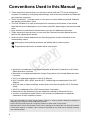
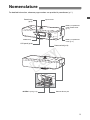
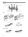
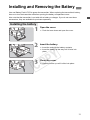
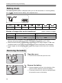
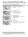
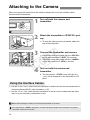
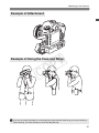
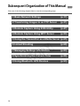
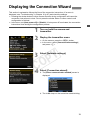

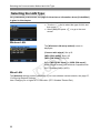
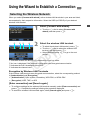

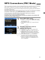

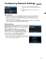

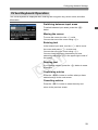

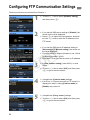
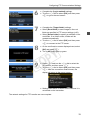
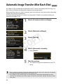

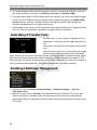
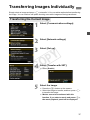
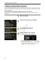
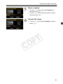
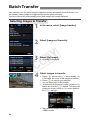

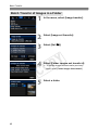
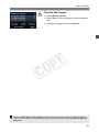

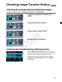


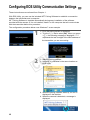
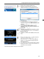
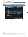

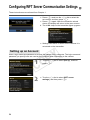
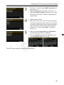
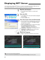
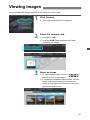
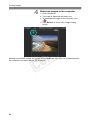

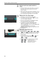
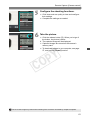
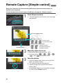
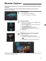
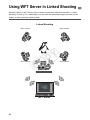
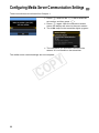
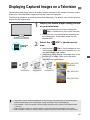

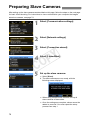
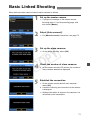
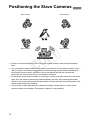
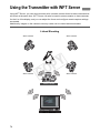
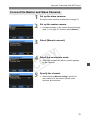
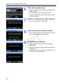
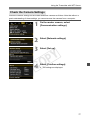
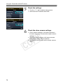
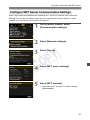
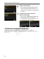
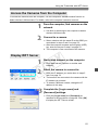
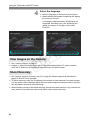
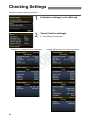
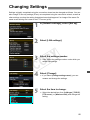

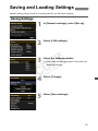
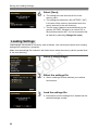

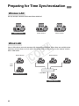
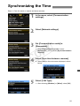
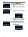
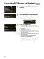
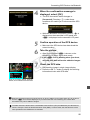
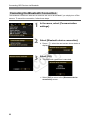

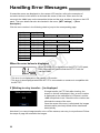
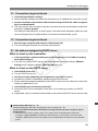


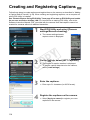
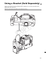
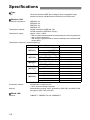
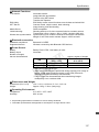


![3 Sélectionnez [Réglages].](http://vs1.manualzilla.com/store/data/006502646_1-716314e518c265d6faa81347dd31fca9-150x150.png)