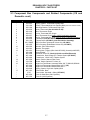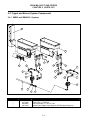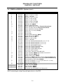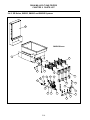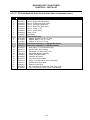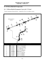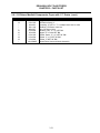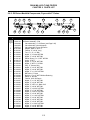
1
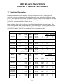
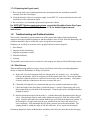
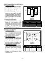
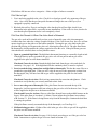
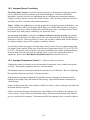
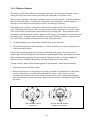
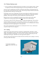
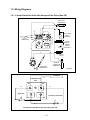
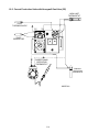
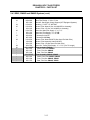
Dean Millivolt Gas Fryers
Service & Parts Manual
Super Runner and Super Marathon Series
NON-CE &
Dean, a member of the Commercial Food Equipment Service Association, recommends using
CFESA Certified Technicians.
www.frymaster.com
24-Hour Service Hotline
1-800-551-8633
Email: [email protected]
NOVEMBER 2005
*8195948*
Please read all sections of this manual and retain for future reference.
NOTICE
This appliance is intended for professional use only and is to be operated by qualified
personnel only. A Dean Factory Authorized Service Center (FASC) or other qualified
professional should perform installation, maintenance, and repairs. Installation, maintenance,
or repairs by unqualified personnel may void the manufacturer’s warranty.
NOTICE
This equipment must be installed in accordance with the appropriate national and local codes of
the country and/or region in which the appliance is installed.
NOTICE
Drawings and photos used in this manual are intended to illustrate operational, cleaning and
technical procedures and may not conform to onsite management operational procedures.
NOTICE
IF, DURING THE WARRANTY PERIOD, THE CUSTOMER USES A PART FOR THIS ENODIS
EQUIPMENT OTHER THAN AN UNMODIFIED NEW OR RECYCLED PART PURCHASED
DIRECTLY FROM FRYMASTER DEAN, OR ANY OF ITS AUTHORIZED SERVICE CENTERS,
AND/OR THE PART BEING USED IS MODIFIED FROM ITS ORIGINAL CONFIGURATION, THIS
WARRANTY WILL BE VOID. FURTHER, FRYMASTER DEAN AND ITS AFFILIATES WILL NOT BE
LIABLE FOR ANY CLAIMS, DAMAGES OR EXPENSES INCURRED BY THE CUSTOMER WHICH
ARISE DIRECTLY OR INDIRECTLY, IN WHOLE OR IN PART, DUE TO THE INSTALLATION OF
ANY MODIFIED PART AND/OR PART RECEIVED FROM AN UNAUTHORIZED SERVICE CENTER.
DANGER
Improper installation, adjustment, maintenance or service, and unauthorized alterations or
modifications can cause property damage, injury, or death. Read the installation, operating and
service instructions thoroughly before installing or servicing this equipment. Only qualified
service personnel may convert this appliance to use a gas other than that for which it was
originally configured.
DANGER
Adequate means must be provided to limit the movement of this appliance without depending
upon the gas line connection. Single fryers equipped with legs must be stabilized by installing
anchor straps. All fryers equipped with casters must be stabilized by installing restraining
chains. If a flexible gas line is used, an additional restraining cable must be connected at all
times when the fryer is in use.
ii
DANGER
The front ledge of the fryer is not a step. Do not stand on the fryer. Serious injury can result
from slips or contact with the hot oil.
DANGER
Do not store or use gasoline or other flammable vapors and liquids in the vicinity of this or any
other cooking appliance.
DANGER
Instructions explaining procedures to be followed MUST be posted in a prominent location in
the event the operator detects a gas leak. This information can be obtained from the local gas
company or gas supplier.
DANGER
The crumb tray in fryers equipped with a filter system must be emptied into a fireproof container
at the end of frying operations each day. Some food particles can spontaneously combust if left
soaking in certain shortening material. Additional information can be obtained in the filtration
manual included with the system.
WARNING
No structural material on the fryer should be altered or removed to accommodate placement of
the fryer under a hood. Questions? Call the Dean Service Hotline at 1-800-551-8633.
WARNING
Do not bang fry baskets or other utensils on the fryer’s joiner strip. The strip is present to seal
the joint between the frypot. Banging fry baskets on the strip to dislodge shortening will distort
the strip, adversely affecting its fit. It is designed for a tight fit and should only be removed for
cleaning.
IMPORTANT
Safe and satisfactory operation of Dean equipment depends upon its proper installation.
Installation MUST conform with local codes, or in the absence of local codes, to European
Community (CE) Standards.
iii
Dean Millivolt Gas Fryers
Service and Parts Manual
TABLE OF CONTENTS
Page #
1.
SERVICE PROCEDURES
1-1
1.1
Functional Description
1-1
1.2
Accessing Fryers for Servicing
1-3
1.3
Cleaning the Gas Valve Vent Tube
1-3
1.4
Calibrating the Operating Thermostat
1-4
1.5
Check Burner Manifold Pressure
1-5
1.6
Adjusting the Pilot Flame
1-6
1.7
Replacing Fryer Components
1-6
1.7.1 Replacing the Operating Thermostat
1-6
1.7.2 Replacing the High-Limit Thermostat
1-8
1.7.3 Replacing the Gas Valve
1-8
1.7.4 Replacing the Frypot
1-8
1.8
1-9
Troubleshooting and Problem Isolation
1.8.1 Pilot Failures
1-9
1.8.2 Improper Burner Functioning
1-12
1.8.3 Improper Temperature Control
1-12
1.8.4 Filtration Problems
1-13
1.8.5 Leaking
1-14
1.9
1-15
Wiring Diagrams
1.9.1 Current Production Units with Honeywell Gas Valve (Non-CE)
1-15
1.9.2 Current Production Units with Honeywell Gas Valve (CE)
1-16
1.9.3 Current Production Units with Robertshaw Gas Valve (After May, 2002)
1-17
1.9.4 UFF Filtration Wiring Diagram
1-18
iv
Dean Millivolt Gas Fryers
Service and Parts Manual
TABLE OF CONTENTS (CONT.)
Page #
2.
PARTS LIST
2-1
2.1
Cabinetry Components, Single Fryers
2-1
2.2
Cabinetry Components, Multi-Battery Systems
2-4
2.3
Component Box Components and Related Components (Non-CE and CE) 2-6
2.4
Frypot and Burner System Components
2-8
2.4.1 SM220 and SM20/20/~ Systems
2-8
2.4.2 SR Series, SM35G, SM40G and SM50G Systems
2-10
2.4.3 SM60G and SM80G Systems
2-13
2.5
Oil Drain Manifold, Drain Flush and Drain Valve Components
2-16
2.6
Oil Return Manifold Components
2-20
2.7
Oil Return and Oil Flush Components
2-23
2.8
Under Fryer Filter (UFF) Components
2-27
2.8.1 SM50 and SM60 Series Fryers (Except IHOP)
2-27
2.8.2 SM50 Series Fryers, IHOP UFF 50 with Filter Leaf
2-28
2.8.3 SM80 Series Fryers
2-29
2.9
2-30
Single Under Fryer Filter (SUFF) Components
2.9.1 SM50 Series Fryers
2-30
2.9.2 SM60 and SM80 Series Fryers
2-31
v
DEAN MILLIVOLT GAS FRYERS
CHAPTER 1: SERVICE PROCEDURES
1.1 Functional Description
Dean Super Runner and Super Marathon Series fryers are millivolt fryers, which require no
electricity to operate (systems with built-in filtration and/or other accessories will require electric
power). Dean millivolt fryers contain a welded steel frypot (stainless or cold-rolled) that is heated
by gas flames diffused evenly through tubes built into the frypot. The number of tubes varies from
three to five, according to the fryer model and size.
Flames originate from orifices in a burner manifold positioned beneath cast-iron burners. The
burners are positioned in the tube openings, at the front of the frypot. Diffusers within each tube
distribute the flame evenly throughout the tube. The diameter of the orifices differs for natural
(CE:G20/G25) and LP (CE:G31) gas as indicated in the accompanying table.
NON-CE (Altitudes of 2000 feet or less)
EQUIPMENT
PRESSURE
MBAR
INCH W.C.
MODEL
INPUT
(BTU)
GAS
TYPE
ORIFICE
MM
(INCH)
ORIFICE
PART NO.
QTY
SM20GM
50
NAT
LP
2.18(#44)
1.40(#54)
810-2050
810-2324
2
2
10
27.5
4
11
SM 35 (40) GM
SR 42GM
105
NAT
LP
2.80(#35)
1.70(#51)
810-2140
810-2064
3
3
10
27.5
4
11
SR 52 GM
SM 50 GM
120
NAT
LP
2.53(#39)
1.51(#53)
810-2048
810-2059
4
4
10
27.5
4
11
SR 62 GM
SM 60 GM
150
NAT
LP
2.53(#39)
1.51(#53)
810-2048
810-2059
5
5
10
27.5
4
11
SM 80 GM
165
NAT
LP
2.58(#38)
1.61(#52)
810-2062
810-2063
5
5
10
27.5
4
11
CE ONLY (Altitudes of 2000 feet or less)
EQUIPMENT
PRESSURE
MBAR
INCH W.C.
MODEL
INPUT
(kW)
GAS
TYPE
ORIFICE
MM
(INCH)
ORIFICE
PART NO.
QTY/
COLOR
SM20GM
15
G20
G25
G31
2,40
2,40
1,51
810-2060
810-2060
810-2059
2/BLUE
2/BLUE
2/RED
10,0
15,0
27,0
4,0
6,0
10,8
SM 35 (40) GM
SR 42GM
26
G20
G25
G31
2,40
2,40
1,51
810-2060
810-2060
810-2059
3/BLUE
3/BLUE
3/RED
10,0
15,0
27,0
4,0
6,0
10,8
SR 52 GM
SM 50 GM
30
G20
G25
G31
2,40
2,40
1,51
810-2060
810-2060
810-2059
4/BLUE
4/BLUE
4/RED
10,0
15,0
27,0
4,0
6,0
10,8
SR 62 GM
SM 60 GM
37,5
G20
G25
G31
2,40
2,40
1,51
810-2060
810-2060
810-2059
5/BLUE
5/BLUE
5/RED
10,0
15,0
27,0
4,0
6,0
10,8
SM 80 GM
37,5
G20
G25
G31
2,40
2,40
1,51
810-2060
810-2060
810-2059
5/BLUE
5/BLUE
5/RED
10,0
15,0
27,0
4,0
6,0
10,8
1-1
1.1 Functional Description (cont.)
An electromechanical millivolt gas valve regulates gas flow to the burner manifold. Dean millivolt
fryers use a pilot ignition system to control burner firing.
High-Limit
Thermopile
Operating
Thermostat
Gas Valve
Pilot
Pilot Magnet
Main Valve Magnet
Functional diagram of a typical millivolt system.
Pilot Ignition System
The pilot ignition system is made up of the pilot orifice, pilot hood, and a thermopile or
thermocouple. The pilot serves two purposes: lighting the burner and heating the thermopile/
thermocouple. In operation, the thermopile/thermocouple is in contact with the pilot flame and
generates millivolts. The millivolt output passes through a normally closed high-limit switch and
energizes the gas valve pilot coil, which in turn opens the pilot valve. If the pilot flame is
extinguished, voltage is lost to the gas valve pilot coil and the pilot valve closes.
Thermostats
Dean millivolt fryers are equipped with adjustable operating thermostats. The temperature at which
the thermostat opens and closes is adjusted by turning a knob.
Dean millivolt fryers are also equipped with a high-limit thermostat. In the event that the fryer fails
to properly control the oil temperature, the high-limit thermostat prevents the fryer from overheating
to the flash point. The high-limit thermostat acts as a normally closed power switch that opens when
exposed to temperatures above 410ºF (210°C) for CE fryers and 435-450ºF (224-232°C) for non-CE
fryers. Once opened, the high limit must be manually reset before operating the fryer.
1-2
1.2 Accessing Fryers for Servicing
DANGER
Moving a fryer filled with cooking oil may cause spilling or splattering of the hot
liquid.
1. Drain all cooking oil from the fryer.
2. Shut off the gas supply to the unit and disconnect the unit from the gas supply.
3. Remove any attached restraining devices.
DANGER
Fryers must be at room temperature, empty of oil, and if fitted with legs, lifted during
movement to avoid damage and possible bodily injury.
DANGER
Hot shortening can cause severe burns. Avoid contact. Under all circumstances, oil
must be removed from the fryer before attempting to move it to avoid oil spills, and
the falls and severe burns that could occur. This fryer may tip and cause personal
injury if not secured in a stationary position.
4. Relocate the fryer for service accessibility. If fryer is equipped with legs, lift the fryer to relocate
it. Damage to the leg or leg support channel can result if the fryer is not lifted when moving.
5. After servicing is complete, reconnect the unit to the gas supply and reattach the restraining
devices.
6. Refill the frypot with cooking oil.
1.3 Cleaning the Gas Valve Vent Tube
1. Set the fryer power switch and the gas valve to the "OFF" position.
2. Carefully unscrew the vent tube from the gas valve. NOTE: The vent tube may be straightened
for ease in removal.
3. Pass a piece of ordinary binding wire through the tube to remove any obstruction. Remove the
wire and blow through the tube to ensure it is clear.
4. Reinstall tube and bend so that the opening is pointing downward.
1-3
1.4 Calibrating the Operating Thermostat
1. Ensure the frypot is filled to the proper level with oil before proceeding.
2. Light the pilot.
3. Set the temperature control knob to 350°F (177°C).
4. Let the burners cycle on and off automatically three times in order for the oil temperature to
become uniform. If using solid shortening, stir to get all shortening in the bottom of the frypot
melted.
5. Insert a good-grade thermometer or pyrometer probe into the oil, with the end near the fryer
temperature-sensing bulb.
NOTE: The temperature-sensing probe is mounted on the frypot tube.
6. When the burner starts for the fourth time, the thermometer/pyrometer reading should be within
the range 335-360°F (168-182°C). If not, calibrate as follows:
a.
Remove the thermostat knob by pulling straight out on the knob with a firm, steady pull.
The temperature adjusting screw is located in the middle of the thermostat shaft.
b.
Insert a small-bladed flat-tipped screwdriver into the adjusting screw. Turn the adjusting
screw in ¼-turn increments to adjust the temperature. Turning the screw clockwise
decreases the temperature; turning it counter-clockwise increases the temperature. DO NOT
allow the thermostat shaft to turn while turning the adjusting screw.
c.
Recheck the thermometer/pyrometer reading the next time the burner comes on.
d.
Repeat steps 4.b through 4.c until the thermometer/pyrometer reading remains within the
range 335-360°F (168-182°C) through several cycles. If the thermostat cannot be calibrated,
call a Factory Authorized Service Center for service.
e.
Reinstall the thermostat knob.
1-4
1.5 Check Burner Manifold Pressure
WARNING
This task should be performed by qualified service personnel only.
1. Ensure that the gas valve knob is in the "OFF" position (non-CE), or press red button to turn gas
valve off (CE).
2. Remove the pressure tap plug from the gas valve (see illustration below).
Pressure tap locations on CE gas valves (left) and non-CE gas valves (right).
3. Insert the fitting for a gas pressure-measuring device into the pressure tap hole.
4. Place the gas valve in the "Pilot" position (non-CE), or press white button and light pilot (CE).
After the pilot is lit (turn non-CE gas valve to "ON" position), set thermostat knob to 350°F
(177°C). When the burner lights and continues to burn, note gas pressure reading for correct
pressure in accordance with the table on page 1-1.
5. To adjust burner gas pressure, remove the cap from the gas valve regulator and adjust to correct
pressure.
6. Place the fryer power switch and the gas valve in the "OFF" position. Remove the pressuremeasuring device fitting from the pressure tap hole and reinstall the pressure tap plug.
7. Repeat step 4 to continue fryer operation.
1-5
1.6 Adjusting the Pilot Flame
1. Remove the cover shown in the illustration below to access the pilot flame adjustment screw in
the gas valve.
Pilot adjustment locations on CE gas valves (left) and non-CE gas valves (right).
2. Using a small, flat-tipped screwdriver, turn the pilot flame adjustment screw counterclockwise to
increase the length of the flame or clockwise to decrease the length of the flame. Adjust the
flame to a length of 1-½ inches (38 mm).
3. Reinstall the pilot flame-adjustment cover.
4. Five-tube millivolt fryers: Adjust the trailing pilot (adjustment valve located on the burner
manifold) until a 1-½ inch (38 mm) flame is obtained.
1.7 Replacing Fryer Components
1.7.1 Replacing the Operating Thermostat
1. Drain the fryer and turn the gas off.
2. Remove the thermostat knob by pulling straight out on the knob with a firm, steady pull.
3. Disconnect the wires from the thermostat.
4. Remove the two mounting screws to release the thermostat control from its mounting bracket.
5. Remove the screws and clamp that secure the thermostat bulb to the frypot. Remove spring from
bulb and reinstall on replacement thermostat bulb.
1-6
1.7.1 Replacing the Operating Thermostat (cont.)
6. First, loosen the capillary tube compression fitting until it slides freely on the capillary tube.
Second, loosen the frypot pass-through nut until it slides freely on the capillary tube. Remove
the capillary tube and bulb from the frypot.
7. Install the replacement thermostat capillary tube and bulb in the frypot. Apply a small amount of
Loctite PST567 compound or equivalent to the threads of the frypot pass-through nut and screw
the replacement thermostat securely into the frypot, being careful not to twist the capillary tube
as the fitting is tightened. DO NOT tighten the capillary tube compression nut at this time.
8. Position the thermostat bulb in tube-mounted clamp and replace mounting hardware. Ensure
probe bulb is properly positioned in the clamp (¼" from burner tube) and screws are properly
tightened.
9. Tighten the capillary tube compression nut once the capillary tube is properly positioned.
NOTE: Once the compression nut is tightened, the capillary tube cannot be repositioned. If a
mistake in installation has been made, a new thermostat will have to be installed.
10. Mount the thermostat control to the mounting bracket using the screws removed in Step 4.
11. Connect the wires disconnected in Step 3 to the thermostat.
Compression Fitting
Thermostat Bulb
Capillary Tube
Frypot Fitting
Operating
Thermostat
12. Install the thermostat knob on thermostat control shaft. Check thermostat calibration and
calibrate if the range is outside of the recommended ranges in section 1.4.
1-7
1.7.2 Replacing the High-Limit Thermostat
1. Follow instructions for replacing operating thermostat, section 1.7.1, omitting steps 2 and 12.
1.7.3 Replacing the Gas Valve
DANGER
Drain the frypot or remove the handle from the drain valve before proceeding further.
1. Disconnect fryer from the gas supply.
2. Disconnect wiring from the gas valve terminal block, marking each wire to facilitate
reconnection.
3. Disconnect the pilot gas line fitting from the gas valve and remove the vent tube.
4. Disconnect the union that connects burner manifold and gas valve piping.
5. Remove all pipefittings from old gas valve and install on new gas valve. Apply a small amount
of Loctite PST567 compound or equivalent to pipe threads prior to installing on new valve. Do
not apply compound to the first two pipe threads. Doing so will clog and damage the gas valve.
6. Reinstall new gas valve following steps 1-4 in reverse.
1.7.4 Replacing the Frypot
1. Drain the frypot and disconnect the fryer from the gas supply.
2. Remove all accessories (e.g., frypot covers, drop-in probes, basket hangers, etc.).
3. Remove the screws from the cabinet back and remove it from the fryer.
4. Remove the screws attaching the flue cap to the frypot and lift the flue cap off the fryer.
5. Remove the door by lifting it upward to disengage the lower hinge pin from the hinge bracket.
Retain any spacers between lower hinge and door for reassembly.
6. Remove the screws from the front cowling and remove the cowling by lifting up and out off the
front lip of the frypot.
7. Remove the screws securing the flue to the frypot and remove it from the fryer.
8. Lift the frypot out of the cabinet, using care not to bump or damage the gas valve/burner
assembly or the thermostat/high-limit. Set the frypot upside down on a clean surface for removal
of the remaining components.
1-8
1.7.4 Replacing the Frypot (cont.)
9. Recover the drain valve, high-limit thermostat, operating thermostat, and burner manifold
assembly from the failed frypot.
10. Clean the threads on the recovered parts, apply Loctite PST 567 or equivalent thread sealer, and
install them on the replacement frypot.
11. Reverse Steps 1-9 to install the replacement frypot in the cabinet.
For SUFF/UFF Filtration-equipped systems, consult the Decathlon Series Gas Fryers
Service & Parts Manual (819-5922), Section 1.7.8, for detailed frypot-removal
instructions.
1.8
Troubleshooting and Problem Isolation
This section is intended to provide technicians with a general knowledge of the broad problem
categories associated with this equipment, and the probable causes of each. With this knowledge, the
technician should be able to isolate and correct any problem encountered.
Problems you are likely to encounter can be grouped into these broad categories:
1. Pilot failures
2. Improper burner functioning
3. Improper temperature control
4. Filtration Problems
5. Leaking
The probable causes and corrective actions for each category are discussed in the following sections.
1.8.1 Pilot Failures
When troubleshooting millivolt systems, always check these areas before performing diagnostic
checks on either the Robertshaw or Honeywell systems:
A. Inspect all wires and component leads for damage (heat, oil, moisture, etc.). On capillary
tube-type thermostats, check for resistance on the thermostat lead wires. Wire nuts and other
connectors cannot be present in a millivolt circuit as they can cause resistance. If resistance
is found, solder the connectors to the wires or replace the wires.
B. Clean and verify that all wire connections and gas valve terminal connections are tight.
C. Check the length of the pilot flame (it should be about 1½-inches (38mm) long) and verify
that it contacts the top one third of the thermopile. Clean the pilot orifice and adjust the pilot
strength if needed.
D. Measure thermopile output with no load (i.e., with the thermopile disconnected from the gas
valve). Measurement must be made with a multimeter having a 0-1000 DC millivolt (MV)
range. Light the pilot and have someone hold the gas cock knob in the depressed position. If
the thermopile is a single lead (coaxial) type, measure from the lead’s end contact to its
screw-in threads. If the thermopile has two leads, measure across the end terminals. The
reading should be within the range of 500-800 millivolts. If not, replace the thermopile.
Performing diagnostic checks on Robertshaw and Honeywell valves are described on the next page.
1-9
ROBERTSHAW-UNITROL 7000 SYSTEM CHECK
1. Complete System Check
With thermostat contacts closed and gas cock
dial in the “ON” position, the main burner
should ignite. Measure the reading between
the 2 & 3 terminals. If the reading is more
than 100MV, replace the gas valve.
TH
TP
THTP
TH
1
2. System Resistance Check
With thermostat contacts closed and main
burner “ON”, measure the millivolt reading
between the 1 and 3 terminals. The reading
should be less than 80MV. If not, recheck the
thermostat leads and connections. Replace
with new or heavier gauge wires if necessary.
If the reading is still greater than 80MV,
replace the thermostat.
3
TH
2
TP
TP
Millivolt Operator
Terminal Panel
3. Automatic Pilot Dropout Check
With the thermostat contacts open, hold the
gas cock knob depressed with the pilot lit until
the maximum millivolt output is observed
between the 1 and 2 terminals.
Then
extinguish the pilot and observe the meter.
The sound of the pilot magnet dropping should
be audible.
This dropout should occur
between 120MV and 30MV. If it occurs
outside these limits, change the gas valve.
(Robertshaw)
Test
1
2
3
Meter
Setting
MV
MV
MV
Meter Leads
On Terminals
2
&
3
1
&
3
1
&
2
Acceptable
Results
<100MV
<80MV
30-120MV
HONEYWELL SYSTEM CHECK
1. Complete System Check
With thermostat contacts closed and gas cock
dial in the “ON” position, main burner should
ignite. If not, measure across terminals 2 and
3 as indicated in the diagram. If the reading is
more than 180MV, replace the gas valve.
4
2. System Resistance Check
With thermostat contacts closed and main
burner “ON”, measure the millivolt reading
between terminals 1 and 3 as indicated in the
diagram. The reading should be 220MV or
less. If not, recheck thermostat leads and
connections. Replace with new or heavier
gauge wires if necessary. If the reading is still
greater than 220MV, replace the thermostat.
3
1
TH
PP
TH
PP
2
Millivolt Operator
Terminal Panel
(Honeywell)
3. Automatic Pilot Dropout Check
With the thermostat contacts open, hold the
gas cock knob depressed with the pilot lit until
the maximum millivolt output is observed
between terminals 1 and 2. Then extinguish
the pilot and observe the meter. The sound of
the pilot magnet dropping should be audible.
This dropout should occur between 110MV
and 36MV. If it occurs outside these limits,
change the gas valve.
Test
1
2
3
1-10
Meter
Setting
MV
MV
MV
Meter Leads On
Terminals
2
&
3
1
&
3
1
&
2
Acceptable
Results
<180MV
<220MV
36-110MV
Pilot failures fall into one of two categories – failure to light or failure to remain lit.
Pilot Fails to Light
1. Gas is not being supplied to the valve: Check for a closed gas cutoff valve upstream of the gas
valve. Also verify that the gas line quick disconnect fitting at the rear of the fryer (if so
equipped) is properly connected.
2. Blocked pilot orifice: If gas is reaching the valve but the pilot will not light, check for an
obstruction in the pilot orifice, especially in new installations. If the orifice is clear, check to be
sure that the pilot adjustment screw is not completely closed.
Pilot Does Not Remain Lit When Gas Valve Knob is Released
The gas valve used on Dean millivolt fryers has a pair of normally open coils (electromagnetic
switches) that close when low voltage is applied to them. If the coils do not close, the valve will not
open to supply gas to the pilot or to the burner manifold. Turning the gas valve knob to the pilot
position and pressing it in bypasses the pilot coil, allowing the pilot to be lit. The pilot flame heats
the thermopile, which generates the voltage required to close the coils. If the pilot flame goes out
when the knob is released, there are four probable causes:
1. Open or grounded high-limit: The high-limit thermostat functions as a normally closed switch.
If the high-limit is open or grounded, the gas valve coil will not pull in and no gas will be
supplied to the pilot or to the burner manifold.
Check and Corrective Action: Detach the high-limit leads from the gas valve and check for
continuity. See page 1-10. If the high-limit fails the continuity check, it must be replaced.
2. Loose/corroded wiring connections on high-limit or thermopile: This has the same effect as a
grounded or open high-limit. If the gas valve coils do not receive the appropriate voltage from
the thermopile, they will not close and no gas will be supplied to the pilot or to the burner
manifold.
Check and Corrective Action: Check wiring connections for corrosion and tightness. Check
terminals to verify that they are securely attached to their leads.
3. Low or no voltage out of thermopile: If the pilot flame does not surround the tip of the
thermopile, it will not generate sufficient voltage to the gas valve coils for them to close. No gas
will be supplied to the pilot or to the burner manifold.
Checks and Corrective Actions: Observe pilot flame located between the middle burners on the
frypot. If the pilot flame is less than 1-½ inches (38 mm) adjust the pilot flame in accordance
with Section 1.6. If the flame is being blown away from the thermopile, eliminate the draft that
is causing the problem.
If the pilot flame correctly surrounds the tip of the thermopile, see D on Page 1-9.
4. Malfunctioning gas valve: If either of the coils in the gas valve fails, no gas will be supplied to
the pilot or to the burner manifold.
Check and Corrective Action: See page 1-10 for check procedures to see if the gas valve has
failed. Instructions to replace the gas valve are found in section 1.7.3.
1-11
1.8.2 Improper Burner Functioning
Fluctuating flame intensity is normally caused by improper or fluctuating incoming gas pressure,
but may also be the result of variations in the kitchen atmosphere. Variation in the kitchen
atmosphere is usually caused by air conditioning and/or ventilation units starting and stopping.
Changes in airflow patterns can also affect flame intensity. If the incoming gas pressure is correct
and stable, check for variations in the kitchen atmosphere.
Flames "rolling" out of the fryer are usually an indication of negative pressure in the kitchen. Air
is being sucked out of the fryer enclosure and the flames are literally following the air. If negative
pressure is not the cause, check for high burner-manifold gas pressure. An obstructed flue, which
prevents the fryer from properly exhausting, may also be the cause.
An excessively noisy burner, especially with flames visible above the flue opening, may indicate
that the burner gas pressure is too high, the gas valve vent tube is blocked, or the tube diffusers are
damaged or worn out. If the gas pressure is correct, the vent tube is unobstructed, and the diffusers
are in good condition, the gas valve regulator is probably defective.
Occasionally a burner may appear to be operating correctly, but the fryer has a slow recovery rate
(the length of time required for the fryer to increase the oil temperature from 275ºF to 325ºF (135ºC
to 163ºC). The primary causes of this are low burner manifold pressure and/or misaligned burners.
If both of these causes are ruled out, the probable cause is a gas valve regulator that is out of
adjustment. Refer to the Check Burner Manifold Pressure procedure in section 1.5.
1.8.3 Improper Temperature Control (i.e., failure to control at set point)
Temperature control is a function of several interrelated components, each of which must operate
correctly. The principle component, however, is the thermostat.
The thermostat must be checked periodically to ensure that it is in calibration. Refer to Calibrating
the Operating Thermostat in section 1.4 for the procedure.
If the thermostat is properly calibrated, the probable causes are damage to the thermostat bulb,
kinking of the capillary tube, and broken or loose wiring. Inspect the thermostat components for
visible damage.
If there are dents in the bulb, if the capillary is kinked, or if there is obvious damage to the leads, the
thermostat should be replaced.
If there is no obvious damage to the thermostat, turn off the gas valve and allow the cooking oil to
cool to at least 15 degrees below the thermostat setting. Disconnect the thermostat leads from the
gas valve and check for continuity. If the thermostat fails the continuity check, it must be replaced.
1-12
1.8.4 Filtration Problems
The majority of filtration problems arise from operator error. One of the most common errors is
placing the filter paper on the bottom of the filter pan rather than over the filter screen.
Whenever the complaint is "the pump is running, but no oil is being filtered", check the installation
and size of the filter paper. Verify that the O-ring on the slip-connection is in good condition. A
missing or worn O-ring allows the pump to suck air, decreasing its efficiency.
If the pump motor overheats, its thermal overload will trip and the motor will not start until it is
reset. If the pump motor does not start, press the red reset switch located on the rear of the motor.
Also, reset the filter circuit breaker located under the fryer control panel. If the pump then starts,
something caused the motor to overheat. Maybe several frypots were filtered one after the other and
the pump got hot. Letting the motor cool down for at least a half-hour is all that is required in this
case. More often, the pump overheated for one of the following reasons:
•
If solid shortening is used: Shortening solidified in the pan or filter lines.
•
The operator attempted to filter unheated oil. Cold oil is thicker and causes the pump motor to
work harder and overheat.
If the motor runs but the pump does not, there is a blockage in the pump. Incorrectly sized or
installed paper allows food particles and sediment to pass through the filter pan and into the pump.
When sediment enters the pump, the gears bind up causing the motor to overheat, tripping the
thermal overload. Solidified shortening in the pump will produce the same result.
A pump seized by debris or hard shortening must be disassembled, cleaned and reassembled.
1. Disconnect power to the filter system.
2. Remove the front cover of the pump to access the gears inside (see illustration- 8-GPM pump
shown), if the pump is accessible while still inside the cabinet. If the front cover is not
accessible, the pump must be removed from the pump motor (remove input/output plumbing
from the pump prior to removing pump). Remove three setscrews to disengage the pump from
the motor.
Remove bolts to remove
pump cover.
Remove debris or hardened
shortening to free gears.
1-13
1.8.4 Filtration Problems (cont.)
3. Prior to reassembly, the inside housing must be clean and free of any sediment or debris. Failure
to completely clean the inside housing and ring gear will cause gear binding after reassembly.
Incorrectly sized or installed paper will allow food particles and sediment to pass through and clog
the suction tube on the bottom of the filter carriage. Particles large enough to block the suction tube
may indicate that the crumb tray is not being used.
Pan blockage can also occur if shortening is left in the pan and allowed to solidify. Heater strips (if
equipped) on the oil return plumbing are designed to prevent solidification of shortening left in the
plumbing. Heater strips will not melt or prevent solidification of shortening in the pan.
Blockage removal can be accomplished by forcing the item out with an auger or drain snake.
Compressed air or other pressurized gases should not be used to force out the blockage.
The electronics of the SUFF/UFF filtration systems are simple and straightforward. Microswitches,
attached to handles for each vat and wired in parallel, provide the 24 VAC required to activate the
pump relay coil when the handles are moved to the ON position. The activated pump relay coil pulls
in the pump motor switch, supplying power to the pump motor.
Filter systems equipped with oil-return heaters are wired into the 120 VAC source, which remain
energized as long as the unit is plugged in.
1.8.5 Leaking
Leakage of the frypot usually will be due to improperly sealed high-limits, thermostats, or drain
fittings. When installed or replaced, each of these components must be sealed with Loctite PST567
sealant or equivalent to prevent leakage. In very rare cases, a leak may develop along one of the
welded edges of the frypot. When this occurs, the frypot must be replaced.
If the sides and/or ends of the frypot are coated with oil, the most likely cause is spillage over the top
of the frypot rather than leakage.
Frypot locations (indicated by
arrows) where potential leaks could
occur.
1-14
1.9 Wiring Diagrams
1.9.1 Current Production Units with Honeywell Gas Valve (Non-CE)
HIGH-LIMIT
THERMOSTAT
12C
TH
SAFTY DRAIN
SWITCH
(OPTIONAL)
PILOT
ADJ.
PP
1/2 P.S.I.
HONEYWELL
TH
PILOT
ON
OFF
17C
HONEYWELL 1/2 P.S.I.
PP
C
PILOT
GENERATOR
IN-LINE
SPLICE
ON/OFF
SWITCH
(OPTIONAL)
1/2 P.S.I.
HONEYWELL
1C
17C
2C
IN-LINE
SPLICE
FENWALL
OPERATING
THERMOSTAT
OPERATING
THERMOSTAT
8050438D
White
Thermopile
Red
Combination Gas
Valve
TH
PP
Red
Red
High-Limit
Operating Thermostat
PP
TH
Black
Black
Old Style Honeywell Millivolt Gas Valve Wiring (Non-CE)
1-15
1.9.2 Current Production Units with Honeywell Gas Valve (CE)
HIGH-LIMIT
THERMOSTAT
PILOT
THERMOCOUPLE
PP
PILOT
GENERATOR
PP
TH
TH
ROBERTSHAW
OPERATING
THERMOSTAT
FENWALL
OPERATING
THERMOSTAT
8050531A
1-16
High-Limit Thermostat
1.9.3 Current Production Units with Robertshaw Gas Valve (After May, 2002)
1C
2C
TH
TP
TH
TP
Operating Thermostat
Thermopile
1-17
120V W/OUT
XFORMER
P/N 807-3773
GRN
75 VA TRANSFORMER
H1
GRN
BLK
WHT #2
BLK
WHT#1
5 AMP-480V
P/N 807-3538
P1
P2
T3
T5
T2
T4
LOW VOLTAGE SHOWN
T8
BY-PASS SWITCH
YEL
YEL
CIRCUIT BREAKER
7 AMP-120V
P/N 807-3577
BLK #2
CB
240V SEC.
480V PRIM.
WHT #2
H4
8051376A
BLK #2
H2 H3
480VAC
SHOWN
WHT
WHT
BLK
J BOX
BLU
WHT
GRN
PN 807-1420
1 2
YEL
WHT
WHT
WHT
YEL
24V
COM
NO
NC
COM
RED
NC
NO
ADD ON ASSY
FROM LEFT
FRYER(S)
WHEN USED
OIL RETURN
LH FRYER
WHT
1 2
1 2
PUR
ORG
BLK
R1
P/N 807-3611
230V FILTER CIRCUIT
230V FILTER CIRCUIT
36" LONG LEADS
SCF OIL RETURN
TRANSFORMER/RELAY ASSY
BLOCK
P/N 810-1164
HEAT TAPE - 25 WATT
JUCTION BOX P/N 807-3642
COVER PLATE P/N 807-3643
FUSE P/N 807-3592
FUSE HOLDER P/N 807-1321
FUSE
2 AMP
P/N 810-2100
MOTOR
24V
FOR CHANGE OF ROTATION INTERCHANGE
LEADS T5 AND T8 ON MOTOR
P1
T8
T3
P2
T5
T4
T2
HIGH VOLTAGE SHOWN
AMP
CONNECT
WHT#1
1 2
1 2
BLK
ORG
T2
T1
SPST
1 2 3 4
P/N 807-2196
8" LONG LEADS
1-18
COM
RED
RED
NC
NO
MICROSWITCH
SHOWN IN
OFF POSITION
P/N 807-2104
OIL POLISHING
HOSE CONNECTION
WHEN USED
WHT
1 2
1 2
WHT
8" LONG LEADS
WHT#2
ORG
COM
RED
RED
NC
NO
ADD ON ASSY
FROM RH
FRYER(S)
WHEN USED
OIL RETURN
RH FRYER
WHT
1 2
1 2
WHT
8" LONG LEADS
OPTIONAL
POWER
SWITCH
1 2
1.9.4 UFF Filtration Wiring Diagram
DEAN MILLIVOLT GAS FRYERS
CHAPTER 2: PARTS LIST
2.1 Cabinetry Components, Single Fryers
19
20
15
14
17
18
16
24
21
28
2
12
27
1
22
11
9
23
3
7
8
26
25
10
13
5
6
4
ITEM
*
*
*
*
1
*
*
*
*
*
*
2
3
* Not Illustrated
PART #
810-2793
200-1360
210-1595
210-5109
12-0373
200-1118
200-5655
200-3269
200-2493
200-2686
823-3248
806-5043
COMPONENT
Basket Hanger SR142 (Hook Over the Flue) Thumbscrews not needed
Basket Hanger SR42 (Thumbscrew 809-0171, Cage Nut 826-1351)
Basket Hanger SM-50 Single (Use 210-3131 for double)
Joiner Strip SM20, SM50
Channel, Base- Front & Rear (Non-Filtration Single Fryers)
Channel, Base- Front & Rear- SR38G obsolete
Channel, Base- Front & Rear- SR42G, SR52G, SM220G SM35G, SM40G, SM50G
Channel, Base- Front & Rear-SR62G
Channel, Base- Front & Rear- SM20G
Channel, Base- Front & Rear- SM60G
Channel, Base- Front & Rear- SM80G
Support, Leg (Use Where Applicable)
Leg, Adjustable- With Mounting Plate- All Millivolt Fryers
2-1
DEAN MILLIVOLT GAS FRYERS
CHAPTER 2: PARTS LIST
2.1 Cabinetry Components, Single Fryers (cont.)
ITEM
4
5
PART #
810-0357
810-0356
6
823-3791
*
823-3792
*
823-3724
7
202-3529
*
201-3259
*
200-3459
8
210-3636
9
823-3751
*
823-3788
10
823-3752
*
823-3789
11
200-3522
*
200-3494
*
200-3403
12
823-3783
*
823-3765
*
823-3745
13
200-3524
*
200-3461
14
*
12-0380-1
*
201-1137SP
*
211-3329
*
201-2858
*
201-1299
*
211-2076
*
211-2532
15
*
12-0380-2
*
202-1137
*
212-3329
*
202-2858
*
202-1299
*
212-2076
*
212-2532
16
210-2804
*
200-1471
17
12-0311
*
200-1121
*
200-1676
*
200-3558
*
200-2856
*
200-1213
*
200-3004
18
12-0309-2
*
210-1141
*
07-0132
*
824-1033
* Not Illustrated
COMPONENT
Caster, Swivel- With Brake- All Millivolt Fryers
Caster, Swivel- Without Brake- All Millivolt Fryers
SUFF Base Components- SM Series With SUFF Filtration
Support, Leg- Left- SUFF 50- SM40G, SM50G
Support, Leg- Right- SUFF 50- SM40G, SM50G
Support, Leg- Left & Right- SUFF 60/80- SM60G, SM80G
Base, Channel- Right- SUFF 50- SM40G, SM50G
Base, Channel- Left- SUFF 50- SM40G, SM50G
Base, Channel- Right & Left- SUFF 60/80- SM60G, SM80G
Slide, Front- SUFF Filter, All Systems
Slide, Rear, Left- SUFF Filter- SM60G, SM80G
Slide, Rear, Left- SUFF Filter- SM50G
Slide, Rear, Right- SUFF Filter- SM60G, SM80G
Slide, Rear, Right- SUFF Filter- SM50G
Base, Lower Filter- SUFF 50- SM40G, SM50G
Base, Lower Filter- SUFF 60- SM60G
Base, Lower Filter- SUFF 80- SM80G
Base, Upper Filter- SUFF 50- SM40G, SM50G
Base, Upper Filter- SUFF 60- SM60G
Base, Upper Filter- SUFF 80- SM80G
Cover, Electrical Access- SUFF 50- SM40G, SM50G
Cover, Electrical Access- SUFF 60- SM60G, SM80G
Side Panel, Left
Side Panel, Left- Painted Aluminum- SR38G obsolete
Side Panel, Left- Painted Aluminum-SR42G, SR52G (Use 202-5693SP for SR62G)
Side Panel, Left- SM20G
Side Panel, Left- Painted CRS- SM35G, SM50G
Side Panel, Left- Painted CRS- SM50GDD
Side Panel, Left- S/S- SR42G, SM35G, SM50G (Use 211-5693 for SR62G)
Side Panel, Left- S/S- SM60G, SM80G
Side Panel, Right
Side Panel, Right- Painted Aluminum- SR38G obsolete
Side Panel, Right- Painted Aluminum- SR42G, SR52G (Use 202-5693SP for SR62G)
Side Panel, Right- SM20G
Side Panel, Right- Painted CRS- SM35G, SM50G
Side Panel, Right- Painted CRS- SM50GDD
Side Panel, Right- S/S- SR42G, SM35G, SM50G (Use 212-5693 for SR62G)
Side Panel, Right- S/S- SM60G, SM80G
Duct, Door Access- S/S- All Millivolt Fryers
Duct, Door Access- Painted- All Millivolt Fryers
Back, Control Panel- SR38G obsolete
Back, Control Panel- SR42G, SR52G, SM220G (Use 200-3003 for SR62G)
Back, Control Panel- SM35G, SM40G, SM50G
Back, Control Panel- SM50GDD
Back, Control Panel- SM60G
Back, Control Panel- SM60G
Back, Control Panel- SM80G
Top Cap (Front Canopy)- SR38G obsolete
Top Cap (Front Canopy)- SR42G, SR52G, SM35G, SM40G, SM50G
Top Cap (Front Canopy)- SM20G obsolete
Top Cap (Front Canopy)- SM220G
2-2
DEAN MILLIVOLT GAS FRYERS
CHAPTER 2: PARTS LIST
2.1 Cabinetry Components, Single Fryers (cont.)
ITEM
*
*
*
19
*
*
*
*
*
*
*
*
*
20
*
*
*
*
*
21
*
*
*
PART #
210-3419
210-2821
210-2811
12-0366-2
823-4175
823-4437
823-3467
823-3700
823-3702
823-3521
823-3575
823-3635
823-3512
12-0401
200-1123
200-1377
200-1674
200-1213
200-2683
12-0402
200-1126
200-1327
210-2684
22
200-3807
*
200-1379
*
200-1185
*
200-2688
23
12-0308-2
*
210-4770
*
210-5642
*
106-4728
*
210-3805
*
210-2869
*
210-1424
*
210-1151
24
200-1301
*
106-1698SP
25
809-0413
26
200-1307
*
200-1675
27
810-0180
*
809-0918
*
809-0191
*
810-1422
*
826-1379
28
810-0066
*
823-3225
*
200-3663
*
210-2897
*
803-0197
* Not Illustrated
COMPONENT
Top Cap (Front Canopy)- SM50GDD
Top Cap (Front Canopy)- SM60G, SR62G
Top Cap (Front Canopy)- SM80G
Flue Cap- SR38G obsolete
Flue Cap- SR42G, SR52G (After Feb. 2003 ) obsolete Use 230-0031
Flue Cap- SR62G
Flue Cap- SM35G, SM40G (SR42G, SR52G Prior To Feb. 2003) obsolete
Flue Cap- SM20G
Flue Cap- SM220G
Flue Cap- SM50G
Flue Cap- SM50GDD
Flue Cap- SM60G
Flue Cap- SM80G
Back, Upper Cabinet- SR38G obsolete
Back, Upper Cabinet- SR42G, SR52G, SM35G, SM50G
Back, One-Piece Cabinet- SM35G, SM50G
Back, Upper Cabinet- SM50G (SUFF), SM220G
Back, Upper Cabinet- SM60G / SR62G
Back, Upper Cabinet- SM80G
Back, Lower Cabinet- SR38G obsolete
Back, Lower Cabinet- SM35G, SM50G, SM50GDD
Back, Lower Cabinet- SM60G
Back, Lower Cabinet- SM80G
Door Assembly Components
Panel, Inner Door- SM20G
Panel, Inner Door- SM220G, SM35G, SM40G, SM50G
Panel, Inner Door- SM60G
Panel, Inner Door- SM80G
Panel, Door- SR38G obsolete
Panel, Door- SR42G, SR52G (Assembly 106-3150SP)
Panel, Door- SR62G (Assembly 106-3444SP)
Door Assembly, Right with Liner- SM50
Panel, Outer Door- SM20G (Assembly 106-2482SP)
Panel, Outer Door- SM220G, SM35G, SM40G, SM50G (Assembly 106-1754SP)
Panel, Outer Door- SM60G
Panel, Outer Door- SM80G (Assembly 106-1698SP)
Pin, Door- All Millivolt Fryers (Use 826-1343 for Springs qty. 10)
Pin, Door Assembly- All Millivolt Fryers (short)
Spacer, Nylon- All Millivolt Fryers
Hinge, Door- Lower- All SR Series Fryers
Hinge, Door- Lower- All SM Series Fryers
Handle, Door- Chrome- All SM Series Fryers
Screw, #10-24 x ½" (Use With 810-2105)
Washer, Lock ¼" (Use With 810-2105)
Handle, Wireform- Door- SR42G, SR52G (Use 810-2030 before Jan. 03)
Screw, #10 x ½" Round Phillips (Qty: 10) (Use With 810-1422)
Catch, Magnetic Door- All Millivolt Fryers
Splash Guard 42’s & 50’s (Use 823-4767 for 60’s & 80’s)
Striker Plate all models except SR42
Striker Plate SR42
Fryers Friend Cleanout Tool
2-3
DEAN MILLIVOLT GAS FRYERS
CHAPTER 2: PARTS LIST
2.2 Cabinetry Components, Multi-Battery Frying Systems
See Section 2.1 for single
fryer components.
17
5
7
2
4
6
3
16
1
18
15
19
20
8
11
9
ITEM
1
*
*
2
*
*
3
4
5
6
7
8
PART #
211-3261
211-2787
201-3369
212-3261
212-2787
202-3369
210-2804
202-2799
201-2799
202-3268
201-3268
200-1148
*
9
10
11
*
12
13
200-3154
823-3248
823-3539
200-2783
200-1198
200-1675
200-1393
14
* Not Illustrated
200-2308
10
14
12
13
COMPONENT
Side, Left- S/S- (Use When SM20G Is On End)
Side, Left- S/S- (Use When SM50G Is On End)
Side, Left- Painted (Use When SM50G is On End)
Side, Right- S/S- (Use When SM20G Is On End)
Side, Right- S/S- (Use When SM50G Is On End)
Side, Right- Painted (Use When SM50G is On End)
Duct, Door Access- All SM Series Multi-Battery Fryers
Panel, Inner- SUFF Base-Right- SM50G
Panel, Inner- SUFF Base-Left- SM50G
Panel, Inner- Right- SM20G To SM50G
Panel, Inner- Left- SM20G To SM50G
Base Channel, Front & Rear- SM220G, SM50G (See Section 2.1 For
Additional Single Fryer Base Channel Components)
Channel, Double- Front & Rear- SM80G Systems (4-Battery)
Support, Leg- All SM 60/80 Series Multi-Battery Fryers With UFF
Support, Leg- All SM 20/50 & 50 Series Multi-Battery Fryers With UFF
Channel, Filter Base- All SM 20/50 Series UFF-Equipped
Channel, Filter Base- All SM60G-80G Series UFF-Equipped
Bracket, Lower Hinge- All SM Series UFF-Equipped
Channel, Lower Joiner- All SM 20/50 & 50 Series Multi-Battery Fryers
With UFF
Post, Door- All SM 20/50 & 50 Series Multi-Battery Fryers With UFF
2-4
DEAN MILLIVOLT GAS FRYERS
CHAPTER 2: PARTS LIST
2.2 Cabinetry Components, Multi-Battery Frying Systems
ITEM
15
16
17
*
*
*
18
*
*
19
*
20
*
*
*
*
*
*
*
*
*
*
*
*
*
*
*
*
*
PART #
200-2830
200-2785
823-3634
823-3705
823-3516
823-3659
824-0995
824-0993
824-1128
824-1025
824-1026
824-1029
824-1030
824-1028
824-1177
824-0999
824-1000
824-1001
210-2822
210-2824
210-2825
824-1009
824-1010
824-1011
210-5109
210-3182
210-1679
210-2681
KIT00092SP
*
*
*
*
*
*
*
*
*
*
*
*
*
*
*
*
*
*
* Not Illustrated
803-0271
803-0304
803-0277
803-0280
803-0273
803-0327
210-3911
210-3368
210-1595
200-1360
210-2737SP
810-2793
810-2794
106-2631SP
809-0171
106-1637SP
106-1479SP
106-2470
COMPONENT
Base, Filter Frame- Lower- SM 20/50 & 50 Series Multi-Battery Fryers w/ UFF
Base, Filter Frame- Upper- SM 20/50 & 50 Series Multi-Battery Fryers w/ UFF
Fluecap, SM250G
Fluecap, SM20/20/50G
Fluecap, SM260G
Fluecap, SM280G
Wireway, Control Panel- SM50G
Wireway, Control Panel- SM60G
Wireway, Control Panel- SM80G
Wireway, Control Panel- SM220G
Wireway, Control Panel- SM20G
Topcap- SM20/20/50/50G
Topcap- SM20/50/50/20G
Topcap- SM20/20/50G
Topcap- SM20/20/50G 3-Battery
Topcap- SM250G
Topcap- SM350G
Topcap- SM450G
Topcap- SM260G
Topcap- SM360G
Topcap- SM460G
Topcap- SM280G
Topcap- SM380G
Topcap- SM480G
Joiner Strip- SM22G
Joiner Strip- SM50/60, SR62G
Joiner Strip- SM220
Joiner Strip- SR42
Air Shutter Kit
ACCESSORIES
Basket, Fry (SM20, SM40, SM50, SR42 and SR52
Basket, Fry (SM60 and SM80)
Screen, Fine Mesh SR42 (Use 803-0149 for SR62, SM60)
Screen, Fine Mesh SM80
Rack, Basket Support SR42
Grid Assembly SM20 Basket Rack
Hanger, Basket 20/50/MC
Hanger, Basket SM20 (Hooks over the Flue)
Hanger, Basket SM35/40/50 SS 15½”
Hanger, Basket (Over flue style) SR42/52 CR 15½”
Hanger, Basket SR62/SM60/SM160G SS 20” (Hooks over Flue)
Hanger, Wire Basket Single SR42/50
Hanger, Wire Basket Double SR42/50/62
Tray Assembly, Sediment SM60
Thumbscrew (Nut 826-1351 qty. 10)
Frypot Cover SR42/52, SM50
Frypot Cover SM60
Frypot Cover SM80
2-5
DEAN MILLIVOLT GAS FRYERS
CHAPTER 2: PARTS LIST
2.3 Component Box Components and Related Components (CE and
Domestic)*
* Components are applicable to all Millivolt fryers covered in this manual unless otherwise noted.
1
5
3
2
7
4
8
6
9
12
13
16
17
2-6
11
10
14
15
DEAN MILLIVOLT GAS FRYERS
CHAPTER 2: PARTS LIST
2.3 Component Box Components and Related Components (CE and
Domestic- cont.)
ITEM
1
*
*
*
2
3
4
5
6
7
8
9
*
10
11
12
*
*
13
*
14
15
16
*
*
*
17
*
*
*
* Not Illustrated
PART #
826-2013
810-2047
210-1302
200-1320
810-2035
200-1618
200-3217
200-3277
200-3906
810-2033
810-1152
106-1768SP
106-1879
200-5479
810-2401
810-1001
200-1868
807-3540
807-1999
807-0800
807-3580
210-2786
807-3516
807-3560
807-3680
810-2046
807-1321
2747
807-3592
807-3750
COMPONENT
Thermostat, Sunne (Use 807-1692 for CE)
Spring, Spacer- Thermostat Capillary Bulb
Clamp, Thermostat/High Limit Capillary Bulb (Use 210-1433 for 2 hole)
Mounting Bracket, Thermostat & High-Limit
Knob, Thermostat (Use 816-0139 for CE)
Box, Thermostat- Single
Cover, Thermostat Box- Single
Box, Thermostat- Dual (Used in 20/50 Combination Systems)
Cover, Thermostat Box- Dual (Used in 20/50 Combination Systems)
Thermopile (Use 807-3565 for CE)
Thermocouple (CE ONLY) (Use 812-1284 for Assembly)
ECO Connector (Honeywell Valves Only- CE ONLY)
ECO Connector (Robertshaw Valves Only- CE ONLY)
Bracket, Pilot Thermocouple
Bracket, Thermopile
Piezo Ignitor (Trigger) (Wire Lead-807-3650) (Assembly-44970SP)
Piezo Bracket
Electrode, Piezo CE (Use 812-1532 for modified Electrode)
Transformer, Dual Voltage CE- Filtration System (CE ONLY)
Transformer, 120/24 VAC- Filtration System
Switch, Rocker- Manual Filter Power
Guard, Switch (Optional- For Item 10)
High-Limit Thermostat- Automatic Reset 435° F SM20/35,SR40/42
High-Limit Thermostat- Manual Reset 410° F (CE)
High-Limit Thermostat- Manual Reset 450° F
Spring, Spacer- High Limit Capillary Bulb
Fuse Holder, Buss
Fuse Holder, Slot-head—Safety (CE ONLY)
Fuse 2A Slow-Blow (230V Systems)
Fuse 5A (120V Systems)
2-7
DEAN MILLIVOLT GAS FRYERS
CHAPTER 2: PARTS LIST
2.4 Frypot and Burner System Components
2.4.1 SM220 and SM20/20/~ Systems
22
18
20
21
8
19
13
12
16
9
11
7
6
5
10
14
15
17
1
2
3
ITEM
1
*
*
*
* Not Illustrated
PART #
813-0737
810-2043
809-0805
200-1450
4
COMPONENT
Nipple, ½" NPT x 21" BM
Clamp, Pipe- ½" BM Pipe
Bolt, Pipe Clamp- ¼" -20 x ½" Hex
Bracket, Gas-Supply Clamp Support (UFF-Equipped Systems)
2-8
DEAN MILLIVOLT GAS FRYERS
CHAPTER 2: PARTS LIST
2.4.1 SM220 and SM20/20/~ Systems (cont.)
ITEM
2
3
4
5
6
7
8
9
10
*
11
*
*
*
12
13
*
*
14
15
16
17
*
*
*
*
*
*
*
*
18
*
19
20
*
*
21
*
22
*
*
*
*
* Not Illustrated
PART #
813-0003
813-0087
813-0173
813-0780
813-0631
813-0676
813-0625
813-0649
810-2352
200-1615
810-2050
810-0710
810-2060
810-2059
810-2151
810-2150
200-1374
200-1331
813-0668
813-0782
813-0781
807-3645
807-1603
810-2036
807-2122
810-2399
807-1604
807-2121
810-0975
810-0691
826-1874
826-1875
200-5175
810-2158
810-2689
106-4968
810-0703
810-2602
106-1583SP
200-1342
200-1344
200-1351
200-3081
COMPONENT
Tee, ½" NPT BM
Nipple, ½" NPT x 1-½" BM
Union, ½" NPT BM
Bushing, ⅜" NPT x ½" BM
Elbow, ⅜" NPT 90° BM
Nipple, ⅜" NPT x 2" BM
Nipple, ⅜" NPT x Close BM
Nipple, ⅜" NPT x 2-½" BM
Manifold, Gas- SM20G
Bracket, Manifold Mounting
Orifice, Natural- #44 (2.18 mm)- Domestic/International
Orifice, LP- #54 (1.40 mm)- Domestic/International
Orifice, G20-G25- (2.40 mm)- CE Only
Orifice, G31- (1.51 mm)- CE Only
Burner, Left
Burner, Right
Bracket, Burner Mounting- SM20G
Shield, Burner Heat- SM20G
Nipple, ⅜" NPT x 7" BM
Nipple, ⅜" NPT x 5" BM
Union, ⅜" NPT BM
Valve, Gas- Natural (Robertshaw MV) ½” in x ¾” out
Valve, Gas- Natural Honeywell ½” in x ½” out
Valve, Gas- Natural Honeywell ½” in x ¾” out
Valve, Gas- Natural CE Honeywell
Valve, Gas- Propane (Robertshaw MV)
Valve, Gas- Propane Honeywell
Valve, Gas- Propane CE Honeywell
Knob, Gas Valve Honeywell
Vent Tube 4” (Use 810-1166 for CE 3.86”)
Frypot Assembly- SM20G- M/S obsolete use 826-1875
Frypot Assembly- SM20G- S/S
Diffuser, Burner-Tube- SM20G
Pilot Burner- SM20G- Natural(0.18 Orifice) (Use 810-2526 for LP)
Pilot Assembly Honeywell w/ Piezo- Natural (Use 810-2690 for LP)
Pilot Assembly w/ Piezo-Natural SM20G
Gas Line, Pilot Supply- ¼” x 17-½" (CE -810-1172 - ¼” x 22”)
Gas Line, Pilot Supply- ¼” x 25"
Flue Assembly- SM20G
Shield, Flue Heat- SM20G
Front, Flue Box- SM20G
Rear, Flue Box- SM20G
Air Shutter (Use KIT00092SP for Air Shutter Kit)
SM 20 series began using Honeywell gas valves in July 2003.
2-9
DEAN MILLIVOLT GAS FRYERS
CHAPTER 2: PARTS LIST
2.4.2 SR Series, SM35G, SM40G and SM50G Systems
25
SM50G Shown
1
2
24
22
23
5
17
19
16
3
15
20
21
6
4
8
18
7
14
13
12
9
10
11
2-10
DEAN MILLIVOLT GAS FRYERS
CHAPTER 2: PARTS LIST
2.4.2 SR Series, SM35G, SM40G and SM50G Systems (cont.)
ITEM
1
*
*
*
*
*
*
*
2
*
*
3
*
4
*
5
*
*
*
*
PART #
12188-1
12188-2
12082NV
12202-1
12202-2
826-1865
826-1871
826-1867
210-5185
210-5175
210-5216
810-2150
810-2039
810-2149
810-2038
810-2151
810-2037
200-1329
809-0459
823-3600
*
*
6
*
7
8
9
10
*
*
*
*
*
*
*
*
*
*
*
11
*
*
* Not Illustrated
200-1129
200-1330
200-1615
200-1311
809-0428
809-0823
813-0705
810-2048
810-2132
810-2040
810-2497
810-2059
810-2063
810-2064
810-2400
810-2060
810-2059
823-3618
810-2034
823-3619
COMPONENT
Frypot- M/S (After 6/98)- SR38G obsolete
Frypot- S/S (After 6/98)- SR38G obsolete
Frypot- M/S (P&S Prior to 6/98)- SR38G obsolete
Frypot- M/S (Japan/Singapore)- SR38G obsolete
Frypot- S/S (Japan/Singapore)- SR38G obsolete
Frypot- S/S- SR42G (Began using 1” drain Mar. 2003)
Frypot- S/S- SR52G, SM50G
Frypot- S/S- SM35G, SM40G
Diffuser, Burner Tube- SR38G, SR42G, SM35G, SM40G
Diffuser, Burner Tube- SM50G
Diffuser, Burner Tube- SR52G
Burner, Right- SR52G, SM50G
Burner, Right- SR38G, SR42G, SM35G, SM40G
Burner, Center- SR52G, SM50G
Burner, Center- SR38G, SR42G, SM35G, SM40G
Burner, Left- SR52G, SM50G
Burner, Left- SR38G, SR42G, SM35G, SM40G
Bracket, Burner Mounting- SR52G, SM50G
Bolts, Burner 5/16" – 18x ¾" Hex Head Washer
Support Assembly, Burner- SM35G, SM40G (Includes Burner
Mounting Bracket & Heat Shield)
Shield, Burner Heat- SR42G not used after 12/10/04
Shield, Burner Heat- SR52G, SM50 and 200-1331
Bracket, Manifold Mounting- SR52G, SM50G
Bracket, Manifold Mounting- SR38G, SR42G
Bolt, ¼" -20 x ½" Hex Head
Nut, Nylock- ¼" -20
Plug, Brass- ⅛" Square Head
Orifice- Domestic/International
Orifice, Natural- #39 (2.53 mm)- SR52G, SM50G,
Orifice, Natural- #37 (2.64 mm)- SR38G
Orifice, Natural- #35 (2.80 mm)- SR42G, SM35G, SM40G
Orifice, LP- #55 (1.32 mm)- SR52G, SR62G, SM20G, SM50G
Orifice, LP- #53 (1.51 mm)- SR52G, SM50G,
Orifice, LP- #52 (1.61 mm)- SR38G
Orifice, LP- #51 (1.70 mm)- SR42G, SM35G, SM40G
Orifice, LP- #16 (.016)- Pilot SR52
Orifice- CE Only
Orifice, G20-G25- (2.40 mm)- All Millivolt Fryers in This Section
Orifice, G31- (1.51 mm)- All Millivolt Fryers in This Section
Manifold, Gas- SR52G, SM50G
Manifold, Gas- SR38G, SR42G
Manifold, Gas- SM35G, SM40G
2-11
DEAN MILLIVOLT GAS FRYERS
CHAPTER 2: PARTS LIST
2.4.2 SR Series, SM35G, SM40G and SM50G Systems (cont.)
ITEM
PART #
COMPONENT
Gas Valve and Related Plumbing- SM50G – Plumbing Will Vary From Model to
Model- Use the Following Parts As A Reference When Obtaining Parts For Systems
in This Section Other Than SM50G
12
813-0165
13
810-2036
*
807-1603
*
807-3648
*
807-3645
*
807-3549
*
807-1604
*
807-3553
*
810-1155
*
807-2122
*
807-2121
*
807-1846
14
813-0418
*
813-0670
*
813-0585
*
813-0737
15
813-0174
16
813-0254
17
813-0066
18
813-0112
19
809-0805
20
810-2043
*
200-1450
21
813-0031
22
810-0703
23
810-2033
*
807-3565
24
810-2032
*
810-2155
25
106-1742SP
*
200-2872
*
200-1343
*
200-1350
*
12203
*
12-0363
*
12-0362
*
12-0361
*
106-0696SP
*
200-1304
*
200-1303
*
106-0954SP
*
200-1690
*
200-1701
*
200-1678
*
449-41001
*
449-4100001
* Not Illustrated
Elbow, Street- ½" NPT 90° BM
Valve, Gas- Natural, Honeywell- Domestic/International ½” in x ¾” out
Valve, Gas- Natural, Honeywell- ½” in x ½” out Started using Feb. 2003
Valve, Gas- Natural, Honeywell- ¾” in x ¾” out Started using Feb. 2003 Export
Valve, Gas- Natural, Robertshaw- ½” in x ¾” out
Valve, Gas- LP, Honeywell- Domestic/International
Valve, Gas- LP, Honeywell- ½” in x ½” out Started using Feb. 2003
Valve, Gas- LP, Honeywell- ¾” in x ¾” out
CE Adaptor Kit, Honeywell Valve
Valve, Gas- Natural, Honeywell- CE Only
Valve, Gas- LP, Honeywell- CE Only
Valve, Kit – Natural to Propane Conversion
Nipple, ½” NPT x 17" BM- SM50G
Nipple, ½” NPT x 19" BM (Measure To Confirm Length)
Nipple, ½” NPT x 20-½" BM (Measure To Confirm Length)
Nipple, ½” NPT x 21" BM (Measure To Confirm Length)
Union- ¾" NPT BM
Nipple, ¾” NPT x 3" BM- SM50G
Elbow- ¾” NPT 90° BM
Nipple, ¾” NPT x 2" BM- SM50G
Bolt, ¼”-20 x ½" Hex Head
Clamp, Pipe- ½"
Bracket, Gas-Supply Clamp Support (UFF-Equipped Systems)
Bushing, ¾” NPT x ½” NPT BM
Gas Line, Pilot Supply- ¼” x 17-½" (For CE use 810-1172 23” or 810-2602 25”)
Thermopile- Non-CE
Thermopile- CE Only ( Thermocouple 810-1152)
Burner, Pilot- Natural (Use 106-0692SP for Assembly. Includes item 22, 23 and 24)
Burner, Pilot- LP
Flue Assembly- SR52G, SM50G
Shield, Flue Heat- SR52G, SM50G
Front, Flue Box- SR52G, SM50G
Rear, Flue Box- SR52G, SM50G
Flue Assembly- SR38G
Shield, Flue Heat- SR38G obsolete
Front, Flue Box- SR38G obsolete
Rear, Flue Box- SR38G obsolete
Flue Assembly- SR42G
Front, Flue Box- SR42G
Rear, Flue Box- SR42G
Flue Assembly- SM35G, SM40G
Shield, Flue Heat- SM35G
Front, Flue Box- SM35G
Rear, Flue Box- SM35G
Garland SM50 Drop In Assembly- Natural
Garland SM50 Drop In Assembly- Propane
2-12
DEAN MILLIVOLT GAS FRYERS
CHAPTER 2: PARTS LIST
2.4.3 SR62, SM60G and SM80G Systems
30
1
SM80G Shown
2
28
25
3
26
5
29
27
23
22 18
17
6
16
4
8
19
7
24
15
21
2-13
20
14
9
13
12
11
10
DEAN MILLIVOLT GAS FRYERS
CHAPTER 2: PARTS LIST
2.4.3 SR62, SM60G and SM80G Systems (cont.)
ITEM
1
*
*
*
*
*
2
*
3
4
5
*
*
*
*
6
*
7
8
9
10
11
12
13
*
*
*
*
*
*
*
14
15
*
*
*
*
*
*
16
17
18
19
20
21
*
*
* Not Illustrated
PART #
823-3506SP
823-3494SP
20004-3SK
826-1891
826-1819
826-1802
823-3404
210-5215
810-2150
810-2149
810-2151
200-2734
200-2738
200-2707
200-2746
200-1314
200-1615
809-0428
809-0823
810-2138
813-0642
813-0705
813-0643
810-2062
810-2048
810-2063
810-2059
810-2060
810-2059
823-3617
810-2036
807-2122
807-3648
807-3645
807-3549
807-2121
810-2399
813-0174
813-0635
813-0066
813-0743
813-0165
813-0670
813-0585
813-0737
COMPONENT
Frypot- M/S- SM80G (After 10/99) obsolete use 823-3494SP
Frypot- S/S- SM80G (After 10/99) 1¼” (Use 823-3396SP for 1 ½”)
Frypot- M/S- SM80G (Prior To 10/99) obsolete use 826-1891
Frypot- S/S- SM80G (Prior To 10/99)
Frypot- M/S- SM60G obsolete use 826-1802
Frypot- S/S- SM60G, SR62G (Use 823-3511SP for SM160G)
Diffuser, Burner Tube- SM80G
Diffuser, Burner Tube- SM60G, SR62G
Burner, Right- SM60G, SM80G, SR62G
Burner, Center- SM60G, SM80G, SR62G
Burner, Left- SM60G, SM80G, SR62G
Bracket, Burner Mounting- SM80G
Bracket, Burner Mounting- SM60G, SR62G
Shield, Burner Heat- SM80G
Shield, Burner Heat- SM60G, SR62G
Bracket, Manifold Mounting- SM80G
Bracket, Manifold Mounting- SM60G, SR62G
Bolt, ¼”-20 x ½" Hex Head
Nut, Nylock- ¼”-20
Valve, Trailing Pilot- SM60G, SM80G, SR62G adjustment valve
Tee, ⅛” NPT
Plug, Brass- ⅛” Square Head
Nipple, ⅛" NPT x Close BM
Orifice- Domestic/International
Orifice, Natural- #38 (2.58 mm)- SM80G
Orifice, Natural- #39 (2.53 mm)- SM60G, SR62G
Orifice, LP- #52 (1.61 mm)- SM80G
Orifice, LP- #53 (1.51 mm)- SM60G, SR62G
Orifice- CE Only
Orifice, G20-G25- (2.40 mm)- All Millivolt Fryers in This Section
Orifice, G31- (1.51 mm)- All Millivolt Fryers in This Section
Manifold, Gas- SM60G, SM80G, SR62G
Valve, Gas- Natural, Honeywell- Domestic/Intl ½” in x ¾” out
Valve, Gas- Natural, Honeywell- CE Only
Valve, Gas- Natural and MFG, Honeywell ¾” in x ¾” out (Export)
Valve, Gas- Natural, Robertshaw MV ½” in x ¾” out
Valve, Gas- LP, Honeywell- Domestic/Intl
Valve, Gas- LP, Honeywell- CE Only
Valve, Gas- LP, Robertshaw MV
Union- ¾" NPT BM
Nipple, ¾" NPT x 2-½" BM
Elbow- ¾" NPT 90° BM
Nipple, ¾" NPT x 3-½" BM
Elbow, Street- ½" NPT 90° BM
Nipple, ½" NPT x 19" BM (Measure To Confirm Length)
Nipple, ½" NPT x 20-½" BM (Measure To Confirm Length)
Nipple, ½" NPT x 21" BM (Measure To Confirm Length)
2-14
DEAN MILLIVOLT GAS FRYERS
CHAPTER 2: PARTS LIST
2.4.3 SR62, SM60G and SM80G Systems (cont.)
ITEM
22
23
*
24
25
*
26
*
*
27
*
28
*
*
29
30
*
*
*
*
*
*
*
* Not Illustrated
PART #
810-2043
809-0805
200-1450
813-0031
810-2032
810-2155
810-0703
810-1172
810-2602
810-2033
807-3565
810-2032
106-0692
810-2155
812-0703
106-1442SP
200-1316
200-1347
200-1349
106-0997SP
200-1325
200-1339
200-1773
COMPONENT
Clamp, Pipe- ½"
Bolt, Pipe Clamp- ¼”-20 x ½" Hex
Bracket, Gas-Supply Clamp Support (UFF-Equipped Systems)
Bushing, ¾” NPT x ½" NPT BM
Burner, Pilot- Natural (Use 106-0692SP for Assembly)
Burner, Pilot- LP (Use 106-1696SP for Assembly)
Gas Line, Main Pilot Supply- ¼” x 17-½"
Gas Line, Pilot Supply- ¼” x 23” CE
Gas Line, Pilot Supply- ¼” x 25” CE
Thermopile- Non-CE
Thermopile- CE Only
Burner, Pilot- Natural & MFG (Also Used For Main Pilot)
Burner, Pilot Assembly- Natural & MFG
Burner, Pilot- LP (Also Used For Main Pilot)
Gas Line, Trailing Pilot Supply- ¼” x 17-½" (Cut To Length)
Flue Assembly- SM80G
Shield, Flue Heat- SM80G
Front, Flue Box- SM80G
Rear, Flue Box- SM80G
Flue Assembly- SM60G, SR62G
Shield, Flue Heat- SM60G, SR62G
Front, Flue Box- SM60G, SR62G
Rear, Flue Box- SM60G, SR62G
2-15
DEAN MILLIVOLT GAS FRYERS
CHAPTER 2: PARTS LIST
2.5 Oil Drain Manifold Componets
2.5.1 1½” Oil Drain Manifold, Drain Flush and Drain Valve Components*
*Typical components illustrated below. Components will vary according to system.
22
18
20
17
19
12
11
10
16
13
14
15
9
21
To Drain
Valve
23
To Drain
Valve
7
6
5
To Drain
Valve
1
4
8
3
2
25
24
2-16
DEAN MILLIVOLT GAS FRYERS
CHAPTER 2: PARTS LIST
2.5.1 Oil Drain Manifold, Drain Flush and Drain Valve Components (cont.)
ITEM
1
*
2
3
4
5
6
7
8
*
9
10
11
12
13
14
PART #
823-3565
823-3566
812-1524
813-0784
813-0829
813-0748
200-1827
813-0659
809-0884
816-0544
813-0686
813-0165
813-0672
810-1669
810-1069
810-1668
15
16
17
106-1401
200-1617
210-2029
18
210-4727
*
823-3440
*
809-0885
*
809-0843
*
816-0547
19
807-2104
20
809-0842
21
816-0220
22
200-1257
23
810-2127
24
810-2052
*
810-2442
*
810-1338
*
210-3902
*
106-1417SP
*
813-0138
*
813-0716
*
813-0406
25
810-2126
*
812-1226SP
*
813-0392
*
812-1681
*
813-0870
*
813-0669
* Not Illustrated
COMPONENT
Elbow, with Bracket (LH)- 1-¼"- UFF 50
Elbow, with Bracket (RH)- 1-¼"- UFF 50
Drain Pipe, Left Side (Use 823-3418 for Chili’s)
Drain Pipe, Right Side 1 ½” x 6”
Elbow, 1-½" NPT 75°
Tee, 1-½” NPT x 1-¼" BM With Handle Bracket
Drain Manifold Tube- 1-½” x 13-¼"
Pipe Cap, 1-½"
Nut, Slip Joint- 1-½"
O-ring (Slip-Joint Nut)
Bell Reducer, ½" NPT x 1-½"
Elbow, Street- ½" NPT 90°
Nipple, ½” NPT x 8" BM
Adapter, ⅝" O.D. x ½"- Female
Flex Line, ⅝" x 29-½ "
Adapter, ⅝" O.D. x ½"- Male
Drain Valve Components
Bracket, Microswitch (Optional On SUFF/UFF Units)
Washer, Drain Valve (Use Without Microswitch)
Bracket, Activator- Microswitch (Also Used On Valves Without Microswitch As A
Handle-Stop)
Handle (Actuator), Drain Valve
Handle, Push/Pull- Drain (With Cap)
Washer, ⅜” x 1” x .083"
Pin, Cotter
Cap, Vinyl-Red
Microswitch (Optional On SUFF/UFF Units)
Nut, Nylock- #4-40 (Microswitch To Bracket)
Insulation, Microswitch
Retainer, Nut
Drain Valve, 1-½" Full Port (With Washers & Nut)
Drain Valve, 1-¼" (1" Standard Port)
Handle, Valve Lever
Drain Valve, 1" SM20G, SR42G see note below
Handle, Valve Lever (For 810-1338 Only)- SM20G
Drain Valve Assembly 1” RH and LH
Nipple, 1" NPT x Close (To Adapt To 1-¼" Extended Drain Nipple)
Bushing, 1" NPT x 1-¼" BM (To Adapt To 1-¼" Extended Drain Nipple)
Coupling, 1-¼" NPT x 2" (To Adapt To 1-¼" Extended Drain Nipple)
Drain Valve, 1-¼" Full-Port (Use 106-2439 for Assembly)
Nipple, Drain- 1-¼" Painted- SM Series Fryers (use 813-0276 for SM20)
Nipple, Drain- 1-¼” NPT x 8" BM- All SR Series Fryers except SR42 w/ 1”
Nipple, Drain- 1-¼” x 5” NPT
Nipple, Drain- 1-¼” x 10” NPT
Nipple, Drain- 1” x 8” (Use 812-1668 for 5”-SR42) (Use 813-0605 for 9”- SR62)
Note: In Mar. 2003 SR42G went to 1” drain valves.
2-17
DEAN MILLIVOLT GAS FRYERS
CHAPTER 2: PARTS LIST
2.5.2 3” Oil Drain Manifold, Drain Flush and Drain Valve Components
19
19
22
22
14
17
14
23
20
15
20
Place Over
Stud
18
Place Over
Stud
13
21
21
13
16
10
11
12
To Drain
Valve
4
8
To Drain
Valve
3
6
1
To Drain
Valve
5
Stud located on
underside of tube
7
9
2-18
To Drain
Valve
2
DEAN MILLIVOLT GAS FRYERS
CHAPTER 2: PARTS LIST
2.5.2 3” Oil Drain Manifold, Drain Flush & Drain Valve Components (cont.)
ITEM
1
2
3
4
5
6
7
8
9
PART #
823-4712
823-4681
823-4682
823-4844
823-5188
200-6603
200-9365
809-0969
816-0625
106-1726
10
810-1669
11
810-1668
12
810-1056
106-3976
106-3977
13
810-2783
14
823-4734
15
807-2104
16
106-1401
17
200-4402
18
816-0220
19
816-0547
20
200-6116
21
200-1617
22
200-1257
23
826-1366
*
816-0630
* Not Illustrated
COMPONENT
Tube, 3” Oval Dump
Tube, 3” Right Drain (closed end)
Tube, 3” Center Drain (open ends)
Tube, 3” Left Drain (closed end)
Tube, 3” Right Filter (open ends)
Tube, 3” Joiner (11.5”)
Tube, 3” Joiner (8.63”)
Clamp, T-bolt
Boot/Sleeve
Flush Oil Drain Line
Adapter, Female ⅝” O.D. x ½” long
Adapter, Male ⅝” O.D. x ½” long
Flexline, ⅝” O.D. x 52.5” long
Drain Valve Assembly, 1½” Without Microswitch
Drain Valve Assembly, 1½” With Microswitch
Drain Valve, 1½” Full Port with O-ring
Handle, Drain Valve Rotating
Microswitch, CE Micro-roller Lever
Microswitch Bracket Assembly
Guard, Drain Microswitch
Insulation, RF Switch
Cap, Red Vinyl for Handle
Strap, 1½” (holds tube to valve via the stud)
Washer, Drain Microswitch
Retainer, Drain Valve
Nut, 4-40 Keps Hex w/ External Teeth (Pkg. of 25)
Cap, Vinyl (one per clamp, covers T-bolt threads)
2-19
DEAN MILLIVOLT GAS FRYERS
CHAPTER 2: PARTS LIST
2.6 Oil Return Manifold Components
2.6.1 Oil Return Manifold Components; Fryers with 1½” Drains*
*Typical components illustrated below. Components will vary according to system.
8
6
12
SM460G Oil Return
(Typical)
11
2
10
3
9
13
7
5
4
6
2
1
19
18
5
14
16
15
17
ITEM
1
2
3
4
5
6
7
8
9
10
11
12
PART #
813-0003
813-0022
813-0087
813-0156
813-0173
813-0247
813-0298
813-0345
813-0368
813-0646
813-0654
813-0672
COMPONENT
Tee, ½” x ½” x ½" BM
Nipple, ½" x Close NPT BM
Nipple, ½” x 1-½" NPT BM
Plug, ½" NPT Hex Head BM
Union, ½" NPT BM
Nipple, ½” x 3-½" NPT BM
Nipple, ½” x 2" NPT BM
Elbow, ½"- 45°
Nipple, ½” x 16" NPT BM
Nipple, ½” x 5" NPT BM
Nipple, ½” x 4" NPT BM
Nipple, ½” x 8" NPT BM
2-20
DEAN MILLIVOLT GAS FRYERS
CHAPTER 2: PARTS LIST
2.6.1 Oil Return Manifold Components; Fryers with 1½” Drains (cont.)
ITEM
13
14
*
*
*
15
16
17
18
19
*
* Not Illustrated
PART #
813-0673
810-2125
810-0051
200-1143
809-0877
813-0006
813-0625
813-0165
813-0634
813-0062
106-2568SP
COMPONENT
Nipple, ½” x 8-½" NPT BM
Oil Return Valve, ⅜"
Coupling, ½” NPT x 1-7/16” to adapt return hose to valve
Retainer, Oil Return Valve Nut
Nut, Oil Return Valve
Bushing, Hex- ½” x ⅜" NPT BM
Nipple, ⅜" x Close NPT BM
Elbow, Street- ½” x ½" NPT 90° BM
Elbow, ½” x ⅜" NPT 90° BM
Elbow, ½" NPT 90° BM
Wash Down Hose and Nozzle Assembly
2-21
DEAN MILLIVOLT GAS FRYERS
CHAPTER 2: PARTS LIST
2.6.2 Oil Return Manifold Components; Fryers with 3” Drains
ITEM
PART #
106-4100
106-4101
1
106-4006
*
106-3997
*
106-5516
2
810-1668
3
810-2320
4
813-0003
5
813-0022
6
813-0096
7
813-0165
8
813-0173
9
813-0247
10
813-0362
11
813-0463
12
813-0661
13
813-0654
14
813-0597
*
810-2125
*
813-0006
*
813-0062
*
810-1067
*
813-0087
*
813-0460
*
813-0625
*
813-0672
*
813-0607
*
813-0099
*
813-0845
*
813-0646
*
813-0373
*
813-0298
*
813-0098
*
813-0742
*
813-0515
*
813-0265
*
813-0093
* Not Illustrated
COMPONENT
Oil Return Assembly – Middle
Oil Return Assembly – End
Valve Assembly, ½” Oil Return (see Page 2-25)
Valve Assembly (use with wand)
Valve Assembly, 3-way Oil Return
Adapter, Male ⅝” OD x ½”
Flexline, ⅝” x 9.00” Long
Tee, ½” x ½” x ½” BM
Nipple, ½” x Close NPT BM
Nipple, ½” x 6.00” NPT BM
Elbow, Street ½” x ½” NPT 90º BM
Union, ½” NPT
Nipple, ½” x 3.50” NPT BM
Nipple, ½” NPT x 7.50” BM
Plug, ½” Counter Sink
Nipple, ½” x 2.25” NPT BM
Nipple, ½” x 4.00” NPT BM
Nipple, ½” x 11.50” NPT BM
Ball Valve, ⅜” Drain
Bushing, ½” to ⅜” NPT BM Hex Reducing
Elbow, ½” 90º BM
Flexline, 8.50” Oil Return
Nipple, ½” x 1.50” NPT BM
Nipple, ½” x 3.00” NPT BM
Nipple, ⅜” NPT x CL Black CLS
Nipple, ½” x 8.00” NPT BM
Nipple, ½” x 23.50” NPT BM
Nipple, ½” x 7.00” NPT BM
Nipple, ½” x 29.75” NPT BM
Nipple, ½” x 5.00” NPT BM
Nipple, ½” x 11.00” NPT BM
Nipple, ½” x 2.00” NPT BM
Nipple, ½” x 6.50” NPT BM
Nipple, ½” x 5.50” NPT BM
Nipple, ½” x 12.00” NPT BM
Nipple, ½” x 2.50” NPT BM
Nipple, ½” x 4.00” NPT BM
2-22
DEAN MILLIVOLT GAS FRYERS
CHAPTER 2: PARTS LIST
2.7 Oil Return and Oil Flush Components
2.7.1 Oil Return and Oil Flush Components; Fryers with 1½” Drains*
*Typical components illustrated below. Components will vary according to system.
Rear View
1
18
2
10
4
11
9
6
3
7
16
5
8
12
13
17
14
2-23
15
DEAN MILLIVOLT GAS FRYERS
CHAPTER 2: PARTS LIST
2.7.1 Oil Return and Oil Flush Components; Fryers with 1½” Drains (cont.)
ITEM
1
*
*
*
*
*
*
*
*
*
*
*
2
3
4
5
6
7
8
9
10
*
*
*
11
*
12
13
14
*
15
*
16
*
17
*
*
18
*
*
*
*
* Not Illustrated
PART #
201-1233
202-1233
810-2144
807-2104
809-0846
809-0842
200-1341
809-0360
809-0803
809-0823
809-0070
810-0697
813-0608
823-3188
813-0062
813-0515
813-0173
813-0251
813-0672
813-0022
813-0156
813-0003
809-0885
809-0843
823-3344
823-3187
823-3198
823-3481
816-0548
816-0549
810-2100
826-1987
810-2098
810-2252
210-1650
826-1392
106-2949SP
KIT4678SP
807-3593
807-3611
COMPONENT
Microswitch Bracket Assembly, Oil Return
Bracket, Oil Return Microswitch- Left
Bracket, Oil Return Microswitch- Right
Spacer, Aluminum, 4-40- ¼" x 3/8"
Microswitch, Oil Return
Screw, 4-40 x 1" Slotted Head
Nut, Nylock- 4-40
Bracket, Microswitch Rod
Screw, #8 x ⅜” Hex Washer Slotted Head
Bolt, ¼"-20 x ¾" Hex Head Grade 5
Nut, Nylock, ¼”-20
Nut, ¼”-20 Hex S/S
Disconnect, Male- Suction Tube
Coupling, Full- ½" NPT BM
Suction Manifold Assembly
Elbow, 90° BM
Nipple, ½" x 12" NPT BM
Union, ½" NPT BM
Nipple, ½" x 4-½" NPT BM
Nipple, ½" x 8" NPT BM
Oil Suction Start Fitting
Nipple- ½" NPT x Close
Plug, ½" NPT Hex Head
Tee, ½" NPT BM
Washer, ⅜" x 1" x .083"
Pin, Cotter- Plated
Handle (Actuator), Oil Return Valve
Handle, Oil Return- Left Fryer-UFF System
Handle, Oil Return- Right Fryer-UFF System
Handle, Oil Flush Valve
Cap, Oil Return Handle- Yellow
Cap, Oil Flush Handle- Blue
Motor, Pump- 120-230V
Motor, Pump Assembly 5 GPM
Pump, 8 GPM
Pump, 5 GPM
Oil Deflector, Oil Return
O-Rings (Pkg. of 5)
Line Assembly, Garland Pump Suction
Wash Down Hose Fittings Kit
Power Cord
Relay, Filter 24A DPDT
2-24
DEAN MILLIVOLT GAS FRYERS
CHAPTER 2: PARTS LIST
2.7.2 Oil Return and Oil Flush Components; Fryers with 3” Drains
2-25
DEAN MILLIVOLT GAS FRYERS
CHAPTER 2: PARTS LIST
2.7.2 Oil Return and Oil Flush Components; Fryers with 3” Drains (cont.)
ITEM
1
2
3
4
5
6
7
8
9
10
11
12
13
14
15
16
17
18
19
*
*
*
*
*
20
* Not Illustrated
PART #
106-4006
901-2772
900-2935
816-0220
810-0278
826-1366
807-2103
200-6806
106-3962
106-1225
813-0062
813-0173
813-0654
813-0674
200-1230
106-0774
810-0697
813-0608
823-3188
106-0858
813-0022
813-0463
813-0003
210-8790
200-8929
200-9850
816-0548
816-0549
810-2097
COMPONENT
Microswitch Bracket Assembly, Oil Return
Handle, RF Left
Retainer, Nut
Insulation, RF Switch
Ball Valve, ½” Oil Return
Nut, 4-40 Keps hex w/ External Teeth (Pkg. of 25)
Microswitch, Straight Lever (CE)
Cover, Safety Switch
Bracket Assembly, RF Switch
Oil Suction Assembly
Elbow, 90º BM
Union, ½” NPT 150# BM
Nipple, TBE ½” NPT x 4” BM
Nipple, TBE ½” NPT x 7.25” BM
Bracket, Front male Manifold
Suction Manifold Assembly
Disconnect, Male Suction Tube
Coupling, ½” NPT BM Full
Suction Manifold
Oil Suction Start Fitting
Nipple, ½” NPT Close
Plug, ½” Counter Sink
Tee, ½” NPT BM
Bracket, Oil Return/ Flush Retainer
Handle, Oil Return
Handle, Oil Return (Application Series “DF” Fryers)
Cap, Oil Return Handle, Yellow
Cap, Oil Return Handle, Blue
Motor/Pump Combo, 120-230V
2-26
DEAN MILLIVOLT GAS FRYERS
CHAPTER 2: PARTS LIST
2.8 Under Fryer Filter (UFF) Components
2.8.1 SM50 and SM60 Series Fryers (Except IHOP)
12
11
10
8
9
7
2
3
4
1
5
6
ITEM
1
*
*
2
3
4
5
6
7
*
8
9
*
10
11
12
*
* Not Illustrated
PART #
823-3576
106-2115SP
106-0749SP
809-0805
809-0428
809-0820
823-4794
810-2805
823-3574
823-3365
803-0289
823-3573
823-3361
823-4320
106-0752SP
106-1755SP
106-0753SP
COMPONENT
Filter Pan- UFF 50
Filter Pan Assembly- UFF 50
Filter Pan Assembly- UFF 60
Screw, ¼"-20 x ½"
Bolt, ¼"-20 x ½" Steel
Nut, Oval Locking- ¼"-20
Insert, Caster
Caster, 2"-Swivel
Support Grid (Bottom Pan Screen)- UFF 50
Support Grid (Bottom Pan Screen)- UFF 60
Filter Paper, 22" x 34"- UFF 50/60 (100 Sheets)
Hold-down Ring, Weighted- UFF 50
Hold-down Ring, Weighted- UFF 60
Crumb Basket, UFF 50/60
Lid Assembly, Front- UFF 50/60
Lid Assembly, Rear- UFF 50
Lid Assembly, Rear- UFF 60
2-27
DEAN MILLIVOLT GAS FRYERS
CHAPTER 2: PARTS LIST
2.8.2 SM50 Series Fryers, IHOP UFF 50 with Filter Leaf
11
10
9
7
6
8
5
1
2
3
ITEM
1
2
3
4
5
6
7
8
9
10
11
*
*
* Not Illustrated
PART #
106-2109SP
823-3703
810-2805
809-0823
813-0336
813-0679
810-2350
810-2351
823-3872
106-0752SP
106-0753SP
810-0180
809-0191
809-0918
4
COMPONENT
Filter Pan Assembly- UFF 50 IHOP (includes items 1-5)
Filter Pan- UFF 50 IHOP
Caster, 2"-Swivel
Nut, Nylock ¼"-20
Plug, Pipe- S/S- ½" NPT
Plug, ⅛" S/S Square Head
Leaf, Filter- UFF 50 IHOP
Handle, Filter Leaf Tee Fitting
Crumb Basket, UFF 50 IHOP
Lid Assembly, Front- UFF 50
Lid Assembly, Rear- UFF 60
Handle, Filter Lid- Front & Back
Washer, ¼" Lock- Filter Lid Handle
Screw, #10-24 x ½"- Filter Lid Handle
2-28
DEAN MILLIVOLT GAS FRYERS
CHAPTER 2: PARTS LIST
2.8.3 SM80 Series Fryers
6
7
5
4
3
2
10
1
11
8
ITEM
1
2
3
4
5
6
7
8
9
10
11
12
PART #
106-1584SP
823-3365
803-0303
823-3439
823-3443
106-1587SP
106-1588SP
809-0428
823-4794
809-0820
809-0805
810-2805
9
12
COMPONENT
Filter Pan, UFF 80
Support Grid (Bottom Pan Screen) (Use 823-4938 for Chili’s)
Filter Paper, 26" x 34" (100 Sheets)
Hold-down Ring, Weighted
Crumb Basket
Filter Pan Cover, Front
Filter Pan Cover, Back
Bolt, ¼"-20 x ½" Steel
Insert, Caster
Nut, Oval Locking- ¼" -20
Screw, ¼"-20 x ½"
Caster, 2"
2-29
DEAN MILLIVOLT GAS FRYERS
CHAPTER 2: PARTS LIST
2.9 Single Under Fryer Filter (SUFF) Components
2.9.1 SM50 Series Fryers
7
6
3
2
4
5
1
10
9
8
11
12
ITEM
1
*
*
2
3
4
5
6
7
8
9
10
11
12
* Not Illustrated
PART #
106-2257SP
823-3796
813-0684
813-0679
823-3790
803-0317
823-3795
823-3736
823-3797
823-3798
809-0428
823-4794
809-0820
809-0805
810-2805
COMPONENT
Filter Pan Assembly SUFF 50
Filter Pan, SUFF 50
Plug, Hex Socket, ⅜" NPT
Plug, ⅛" S/S Square Head (Female Disconnect)
Support Grid (Bottom Pan Screen)
Paper, Filter- 8-¼" x 25-¾"
Hold-down Ring, Weighted
Crumb Basket
Filter Pan Cover, Front
Filter Pan Cover, Back
Bolt, ¼" -20 x ½" Steel
Insert, Caster
Nut, Oval Locking- ¼" -20
Screw, ¼" -20 x ½"
Caster, 2"
2-30
DEAN MILLIVOLT GAS FRYERS
CHAPTER 2: PARTS LIST
2.9.2 SM60 and SM80 Series Fryers
7
6
4
3
5
2
1
9
10
8
12
11
ITEM
PART #
1
*
*
*
2
3
4
*
5
6
*
7
*
8
9
10
11
12
* Not Illustrated
823-3774
823-3821
813-0684
813-0679
823-3768
803-0289
823-3768
823-3849
823-3736
823-3766
823-3739
823-3767
823-3741
809-0428
823-4794
809-0820
809-0805
810-2805
COMPONENT
Filter Pan, SUFF 60 (Use 106-2228SP for Assembly)
Filter Pan, SUFF 80 (Use 106-2381SP for Assembly)
Plug, Hex Socket, ⅜" NPT
Plug, ⅛" S/S Square Head (Female Disconnect)
Support Grid (Bottom Pan Screen) SUFF 60/80
Paper, Filter- 22" x 34" - SUFF 60/80
Hold-down Ring, Weighted- SUFF 60
Hold-down Ring, Weighted- SUFF 80
Crumb Basket- SUFF 60/80
Filter Pan Cover, Front- SUFF 60
Filter Pan Cover, Front- SUFF 80
Filter Pan Cover, Back- SUFF 60
Filter Pan Cover, Back- SUFF 80
Bolt, ¼" -20 x ½" Steel
Insert, Caster
Nut, Oval Locking- ¼"-20
Screw, ¼" -20 x ½"
Caster, 2"
2-31
THIS PAGE INTENTIONALLY LEFT BLANK
Dean, 8700 Line Avenue, PO Box 51000, Shreveport, Louisiana 71135-1000
Shipping Address: 8700 Line Avenue, Shreveport, Louisiana 71106
TEL 1-318-865-1711
PRINTED IN THE UNITED STATES
FAX (Parts) 1-318-327-3343
SERVICE HOTLINE
1-800-551-8633
FAX (Tech Support) 1-318-219-7135
819-5948
NOVEMBER 2005