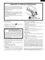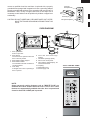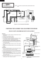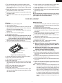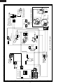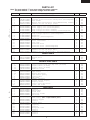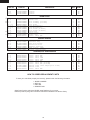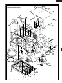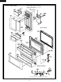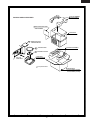
1
R- 314FS
R- 316FS
SERVICE MANUAL
S6211R316FPST
MICROWAVE OVEN
MODELS
R-314FS
R-316FS
In the interest of user-safety the oven should be restored to its original
condition and only parts identical to those specified should be used.
WARNING TO SERVICE PERSONNEL: Microwave ovens contain circuitry capable of producing very high voltage and
current, contact with following parts may result in a severe,
possibly fatal, electrical shock. (High Voltage Capacitor, High
Voltage Power Transformer, Magnetron, High Voltage Rectifier Assembly, High Voltage Harness etc..)
This is a supplemental Service Manual for Models R-314FS and R-316FS. These model are quite
similar to base model R-301FW. Use this supplemental manual together with the Base Model
Service Manual (Refer No. is S2204R301FPW/) for complete operation, service information, etc..
TABLE OF CONTENTS
Page
PRECAUTIONS TO BE OBSERVED BEFORE AND DURING SERVICING TO
AVOID POSSIBLE EXPOSURE TO EXCESSIVE MICROWAVE ENERGY ................... INSIDE FRONT COVER
BEFORE SERVICING ...................................................................................................... INSIDE FRONT COVER
WARNING TO SERVICE PERSONNEL ................................................................................................................ 1
MICROWAVE MEASUREMENT PROCEDURE ................................................................................................... 2
FOREWORD AND WARNING ............................................................................................................................... 3
PRODUCT SPECIFICATION ................................................................................................................................. 4
OVEN DIAGRAM ................................................................................................................................................... 5
OVEN SCHEMATIC ............................................................................................................................................... 6
COMPONENT REPLACEMENT AND ADJUSTMENT PROCEDURE ................................................................. 6
PICTORIAL DIAGRAM ......................................................................................................................................... 8
PARTS LIST .......................................................................................................................................................... 9
PACKING AND ACCESSORIES ......................................................................................................................... 13
This document has been published to be used for after
sales service only.
The contents are subject to change without notice.
SHARP CORPORATION
15
R - 314FS
R - 316FS
PRECAUTIONS TO BE OBSERVED BEFORE AND
DURING SERVICING TO AVOID POSSIBLE
EXPOSURE TO EXCESSIVE MICROWAVE
ENERGY
(a) Do not operate or allow the oven to be operated with the door open.
(b) Make the following safety checks on all ovens to be serviced before activating the magnetron or other
microwave source, and make repairs as necessary: (1) interlock operation, (2) proper door closing, (3)
seal and sealing surfaces (arcing, wear, and other damage), (4) damage to or loosening of hinges and
latches, (5) evidence of dropping or abuse.
(c) Before turning on microwave power for any service test or inspection within the microwave generating
compartments, check the magnetron, wave guide or transmission line, and cavity for proper alignment,
integrity, and connections.
(d) Any defective or misadjusted components in the interlock, monitor, door seal, and microwave
generation and transmission systems shall be repaired, replaced, or adjusted by procedures described
in this manual before the oven is released to the owner.
(e) A microwave leakage check to verify compliance with the Federal Performance Standard should be
performed on each oven prior to release to the owner.
BEFORE SERVICING
Before servicing an operative unit, perform a microwave emission check as per the Microwave
Measurement Procedure outlined in this service manual.
If microwave emissions level is in excess of the specified limit, contact SHARP ELECTRONICS
CORPORATION immediately @1-800-237-4277.
If the unit operates with the door open, service person should 1) tell the user not to operate the oven
and 2) contact SHARP ELECTRONICS CORPORATION and Food and Drug Administration's
Center for Devices and Radiological Health immediately.
Service personnel should inform SHARP ELECTRONICS CORPORATION of any certified unit
found with emissions in excess of 4mW/cm2. The owner of the unit should be instructed not to use
the unit until the oven has been brought into compliance.
16
R- 314FS
R- 316FS
WARNING TO SERVICE PERSONNEL
Microwave ovens contain circuitry capable of producing very high voltage and current, contact with
following parts may result in a severe, possibly
fatal, electrical shock.
(Example)
High Voltage Capacitor, High Voltage Power Transformer, Magnetron, High Voltage Rectifier Assembly, High Voltage Harness etc..
Read the Service Manual carefully and follow all
instructions.
Don't Touch !
Danger High Voltage
When the testing is completed,
1. Disconnect the power supply cord, and then remove
outer case.
2. Open the door and block it open.
3. Discharge high voltage capacitor.
4. Reconnect the leads to the primary of the power
transformer.
5. Reinstall the outer case (cabinet).
6. Reconnect the power supply cord after the outer case is
installed.
7. Run the oven and check all functions.
Before Servicing
1. Disconnect the power supply cord
outer case.
2. Open the door and block it open.
3. Discharge high voltage capacitor.
, and then remove
WARNING:RISK OF ELECTRIC SHOCK.
DISCHARGE THE HIGH-VOLTAGE
CAPACITOR BEFORE SERVICING.
After repairing
The high-voltage capacitor remains charged about 60
seconds after the oven has been switched off. Wait for 60
seconds and then short-circuit the connection of the highvoltage capacitor (that is the connecting lead of the highvoltage rectifier) against the chassis with the use of an
insulated screwdriver.
1. Reconnect all leads removed from components during
testing.
2. Reinstall the outer case (cabinet).
3. Reconnect the power supply cord after the outer case is
installed.
4. Run the oven and check all functions.
Whenever troubleshooting is performed the power supply
must be disconnected. It may, in some cases, be necessary
to connect the power supply after the outer case has been
removed, in this event,
1. Disconnect the power supply cord, and then remove
outer case.
2. Open the door and block it open.
3. Discharge high voltage capacitor.
4. Disconnect the leads to the primary of the power
transformer.
5. Ensure that the leads remain isolated from other
components and oven chassis by using insulation tape.
6. After that procedure, reconnect the power supply cord.
Microwave ovens should not be run empty. To test for the
presence of microwave energy within a cavity, place a cup
of cold water on the oven turntable, close the door and set
the power to HIGH and set the microwave timer for two (2)
minutes. When the two minutes has elapsed (timer at zero)
carefully check that the water is now hot. If the water
remains cold carry out Before Servicing procedure and reexamine the connections to the component being tested.
When all service work is completed and the oven is fully
assembled, the microwave power output should be checked
and a microwave leakage test should be carried out.
1
R - 314FS
R - 316FS
MICROWAVE MEASUREMENT PROCEDURE
A. Requirements:
1) Microwave leakage limit (Power density limit): The power density of microwave radiation emitted by a microwave oven
should not exceed 1mW/cm2 at any point 5cm or more from the external surface of the oven, measured prior to acquisition
by a purchaser, and thereafter (through the useful life of the oven), 5 mW/cm2 at any point 5cm or more from the external
surface of the oven.
2) Safety interlock switches:
Primary interlock relay and door sensing switch shall prevent microwave radiation emission in excess of the requirement
as above mentioned, secondary interlock switch shall prevent microwave radiation emission in excess of 5 mW/cm2 at
any point 5cm or more from the external surface of the oven.
B. Preparation for testing:
Before beginning the actual measurement of leakage, proceed as follows:
1) Make sure that the actual instrument is operating normally as specified in its instruction booklet.
Important:
Survey instruments that comply with the requirement for instrumentation as prescribed by the performance standard for
microwave ovens, 21 CFR 1030.10(c)(3)(i), must be used for testing.
2) Place the oven tray in the oven cavity.
3) Place the load of 275±15 ml (9.8 oz) of tap water initially at 20±5˚C (68˚F) in the center of the oven cavity.
The water container shall be a low form of 600 ml (20 oz) beaker with an inside diameter of approx. 8.5 cm (3-1/2 in.)
and made of an electrically nonconductive material such as glass or plastic.
The placing of this standard load in the oven is important not only to protect the oven, but also to insure that any leakage
is measured accurately.
4) Set the cooking control on Full Power Cooking Mode.
5) Close the door and select a cook cycle of several minutes. If the water begins to boil before the survey is completed,
replace it with 275 ml of cool water.
C. Leakage test:
Closed-door leakage test (microwave measurement)
1) Grasp the probe of the survey instrument and hold it perpendicular to the gap between the door and the body of the oven.
2) Move the probe slowly, not faster than 1 in./sec. (2.5 cm/sec.) along the gap, watching for the maximum indication on
the meter.
3) Check for leakage at the door screen, sheet metal seams and other accessible positions where the continuity of the metal
has been breached (eg., around the switches, indicator, and vents).
While testing for leakage around the door pull the door away from the front of the oven as far as is permitted by the closed
latch assembly.
4) Measure carefully at the point of highest leakage and make sure that the highest leakage is no greater than 4mW/cm2,
and that the secondary interlock switch and the primary interlock relay do turn the oven OFF before any door movement.
NOTE: After servicing, record data on service invoice and microwave leakage report.
2
R- 314FS
R- 316FS
SERVICE MANUAL
MICROWAVE OVEN
R-314FS/ R-316FS
FOREWORD
This Manual has been prepared to provide Sharp Electronics Corp. Service Personnel with Operation and Service
Information for the SHARP MICROWAVE OVENS, R-314FS and R-316FS.
The models R-314FS and R-316FS are quite similar to base model R-301FW (Refer No. is S2204R301FPW/).
It is recommended that service personnel carefully study the entire text of this manual and the base model's manual so
that they will be qualified to render satisfactory customer service.
Check the interlock switches and the door seal carefully. Special attention should be given to avoid electrical shock and
microwave radiation hazard.
WARNING
Never operate the oven until the following points are ensured.
(A) The door is tightly closed.
(B) The door brackets and hinges are not defective.
(C) The door packing is not damaged.
(D) The door is not deformed or warped.
(E) There is no other visible damage with the oven.
Servicing and repair work must be carried out only by trained service personnel.
DANGER
Certain initial parts are intentionally not grounded and present a risk of electrical shock only during servicing.
Service personnel - Do not contact the following parts while the appliance is energized;
High Voltage Capacitor, Power Transformer, Magnetron, High Voltage Rectifier Assembly, High Voltage
Harness;
If provided, Vent Hood, Fan assembly, Cooling Fan Motor.
All the parts marked “*” on parts list are used at voltages more than 250V.
Removal of the outer wrap gives access to voltage above 250V.
All the parts marked “∆” on parts list may cause undue microwave exposure, by themselves, or when they are
damaged, loosened or removed.
SHARP ELECTRONICS CORPORATION
SHARP PLAZA, MAHWAH,
NEW JERSEY 07430-2135
3
R - 314FS
R - 316FS
SPECIFICATION
ITEM
DESCRIPTION
Power Requirements
120 Volts / 13 Amperes
60 Hertz
Single phase, 3 wire grounded
Power Output
1000 watts (IEC TEST PROCEDURE)
Operating frequency of 2450MHz
Case Dimensions
Width 20-1/2"
Height 11-7/8"
Depth 16-3/4"
Cooking Cavity Dimensions
Width 14-3/4"
Height 8-3/4"
Depth 15-3/4"
1.2 Cubic Feet
Control Complement
Touch Control System
Clock ( 1:00 - 12:59 )
Timer (0 - 99 min. 99 seconds)
Microwave Power for Variable Cooking
Repetition Rate;
P-HI .................................................. Full power throughout the cooking time
P-90 .................................................................... approx. 90% of Full Power
P-80 .................................................................... approx. 80% of Full Power
P-70 .................................................................... approx. 70% of Full Power
P-60 .................................................................... approx. 60% of Full Power
P-50 .................................................................... approx. 50% of Full Power
P-40 .................................................................... approx. 40% of Full Power
P-30 .................................................................... approx. 30% of Full Power
P-20 .................................................................... approx. 20% of Full Power
P-10 .................................................................... approx. 10% of Full Power
P-0 .................................................... No power throughout the cooking time
POPCORN pad, MINUTE PLUS pad
REHEAT pad, COOK pad
DEFROST pad, Number selection pads
POWER LEVEL pad, TIMER/CLOCK pad
STOP/CLEAR pad, START pad
Oven Cavity Light
Yes
Safety Standard
UL Listed
FCC Authorized
DHHS Rules, CFR, Title 21, Chapter 1, Subchapter J
GENERAL INFORMATION
GROUNDING INSTRUCTIONS
This oven is equipped with a three prong grounding plug. It must be plugged into a wall receptacle that is properly installed
and grounded in accordance with the National Electrical Code and local codes and ordinances.
In the event of an electrical short circuit, grounding reduces the risk of electric shock by providing an escape wire for the
electric current.
WARNING: Improper use of the grounding plug can result in a risk of electric shock.
Electrical Requirements
The electrical requirements are a 120 volt 60 Hz, AC only,
15 or 20 amp. fused electrical supply. It is recommended that a separate circuit serving only this appliance be provided. When
installing this appliance, observe all applicable codes and ordinances.
A short power-supply cord is provided to reduce risks of becoming entangled in or tripping over a longer cord.
Where a two-pronged wall-receptacle is encountered, it is the personal responsibility and obligation of the customer to
4
R- 314FS
R- 316FS
contact a qualified electrician and have it replaced with a properly
grounded three-pronged wall receptacle or have a grounding adapter
properly grounded and polarized. If the extension cord must be used, it
should be a 3-wire, 15 amp. or higher rated cord. Do not drape over a
countertop or table where it can be pulled on by children or tripped over
accidentally.
Grounded
Receptacle Box
3-Pronged
Plug
Grounding Pin
CAUTION: DO NOT UNDER ANY CIRCUMSTANCES CUT OR REMOVE THE ROUND GROUNDING PRONG FROM THIS
PLUG.
3-Pronged Receptacle
OVEN DIAGRAM
7
6
9
5
2
10
8
11
12
1
4
1. Door open button.
Push to open door.
2. Door latches.
The oven will not operate unless the
door is securely closed.
3. Removable turntable support.
4. Removable turntable.
The turntable will rotate clockwise or
counterclockwise.
5. Oven lamp.
It will light when oven is operating or
door is opened.
3
6. Oven door with see-through
window.
7. Ventilation openings. (Rear)
8. Auto-Touch control panel.
9. Time display: Digital display, 99
minutes 99 seconds.
10. Coupling.
11. Waveguide cover.
12. Power supply cord
TOUCH CONTROL PANEL
COOK DEF.
NOTE:
Some one-touch cooking features such as "MINUTE PLUS" are
disabled after three minutes when the oven is not in use. These
features are automatically enabled when the door is opened and
closed or the STOP/ CLEAR pad is pressed.
5
START CHECK
R - 314FS
R - 316FS
SCHEMATIC
NOTE: CONDITION OF OVEN
1. DOOR CLOSED
2. CLOCK APPEARS ON DISPLAY
MONITOR
FUSE 20A
OVEN THERMAL
CUT-OUT
NOTE: " " indicates components with potential above 250V.
MG. THERMAL CUT-OUT
POWER
TRANSFORMER
N.O.
PRIMARY
INTERLOCK
RELAY (RY2)
CAPACITOR
0.94µF
AC 2200V
COM.
GRN
120V AC
60 Hz
B2
MONITOR
SWITCH
CONTROL UNIT
B1
DOOR
SENSING
SWITCH
OL
OVEN LAMP
RELAY (RY1)
N.O.
OVEN
LAMP
TTM
SECONDARY
INTERLOCK
SWITCH
TURNTABLE
MOTOR
RECTIFIER
FM
MAGNETRON
FAN
MOTOR
COM.
Figure O-1. Oven Schematic-Off Condition
COMPONENT REPLACEMENT AND ADJUSTMENT PROCEDURE
GRAPHIC SHEET AND MEMBRANE SWITCH REPLACEMENT
Control panel frame
Removal
1. Disconnect the power supply cord and then remove
outer case.
2. Open the door and block it open.
3. Discharge high voltage capacitor.
4. Remove the control panel assembly, referring to chapter
of CONTROL PANEL ASSEMBLY REMOVAL.
5. Remove the three (3) screws holding the control unit to
the control panel frame. And remove the control unit.
6. Remove the rubber connector from the long slit on the
control panel frame.
7. Tear away the graphic sheet from the control panel
frame.
8. Tear away the membrane switch from the control panel
frame.
Installation
1. Remove remaining adhesive on the control panel frame
surfaces with a soft cloth soaked in alcohol.
2. Tear the backing paper from the new membrane switch.
3. Insert the ribbon cable of the membrane switch into the slit
of the control panel frame.
4. Adjust the upper edge and right edge of the membrane
switch to the small depression on the surface of the
control panel frame.
5. Attach the membrane switch to the control panel frame by
rubbing with a soft cloth not to scratch.
Small backing
paper
Slit
Ribbon
cable
Small
depression
Graphic sheet
Membrane
switch
Long slit
Control panel frame
(Rear side)
Conductor portions
Ribbon cable
of membrane
switch
Rubber connector
Figure C-2. Graphic Sheet and Membrane Switch
Replacement
6
R- 314FS
R- 316FS
6. Tear the backing paper from the new graphic sheet.
7. Adjust the upper edge and right edge of the graphic sheet
to the large depression on the surface of the control
panel frame.
8. Attach the graphic sheet to the control panel frame by
rubbing with a soft cloth not to scratch.
9. Tear the small backing paper from the ribbon cable of the
membrane switch.
10. Attach the ribbon cable to the control panel frame rear
side.
12. Place the edge of the membrane switch’s ribbon cable
on the lower portion of the liquid crystal display.
12. Insert the rubber connector into the long slit on the
control panel frame.
13. Reinstall the control unit to the control panel frame with
the three (3) screws.
NOTE:
Do not contact the conductor portion of the ribbon
cable (edge) and the rubber connector directly with
your fingers. This is to avoid oxidized.
DOOR REPLACEMENT
REINSTALLATION
1. Insert each eleven (11) tab of the door decoration upper
and lower into each slit of the door frame by using a pair
of needle-nose pliers.
2. Reinstall door screen to door frame .
3. Reinstall the latch spring to the latch head. Reinstall the
latch spring to the door frame. Reinstall latch head to
door frame.
4. Reinstall door panel to door frame by fitting eight (8) tabs
of door frame to eight (8) holes of door panel.
5. Put sealer film on door panel. Refer to “Sealer Film”
about how to handle new one.
6. Catch two (2) pins of door panel on two (2) hole of upper
and lower oven hinges.
7. Reinstall choke cover to door panel by pushing.
Note: After any service to the door;
(A) Make sure that door sensing switch and secondary
interlock switch are operating properly. (Refer to
chapter “Test Procedures”.).
(B) An approved microwave survey meter should be
used to assure compliance with proper microwave
radiation emission limitation standards.
After any service, make sure of the following :
1. Door latch heads smoothly catch latch hook through
latch holes and that latch head goes through center of
latch hole.
2. Deviation of door alignment from horizontal line of cavity
face plate is to be less than 1.0mm.
3. Door is positioned with its face pressed toward cavity
face plate.
4. Check for microwave leakage around door with an
approved microwave survey meter. (Refer to Microwave
Measurement Procedure.)
Note: The door on a microwave oven is designed to act as
an electronic seal preventing the leakage of
microwave energy from oven cavity during cook
cycle. This function does not require that door be airtight, moisture (condensation)-tight or light-tight.
Therefore, occasional appearance of moisture, light
or sensing of gentle warm air movement around
oven door is not abnormal and do not of themselves
indicate a leakage of microwave energy from oven
cavity.
REMOVAL
1. Disconnect the power supply cord.
2. Open the door slightly.
3. Insert a putty knife (thickness of about 0.5mm) into the
gap between the choke cover and door frame as shown
in Figure C-4 to free engaging parts.
4. Pry the choke cover by inserting a putty knife as shown
Figure C-4.
5. Release choke cover from door panel.
6. Now choke cover is free.
NOTE: When carrying out any repair to the door, do not
bend or warp the slit choke (tabs on the door
panel assembly) to prevent microwave leakage.
7. Release two (2) pins of door panel from two (2) holes of
upper and lower oven hinges by lifting up.
8. Now, door panel with door frame is free from oven cavity.
Door Frame
Putty Knife
Choke Cover
Figure C-4. Door Disassembly
9. Release door panel from eight (8) tabs of door frame.
10.Now, door panel with sealer film is free.
11.Tear sealer film from door panel.
12.Now, door panel is free.
13.Slide latch head upward and remove it from door frame
with releasing latch spring from door frame and latch
head.
14.Now, latch head and latch spring are free.
15.Remove door screen from door frame.
16.Now, door screen is free.
17.Unfold each eleven (11) tab of the door decoration upper
and lower by using a pair of needle-nose pliers. Now the
door frame is loose.
7
1
H
2
CN-B
3
8
4
R
E
D
R
E
D
Y
L
W
B
L
K
N.O.
RY1
GRY
WHT
COM.
5
GRY
GRY
TURNTABLE
MOTOR
BLK
WHT
Figure S-1. Pictorial Diagram
BLK
MONITOR
FUSE
&
HOLDER
BLK
FAN MOTOR
WHT
RED
WHT
WHT
C
WHT
WHT
GRY
BLK
GRY
BLK
NOTE:
The neutral (WHT) wire must be
connected to the terminal with "N"
mark on the power supply cord.
POWER SUPPLY
CORD 120V 60Hz
N
POWER
TRANSFORMER
MAGNETRON
HIGH VOLTAGE
CAPACITOR
HIGH VOLTAGE COMPONENTS
BLK
THERMAL
CUT-OUT (MG)
H
4
COM.
SECONDARY NO
INTERLOCK
SWITCH
MONITOR
SWITCH
N.C.
RED
BLK
WHT
BLK
3
COM.
RY2
1 GRN
E
COM.
T1
CN-B
2 ORG
BLK
YLW
GRY
OVEN LAMP
THERMAL
CUT-OUT (OVEN)
2
PRIMARY
INTERLOCK
RELAY
N.O.
1
G
2
CONTROL UNIT
GRN
ORG
A
(To oven cavity front flange.)
GRN
GRN
F
N.O.
NOTE:
The grounding conductor of
the power supply cord has
been grounded by power
supply cord fixing screw.
The screw must allways be
kept tight.
B
COM.
DOOR
SENSING
SWITCH
D
BLK
1
H.V.
RECTIFIER
BLK
R - 314FS
R - 316FS
5
6
A
6
B
C
D
E
F
G
H
R- 314FS
R- 316FS
PARTS LIST
Note: The parts marked “∆” may cause undue microwave exposure.
The parts marked “*” are used in voltage more than 250V.
REF. NO.
PART NO.
DESCRIPTION
Q'TY
CODE
2
2
1
1
1
1
1
1
1
1
1
1
1
1
1
1
1
1
1
1
1
1
1
1
AG
AH
AG
AS
AK
AS
AV
AN
AK
AP
AV
AV
BL
BK
AV
-BM
AL
AS
AW
AS
AQ
AH
AP
1
1
1
BE
AX
AC
1
1
1
1
1
1
1
1
1
1
1
1
1
1
1
3
BB
BB
AW
AW
AQ
AS
AK
AU
AB
BF
AW
AH
AU
AL
AU
AA
1
1
1
1
1
1
1
1
1
1
2
1
1
1
1
1
1
1
AE
AF
AQ
AC
AL
AZ
-AU
AB
AG
AB
AE
AC
AE
AF
AF
AB
AH
ELECTRIC PARTS
*
*
*
*
∆*
∆*
*
1- 1
1- 1
1- 2
1- 3
1- 4
1- 5
1- 5
1- 5
1- 6
1- 6
1- 7
1- 7
1- 8
1- 8
1- 9
1- 9
1-10
1-11
1-12
1-12
1-12
1-12
1-13
1-13
QSW-MA147WRZZ
QSW-MA137WRE0
QFSHDA009WRE0
FFS-BA023WRK0
RTHM-A127WRZZ
FACCDA089WREZ
FACCDA082WRE0
FACCDA086WREZ
FH-DZA092WRK0
FH-DZA088WRK0
RC-QZA211WRE0
RC-QZA286WRZZ
RV-MZA308WRZZ
RV-MZA288WRE0
RMOTEA383WRE0
RMOTEA408WRZZ
RTRN-A664WRZZ
RLMPTA082WRZZ
RMOTDA211WRE0
RMOTDA186WRE0
RMOTDA161WRE0
RMOTDA229WRE0
RTHM-A120WRE0
RTHM-A080WRE0
Secondary interlock switch/door sensing switch
Secondary interlock switch/door sensing switch (Interchangeable)
Fuse holder
Monitor fuse 20A and monitor switch(AM51620C53Y1) assembly
Thermal cut-out 125 deg.C (Oven)
Power supply cord
Power supply cord (Interchangeable)
Power supply cord (Interchangeable)
High voltage rectifier assembly
High voltage rectifier assembly (Interchangeable)
High voltage capacitor
High voltage capacitor (Interchangeable)
Magnetron
Magnetron (Interchangeable)
Fan motor
Fan motor (Interchangeable) for production use
Power transformer
Oven lamp
Turntable motor
Turntable motor (Interchangeable)
Turntable motor (Interchangeable)
Turntable motor (Interchangeable)
Thermal cut-out 145 deg.C (MG.)
Thermal cut-out 145 deg.C(MG.) (Interchangeable)
2- 1
2- 2
2- 3
GCABUA861WRPZ
GDAI-A343WRWZ
GLEGPA074WRE0
Outer case cabinet
Bottom plate
Foot
3- 1
3- 1
3- 1-1
3- 1-1
3- 1-2
3- 2
3- 2-1
3- 2-2
3- 3
3- 4
3- 5
3- 6
3- 7
3- 8
3- 9
3-10
FPNLCB665WRKZ
FPNLCB666WRKZ
PSHEPA850WRZZ
PSHEPA852WRZZ
QSW-KA021DRZZ
FBTN-A145WRKZ
JBTN-B185WRFZ
HDECQA229WRRZ
MSPRCA050WRE0
DPWBFC248WRUZ
PSHEPA851WREZ
QCNC-A015WRZZ
RLCDSA108DRZZ
GMADIA116WRRZ
HDECQA234WRPZ
XEPSD30P08XS0
Control panel frame with key unit [R-314FS]
Control panel frame with key unit [R-316FS]
Graphic sheet [R-314FS]
Graphic sheet [R-316FS]
Membrane switch
Open button assembly
Open button
Button decoration
Open button spring
Control unit
LED sheet
Rubber connector
Liquid crystal display
Display window
Conrol panel decoration
Screw; 3mm x 8mm
4- 1
4- 2
4- 3
4- 4
4- 5
4- 6
4- 7
4- 8
4- 9
4-10
4-11
4-12
4-13
4-14
4-15
4-16
4-17
4-18
PCUSUA235WRP0
PPACGA084WRF0
PHOK-A114WRF0
LBNDKA099WRW0
NFANJA029WRE0
PDUC-A790WRWZ
*************
LANGFA194WRW0
PCUSGA560WREZ
MLEVPA233WRF0
PCUSUA212WRP0
NCPL-A053WRFZ
PCUSUA511WRP0
PCOVPA349WRE0
PCUSGA339WRP0
PCUSGA399WRE0
PCUSUA512WRP0
PCUSGA321WRP0
Cushion
TTM packing
Latch hook
Capacitor holder
Fan blade
Fan duct
Oven cavity (Not a replaceable part)
Chassis support
Cushion
Switch lever
Cushion
Coupling
Cushion
Waveguide cover
Cushion
Cushion
Cushion
Cushion
CABINET PARTS
CONTROL PANEL PARTS
OVEN PARTS
∆
∆
9
R - 314FS
R - 316FS
REF. NO.
4-19
4-20
4-21
4-20
PART NO.
PCUSUA474WRP0
PCUSGA562WREZ
PCUSUA190WRP0
PCUSUA191WRP0
DESCRIPTION
Cushion
Cushion
Cushion
Cushion
Q'TY
CODE
2
1
1
1
AC
AC
AC
AC
1
1
1
1
1
1
1
1
1
1
1
1
2
BB
AH
BP
BP
AX
AU
AU
AT
AT
AG
AC
AH
AA
1
1
1
1
1
1
1
AQ
AR
AU
AP
AB
AC
AC
6
1
4
1
1
17
1
1
2
2
4
AA
AA
AA
AA
AA
AA
AA
AA
AC
AA
AA
DOOR PARTS
∆ 5- 1
∆
∆
∆
∆
555555555555-
2
3
3
3-1
3-2
3-3
4
4
5
6
7
8
FDORFA332WRT0
PSHEPA382WRE0
CDORFA962WRKZ
CDORFA963WRKZ
GWAKPA869WRFZ
HDECQA230WRRZ
HDECQA231WRRZ
HPNL-A781WRRZ
HPNL-A783WRRZ
LSTPPA188WRF0
MSPRTA187WRE0
GCOVHA405WRF0
XCPSD40P08000
Door panel
Sealer film
Door assembly [R-314FS]
Door assembly [R-316FS]
Door frame
Door decoration U
Door decoration L
Door screen [R-314FS]
Door screen [R-316FS]
Latch head
Latch spring
Choke cover
Screw : 3mm x 6mm
6666666-
1
2
3
4
5
6
7
FROLPA079WRK0
NTNT-A051WRE0
FW-VZB905WRRZ
TINSEA930WRRZ
PZET-A012WRE0
TCAUAA265WRRZ
TCAUAA254WRR0
Turntable support
Turntable tray
Main wire harness
Instruction book
Terminal insulator
DHHS caution label
Monitor caution label
MISCELLANEOUS
SCREWS,NUTS AND WASHERS
7- 1
7- 2
7- 3
7- 4
7- 5
7- 6
7- 7
7- 7
7- 8
7- 9
7-10
XHPSD40P08K00
XHPSD30P06000
XHTSD40P08RV0
XHTSD40P12RV0
XOTSD40P12RV0
XOTSD40P08000
XOTSF40P08000
XOTSE40P08000
LX-CZA070WRE0
LX-CZ0052WRE0
XHPSD40P08000
Screw :
Screw :
Screw :
Screw :
Screw :
Screw :
Screw :
Screw :
Special
Special
Screw :
4mm x
3mm x
4mm x
4mm x
4mm x
4mm x
4mm x
4mm x
screw
screw
4mm x
8mm
6mm
8mm
12mm
12mm
8mm
8mm [R-301FK]
8mm [R-301FW]
(Torx tamper proof screw)
8mm
HOW TO ORDER REPLACEMENT PARTS
To have your order filled promptly and correctly, please furnish the following information.
1. MODEL NUMBER
2. REF. NO.
3. PART NO.
4. DESCRIPTION
Order Parts from the authorized SHARP parts Distributor for your area.
Defective parts requiring return should be returned as indicated in the Service Policy.
10
R- 314FS
R- 316FS
2
1
4
3
7-6
2-1
OVEN AND CABINET PARTS
6
5
7-8
A
A
7-6
4-19
7-10
B
4-17
B
7-8
4-9
4-20
4-22
1-4
6-7
1-8
4-13
7-7
4-21
C
C
6-6
4-11
4-7
7-3
1-5
7-6
D
D
7-4
4-19
7-1
4-12
1-7
4-11
4-15
1-1
E
7-9
4-14
6-2
1-6
4-4
4-18
4-3
7-1
6-1
4-8
7-6
1-3
1-12
F
E
1-13
1-2
4-10
4-2
7-6
7-2
4-5
1-1
7-6
7-3
1-10
F
7-5
7-1
2-2
4-1
4-6
4-16
1-11
1-9
G
G
7-1
7-6
7-6
H
H
7-6
7-6
2-3
1
2
4
3
11
5
6
R - 314FS
R - 316FS
2
1
CONTROL PANEL PARTS
6
5
Before attaching Control unit to Control
panel, foil side of Control unit must be
cleaned by ethyl-alcohol.
3-9
A
4
3
A
3-8
3-10
3-1
3-1-1
B
B
3-6
3-4
3-1-2
C
C
DOOR PARTS
5-7
3-2
3-3
3-2-1
D
D
5-2
3-2-2
5-3
5-1
5-3-1
E
E
5-3-2
5-8
5-4
5-3-3
F
F
5-5
5-6
G
G
MISCELLANEOUS
6-5
6-3
H
H
Actual wire harness may be different from illustration.
1
2
4
3
12
5
6
R- 314FS
R- 316FS
2
1
4
3
6
5
A
A
TOP PAD ASSEMBLY
PACKING AND ACCESSORIES
FPADBA492WRKZ
DOOR PROTECTION SHEET
B
B
SPADPA204WRE0
PLASTIC BAG
SSAKHA034WRE0
C
6- 4
C
INSTRUCTION BOOK
& PRINTING MATTER
6- 2
BOTTOM PAD ASSEMBLY
TURNTABLE TRAY
FPADBA493WRKZ
6- 1 TURNTABLE SUPPORT
D
D
TRAY PACK
INTO THE
OVEN CAVITY
SPADFA527WREZ
Not replaceable items.
E
E
PACKING CASE
FPAK-A435WRKZ [R-314FS]
FPAK-A436WRKZ [R-316FS]
F
F
G
G
H
H
1
2
4
3
13
5
6
R - 314FS
R - 316FS
COPYRIGHT © 2002 BY SHARP CORPORATION
ALL RIGHTS RESERVED.
No part of this publication may be reproduced,
stored in retrieval systems, or transmitted in any
form or by any means, electronic, mechanical,
photocopying, recording, or otherwise, without
prior written permission of the publisher.
2002 SHARP CORP. (2S1.700E) Printed in U.S.A
14