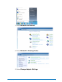
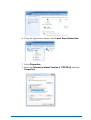
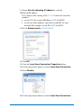
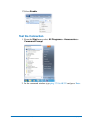
1
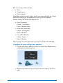
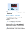
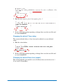
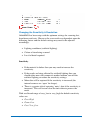
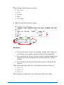
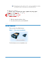
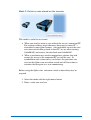
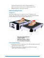
Delcam iQube 2010
Reference Help
Copyright © 2009 - 2010 Delcam plc. All rights reserved
Delcam plc has no control over the use made of the software described in
this manual and cannot accept responsibility for any loss or damage
howsoever caused as a result of using the software. Users are advised that
all the results from the software should be checked by a competent
person, in accordance with good quality control procedures.
The functionality and user interface in this manual is subject to change
without notice in future revisions of software.
The software described in this manual is furnished under licence
agreement and may be used or copied solely in accordance with the terms
of such licence.
Delcam plc grants permission for licensed users to print copies of this
manual or portions of this manual for personal use only. Schools, colleges
and universities that are licensed to use the software may make copies of
this manual or portions of this manual for students currently registered for
classes where the software is used.
Acknowledgements
This documentation references a number of registered trademarks and
these are the property of their respective owners. For example, Microsoft
and Windows are either registered trademarks or trademarks of Microsoft
Corporation in the United States.
Delcam iQube Version 2010. Published on 01 June 2010
Contents
Introduction
1
Compliance
2
FCC ................................................................................................................2
WEEE.............................................................................................................2
Technical Specifications
4
Electrical Specifications ................................................................................4
Permissible Environmental Conditions .........................................................4
Temperature Range ........................................................................................4
Safety Precautions
5
Understanding Warning Terms ......................................................................5
Understanding Precaution Terms...................................................................6
Warnings ........................................................................................................6
Cautions .........................................................................................................8
iQube Parts List
Hardware Diagrams
9
10
Hardware diagram - legend..........................................................................11
Setting up
12
Remove the Cover........................................................................................13
Electrical Connection ...................................................................................13
Network Connection ....................................................................................15
Power-up the Scanner ..................................................................................15
Connecting to the Scanner ...........................................................................17
Test the Connection .............................................................................21
Software Installation
Delcam iQube 2010 Reference Help
23
Contents • i
System Requirements ..................................................................................23
Installation....................................................................................................23
Test ...............................................................................................................24
Using the Delcam Orthotic Insoles Software 26
Jobs Page
27
Adding a Job ................................................................................................27
Deleting a Job ..............................................................................................28
Scan Page
29
Scan Model ..................................................................................................31
Scan Settings ................................................................................................32
Changing the Default Scan Settings ...................................................34
Scan Mode ...................................................................................................38
Export Page
41
Scanning Procedures
44
Scanning a Foot............................................................................................44
Scanner Setup (Foot) ...........................................................................45
Orientation & Location (Foot) .............................................................47
Scan Settings (Foot) .............................................................................47
Scanning a Foam Box Impression ...............................................................48
Scanner Setup (Foam Box Impression) ...............................................49
Orientation & Location (Foam Box Impression) ................................51
Scan Settings (Foam Box Impression) ................................................52
Scanning a Cast ............................................................................................53
Scanner Setup (Cast)............................................................................53
Orientation and Location (Cast) ..........................................................53
Scan Settings (Cast) .............................................................................54
Maintenance and Handling
55
Maintenance .................................................................................................56
Handling .......................................................................................................56
Manufacturer Details
57
Index
59
ii • Contents
Delcam iQube 2010 Reference Help
Delcam iQube 2010 Reference Help
Contents • iii
Introduction
iQube is a simple but powerful 3D scanner specifically created for use in
designing custom orthotic insoles.
iQube provides you with a versatile tool to produce high quality orthotics
and insoles and improve the quality of service you are able to provide to
your clients.
It allows you to scan what you want, when you want and how you want.
Whether you need to scan a foot, a cast or a foam box impression, iQube
can produce a high quality 3D image in approximately 3 seconds, saving
you time and improving the quality of the output.
Using technology developed for the Aerospace industry, the iQube
obtains a high level of detail using laser and multi camera configuration
to produce a full colour 3D image that is accurate to within a hair’s
breadth. This high level of accuracy means that you get the custom
orthotic right first time and minimise the inconvenience to your client.
iQube allows the foot to be scanned in non, partial and full weight
bearing positions, allowing flexibility dependant upon the patient’s needs.
The scanner is lightweight and compact, making it fully portable and
comes with an optional carry case, allowing you to use it at different
locations and transport it with ease. Once you have scanned the item you
want, you can design and manufacture the custom orthotic insole using
Delcam’s OrthoModel software or your existing orthotic CADCAM
software.
Delcam iQube 2010 Reference Help
Introduction • 1
Compliance
FCC (see page 2)
WEEE (see page 2)
FCC
This equipment has been tested and found to comply with the limits for a
Class A digital device, pursuant to part 15 of the FCC Rules. These limits
are designed to provide reasonable protection against harmful
interference when the equipment is operated in a commercial
environment. This equipment generates, uses, and can radiate radio
frequency energy and, if not installed and used in accordance with the
instruction manual, may cause harmful interference to radio
communications. Operation of this equipment in a residential area is
likely to cause harmful interference in which case the user will be
required to correct the interference at his own expense.
Also please note the following statement that is on a sticker adhered to
the base of the scanner body:
This device complies with part 15 of the FCC Rules. Operation is subject
to the following two conditions: (1) This device may not cause harmful
interference, and (2) this device must accept any interference received,
including interference that may cause undesired operation.
WEEE
WEEE stands for Waste Electrical and Electronic Equipment and
refers to an E.U. directive regulating the disposal of electrical or
electronic equipment, including all components, sub-assemblies and
consumables, which are part of the products at the time of discarding.
2 • Compliance
Delcam iQube 2010 Reference Help
European Directive 2002/96/EC on Waste Electrical and Electronic
Equipment (the WEEE Directive) stipulates that WEEE is now subject
to regulations designed to prevent the disposal of such waste and to
encourage design and treatment measures to minimize the amount of
waste that is placed into the waste system.
The purpose of this legislation is to preserve, protect and improve the
quality of the environment, protect human health, and stimulate the
practical use of natural resources. Specifically, the WEEE Directive
requires that producers of electrical and electronic equipment be
responsible for the collection, reuse, recycling and treatment of WEEE
which the Producer places on the EU market after August 13, 2005.
As an importer of electrical and electronic equipment (EEE), we have
endeavoured to meet these environmental responsibilities for managing
WEEE. The following information is to educate our customers about the
WEEE collection process.
In order to avoid any potential dissemination of hazardous substances into
the environment, the product has been labelled with the WEEE symbol
(see below) in order to alert the end-user that it should be disposed of
within the proper waste management system. That system will recycle,
reuse, and dispose of materials from this product in an environmentally
sound way.
The symbol found on the Delcam product label, indicates that the product
meets the European Directive 2002/96/EC on Waste and Electronic
Equipment. This symbol, only applicable in European Union countries,
indicates that when this product reaches the end of its life it should not be
disposed of with normal household or municipal waste, but in an
established waste stream for WEEE.
Each EU Member State country has established a system for the
collection, disposal, and recycling of WEEE. End-users in the EU should
contact their local waste administration system for collection instructions
concerning this product.
Delcam iQube 2010 Reference Help
Compliance • 3
Technical
Specifications
The following sections comprise the Technical Specifications:
Electrical Specifications (see page 4)
Permissible Environmental Conditions (see page 4)
Temperature Range (see page 4)
Electrical Specifications
Voltage AC 100 V – 240 V / 120 W
Main supply voltage fluctuations up to +/- 10% of the nominal
Permissible Environmental Conditions
For Indoor Use Only
Maximum relative humidity 80% for temperatures up to 31 deg C
decreasing linearly to 50% relative humidity at 40 deg C
Vibration (55 to 2000Hz): <= 100ms/s*s EN 60 068-2-6
Shock (6ms): <= 1000ms/s*s
Altitude: Up to 2000m
Temperature Range
Storage Temperature: 5 deg C to 40 deg C
4 • Technical Specifications
Delcam iQube 2010 Reference Help
Ambient Temperature required for measuring operation: 20 deg C
+/- 10 deg C
Safety Precautions
This unit has been designed and tested to ensure reasonable personal
protection and protection of the surrounding area against damage, and has
been supplied in safe condition. The following precautions must be
observed by the user to ensure safe operation and to retain the instrument
in safe condition.
If this instrument is used in a manner not specified by the manufacturer,
the protection provided by this instrument may be impaired.
Different safety precautions are described in the following sections:
Understanding Warning Terms (see page 5)
Understanding Precaution Terms (see page 6)
Warnings (see page 6)
Cautions (see page 8)
Understanding Warning Terms
Levels of injuries or damages that may occur when the instrument is used
incorrectly without paying attention to descriptions of warnings or
cautions are shown below.
Notation
Description
DANGER
Delcam iQube 2010 Reference Help
Indicates the potentially hazardous
situations which, if not heeded, should
result in death or serious injury.
Safety Precautions • 5
WARNING
CAUTION
Indicates the potentially hazardous
situations which, if not heeded, could
result in death or serious injury.
Indicates the potentially hazardous
situations which, if not heeded, could
result in minor or moderate injury or
instrument damage.
Understanding Precaution Terms
Precautions that must be adhered to are shown below:
Notation
Description
Pay Attention
Do not perform
You must perform
Laser Safety Notice
Warnings
The following warnings highlight potentially hazardous situations which,
if not heeded, could result in death or serious injury.
Do not attempt to damage the power cable and
power plug.
Do not damage, modify, forcefully bend, twist,
stretch, nor bind the power cable and power plug.
Do not put heat apparatus close to them nor a
heavy object on them.
Using a damaged power cable or power plug may
cause an electric shock, short-circuit, smoke and
fire.
6 • Safety Precautions
Delcam iQube 2010 Reference Help
Clean dust off the power plug periodically.
Any dust on the plug may cause insulation failure
due to absorbed moisture. It may further result in
smoke and fire.
Disconnect the power plug to wipe it with a dry
cloth.
Operate the unit at the specified voltage.
This instrument must be operated within the AC
supply voltage range as indicated on the rear panel
and / or an attached tag to the power cable on
which the voltage is marked, and frequency of
power supply must be 50 or 60 Hz. Otherwise,
smoke or fire may break out.
Nominal
Range
AC 100 V –
240 V
90 V – 260 V
Never insert or pull out the power cable with a wet
hand.
Such an attempt may cause an electric shock.
Do not use the instrument in an explosive
environment.
Never use the instrument in rooms having
flammable or volatile gas or vapour, otherwise, an
explosion may occur or a fire may break out.
Do not disassemble the instrument.
Disassembly may cause an electric shock or
malfunction.
Removal of panels is likely to expose live parts. If
any adjustment, maintenance or repair is
inevitable, it shall only be carried out by a
qualified service personnel who is aware of the
hazard involved.
Laser Light – Do not stare into beam or view
directly with optical instruments
Laser light can damage your eyes.
Delcam iQube 2010 Reference Help
Safety Precautions • 7
Do not exceed maximum weight of glass
Maximum Weight: 200KG
Do not jump on the glass.
Cautions
The following cautions highlight the potentially hazardous situations
which, if not heeded, could result in minor or moderate injury or
instrument damage.
Use the specified fuse.
Verify that the correct fuse is installed before
supplying power.
Do not use unauthorized fuses. Otherwise, smoke
or fire may break out.
Nominal
Fuse rating
AC 100 V – 240 V
3.14A 250V (T)
Do not use the device if it appears broken.
Otherwise, an electric shock, smoke or fire may
break out.
Immediately turn off the instrument and disconnect
the power cable. Then contact the dealer or
representative from whom you purchased the
instrument.
This instrument is equipped with a Class II laser.
Class II laser products are normally not capable of
causing eye injuries, but can still be quite
hazardous due to glare and temporary flash
blindness. The human blink reflex occurs within
0.25 seconds of exposure to the Class II laser
beam, provides adequate protection. However, it is
possible to overcome the blink response and stare
into the Class II laser long enough to damage the
eye.
8 • Safety Precautions
Delcam iQube 2010 Reference Help
iQube Parts List
Scanner
1 x iQube 3D Scanner
1 x Scanner Cover
1 x AC Power Cable (regional)
1 x Network cable
Software
1 x Custom Orthotic Insoles installation CD
1 x Software Dongle
Documentation
1 x User Manual
Foam Box Scan Aids
45mm Foam Box Lifters (x4)
40mm Lifter Extensions (x2)
Maintenance Kit
Glass Cleaner Sachets
Delcam iQube 2010 Reference Help
iQube Parts List • 9
Hardware Diagrams
10 • Hardware Diagrams
Delcam iQube 2010 Reference Help
Hardware diagram - legend
The following items are shown on the hardware diagrams:
Main Unit
1.
Scanner body
2.
Tempered Glass Screen
3.
iQube Scan Activation Switch
4.
Electrical Panel
5.
AC Power Cable Connection
6.
Power Switch
7.
LAN Cable Connection
Delcam iQube 2010 Reference Help
Hardware Diagrams • 11
8.
USB 1 Connection (DO NOT
USE)
9.
USB 2 Connection (DO NOT
USE)
10.
Screen Release Entry
11.
End Lifting Handles
12.
Side Handle
Lid
13.
Lid
14.
Lid Clips (x4)
15.
Standing Surface
16.
Support Legs
Auxiliary Items
AC Power Cable (Regional)
17.
18. Network Cable
19. Custom Orthotic Insoles
installation CD
20. Software Dongle
21. 45mm Foam Box Lifters (x5)
22. 40mm Lifter Extensions (x5)
23. Glass Cleaner Sachets + Duster
Setting up
12 • Setting up
Delcam iQube 2010 Reference Help
The following sections give details on setting up for a scan:
Remove the Cover (see page 13)
Electrical Connection (see page 13)
Network Connection (see page 15)
Power-up the Scanner (see page 15)
Connecting to the Scanner (see page 17)
Remove the Cover
1. Place the scanner onto a flat surface.
2. Unfasten the clips (14) from the scanner body (1) to release the lid
(13).
3. Extend the support legs (16) and place adjacent to the scanner body
(1).
Electrical Connection
CAUTION
Delcam iQube 2010 Reference Help
Setting up • 13
Always use the AC power cord supplied as a standard accessory with the
scanner, and connect it to an AC outlet (100-240 V, 50/60 Hz). Failure to
do so may damage the scanner, causing a fire or electric shock.
1. Set the Power Switch (6) on the end panel to OFF (“0”)
CAUTION
If the AC power cord is connected to an AC outlet with the power
switch set to ON (“|”), damage to the scanner or computer may
result. Before connecting the AC power cord, always make sure
that the power switch is set to OFF.
2. Connect the AC Power Cable (17) to the scanner’s AC power
connector (5) located on the electrical panel (4).
3. Plug the other end of the AC power cable to an AC outlet.
CAUTION
Be sure to connect the AC power cord’s plug to an AC outlet that
has a grounding terminal.
Make sure that the AC outlet is located near the scanner and that
the scanner's AC power cord’s plug can be easily connected and
disconnected.
Do not bend, twist or pull the AC power cord excessively. Do not
place heavy items on it, scratch or modify it. Doing so may damage
it, resulting in fire or electric shock.
If you are not going to use the scanner for a long time, disconnect
the AC power cord from the AC outlet. If dirt or water accumulates
on the prongs of the AC power cord’s plug, it may cause a fire. If
there is any dirt or water on the prongs, it must be removed.
14 • Setting up
Delcam iQube 2010 Reference Help
When disconnecting the AC power cord’s plug, always hold the
plug and pull it to remove it. Never pull the AC power cord itself as
it may be damaged, resulting in fire or electric shock. Also do not
insert or disconnect the AC power cord’s plug with wet hands.
Doing so may cause electric shock.
Network Connection
In order to drive the scanner from your PC it must be connected to the
scanner using a network cable.
1. Plug one end of the network cable (18) into the network port of the
scanner (7)
2. Plug the other of the network cable into your network hub or the
network port on your computer.
Power-up the Scanner
Set the scanner Power Switch (6) to ON ( | ).
Delcam iQube 2010 Reference Help
Setting up • 15
The iQube logo located on the tempered glass screen (2) will glow blue.
After approximately 1 minute the scanner will produce a test movement.
Following this, the iQube scan activation switch (3) will change from red
to glowing green.
16 • Setting up
Delcam iQube 2010 Reference Help
CAUTION
When turning the power ON again after it has just been turned OFF wait
at least 10 seconds before doing so. Failure to observe this may result in
malfunction or breakdown of the scanner.
Connecting to the Scanner
To operate the scanner from your PC the network connection between the
two must be configured. For the two devices to communicate, the IP
address of your PC must be set within the same domain as that of the
scanner.
1. Log into your own PC or the PC provided with the scanner
Please ensure you have system permissions to install
software.
2. From the windows menu select Control Panel.
Delcam iQube 2010 Reference Help
Setting up • 17
3. Select Network and Internet.
4. Select Network & Sharing Center.
5. Select Change Adapter Settings.
18 • Setting up
Delcam iQube 2010 Reference Help
6. Using the right mouse button, select Local Area Connection.
7. Select Properties.
8. Select the Internet protocol Version 4 (TCP/IPv4) and click
Properties.
Delcam iQube 2010 Reference Help
Setting up • 19
9. Ensure Use the following IP address is selected.
10.Enter the IP address.
Use a unique value starting with 172.16.40 where the last three
numbers:
are not 222 (the scanner IP address is 172.16.40.222)
are not any other numbers equivalent to other PC on your
network. For example, set the PC to 172.16.40.225
11.Set the Subnet mask to 255.255.255.0
12.Click OK.
13.Close the Local Area Connection Properties dialog.
14.Use the right mouse button to select Local Area Connection.
15.Select Disable.
16.Use the right mouse button to select Local Area Connection.
20 • Setting up
Delcam iQube 2010 Reference Help
17.Select Enable.
Test the Connection
1. From the Start menu select All Programs > Accessories >
Command Prompt
2. In the command window type ping 172.16.40.222 and press Enter.
Delcam iQube 2010 Reference Help
Setting up • 21
The following message should be displayed, denoting that the PC
and scanner are talking to each other.
You are now ready to install the Delcam Orthotic Insoles
Software.
22 • Setting up
Delcam iQube 2010 Reference Help
Software Installation
Use the following sections to guide you through the installation and
testing process:
System Requirements (see page 23)
Installation (see page 23)
Test (see page 24)
System Requirements
To use the scanner your computer must have a minimum specification as
follows:
Dual Processor - 2.2GHz
2GB Dual Channel Memory
160GB Hard Drive
Ethernet Network Adapter
Windows ® 7
512 MB NVIDIA® GeForce™ 9600M GS Graphic Card
DVD Drive
We do not recommend any Intel integrated graphics or ATI cards.
Installation
If you purchased a PC with the scanner, the software should already be
installed and ready to use (see Using the Delcam Orthotic Insoles
software (see page 26).)
Delcam iQube 2010 Reference Help
Software Installation • 23
Please see System Requirements (see page 23) for minimum hardware
specification.
To install the software
1. Log into your own PC or the PC provided with the scanner
Please ensure you have system permissions to install software
2. Insert the Custom Orthotic Insoles software installation CD (19)
into the computer CD ROM drive and close.
3. Follow the steps on the installation wizard
Before you are able to run the software you must insert the
software dongle and copy the software authorization file (obtained
from your Sales partner) to the required location.
4. Insert the software dongle into a USB socket on your PC
5. Copy the software authorization file to the following location:
C:\Program Files\Common Files\Delcam
6. Restart the PC and login.
Test
This section assumes that the software dongle is connected and the
product authorization file has been copied to the correct location
1. Double click on the Delcam Orthotic Insoles icon on your desktop.
24 • Software Installation
Delcam iQube 2010 Reference Help
By default the software will display the Jobs Page. When the
software is used for the first time, there are no jobs to display, so
the the screen will appear as follows:
Delcam iQube 2010 Reference Help
Software Installation • 25
Using the Delcam
Orthotic Insoles
Software
This section provides detailed information regarding the operation of the
software. To get the best results from scanning a foot, foam box or cast
please see the relevant sections within the ‘Scanning’ chapter.
1. Double click on the Delcam Orthotic Insoles icon located on your
desktop.
2. Use the following sections for information on using the software:
Jobs Page (see page 27)
Scan Page (see page 29)
Export Page (see page 41)
Scanning Procedures (see page 44)
26 • Using the Delcam Orthotic Insoles Software
Delcam iQube 2010 Reference Help
Jobs Page
To scan a patient’s foot, foam box or cast, a job must be created with the
required information. Use the following sections for information on using
the Jobs page:
Adding a Job (see page 27)
Deleting a Job (see page 28)
Adding a Job
1. Click the New Job icon
The Patient/Podiatrist dialog is displayed:
2. Add the following details:
First Name
Last name
Delcam iQube 2010 Reference Help
Jobs Page • 27
Email
Telephone Number
These details will be added to the Job line and the job information
is automatically stored.
These details will be added to the Job line and the job information
is automatically stored.
Deleting a Job
1. Select the job you wish to delete.
2. Click Delete Job button.
The job and its associated scan files will be deleted from the
software.
Once deleted a job cannot be retrieved
28 • Jobs Page
Delcam iQube 2010 Reference Help
Scan Page
1. Ensure that the details of the job have been added (see page 27).
2. Click the iQube scan button at the top of the screen.
The following Scan Page is displayed:
3. Place the patient’s foot, foam box impression or cast onto the
scanner surface.
4. Select one of the three Scan Model buttons (see page 31).
Delcam iQube 2010 Reference Help
Scan Page • 29
5. Select one of the three Scan Mode buttons (see page 38).
6. Click Scan Left Foot or Scan Right Foot panels as appropriate.
7. Depending upon the selected scan mode the following will happen:
Take Scan Immediately: A scan will be immediately performed,
followed by processing and retrieval into the software.
Retrieve scan stored on scanner: A previous scan taken using
the iQube scan activation switch will be retrieved into the
software.
The iQube scan activation switch will glow red while the
scan and subsequent processing is being performed. Do not
attempt to perform any other software operations during this
period.
The time taken to retrieve the scan depend on:
The size of the item being scanned.
Foam Box = larger surface area = longer time
Foot = smaller surface area = shorter time
Whether you are using Fast or HD:. (see page 32)
Fast = 3 Data Cameras = shorter time
HD = 5 Data Cameras = longer time
By default a five camera system (E500) will use only 3
cameras when using the ‘Foot Scanning’ mode. To change to
5cameras see section ‘Changing Default Scan Settings’
30 • Scan Page
Delcam iQube 2010 Reference Help
The level of detail (see page 32):
Medium = shorter time
High = longer time
In all cases the meshed, shaded scan (A) will show on the screen
along with the 2D photographic image (B) presented within the
relevant panel.
8. If required, repeat steps 2 - 7 to scan the other foot.
Both scans will be loaded into the Scan Page with their matching
2D images also displayed in the corresponding panels.
9. Export the data (see page 41).
Scan Model
The three Scan Model buttons scan different model types.
Model 1: Foot
This should only be used for scanning a positive foot shape.
Delcam iQube 2010 Reference Help
Scan Page • 31
Model 2: Foam Box
This should only be used for scanning a foam box.
Model 3: Cast
This should only be used for scanning a cast.
Scan Settings
For each Scan Model the scan settings can be set independently.
32 • Scan Page
Delcam iQube 2010 Reference Help
The scan settings affect the data:
Noise
Completeness
Level of detail
Depending upon the model colour, quality and required detail the Colour
and Detail settings can be modified for each type of Scan Model.
Default settings for all the Scan Models are:
Foot (Caucasian)
Colour – 2nd Darkest
Detail - Medium-High
Foam Box (Red Foam)
Colour - 2nd Lightest
Detail - Medium
Cast (White Plaster)
Colour - Light
Detail - Medium
These settings are based upon prior tests but may need to be modified.
Changing the scan settings (per session)
1. Use the right mouse button to select one of the Scan Mode buttons
and display the following form:
2. Modify the parameters by moving the relevant slider to the left or
right.
Delcam iQube 2010 Reference Help
Scan Page • 33
The above settings are only stored for the current session, To set
them for future sessions please see section Changing the Default
Scan Settings
Changing the Default Scan Settings
To change the settings so that each OrthoMAN session uses a revised set
of values as default the user will need to edit a system text file
1. Open the following file into a text editor:
: [install drive]
/Delcam/PowerSHAPE******/file/orthotics/orthotics_scanner.con
Close OrthoMAN before making and changes
Changing to High definition Foot capture mode
If the scanner is an E500 model (5 cameras) then it would be advisable
that the foot capture mode is changed from Fast to High Definition
This mode can help with capturing more data around the heel region of
the foot
This can only be used with the E500 (5Camera) system
By default the foot capture mode is set to 0 which uses three cameras to
capture the foot definition. (see below)
34 • Scan Page
Delcam iQube 2010 Reference Help
2. Edit the text capture_foot: 0 to capture_foot: 1
3. If this is the only option requiring a change then save the text file and
re-start OrthoMAN.
Changing the default Timer delay
The current default delay is 5secs but can be edited to a user defined
value.
4. Edit the value below:
5. If this is the only option requiring a change then save the text file and
re-start OrthoMAN.
Changing the default Scan item (model)
The current default scan model is set to 0 (Foot) but can also be set to 1
(Cast) and 2 (Foam Box).
Delcam iQube 2010 Reference Help
Scan Page • 35
Changing the Sensitivity & Resolution
OrthoMAN has been setup with the optimum settings for scanning feet,
foam boxes and casts. However the scan results are dependent upon the
following factors and the default settings may need to be adjusted
accordingly.
Lighting conditions (artificial lighting)
Colour of item being scanned
Level of detail required.
Sensitivity
If the material is darker then you may need to increase the
sensitivity.
If the results are being affected by artificial lighting then you
should either move the scanner to another location, turn off the
artificial lighting or reduce the sensitivity settings.
More data will be captured if the sensitivity is increased (the
internal cameras are ‘open’ for longer)
There is a greater risk of capturing ‘noisy’ data if the sensitivity is
increased. This will in turn slow the time taken to process the
mesh.
With an allowed range of very_low to very_high the default sensitivity
values are:
Foot: High
Foam: Low
Cast: Very_Low
36 • Scan Page
Delcam iQube 2010 Reference Help
These settings can be adjusted to either:
Very_Low
Low
Normal
High
Very_High
6. Edit the required sensitivity settings:
Resolution
If you increase the ‘Detail’ (by entering a smaller filter value) you
are filtering out less points and more detail will be maintained.
If you increase the ‘Detail’ you may actually introduce model mesh
features that do not lend themselves to the creation of a smooth
orthotic
If you increase the detail the time taken to process the mesh will
increase
With an allowed range of 0.5 to 1.5 the default sensitivity values are:
Foot: 1.2
Foam: 1.5
Cast: 1.5
These settings can adjusted to any value between 0.5 and 1.5mm
Delcam iQube 2010 Reference Help
Scan Page • 37
If you decrease the value ie. 0.5 – you are actually increasing
the detail because less points are being filtered out.
7. Edit the required resolution values:
8. Save the text file and re-start OrthoMAN.
For tip s on when to modify these setting s please see the Scanning section (see page 44).
Scan Mode
There are three Scan Mode buttons.
Mode 1 - Take scan immediately
Use this button to start an immediate scan.
38 • Scan Page
Delcam iQube 2010 Reference Help
Mode 2: Retrieve scan stored on the scanner
This mode is useful in two events:
When you need to action a scan without the use of a connected PC.
For instance within a large laboratory there may be many PC’s
networked to one iQube scanner. Any individual can use the scan
activation switch then go back to their PC (or any other running
OrthoMAN) and retrieve the data back into OrthoMAN.
When a practioner may need to manipulate a patients foot and
cannot get access to the connected PC to start the scan. In
combination with a timer delay (see below) the practioner can
activate the iQube scan activation switch and still have time to
orientate the foot prior to a scan commencing.
Before using the iQube scan activation switch a timer delay may be
required.
1. Select the mode with the right mouse button
2. Enter a value into text box
Delcam iQube 2010 Reference Help
Scan Page • 39
3. Hold your hand over the switch to activate the scan.
Once the switch has been triggered it should glow red and the delay will
commence.
4. Once the scan is complete return to the PC running OrthoMAN
5. Click on either the either of the below buttons to retrieve the scan.
40 • Scan Page
Delcam iQube 2010 Reference Help
After a short period the data should now appear within OrthoMAN.
Export Page
To start orthotic insole modelling the data must be exported.
Both the mesh and associated image are exported together.
1. Click on the Export button to display the following:
Delcam iQube 2010 Reference Help
Export Page • 41
2. Click on the panel to export.
The Select a File To Export To dialog is displayed.
3. Navigate to the required location.
4. Enter the filename.
5. Click Save.
42 • Export Page
Delcam iQube 2010 Reference Help
The mesh file will now be saved as <filename>].dmt in the
selected location.
The image file will now be saved as <filename>].bmp in the
selected location.
The scan files can only be saved as Delcam Machining
Triangles (*.dmt)
6. If required, repeat steps 2 - 5 to save the data for the other foot.
Delcam iQube 2010 Reference Help
Export Page • 43
Scanning Procedures
This section provides detailed information on the preparation, scan
techniques and optimal settings for scanning the positive form of the foot,
a foam box impression or cast.
Scanning a Foot (see page 44)
Scanner Setup (Foot) (see page 45)
Orientation & Location (Foot) (see page 47)
Scan Settings (Foot) (see page 47)
Scanning a Foam Box Impression (see page 48)
Scanner Setup (Foam Box Impression) (see page 49)
Orientation & Location (Foam Box Impression) (see page 51)
Scan Settings (Foam Box Impression) (see page 52)
Scanning a Cast (see page 53)
Scanner Setup (Cast) (see page 53)
Orientation and Location (Cast) (see page 53)
Scan Settings (Cast) (see page 54)
Scanning a Foot
The following sections give details on scanning a foot:
Scanner Setup (Foot) (see page 45)
Orientation & Location (Foot) (see page 47)
Scan Settings (Foot) (see page 47)
For Best Results:
44 • Scanning Procedures
Delcam iQube 2010 Reference Help
Switch the scanner on for at least 5 minutes before use.
Ensure the top face of the scanner is smudge and dust free
Ensure the patient’s foot is clean and dry
Scanner Setup (Foot)
Weight On
Extend the support legs (16) and place the lid (13) adjacent to the
scanner. This will enable the patient to place one foot on the lid and one
on the tempered glass screen (2) of the scanner body (1).
Do not exceed maximum
weight of glass
Maximum Weight: 200KG
Do not jump on the glass
Semi-Weight Bearing
1. Extend one end of the support legs (16) whilst the other, closed end
is placed onto the floor surface.
2. Take the scanner body (1) and place onto the lid ensuring the
iQube logo is towards the bottom.
Delcam iQube 2010 Reference Help
Scanning Procedures • 45
Weight Off
1. Extend the support legs (16) and place the lid (13) perpendicular to
the scan orientation.
2. Lift the scanner body (1) and place vertically onto the lid (13)
ensuring the iQube logo is toward the bottom.
46 • Scanning Procedures
Delcam iQube 2010 Reference Help
Orientation & Location (Foot)
1. Ensure that the foot is orientated with the heel at the iQube logo
end of the scanner with its axis parallel to the scanner body side.
2. Locate the foot centrally over the glass aperture.
3. If required manipulate the foot into position prior to the scan. Any
unwanted data can be discarded at a later point but ensure that you
do not to cover any part of the plantar surface during the scan.
In the case of a weight off scan the plantar surface of the foot must
be within 50mm of the scanner surface.
4. Depending upon the data quality it may be necessary to move the
foot laterally across the glass so the medial edge is closer to the
edge of the glass aperture.
Scan Settings (Foot)
Depending upon the colour of the patient’s foot and the amount of detail
required it may be necessary to adjust the Colour and Detail.
Default settings are:
Colour – 2nd Darkest
Delcam iQube 2010 Reference Help
Scanning Procedures • 47
Detail - Medium-High
The above settings are ideal for a typical Caucasian foot.
If you are experiencing missing/sparse data try a darker colour
setting.
If you experiencing large amounts of noise try a lighter colour
setting
If you need more detail in the data then try a higher detail
setting (this will increase the data processing time)
To change the scan settings and/or action the scan of a foot see Using the
Delcam Orthotic Insoles Software. (see page 26)
Scanning a Foam Box Impression
This can only be performed with the five camera system(E500)
The following sections give details on scanning a Foam Box
Impression:
Scanner Setup (Foam Box Impression) (see page 49)
Orientation & Location (Foam Box Impression) (see page 51)
Scan Settings (Foam Box Impression) (see page 52)
For Best Results:
Switch the scanner on for at least 5 minutes before use.
Ensure the top face of the scanner is smudge free
Blow any excess dust from the foam box before inverting the foam
box for scanning (reduces dust deposited onto scanner glass)
48 • Scanning Procedures
Delcam iQube 2010 Reference Help
Initially always use two 45mm lifters (21) to lift the heel end of the
foam box. The lifters enable the angled lasers and cameras to see
more of the negative impression.
For deeper foam boxes increase their height by adding the
extensions (22) to the current lifters at the heel end. At the toe end
of the impression add two 45mm lifters (21).
Scanner Setup (Foam Box Impression)
Place scanner body on a flat surface (lid is not required)
It is suggested that for all foam boxes (40 or 55mm depth) initially use
two 45mm lifters (21) at the heel end to raise the heel end of the foam
box.
With 45mm lifters:
Delcam iQube 2010 Reference Help
Scanning Procedures • 49
With the 45mm Lifters + 40mm Extensions
Use 21 + 22 as shown below:
50 • Scanning Procedures
Delcam iQube 2010 Reference Help
Orientation & Location (Foam Box Impression)
1. Ensure that the impression is orientated with the toes at the iQube
logo end of the scanner with its axis parallel to the scanner body
side.
This is the opposite orientation to a foot
2. Locate the foam box centrally within the glass aperture.
Delcam iQube 2010 Reference Help
Scanning Procedures • 51
Scan Settings (Foam Box Impression)
Depending on the colour of the foam box and the amount of detail
required it may be necessary to adjust the Colour and Detail.
Default settings are:
Colour - 2nd Lightest
Detail - Medium
The above settings are ideal for red coloured foam.
If you are experiencing missing/sparse data try a darker colour
setting.
52 • Scanning Procedures
Delcam iQube 2010 Reference Help
If you experiencing large amounts of noise try a lighter colour
setting
If you need more detail in the data then try a higher detail setting
(this will increase the data processing time)
To change the scan settings and/or action the scan of a foam box please
see Using the Delcam Orthotic Insoles Software (see page 26).
Scanning a Cast
This can only be performed with the five camera system (E500).
The following sections give details on scanning a Cast:
Scanner Setup (Cast) (see page 53)
Orientation and Location (Cast) (see page 53)
Scan Settings (Cast) (see page 54)
For Best Results
Switch the scanner on for at least 5 minutes before use.
Ensure the top face of the scanner is smudge and dust free
Trim the cast down to the required horizon line or just above. This
will enable the scanner to view inside the cast.
If required use a 45mm lifter (21) to raise the heel end of the cast.
This will enable the lasers and cameras to see more of the inside of
the cast.
Scanner Setup (Cast)
Place scanner body on a flat surface (lid is not required)
Orientation and Location (Cast)
1. Ensure that the cast is orientated with the toes at the iQube logo
end of the scanner with its axis parallel to the scanner body side.
This is the opposite orientation to a foot
2. Locate the cast centrally within the glass aperture.
Delcam iQube 2010 Reference Help
Scanning Procedures • 53
or
Scan Settings (Cast)
Depending on the colour of the cast and the amount of detail required it
may be necessary to adjust the Colour and Detail.
Default settings are:
Colour - Light
54 • Scanning Procedures
Delcam iQube 2010 Reference Help
Detail - Medium
The above settings are ideal for a white cast.
If you are experiencing missing/sparse data try a darker colour
setting.
If you experiencing large amounts of noise try a lighter colour
setting
If you need more detail in the data then try a higher detail setting
(this will increase the data processing time)
To change the scan settings and/or action the scan of a cast see Using the
Delcam Orthotic Insoles Software (see page 26).
Maintenance and
Handling
Delcam iQube 2010 Reference Help
Maintenance and Handling • 55
Correct maintenance and handling of the iQube scanner will insure its
longevity and accurate performance. For details see:
Maintenance (see page 56)
Handling (see page 56)
Maintenance
To ensure the scanner produces the best results the glass should be
routinely cleaned using the glass cleaner sachets and duster (23)
Handling
The iQube scanner is built with very durable and strong components, but
care must be taken when handling, moving and operating the system.
Since the iQube is a laser scanning device, these procedures must be
followed to ensure success in all applications
Lifting
Lid On
Assuming the lid is clipped securely onto scanner body using the
four clips
Use either the lifting handles provided at either end of the scanner body
or the side handle
Lid Off
56 • Maintenance and Handling
Delcam iQube 2010 Reference Help
Only use the lifting handles provided at either end of scanner body
Storage
When the item is not being used for a period of time:
Switch off the scanner.
Disconnect the power lead.
Disconnect the network lead.
Clean the glass.
With support legs folded place the lid onto the scanner body and
clip into place.
Store in a suitable environment (5 deg C to 40 deg C).
Manufacturer Details
The iQube 3D Scanner was manufactured by:
UAB “Elinvision”
Terminal str.3
Biruliskiu Village
Karmelava
Kaunas District
LT-54469
Lithuania
Delcam iQube 2010 Reference Help
Manufacturer Details • 57
Index
A
I
Adding a Job • 26
Installation • 22
iQube Parts List • 8
C
Cautions • 7
Compliance • 1
Connecting to the Scanner • 16
D
J
Jobs Page • 26
M
Deleting a Job • 27
Maintenance • 55
Maintenance and Handling • 54
E
N
Electrical Connection • 12
Electrical Specifications • 3
Export Page • 40
Network Connection • 14
F
Orientation & Location (Foam Box
Impression) • 50
Orientation & Location (Foot) • 46
Orientation and Location (Cast) • 52
FCC • 1
H
Handling • 55
Hardware diagram - legend • 10
Hardware Diagrams • 9
Delcam iQube 2010 Reference Help
O
P
Permissible Environmental
Conditions • 3
Power-up the Scanner • 14
Index • 59
R
WEEE • 1
Remove the Cover • 12
S
Safety Precautions • 4
Scan Mode • 37
Scan Model • 30
Scan Page • 28
Scan Settings • 31
Scan Settings (Cast) • 53
Scan Settings (Foam Box Impression)
• 51
Scan Settings (Foot) • 46
Scanner Setup (Cast) • 52
Scanner Setup (Foam Box
Impression) • 48
Scanner Setup (Foot) • 44
Scanning • 43
Scanning a Cast • 52
Scanning a Foam Box Impression • 47
Scanning a Foot • 43
Setting up • 11
Software Installation • 22
System Requirements • 22
T
Technical Specifications • 3
Temperature Range • 3
Test • 23
Test the Connection • 20
U
Understanding Precaution Terms • 5
Understanding Warning Terms • 4
Using the Delcam Orthotic Insoles
Software • 25
W
Warnings • 5
60 • Index
Delcam iQube 2010 Reference Help