1
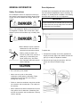
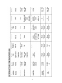
WINE COOLER
SERVICE MANUAL
5995430781 5/2005
1
SAFE SERVICING PRACTICES - ALL APPLIANCES
To avoid personal injury and/or property damage, it is important that Safe
Servicing Practices be observed. The following are some limited examples of
safe practices:
1. DO NOT attempt a product repair if you have any doubts as to your ability to
complete it in a safe and satisfactory manner.
2. Before servicing or moving an appliance:
• Remove the power cord from the electrical outlet, trip the circuit breaker to
the OFF position, or remove the fuse.
• Turn off the gas supply and allow any residual gas to dissipate for 10 to 20
minutes.
3. Never interfere with the proper operation of any safety device.
4. USE ONLY REPLACEMENT PARTS CATALOGED FOR THIS APPLIANCE.
SUBSTITUTIONS MAY DEFEAT COMPLIANCE WITH SAFETY
STANDARDS SET FOR HOME APPLIANCES.
5. GROUNDING: The standard color coding for safety ground wires is GREEN,
or GREEN with YELLOW STRIPES. Ground leads are not to be used as current
carrying conductors. It is EXTREMELY important that the service technician
reestablish all safety grounds prior to completion of service. Failure to do so
will create a hazard.
6. Prior to returning the product to service, ensure that:
• All electrical connections are correct and secure
• All electrical leads are properly dressed and secured away from sharp
edges, high-temperature components, and moving parts
• All non-insulated electrical terminals, connectors, heaters, etc. are
adequately spaced away from all metal parts and panels
• All safety grounds (both internal and external) are correctly and securely
connected
• All panels are properly and securely reassembled
ATTENTION!!!
This service manual is intended for use by persons having electrical and mechanical
training and a level of knowledge of these subjects generally considered acceptable in the
appliance repair trade. Electrolux Major Appliances cannot be responsible, nor assume
any liability, for injury or damage of any kind arising from the use of this manual.
© 2005 Electrolux Major Appliances
2
Safe Servicing Practices
Quick Reference Sheet
Owner’s Guide and Parts Information
Contact Information
General information
Safety Precautions
Door Adjustment
Specifications
Sample Wiring Diagram
Compressor/Electrical Specifications
Compressor Pins
Specifications
Refrigeration Systems
Refrigeration System Diagnosis Guide
Troubleshooting
Not Refrigerating (compressor and fan are operating)
Not Refrigerating (compressor not operating - fan operating)
Not Refrigerating (compressor and fan not operating)
Compressor Overheating
Compressor Will Not Stop Operating
Water Leak (inside unit)
Excessive Frost Build-up
Noisy
Fresh Food Temperature too Cold
3
2
4
4
4
5
5
5
7
8
9
9
9
10
11
12
12
12
12
12
12
12
13
13
13
QUICK REFERENCE SHEET
1.
www.electroluxusa.com
Owner’s guide and parts information may
be viewed or downloaded at:
2. Contact information:
Orders.
EHP Direct South:
1-800-845-4555
EHP Direct Northeast
1-800-611-4057
Fax
1-800-611-4058
EHP Direct North, Central & West 1-800-345-2566
Canada Service, Warranty, General
Questions.
Monday - Friday 8:00 AM - 5:00 EST 1-800-265-8352
U.S.A. Service, Warranty, General
Questions.
Monday - Friday 8:00 AM - 5:00 EST
1-877-4Electrolux (435-3287) Electrolux ICON brands
Damage Claims.
1-800-456-4669 (option 3, then option 2)
Parts Orders.
1-800-320-0859
Mailing Address.
Electrolux Major Appliances
P.O. Box 212378
Martinez, GA. 30917
4
GENERAL INFORMATION
Door Adjustment
All model doors are aligned at the factory before shipment. Occasional readjustment may be necessary, especially if an Overlay Panel is installed. The following
procedure will correct for up to 1/4" alignment.
Safety Precautions
Do not attempt to service or repair the unit until you
have read the entire procedure. Safety items throughout this manual are labeled with Danger, Warning or
Caution.
IMPORTANT
The door should never be flush with the top of the cabinet. Even when level, the top edge of the door will be
1/8" below the top of the cabinet
Risk of child entrapment. Before you throw away an
old refrigerator or freezer: Take off the doors, leave
shelves in place so that children may not easily climb
inside
• Never attempt to repair or perform
maintenance on the unit until the
electricity has been disconnected.
To adjust door:
• Altering, cutting of power cord,
removal of power cord, removal of
power plug, or direct wiring can
cause serious injury, fire and/or
loss of property and/or life and will
void the warranty.
1. Compare the top edge of the door (opposite the
hinges) to the top edge of the cabinet and note the
type (up or down) of adjustment needed.
2. Remove the top hinge pivot pin with a 7/64" hex
wrench and lift door off bottom hinge
pin.
CAUTION
• Do not lift unit by door handle.
• Never use an ice pick or other sharp
instrument to help speed up defrosting. These
instruments can puncture the inner lining or
damage the cooling unit.
• Failure to clean the condenser every three months
can cause the unit to malfunction. This could void
the warranty.
• Never install the unit behind closed doors. Be sure
front grille is free of obstruction. Obstructing free
air flow can cause the unit to malfunction, and may
void the warranty.
5
Be careful not to lose door closer inserts.
5. After adjustment is complete, remove the door
closers from the bottom hinge, clean thoroughly and
apply petroleum jelly to the mating surfaces of the
closers. Be sure that bosses on closers align with
holes in hinge and hinge plate. Mount door and
install top hinge pivot pin.
Note:
The hinge plate on some models do not
have the holes slotted for adjustment. New
hinge plates are available from Electrolux Parts.
3. With door upside-down, inspect the bottom hinge
plate mounting holes.
a. If your plate has slotted mounting holes, loosen
but do not remove the two hinge plate screws.
b. If your plate does not have slotted mounting
holes, remove the old plate and install the new
plate with the notch to the inside of the door.
4. If door edge opposite the hinges needs to move up,
move plate toward outside of door. If door edge
needs to move down, move plate toward inside of
door. Repeat until top edge of door is parallel with
top of cabinet and tighten screws securely.
6
Specifications
Brand
Electrolux
Electrolux
Series
Designer
Professional
Models
E24WC48EBS
E24WC48EPS
Defrost
Automatic
Automatic
Compressor
Compressor
48
48
Dimensions
Width
Height
Depth
23 15/15”
34 1/8”
23 1/4”
23 15/15”
34 1/8”
23 1/4”
Unit Wt. (lbs)
128 lbs
128 lbs
Voltage
115 VAC
115 VAC
Agency Certs
UL, cUL
UL, cUL
Adjustable
Adjustable
Handle
ICON
Professional
Badge
Electrolux ICON
Electrolux ICON
Controls
Manual
Manual
Shelves
5 side, 1 fixed display
5 side, 1 fixed display
3
3
Reversible, tinted glass
Reversible, tinted glass
always on option
always on option
Cooling Type
Total Capacity (bottles)
Legs
Temperature Zones
Door Arrangement
Lighting
7
Sample Wiring Diagram
Note: Always refer to diagram on wine cooler.
8
Compressor/Electrical Specifications:
OVERLOAD PROTECTOR
C
S
R
START RELAY
RELAY COVER
Compressor Pins:
To measure start winding resistance, measure across the C-S pins.
To measure run winding resistance, measure across the C-R pins. These pins should never measure any
resistance to ground. This would indicate a shorted compressor.
Specifications:
Start Winding Resistance: 28 OHMS.
Run Winding Resistance: 8 OHMS.
9
REFRIGERATION SYSTEMS
Normal Vapor/Compression Cycle Refrigeration
• Refrigerant is pumped from the compressor to the condenser as a high pressure, high
temperature vapor.
• As the refrigerant cools in the high pressure condenser, the vapor condenses to liquid. During
this phase change, a great amount of heat is rejected with the help of the condenser fan.
• The liquid then flows to the dryer where it is strained and filtered.
COMPRESSOR
CONDENSER
DRYER
EVAPORATOR
CAPILLARY TUBE
• From the dryer, the refrigerant flows through the capillary tube which meters the liquid refrigerant
to the evaporator. The pressure of the refrigerant is reduced to the evaporating or low side
pressure.
• The reduction of pressure on the liquid refrigerant causes it to boil or vaporize until it reaches
saturation temperature. As the low temperature refrigerant passes through the evaporator coil, it
continues to absorb a lot of heat, causing the boiling action to continue until the refrigerant is
completely vaporized. It is during this phase change that the most heat is absorbed (the cooling
takes place) in the refrigerator.
• The refrigerant vapor leaving the evaporator travels through the suction line to the compressor
inlet. The compressor takes the low pressure vapor and compresses it, increasing both pressure
and temperature. The hot high pressure gas is pumped out the discharge line and into the
condenser. The cycle continues.
10
11
Troubleshooting
Problem
DANGER
DO NOT service the unit until the main
electrical power has been disconnected.
Cause
Correction
1. Not refrigerating (compressor
and fan are operating).
Cause
a. Little or no frost pattern on
evaporator.
a. Check for sealed system leak
or restriction.
Remedy
2. Not refrigerating (compressor
not operating - fan operating).
Cause
a. Relay defective.
a. Replace relay.
b. Overload defective (open).
b. Replace overload.
c. Compressor defective.
c. Replace compressor.
Remedy
a. Replace control.
3. Not refrigerating (compressor
and fan not operating).
4. Compressor overheating.
Cause
5. Compressor will not stop
operating.
Cause
6. Water leak (inside unit).
Cause
a. Control defective (open).
b. Broken wire in compressor
circuit.
b. Repair or replace wiring.
c. Power cord not plugged in.
c. Plug in power cord.
d. Control in off position.
d. Rotate control knob clockwise.
Remedy
a. Remove restriction (clean
condenser and grille).
a. Condenser air flow restricted.
b. Condenser fan blade
obstructed.
b. Remove blade restriction.
c. Condenser fan motor stalled.
c. Replace fan motor.
d. Defective compressor.
d. Replace compressor.
Remedy
a. Adjust control warmer (counter
clockwise).
a. Control set too cold.
b. Control defective (contacts will
not open).
b. Replace control.
c. Control sensing bulb not
sensing evaporator plate.
c. Clamp bulb completely against
bottom of plate, routing bulb
away from compressor
discharge tube.
Remedy
a. Remove obstruction.
Remedy
a. Defrost drain plugged.
12
Problem
7. Excessive frost build-up.
Cause
8. Noisy.
Cause
9. Fresh food temperature too
cold.
Cause
Cause
Correction
a. Door gasket not sealing
properly.
a. Adjust door hinges or replace
door gasket.
b. Door out of alignment.
b. Align fill door hinges.
c. Water soaked cabinet
insulation.
c. Replace foamed cabinet
assembly (factoryrepair only).
d. Light stays on when door is
closed.
d. Repair light bracket.
a. Copper refrigeration tube
touching cabinet.
Remedy
a. Carefully adjust tubing.
b. Fan blade touching shroud.
b. Adjust fan mounting or shroud.
c. Fan blade obstruction (wiring,
foam insulation, packaging
material).
c. Remove obstruction.
Remedy
a. Temperature control set too
cold.
a. Adjust control to warmer setting
(counterclockwise).
13
NOTES
14
NOTES
15
16