1
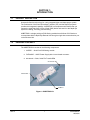
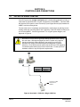
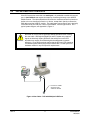
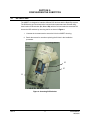
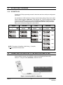
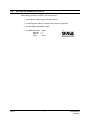
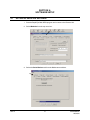
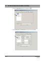
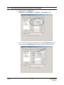
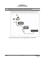
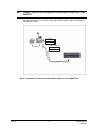
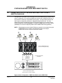
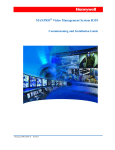
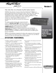
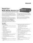
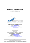
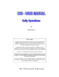
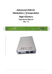
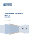
AVBPITPOS
Serial Port Point-of-Sale
Filtering Module
Installation Manual
KEMU000826 – 03/04 – Rev B
ISSUE
DATE
A
December 2003
B
March 2004
REVISIONS
Initial release. (PCN 1466)
Added protocols and reformatted document.
All rights reserved. No part of this publication may be reproduced by any means without written
permission from Honeywell Video Systems. The information in this publication is believed to be accurate
in all respects. However, Honeywell Video Systems cannot assume responsibility for any consequences
resulting from the use thereof. The information contained herein is subject to change without notice.
Revisions or new editions to this publication may be issued to incorporate such changes.
Rev. B
ii
KEMU000826
03/26/04
EXPLANATION OF GRAPHICAL SYMBOLS
The lightning flash with arrowhead symbol within an equilateral triangle is intended to
alert the user to the presence of uninsulated "dangerous voltage" within the product's
enclosure that may be of sufficient magnitude to constitute a risk of electric shock to
persons.
The exclamation point within an equilateral triangle is intended to alert the user to the
presence of important operating and maintenance (servicing) instruction in the literature
accompanying the product.
CAUTION
RISK OF ELECTRIC SHOCK
DO NOT OPEN
CAUTION: TO REDUCE THE RISK OF ELECTRIC SHOCK,
DO NOT REMOVE COVER (OR BACK).
NO USER-SERVICEABLE PARTS INSIDE.
REFER SERVICING TO QUALIFIED SERVICE PERSONNEL.
Rev. B
iii
KEMU000826
03/26/04
TABLE OF CONTENTS
SECTION 1: INTRODUCTION .................................................................................................................. 1
1.1
PRODUCT DESCRIPTION ............................................................................................................... 1
1.2
PACKAGE CONTENTS .................................................................................................................... 1
SECTION 2: CONTROLS AND CONNECTIONS...................................................................................... 2
2.1
POS WITH A SINGLE COM PORT ................................................................................................... 2
2.2
POS WITH MULTIPLE COM PORTS................................................................................................ 3
SECTION 3: CONFIGURING THE AVBPITPOS ....................................................................................... 4
3.1
3.2
DIP SWITCHES ................................................................................................................................ 4
3.1.1
DIP SWITCH S1 .............................................................................................................. 5
3.1.2
DIP SWITCH S2 .............................................................................................................. 5
3.1.3
DIP SWITCH S3 .............................................................................................................. 6
CONNECTING THE AVBPITPOS TO THE RAPID EYE REMOTE UNIT........................................... 6
3.3
SETTING UP GILBARCO G-SITE®.................................................................................................. 7
SECTION 4: SOFTWARE SETUP ............................................................................................................. 8
4.1
SETTING UP RAPID EYE SOFTWARE............................................................................................. 8
SECTION 5: TROUBLESHOOTING ........................................................................................................ 15
5.1
DIAGNOSTIC MODE...................................................................................................................... 15
5.2
INDICATORS.................................................................................................................................. 15
APPENDIX A: SYSTEM DIAGRAMS....................................................................................................... 16
A.1
CONNECTING A POS SYSTEM WITH A SINGLE COM PORT...................................................... 16
A.2
CONNECTING A POS SYSTEM WITH A SEPARATE COM PORT FOR PRINTER........................ 17
APPENDIX B: SYSTEM DIAGRAM USING B&B SMART SWITCH ....................................................... 18
B.1
CONNECTING A POS SYSTEM USING B&B SMART SWITCH AND 4 AVBPITPOS MODULES.. 18
FIGURES
Figure 1: AVBPITPOS Kit .............................................................................................................................. 1
Figure 2: New Cable – POS with a Single COM Port.................................................................................... 2
Figure 3: New Cable – POS with Multiple COM Ports .................................................................................. 3
Figure 4: Accessing DIP Switches ................................................................................................................ 4
Figure 5: Connecting AVBPIT1 to Rapid Eye ............................................................................................... 6
Figure 6: Connecting a POS device with a single COM port to the AVBPITPOS....................................... 16
Figure 7: Connecting a POS device with multiple COM ports to the AVBPITPOS..................................... 17
Figure 8: Basic Configuration – B&B Smart Switch and 4 AVBPITPOS ..................................................... 18
Rev. B
iv
KEMU000826
03/26/04
SECTION 1:
INTRODUCTION
1.1
PRODUCT DESCRIPTION
Honeywell offers the technology for a truly integrated video and data capture system.
The combination of the Protocol Interface Translator (PIT) and the Rapid Eye system
provides this integrated capability. AVBPITPOS is a transparent serial device that can
capture the serial data from a Point-of-Sale (POS) device and send it to the Rapid Eye
system for viewing, recording, and searching.
AVBPITPOS is a single serial port POS filtering module that will allow a POS device to
communicate with the Rapid Eye Remote Unit through a single data communication port
on the Remote Unit.
1.2
PACKAGE CONTENTS
The AVBPITPOS kit consists of the following components:
1. AVBPIT1 – Serial Port POS filtering module
2. DKT507ND – 12VDC Power Supply with 2.1mm female connector
3. 921400-05 – Cable, Serial File Transfer DB9
921400-05
DKT507ND
AVBPIT1
Figure 1: AVBPITPOS Kit
Rev. B
1
KEMU000826
03/26/04
SECTION 2:
CONTROLS AND CONNECTIONS
2.1
POS WITH A SINGLE COM PORT
If the POS system has a single serial port and it is already being utilized for printing, a
cable must be manufactured to connect a POS device to the AVBPIT1. This new cable
will allow the POS system to share Transmit (TX) and Signal Ground (SG) between the
AVBPIT1 and the existing printer.
The new cable can be completely remanufactured or made simply by splicing into the
existing cable and connecting Pins 2 and 5 (typically) of the POS serial port with pins 3
and 5 of the AVBPIT1. See the Figure below. For a typical system diagram, see
Appendix A, Figure 6.
Be careful to comply with all applicable RS232 standards when creating
this new cable. Although the Rapid Eye and PIT system only require 2
signals to effectively capture POS data, the serial ports on the POS
terminals may require other RS232 signals be addressed to operate
effectively. Some POS terminals require that the RTS and CTS signals be
connected together before the port will transmit data. Consult your POS
hardware manual for any POS-specific requirements.
POS-DB9
AVBPITPOS-DB9
(TX) Pin 2
(RX) Pin 3
(SG) Pin 5
(SG) Pin 5
Connect to COM0
Channel of the
AVBPIT1
Figure 2: New Cable – POS with a Single COM Port
Rev. B
2
KEMU000826
03/26/04
2.2
POS WITH MULTIPLE COM PORTS
If the POS system has more than one serial port, it is preferable to enable this second
port in Journal Mode and capture its output by connecting it directly to the AVBPIT1
COM0 Channel. The cable utilized here must also be manufactured and is pinned out
similar to the one described in Section 2.1 above, except that it directly connects the
POS device and the AVBPIT1 module. The cable must connect Pins 2 and 5 (typically)
of the POS serial port with pins 3 and 5 of the AVBPIT. See the figure below. For a
typical system diagram, see Appendix A, Figure 7.
Be careful to comply with all applicable RS232 standards when creating
this new cable. Although the Rapid Eye and PIT system only require 2
signals to effectively capture POS data, the serial ports on the POS
terminals may require other RS232 signals be addressed to operate
effectively. Some POS terminals require that the RTS and CTS signals be
connected together before the port will transmit data. Consult your POS
hardware manual for any POS-specific requirements.
Connect to COM0
Channel of the
AVBPIT1 Module
Figure 3: New Cable – POS with Multiple COM Ports
Rev. B
3
KEMU000826
03/26/04
SECTION 3:
CONFIGURING THE AVBPITPOS
3.1
DIP SWITCHES
The AVBPIT1 is designed to interface different POS devices with the Rapid Eye system.
The POS device and its related serial communication parameters are selected using
three banks of DIP switches (S1, S2 and S3), which are found under the removable lid.
Access the DIP switches by removing the lid as shown in Figure 4.
1. Unscrew the 2 screws used to secure the lid to the AVBPIT1 housing.
2. Retain the screws for use when replacing the lid later in the installation
procedure.
S2
S3
S1
Figure 4: Accessing DIP Switches
Rev. B
4
KEMU000826
03/26/04
3.1
DIP SWITCHES, CONTINUED
3.1.1
DIP SWITCH S1
Use the S1 bank of DIP switches to select different operational modes for the AVBPIT1.
Note:
The dark area represents the desired setting of each individual switch within the
DIP switch.
ON
ON
Radiant Mode
S1
1 2 3 4 5 6 7 8
1 2 3 4 5 6 7 8
ON
ON
Retalix Mode
S1
1 2 3 4 5 6 7 8
ON
ON
Javelin Mode
1 2 3 4 5 6 7 8
1 2 3 4 5 6 7 8
ON
Sharp Mode
S1
1 2 3 4 5 6 7 8
ON
S1
1 2 3 4 5 6 7 8
ON
S1
1 2 3 4 5 6 7 8
ON
S1
1 2 3 4 5 6 7 8
ON
S1
1 2 3 4 5 6 7 8
Hex Mode
S1
ON
S1
Wayne Mode
S1
1 2 3 4 5 6 7 8
S1
Verifone Mode
S1
1 2 3 4 5 6 7 8
PAR ¾ Generic
Mode
NCR 7454-3201M403 Mode
Radiant M100
Mode
Panasonic 5500
Mode
ON
NCR 7454 Mode
S1
1 2 3 4 5 6 7 8
ON
S1
1 2 3 4 5 6 7 8
ON
S1
1 2 3 4 5 6 7 8
NCR Model 1000
Mode
Gilbarco G-SITE®
Mode
Diagnostic Mode
(All Switches OFF)
Diagnostic Mode can also be used to pass unfiltered or generic ASCII data to the
Rapid Eye system.
3.1.2
DIP SWITCH S2
The S2 bank of DIP switches are preset and all should remain in
the OFF position.
ON
S2
1 2 3 4 5 6 7 8
Rev. B
5
KEMU000826
03/26/04
3.1
DIP SWITCHES, CONTINUED
3.1.3
DIP SWITCH S3
Consult your POS programming manual for baud rate and other serial port configuration
parameters
Use the S3 bank of DIP switches to change communication settings if they need to differ
from the default settings of 9600, 8, N, 1 (All Switches off). This will configure the COM0
Channel of the AVBPIT1 module to match the printer or journal port settings required
by the POS device. RS232 parameters such as Stop Bits, Data Bits, Parity, and Baud
Rate can be individually configured as shown below.
Stop Bit
Switch
1
Data Bits
Switches
2 and 3
Stop
Bits
ON
Parity
Switches
4 and 5
Data
Bits
S3
8
S3
1 2 3 4 5 6 7 8
2
S3
1 2 3 4 5 6 7 8
1 2 3 4 5 6 7 8
ON
7
S3
ON
Even
S3
1 2 3 4 5 6 7 8
9600
S3
1 2 3 4 5 6 7 8
1 2 3 4 5 6 7 8
ON
ON
Odd
S3
19200
S3
1 2 3 4 5 6 7 8
ON
Baud
Rate
ON
None
S3
1 2 3 4 5 6 7 8
ON
Switches
6, 7, and 8
Parity
ON
ON
1
Baud Rate
2400
S3
1 2 3 4 5 6 7 8
1 2 3 4 5 6 7 8
ON
4800
S3
1 2 3 4 5 6 7 8
NOTE: The setting 7 (Data Bits), N (No Parity), 1 (Stop Bit)
is not supported for all baud rates.
ON
1200
S3
1 2 3 4 5 6 7 8
3.2
CONNECTING THE AVBPITPOS TO THE RAPID EYE REMOTE UNIT
Connect COM1 Channel of the AVBPIT1 module to the Rapid Eye Remote Unit,
COM port 1 using the cable (921400-05) included in the kit.
Figure 5: Connecting AVBPIT1 to Rapid Eye
Rev. B
6
KEMU000826
03/26/04
3.3
SETTING UP GILBARCO G-SITE®
When setting up Gilbarco G-SITE®, follow these steps:
1. Leave S1 in the Debug mode (all switches OFF).
2. Set the Register output to a Citizen Printer (Printer not required.)
3. Set the Register Baud Rate to 9600.
4. Set S3 to Baud Rate
Data Bits
Stop Bit
Parity
Rev. B
=
=
=
=
9600
7
1
Even
7
ON
S3
1 2 3 4 5 6 7 8
KEMU000826
03/26/04
SECTION 4:
SOFTWARE SETUP
4.1
SETTING UP RAPID EYE SOFTWARE
1. Start the Rapid Eye Multi VIEW program and connect to the Remote Unit.
2. Select Maintain from the top menu bar.
3. Select the Serial Devices tab from the Maintenance window.
Rev. B
8
KEMU000826
03/26/04
4.1
SETTING UP RAPID EYE SOFTWARE, CONTINUED
4. Expand the New Devices section by clicking on the
.
5. Select Data Input from New Devices and Drag and Drop onto Port 1.
Rev. B
9
KEMU000826
03/26/04
4.1
SETTING UP RAPID EYE SOFTWARE, CONTINUED
6. Configure Port 1 – Data Input at:
Baud Rate = 9600; Data Bits = 8; Stop Bits =1, Parity Bits = None
7. You can further customize the configuration by giving the Data Input a unique
name, click in the Device Name field and enter a name for the POS device.
Rev. B
10
KEMU000826
03/26/04
4.1
SETTING UP RAPID EYE SOFTWARE, CONTINUED
8. Once the device is configured, select Apply.
9. Select Yes in response to the Maintenance Message and wait for the System
Operational message to appear in the Feedback dialogue box.
Rev. B
11
KEMU000826
03/26/04
4.1
SETTING UP RAPID EYE SOFTWARE, CONTINUED
10. After System Operational feedback is received, test the communication
between the AVBPITPOS and Rapid Eye by toggling DIP switch (S1) position 8
ON and OFF. Data window should display similar result as shown in the
Panasonic window below.
11. You can further customize the configuration by setting up the Rules to create
Log and Alarm events based on the data being captured by the Rapid Eye
system. If Rules are not required, skip to Step 14.
12. Create rules for data events by entering the appropriate information in the Event
Name and Event Rule dialogue boxes then clicking the Add button. The Event
Name will appear in the Events window. Consult Rapid Eye’s VIEW user Guide
for more information about this capability.
Rev. B
12
KEMU000826
03/26/04
4.1
SETTING UP RAPID EYE SOFTWARE, CONTINUED
13. Once the rules are configured, select Apply then Yes in response to the
Maintenance Message. Wait for the System Operational message to appear
in the Feedback dialogue box. (Same procedure as described in steps 8 - 9).
14. From VIEW, initiate a Live session to the Remote Unit and verify that installation
and setup are correct and that a separate data window is available for the POS
device. Initiate a Live session to the Remote Unit. A data stream will appear and
can be selected in the same manner as any other available video stream. All
streams will be selected by default; this will be the same for Live or Retrieval
sessions. Verify that the POS device is communicating with the Rapid Eye
system by initiating a transaction at the POS device and verifying that the correct
data appears in the Data Input window.
Rev. B
13
KEMU000826
03/26/04
4.1
SETTING UP RAPID EYE SOFTWARE, CONTINUED
15. Once installation and setup are complete and verified, replace and secure the lid
to the AVBPIT1 module using the screws removed in Section 3.1. The
AVBPITPOS installation is now complete.
Rev. B
14
KEMU000826
03/26/04
SECTION 5:
TROUBLESHOOTING
5.1
DIAGNOSTIC MODE
Enter the Diagnostic Mode by setting all S1 DIP
switches to the OFF position and cycling the power of
the AVBPIT1 module
ON
S1
1
2
3
4
5
6
7
8
Diagnostic
Mode
Rapid Eye will display a message in the Data Input window similar to that shown below.
Diagnostic Mode can also be used to pass unfiltered or generic ASCII data to the Rapid
Eye system.
5.2
Rev. B
INDICATORS
Green LED on the COM0
Channel flashes
Data is being transmitted by the POS device and being
received at the AVBPIT1 COM0 Channel.
Yellow LED on the COM1
Channel flashes
Data is being transmitted to the Rapid Eye.
Printer won’t print when
PIT is connected
For single COM port POS installations check if there is
signal on Pin 3 of the cable connected to printer. Pin 3 is
the transmit data pin and a signal here will halt printing.
15
KEMU000826
03/26/04
APPENDIX A:
SYSTEM DIAGRAMS
A.1
CONNECTING A POS SYSTEM WITH A SINGLE COM PORT
See the figure below for a typical system diagram when connecting a POS device with a
single COM port which will be shared between the printer and the AVBPIT1 module.
POS-DB9
(TX) Pin 2
(SG) Pin 5
AVBPITPOS-DB9
(RX) Pin 3
(SG) Pin 5
921400-05
Figure 6: Connecting a POS device with a single COM port to the AVBPITPOS
Rev. B
16
KEMU000826
03/26/04
A.2
CONNECTING A POS SYSTEM WITH A SEPARATE COM PORT FOR
PRINTER
See the figure below for connecting a POS device with multiple COM ports enabled to
the AVBPIT1 module.
POS-DB9
(TX) Pin 2
(SG) Pin 5
AVBPITPOS-DB9
(RX) Pin 3
(SG) Pin 5
921400-05
Figure 7: Connecting a POS device with multiple COM ports to the AVBPITPOS
Rev. B
17
KEMU000826
03/26/04
APPENDIX B:
SYSTEM DIAGRAM USING B&B SMART SWITCH
B.1
CONNECTING A POS SYSTEM USING B&B SMART SWITCH AND 4
AVBPITPOS MODULES
This appendix is provided to document early uses of the AVBPITPOS in a multiple POS
device configuration. By combining a B&B Smart Switch and 4 AVBPITPOS devices, it
was possible to develop a multiple POS device system. The figure below depicts this
basic system configuration attached to a Rapid Eye Multi Remote Unit. For more
detailed information regarding this type of POS implementation visit our web site and
download Application Note AVAN000851 (Configuring a B&B Electronics Smart Switch
(232BSS4) for use with the Rapid Eye Multi and the AVBPITPOS Filtering Module).
NOTE: When deploying a new multiple POS device systems we recommend using the
AVBPIT4POS device instead of the B&B Smart Switch and multiple
AVBPITPOS devices, consult the web site for details.
Cash Register
Cash Register
Cash Register
Cash Register
Up to (4) AVBPITPOS units
(to filter Cash Register Data)
Port A Port B Port C Port D
(1) 4-port Smart Switch
(232BSS4)
232BSS4
MASTER PORT
A UD IO I N
[1]
[2 ]
IN
IN
IN
IN
IN
IN
IN
V IDE O
S PO T O U T
IN
A U D IO OUT
[1]
1
[2 ]
RS -2 3 2 [1]
OU T
2
OUT
3
OU T
4
OU T
5
OU T
6
OU T
7
OU T
1
8
OUT
VIDEO INPUTS
R S -2 3 2 [2]
IN
IN
9
TE L C O
OU T
IN
10
OUT
IN
11
OU T
OU T
IN
IN
12
13
OU T
IN
14
OU T
V IDE O
M UX O UT
IN
15
OU T
O
U
T
P
U
T
S
16
OUT
ALARM / CONTROL INPUTS
1 0 / 10 0 B T
C
O
N
T
R
O
L
G
2
G
3
G
4
G
5
G
6
G
7
G
8
G
1 G 2G 3 G 4G 5 G 6 G7 G8 G
9
G
10 G
11 G
12 G 1 3 G
14
G
15
G 16
G
Ademco Video Rapideye Multi
(running version 4.1(3.5) or greater)
Figure 8: Basic Configuration – B&B Smart Switch and 4 AVBPITPOS
Rev. B
18
KEMU000826
03/26/04
Video Systems
www.honeywellvideo.com
1-800-796-CCTV
© 2004 Honeywell International Inc.