1
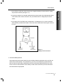
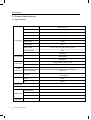
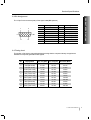
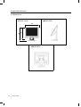
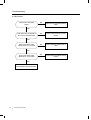
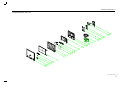
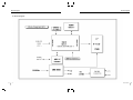
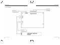
Service Manual
Model : Belinea 101725
Art. No. 111707
MAXDATA Systeme GmbH
Elbestr. 12-16
45768 Marl / Germany
Contents
1. Precautions
Safety Precautions
Servicing Precautions
Electrostatically Sensitive Devices (ESD) Precautions
4
6
7
2. Product Specifications
Specifications
Dimensions
Pin Assignment Table D-Sub 15 Pin Connector
Timing Chart
8
9
10
10
3. Disassembly and Reassembly
11
4. Troubleshooting
No Power
No Video
No Picture
No Sound
14
15
16
16
5. Exploded View & Parts List
17
6. Packing & Unpacking
19
7. Electrical Parts List
Main Board
OSD Key Board
Others
2
Service Manual
20
22
22
Contents
8. Block Diagram
CONTENTS
25
9. Wiring diagram
27
10. PCB Layout
Main PCB
Key PCB
Semiconductor Aead Identification
28
31
31
11. Schematic Diagram
32
Copyright
2003 by Maxdata Systeme GmbH
All rights reserved.
This manual may not, in whole or in part, be copied,
photocopied, reproduced, translated, or converted to any
electronic or machine readable form without prior written
permission of Maxdata Systeme GmbH.
Belinea 101725 Service Manual
First edition April 2003
111707 Service Manual
3
Precautions
1. Precautions
Follow these safety, servicing and ESD precautions to prevent damage and to protect against
potential hazards such as electrical shock.
1-1 Safety Precautions
1-1-1 Warnings
1. For continued safety, do not attempt to modify the circuit board.
2. Disconnect the AC power Jack before servicing.
1-1-2 Servicing the LCD Monitor
1. When servicing the LCD Monitor Disconnect the AC line cord from the AC outlet.
2. It is essential that service technicians have an accurate voltage meter available at all times.
Check the calibration of this meter periodically.
1-1-3 Fire and Shock Hazard
Before returning the monitor to the user,perform the following safety checks :
1. Inspect each lead dress to make certain that the leads are not pinched or that hardware is not
lodged between the chassis and other metal parts in the monitor.
2. Inspect all protective devices such as nonmetallic control knobs, insulating materials, cabinet
backs, adjustment and compartment covers or shields, isolation resistor-capacitor networks,
mechanical insulators, etc.
3. To be sure that no shock hazard exists, check for leakage current in the following manner.
Warning : Do not use an isolation transformer during this test.
a. Plug the AC line cord directly into a 120 Volt AC outlet.
b. Unisg two clip leads, connect 1.5 , 10 watt resistor paralleled by a 0.15 capacitor in series
with an exposed metal cabinet part and a known earth ground, such as an electrical conduit or
electrical ground connected to an earth ground.
4
111707 Service Manual
Precautions
PRECAUTION
c. Use a SSVM or VOM with 1000 ohms per-volt or higher sensitivity to measure the AC voltage
drop across the resistor (see Figure 1-1).
d. Connect the resistor to an exposed metal part having a return path to the chassis(metal cabinet,
screw heads, knobs, shafts, escutcheon, etc.) and measure the AC voltage drop across the
resistor.
e. Any reading of 5.25 Volt RMS ( this corresponds to 3.5 milliampere AC ) or more is excessive
and indicates a potential shock hazard. Correct the shock hazard before returning the monitor to
the user.
AC Voltmter
1500
Test Probe
0.15
To Exposed
Metal Parts
To Known
Earth Ground
Figure 1-1.
Leakage Current Test Circut
1-1-4 Product Safety Notices
Some electrical and mechanical parts have special safety-related characteristics which are often not
evident from visual inspection. The protection they give may not be obtained by replacement that
does not have the same safety characteristics as the recommended replacement part may create
shock, fire and /or other hazards. Product safety is under review continuously and new instructions
are issued whenever appropriate.
111707 Service Manual
5
Precautions
1-2 Servicing Precautions
WARNING : An electrolytic capacitor installed with the wrong polarity might explode.
Caution
: Before servicing instruments covered by this service manual and its supplements,
read and follow the Safety Precautions section of this manual.
Note
: If unforeseen circumstances create conflict between the following servicing preautions
and any of the safety precautions, always follow the safety precautions.
1-2-1. General Servicing Precautions
1. Servicing precautions are printed on the cabinet, and should be followed closely.
2. Always unplug the unit's AC power cord from the AC power source before attempting to :
(a) remove or reinstall any component or assembly, (b) disconnect PCB plugs or connectors,
(c) connect a test component in paralled with an electrolytic capacitor.
3. Some components are raised above the printed circuit board for safety. An insulation tube or tape
is sometimes used. The internal wiring is sometimes clamped to prevent contact with thermally hot
components. Reinstall all such elements to their original position.
4. After servicing, always check that the screws, components and wiring have been correctly
reinstalled. Make sure that the portion around the serviced part has not been damaged.
5. Check the insulation between the blades of the AC plug and accessible conductive parts
(examples; metal panels, input terminals and earphone jacks)
6. Insulation Checking Procedure : Disconnect the power cord from the AC source and turn the power
switch ON. Connect an insulation resistance meter(500V) to the blades of the AC plug.
The insulation resistance between each blade of the AC plug and accessible conductive parts
(see above) should be greater than 1 megohm.
7. Always connect a test instrument's ground lead to the instrument chassis ground before connecting
the positive lead; always remove the instrument's ground lead last.
6
111707 Service Manual
Precautions
1-3 Electrostatically Sensitive Devices(ESD) Precautions
PRECAUTIONS
Some semiconductor (solid state) devices can be easily damaged by static electricity. such
components are commonly called Electrostatically Sensitive Devices(ESD). Examples of typical ESD
devices are integrated circuits and some field-effect transistors. The following techniques will reduce
the incidence of component damage caused by static electricity.
1. Immediately before handling any semiconductor components or assemblies, drain the electrostatic
charge from your body by touching a known earth ground. Alternatively, wear a discharging
wrist strap device. To avoid a shock hazard, be sure to remove the wrist strap before applying
power to the monitor.
2. After removing an ESD-equipped assembly, place it on a conductive surface such as aluminum foil
to prevent accumulation of an electrostatic charge.
3. Do not use freon-propelled chemicals. These can generate electrical charges Sufficient to damage
ESDs.
4. Use only a ground-tip soldering iron to solder ESDs.
5. Use only an anti-static solder removal device. Some solder removal devices not classified as "antistatic" can generate electrical charges sufficient to damage ESDs.
6. Do not remove a replacement ESD from its protective package until you are ready to install it. Most
relacement ESDs are packaged with leads that are electrically shorted together by conductive
foam, aluminum foid or other conductive materials.
7. Immediately before removing the protective material from the leads of a replacement ESD, touch
the protective material to the chassis or circuit assembly into which the device will be installed.
Caution : Be sure no power is applied to the chassis or circuit and observe all other safety
precautions.
8. Minimize body motions when handling unpackaged replacement ESDs. Motions such as brushing
clothes together, or lifting your font from a carpeted floor can generate enough static electricity to
damage an ESD.
111707 Service Manual
7
Precautions
2. Product Specifications
2-1 Specifications
Model
Belinea 101725
Type
Amorphous Active Matrix Super TFT LCD
Screen Size
LCD PANEL
Maximum Resolution
1280 X 1024 @ 75Hz
Pixel Range
0.264mm X 0.264mm
Display Colors
16.2M
Contrast Rate
350 : 1
Viewing Angle
70° / 70° / 60° / 60° ( left / right / up / down )
Response Speed
Brightness
Synchornization Horizontal Frequency
Vertical Frequency
Video Signal
Video Input
Synchronous Signal Mode
Maximum
Power
Consumption Power Saving Mode
Control Keys
Audio Output
Front part
Normal
Max
25ms
250 cd/m2
79.9KHz( Max )
75HZ( Max )
Analog RGB (0.714Vpp) 75 ohm
H,V separate TTL Sync,SOG,COMPOSITE
48W
Under 1W
MUTE,MENU,SELECT/AUTO,POWER,
- , + , VOL SWITCH
1W/Ch
1.5W/Ch
Combo board
90~240Vac(50~60Hz),0.65A
Wall Mount
VESA Standard
Safety Standard
Safety & EMI
EMI
Low Radiation
Dimension
8
43.2cm ( Diagonal )
Size and Weight
111707 Service Manual
CB,TUV
CE
TCO' 99
380 X 176 X 368 / 5.8Kg
Product Specifications
2-2 Pin Assignment
PRODUCT SPECIFICATIONS
The 15-pin D-sub connector(male) of the signal cable(IBM systems)
5
1
10
6
11
15
Pin No
Assignment
Pin No
Assignment
1
2
Red Video
Green Video
9
10
5V Input
Ground
3
Blue Video
11
Ground
4
5
N.C
Ground
12
13
SDA (DDC Data)
H-Sync
6
7
Red Video Ground
Green Video Ground
14
15
V-Sync
SCL (DDC Clock)
8
Blue Video Ground
2-3 Timing chart
This section of the service manual describes the timing that the computer industry recognizes as
standard for computer-generated video signals.
No.
1
2
Display Mode
VGA (720 X 400)
VGA (640 X 480)
Hor. Freq (kHz)
31.469
31.469
Ver. Freq (Hz)
70.087
59.940
Dot Clock (MHz)
28.322
25.175
3
4
5
6
7
8
9
10
11
12
VGA (640 X 480)
SVGA (800 X 600)
SVGA (800 X 600)
XGA (1024 X 768)
XGA (1024 X 768)
SXGA (1280 X 1024)
SXGA (1280 X 1024)
MAC (640 X 480)
MAC (832 X 624)
MAC (1152 X 870)
37.500
37.900
46.875
48.363
60.023
63.981
79.976
35.000
49.726
68.681
75.000
60.320
75.000
60.004
75.029
60.020
75.025
66.667
74.551
75.062
31.500
40.000
49.500
65.000
78.750
108.000
135.000
30.240
57.284
100.000
111707 Service Manual
9
Product Specifications
2-4 Dimensions
FRONT VIEW
SIDE VIEW
176
368
380
REAR VIEW
10
Service Manual
Disassembly and Reassembly
DISASSEMBLY AND REASSEMBLY
3. Disassembly and Reassembly
The section of the service manual describes the disassembly and reassembly procedure for
the Belinea 101725 Monitor.
WARNING : This has to be disassembled and reassembled carefully because TFT-LCD Panel
is weak for impact. This monitor contains electrostatically sensitive devices.
Use caution when handling these components.
3-1 Disassembly
Cautions : 1. Disconnected the monitor from the power source before disassembly.
2. Follow these directions carefully; never use metal instruments to pry apart the cabinet.
3-1-1 Separation between display part and stand part
1. Diconnect Power Cord and Signal Cable.
2. Remove the 4 screws on the stand.
3. Pry it off the back stand of the monitor.
3-1-2 The Display part Disassembly
The Rear housing Removal
1. Remove the 2 screws on the rear corner of the Rear Cover.
2. Remove Rear Cover from the Front Cover.
3. Remove 2 screws on the Rear Shield Cover and remove it.
4. Disconnect Combo harness and LVDS harness.
5. Remove 4 screws on the Main PCB.
6. Remove 1 screws on the F.G cable of Combo Board.
7. Remove 4 screws on the Combo Board Assembly and then remove it.
8. Remove I/O Shield.
9. Disconnect Key harness on the Main Board.
10. Remove the LVDS harness on the Panel.
11. Remove 2 screws on the Main chassis.
12. Remove Front Cover.
13. Remove 4 screws on the Side of Panel.
14. Remove the Main chassis.
111707 Service Manual
11
Disassembly and Reassembly
Figure
12
111707 Service Manual
Disassembly and Reassembly
DISASSEMBLY AND REASSEMBLY
3-2 Reassembly
3-2-1 Display part Reassembly
As you reassemble reversely the display part dissambly method, confirm that insulation plate puts into
on the left of the TFT-LCD panel and main chassis.
3-2-2 Display part and Stand part Reassembly
Reassembly reversely the Multimedia Stand part disassembly method.
111707 Service Manual
13
Troubleshooting
4. Troubleshooting
4-1 No Power
Does proper DC 5V appear at
pin2, pin3 of CN1
NO
Check Combo board and
combo harness
NO
Check U6 and
related circuit of U7
NO
Check U2 and
related circuit of U2
NO
Check X200 and
related circuit of X200
NO
Check U201 and
related circuit of U201
NO
Check U202 and
related circuit of U202
YES
Does proper DC 3.3V appear at
pin 4 of U1
YES
Does proper DC 2.5V appear at
Pin 4 of U2
YES
Does proper 14.318MHz appear
at Pin 102.103 of X200
YES
Does proper signal ouput
appear at pin 139~142,145~156
of U201
YES
Does proper signal ouput
appear at pin 13~21 of U202
YES
Replace Main Board
14
111707 Service Manual
Troubleshooting
4-2 No Video
brinking
It indicates the monitor is in power
saving mode
NO
Check U600 and related circuit
of U600
NO
Check CN100 and related circuit
of CN100
NO
Check U201 and related circuit
of CN100
TROUBLESHOOTING
Check the Power indicating LED
Green
Does proper DC 5V appear at
pin 2,3 of U600
YES
Does proper signal appeear at
Pin 127,131,135,100,101 of
U201
YES
Does proper signal output
appear at pin48~57,64~73 of
U201
YES
Replace Panel
111707 Service Manual
15
Troubleshooting
4-3 No Sound
Check Phone Jack(J400)
Signal.
NO
Check Phone Jack(J400)& Stereo
Cable.
NO
Check Combo board and combo
harness
NO
Check U400 and related circuit of
U400
NO
Check CN401 and related circuit of
CN401
YES
Dose proper DC 12V appear at
pin 15,16 of U400(TDA7496)
YES
Dose proper signal output
appear at pin 14, 17 of U400
YES
Dose proper signal output
appear at pin 1,3 of CN401
YES
Check Speaker Wire and Speaker
16
111707 Service Manual
Exploded View & Parts List
7. Exploded View & Parts List
16-E
16-D
16-C
16-B
16-A
15-D
15-C
15-B
15-A
14
13
H
1
12
JST
2
H
1
JST
2
11
10
9
8
7
6
5
4
1-C
1-B
3
2
1-A
111707 Service Manual
17
Exploded View & Parts List
NO.
1
PART NAME
CODE NO.
DESCRIPTION
Q’TY
BEZEL FRONT ASS'Y
6526170009AD
-
1
1-A
BEZEL FRONT
6226170014AD
H750,OEM,MAXDATA,
1
1-B
LENS,POWER
6226170020AD
H750/H550,OEM,PMMA
1
1-C
KNOB CONTROL
6226170030AD
H750,OEM,MAXDATA,
1
2
SPEAKER
56410003AAAD
NB-04301-15,1
3
T/T,SCREW
67613004AAAD
BHB,+,3 8,.,."
4
4
17""TFT-LCD PANEL
5417L00814AD
LTM170EU-L01,LVDS,8BIT,16.2M,
1
5
MACHINE,SCREW
68660001AAAD
BH,M3 6
6
MAIN,CHASSIS,ASS'Y
6526170004AD
H750,SECC,1.0T,AMLCD,HYDIS
1
7
ASS'Y, COMBO B'D
3322330002VD
17"",SMPS-12V/5V,48W,
1
SILVER(B2050),ABS-HB,SD-0150,C7425
SILVER(B2050),ABS-HB,SD-0150,C7425
X1
INCH,8 OHM,
2
350HZ,1.0W
SXGA(1280*1024),4CCFL,75HZ
4
INVERTER-6.5MARMS,IPT/BENTEK
8
T/T,SCREW
67613007AAAD
BH,B-TYPE,+,M3X6
8
9
ASS'Y, PCB MAIN,DIP
0526171002AA
TFT,B17CF(H750_AMLCD),PCB MAIN,DIP
1
10
IO,SHIELD
6326170005AD
SPTE,0.5T
1
11
SHIELD,COVER
6326170003AD
SECC,1.0T
1
12
T/T,SCREW
67613007AAAD
BH,B-TYPE,+,M3X6
2
13
HOUSING,REAR
6226170002AD
ABS-HB,SD-0150,K2440
1
14
T/T,SCREW
67613012AAAD
BHB,+,M4X 10,BLACK
2
15
STAND,BASE,ASS'Y
0926170001AD
-
1
15-A
RUBBER,FOOT
6222990001AD
NR,15.2 ,1.3T,GRAY(423C)
3
15-B
T/T SCREW
67213001AAAD
FHB,+,3 8
5
15-C
BOTTOM,PLATE
6326170007AD
SECC,2.0T
1
15-D
STAND,BASE
6226170010AD
ABS-HB,SD-0150,K2440,
1
16
STAND,NECK,ASS'Y
0926170002AD
-
1
16-A
STAND,FRONT
6226170004AD
ABS-HB,SD-0150,K2440
1
16-B
BODY,FRAME
6326170006AD
SECC,2.0T
1
16-C
T/T,SCREW
67613012AAAD
BHB,+,M4X 10,BLACK
5
SILVER_SPRAY(S33-740-A8912)
18
16-D
HINGE,ASS'Y
6526170002AD
ABS-HB,SD-0150,K2440
1
16-E
STAND,BACK
6226170005AD
ABS-HB,SD-0150,K2440
1
111707 Service Manual
REMARKS
Packing & Unpacking
6. Packing & Unpacking
PACKING & UNPACKING
No
Description
Specification
Quantity
Remarks
1
Tape-Masking
OPP W75 CLR
1.2 Mt
-
2
Carton Box
Belinea 101725
1EA
CB DW-3
3
Set-Monitor
Belinea 101725
1Set
EPS 60M C=0.018
4
Cushion-L/R
Belinea 101725
1Set
17" TFT Monitor
5
Gift Box
Belinea 101725
1EA
Cable Etc.
111707 Service Manual
19
Electrical Parts List
Introduction
7. Electrical Parts List
7-1. MAIN BOARD
LOCATION No.
PART NO.
TYPE
DESCRIPTION
CE1,CE2,CE5,CE6,CE205,CE600
276604763CHD
CAP, CAN-ELECT,G.P
47UF, 16V, 20%, CASE:6.3X5, -40 ~ +85
CE3,CE4
276601073CHD
CAP, CAN-ELECT, G.P
100UF, 16V, 20%, CASE:6.3X6, -40 ~ +85 ,SMD
CE7,CE200,CE201,CE202,CE203,CE204
276602263CHD
CAP, CAN-ELECT,G.P
22UF, 16V, 20%, CASE:5X5, 5M, -40 ~ +85 ,SMD
26508R0015MD
CAP, CERAMIC
0.1UF, 50V, +80%/-20%, Y5V, SMD, 1608
,SMD
C1,C2,C3,C4,C5,C6,C7,C100,C200,C201,
C202,C203,C204,C205,C206,C207,C209,
C210,C211,C212,C213,C214,C216,C217,
C218,C219,C220,C221,C222,C223,C224,
C225,C226,C229,C230,C232,C233,C400,
C403,C602
C101,C102,C103,C104,C105,C106
265001038APJ
CAP,CERAMIC
0.01UF, 50V, 10%, X7R, SMD, 1608
C208,C215,C231
26508902219D
CAP, CERAMIC
220PF, 50V, 5%, COG, SMD, 1608
C604,C605
26508900509D
CAP, CERAMIC
5PF, 50V, 5%, COG, SMD, 1608
C603
265001028APJ
CAP CERAMIC
1000PF, 50V, 10%, X7R, SMD, 1608
R100,R110,R210,R211,R212,R217,R218,
21701037AT
RES,CHIP,CT
10K OHM, 5%, 1/16W, 1608
R3
21701027AT
RES,CHIP,CT
1K OHM, 5%, 1/16W, 1608
R4,R5
21704717AT
RES,CHIP,CT
470 OHM, 5%, 1/16W, 1608
R7
21703337AT
RES,CHIP,CT
33K OHM, 5%, 1/16W, 1608
R602,R617,R625,R626,R627
R219,R220,R402,R408,R604,R608,R609
21704727AT
RES,CHIP,CT
4.7K OHM, 5%, 1/16W, 160
R103,R405,R603,R610,R611,R612,R613,
21704737AT
RES,CHIP,CT
47K OHM, 5%, 1/16W, 1608
21702417AT
RES,CHIP,CT
240 OHM, 5%, 1/16W, 1608
R111,R112,R113
21707505AATD
RES,CHIP,CT
75R,1%,1/16W,1608
R119,R120,R209,R215,R216
21700007AT
RES,CHIP,CT
0 OHM, 5%, 1/16W, 1608
R101,R118,R121,R605,R606,R629,R728
21701017AT
RES,CHIP,CT
100 OHM, 5%, 1/16W, 1608
R200
21701057AT
RES,CHIP,CT
1M OHM, 5%, 1/16W, 1608
R213,R214,R632,R633
21704707AT
RES,CHIP,CT
47 OHM, 5%, 1/16W, 1608
R300
21703317AT
RES,CHIP,CT
330 OHM, 5%, 1/16W, 1608
R404
21703347AATD
RES,CHIP,CT
330K,5%,1/16W,1608"
FB1,FB2,FB3,FB4,FB5,FB6,FB7,FB8,
3222180004CD
EMI FILTER
BEAD,300 OHM,3A,SMD,2012
3514AT5492TD
DIODE,SCHOTTKY
R614,R615,R616
R106,R107,R109,R607,R618,R619,R620,
R621,R622,R623,R624
FB200,FB201,FB202,FB203,FB204,FB300
D100
BAT54C, 30V, 200MA, 230W, SOT-23, TAPING, LOW
DROP, DIODE
D104,D105,D106
3521000394TD
DIODE, SW
BAV99/MMBD1203, 200MA, 70V-100V, SOT-23,
TAPING
D101,D102,D103,ZD107,ZD108
3531003594TD
DIODE, ZEN"
REV.01, BZX84C5V6,5.6V,SOT23"
U1
15311117IAAF
IC,LINEAR"
REV.01, LM1117MPX-3.3/AME1117CCGT, SOT-223,
U2
15310317IAAF
IC,VOLTAGE REFERENCE
LM317EMPX, 1A, SOT-223
U100
16624C21DAAF
IC,MEMORY
AT24C21A-10SC-2.5,SOIC-8PIN
U200
16624C16DAAF
IC,MEMORY
REGULATOR
AT24C16N-10SC-2.5/CAT24WC16J,16K,I2C,SOIC8PIN
U201
15712121EAAF
IC, SCALER
U600
30693863TZZF
IC,FET
GM2121, SXGA, 2.5V/3.3V, PGFP-160PIN
SI3863DV,MOSFET,
VDS=-30V,RDS(ON)=75MOHM.ID=-3.6A
20
111707 Service Manual
Electrical Parts List
PART NO.
TYPE
DESCRIPTION
X200
3120014318MD
CRYSTAL
REV.01, 14.318MHZ,33PF,
ELECTRICAL PARTS LIST
LOCATION No.
30PPM,TS-1
TYPE,SMD
CE400,CE401,CE402,CE403
276602273CTD
CAP,CAN-ELECT,GP
C401,C402
26508R0474MD
CAP, CERAMIC
220UF,16V,20%,CASE:8*10,-40~+85'C,SMD
0.47UF, 50V, +80%/-20%, Y5V, SMD, 1608
FB601,FB600
3222180002CD
EMI FILTER
BEAD,120 OHM,200MA,SMD,1608
Q400,Q401,Q601
303900031ACB
TR, NPN
REV.01, MMBT3904 LTI,3P,SOT-23
R114,R115,R116
21705607ASTD
RES,CHIP CT
56 OHM,5%,1/16W,1608
R634,R650
21701047AT
RES,CHIP,CT
100K OHM, 5%, 1/16W, 1608
R401
21701547AT
RES,CHIP,CT
150K OHM, 5%, 1/16W, 1608
R201
21701007AT
RES,CHIP,CT
10 OHM, 5%, 1/16W, 1608
R2
21702047AATD
RES,CHIP,CT
200 OHM,5%,1/16W,1608
U601
15217025IAAD
IC,VOLTAGE DETECTOR
KIA7025F,SOT-89,RESET
C601
26508R0224MD
CAP, CERAMIC
0.22UF, 50V, +80%/-20%, Y5V, SMD, 1608
U202
4631050005FD
CONNECTOR,IC SOCKET
32PLCC,1.27MM PITCH,F/M,S/T,BROWN
CN301
4621150009ID
CONNECTOR,SMT WAFER
REV.01, 12507WR-30A00, 30P MALE, 1.25MM,
U400
15717496AAAF
IC,LINEAR
LVDS WAFER
TDA7496L,14V,25MA,2W+2W,8
,AUDIO AMP+DC
VOLUME,16P,DIP
J401,J400
4641010005KD
CONNECTOR, STEREO JACK
CN400
4610110002WD
CONNECTOR
DJ-36SP, 5P RIGHT ANGLE PCB LOCKING,
PBT UL94V-O, BULK
4PIN,2.0MM,MALE,RIGHT ANGLE,SMAW2004,WHITE
15712901GAAF
IC,FLASH MEMORY
W29EE011P-90,
1MBIT,5V,90NS,32PLCC,WINBOND
CN100
4611010013BD
CONNECTOR, D-SUB
DJ-15FAP,15P FEMALE RIGHT ANGLE,
PBT UL94V-O,BLUE,HEXAGON NUT
CN1
4922120060KD
HARNESS,COMBO CABLE ASS'Y
CN300
4622110001KD
CONNECTOR
8TO 8PIN(SMH200-08,BOARDIN-YBNH20005/YBST200),90MM,1061#26
9PIN,2.0MM,MALE,RIGHT ANGLE,SMAW200-9
111707 Service Manual
21
Electrical Parts List
7-2. OSD KEY BOARD
LOCATION No.
PART NO.
TYPE
DESCRIPTION
ZD500,ZD501,ZD502,ZD503,ZD504,ZD505,
3531001492TD
DIODE, ZEN
MTZJ 5.1B/UZ-5.1BSB, 5.1V, 5MA, 500MW,T-72, AT
58210006RAAD
SWITCH,TACT
ZD506,ZD507
SW501,SW502,SW503,SW504,SW505,
DHT-1105TABF,2P,
SW506,SW507
RESET S/W,DC12V,50MA,5MM,TAPING,H530
D504
3541000311TD
DIODE, LED
REV.01, SM3411/HB3B-243, 85MW, 30MA,
4922120061KD
HARNESS,KEY CABLE ASS'Y
9*10P(SMH200-08,
GREEN, TAPING
B'D IN)WIRE255MM,UL1061#26,CORE(RING18),H750
7-3. OTHERS
22
PART NO.
TYPE
DESCRIPTION
3322330002VD
ASS'Y, COMBO B'D
17"",SMPS-12V/5V,48W,INVERTER-6.5MARMS,IPT/BENTEK
4922120059KD
HARNESS,SPEAKER CABLE ASS'Y
4PIN(SMH200-04(BLACK),WIRE 230MM,UL1061#26
4922190003RD
HARNESS, LVDS CABLE ASS'Y
180 5MM, 30P, UL1571 #30, CORE, RED/BLUE/BLACK, H711
56410003AAAD
SPEAKER
NB-04301-15,1
4822110001KD
CABLE FORM,POWER CORD 230V
230V,1800MM,NORMAL,DETACHED,ST
482220013KD
VIDEO SIGNAL CABLE ASS'Y
1800
5417L00814AD
TFT LCD PANEL 17.0"""
LTM170EU-L01,LVDS,8BIT,16.2M,SXGA(1280*1024),4CCFL,75HZ
X
INCH,8 OHM,350HZ,3.0W
50MM, 5.5,BLACK,15P(9PIN:5V),DETACHED CONN
6521990101AD
USER'S MANUAL,ASS'Y
REV.01,10LANG,MAXDA A, TCO'99 ,210X297
4822210014KD
STEREO IN CABLE ASS'Y
DH-1800SCP,BLACK,1800 30MM,UL 2851 #28 2C,ATTACHED CONN'
111707 Service Manual
Block Diagram
Block Diagram
BLOCK
8. Block Diagram
D IA G R A M
24
111707 Service Manual
111707 Service Manual
25
Wiring diagram
Wiring diagram
9. Wiring diagram
WIRING DIAGRAM
26
111707 Service Manual
111707 Service Manual
27
PCB Layout
PCB Layout
10. PCB Layout
10-1. Main PCB
PCB LAYOUT
28
111707 Service Manual
111707 Service Manual
29
PCB Layout
PCB Layout
Semiconductor Lead Identification
10-2. Key PCB
10-3. Key PCB (OEM)
10-4. Semiconductor Lead Identification.
PARTS
TYPE NO.
MMBT3904
30
111707 Service Manual
REF NO.
Q400, Q401, Q402, Q601
BZX84
D101, D102, D103, ZD107, ZD108
BAT54
D100
BAV99
D104, D105, D106
GM2121
U201
KIA7025
U601
W29EE011
U202
24C16
24C21
U200
U100
TDA7496L
U400
LM1117
U1
LM317
U2
SI3863
U600
111707 Service Manual
31
Schematic Diagrams
Schematic Diagrams
11. Schematic Diagrams
11-1. Main Board
Schematic Diagrams
32
111707 Service Manual
111707Service Manual
33
Schematic Diagrams
Schematic Diagrams
34
111707 Service Manual
Schematic Diagrams
11-1. Main Board
111707 Service Manual
35
Schematic Diagrams
Schematic Diagrams
11-1. Main Board
Schematic Diagrams
36
111707 Service Manual
111707 Service Manual
37
Schematic Diagrams
Schematic Diagrams
38
111707 Service Manual
Schematic Diagrams
11-1. Main Board
111707 Service Manual
39
Schematic Diagrams
Schematic Diagrams
40
111707 Service Manual
Schematic Diagrams
11-2. Key Control Board
111707 Service Manual
41