1
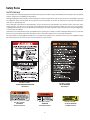
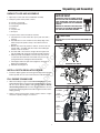
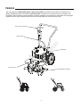
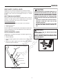
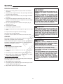
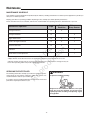
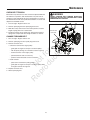
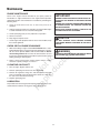
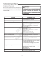
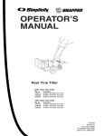
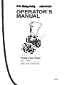
R
N
ep o
ro t fo
du r
ct
io
n
OPERATOR’S
MANUAL
Front Tine Tiller
Mfg. No.
1695578
1695584
1695921
Description
5521FT, 5.5 TP Front Tine Tiller
5521FT, 5.5 TP Front Tine Tiller
5521FT, 5.5 TP Front Tine Tiller
1695615
Revision B
2
N
ep o
ro t fo
du r
ct
io
n
R
Table of Contents
MODEL IDENTIFICATION .......................................... 3
Start-up .................................................................. 1 0
Operating Speed .................................................... 11
Shutting Down ........................................................ 11
Tilling ...................................................................... 1 1
SAFETY RULES ......................................................... 4
Owner's Responsibility ............................................. 4
Special Messages .................................................... 4
Important Safety Precautions ................................... 4
Preparation ............................................................... 4
Operation ................................................................. 5
Maintenance and Storage ........................................ 5
Safety Decals ........................................................... 6
MAINTENANCE......................................................... 12
Maintenance Schedule............................................12
Servicing the Rototiller............................................. 12
Check Belt Tension ................................................ 13
Change Forward Belt ............................................. 13
Engine Maintenance .............................................. 14
Check or Fill Engine Crankcase ............................. 14
Clean Tine Axle Shaft ............................................ 14
Lubrication .............................................................. 14
UNPACKING AND ASSEMBLY................................. 7
Unpack Tiller and Assemble ..................................... 7
Install Depth Regulator Lever .................................... 7
Fill Engine Crankcase .............................................. 7
STORAGE ................................................................. 15
Prepare for Storage................................................ 15
FEATURES ................................................................. 8
CONTROLS ................................................................ 9
Drive Safety Control Lever ....................................... 9
Belt Tension Adjustment ............................................ 9
Depth Regulator Lever ............................................. 9
TROUBLESHOOTING AND REPAIR ....................... 16
Troubleshooting Guide ............................................ 16
N
ep o
ro t fo
du r
ct
io
n
TECHNICAL MANUALS ........................................... 17
WARRANTY............................................................... 18
OPERATION ............................................................. 10
Pre-Start Inspection ............................................... 10
MODEL IDENTIFICATION
ROTOTILLER REFERENCE DATA
Record your model number, manufacturer number and
serial number in the space provided for easy reference.
The model and manufacturer numbers can be found on
the unit I.D. plate located on the unit's left engine mount.
Refer to the Engine Owner's Manual for location of
engine serial number.
Model Description/Number
If you have a service problem requiring special
assistance, contact a local dealer for help.
M/N (Manufacturer's Number)
S/N (Serial Number)
Dealer Name
Date Purchased
R
ENGINE REFERENCE DATA
Engine Make/Model
Engine ID/Serial Number
WARNING
You must read, understand and comply with all
safety and operating instructions in this manual
before attempting to setup and operate your
rototiller.
Failure to comply with all safety and operating
instructions can result in loss of machine control,
serious personal injury to you and/or bystanders,
and risk of equipment and property damage. The
triangle in the text signifies important cautions
or warnings which must be followed.
WARNING
Engine exhaust from this product contains
chemicals known, in certain quantities, to cause
cancer, birth defects, or other reproductive harm.
3
Safety Rules
OWNER’S RESPONSIBILITY
! DANGER
Accurate assembly and safe and effective use of the rototiller is the
owner’s responsibility.
s
Read and follow all safety instructions.
s
Carefully follow all assembly instructions.
s
Maintain the tiller according to directions and schedule included
in this Earthquake operator’s manual.
s
Ensure that anyone who uses the tiller is familiar with all
controls and safety precautions.
DANGER INDICATES A SERIOUS INJURY OR FATALITY WILL RESULT IF THE SAFETY INSTRUCTIONS THAT FOLLOW THIS SIGNAL WORD ARE
NOT OBEYED.
! WARNING
WARNING INDICATES A SERIOUS INJURY OR FATALITY COULD RESULT IF THE SAFETY INSTRUCTIONS THAT FOLLOW THIS SIGNAL WORD ARE
NOT OBEYED.
SPECIAL MESSAGES
Your manual contains special messages to bring attention to potential
safety concerns, machine damage as well as helpful operating and
servicing information. Please read all the information carefully to avoid
injury and machine damage.
! CAUTION
NOTE: General information is given throughout the manual
that may help the operator in the operation or service of the
machine.
CAUTION INDICATES YOU CAN OR YOUR EQUIPMENT CAN BE HURT IF THE SAFETY INSTRUCTIONS THAT FOLLOW THIS SIGNAL WORD ARE
NOT OBEYED.
N
ep o
ro t fo
du r
ct
io
n
IMPORTANT SAFETY PRECAUTIONS
Please read this section carefully. Operate the tiller according to the
safety instructions and recommendations outlined here and inserted
throughout the text. Anyone who uses this tiller must read the instructions and be familiar with the controls. Your tiller is equipped with a
safety device that enables you to stop the wheels and tines quickly
in an emergency. Learn how the drive safety control lever operates
and how to control the tiller at all times.
IMPORTANT
IMPORTANT INDICATES HELPFUL INFORMATION
FOR PROPER ASSEMBLY, OPERATION, OR
MAINTENANCE OF YOUR EQUIPMENT.
This symbol points out important safety instructions
which if not followed could endanger your personal
safety. Read and follow all instructions in this manual
before attempting to operate this equipment.
s
! WARNING
Do not allow children to operate this rototiller. Keep small children away
from the area being tilled. Do not allow adults to operate the tiller without
proper instruction.
PREPARATION
Dress appropriately when operating the tiller. Always wear sturdy
footwear. Never wear sandals, sneakers, or open shoes, and never
operate the tiller with bare feet. Do not wear loose clothing that
might get caught in moving parts.
s
Carefully inspect the area to be tilled and remove all foreign objects.
Do not till above underground water lines, gas lines, electric cables,
or pipes. Do not operate the tiller in soil with large rocks and foreign
objects which can damage the equipment.
s
Disengage all clutches and leave all control levers in the neutral
position before starting the engine.
s
Handle fuel with care; it is highly flammable.
R
s
a. Use an approved fuel container.
b. Never add fuel to a running engine or hot engine.
4
YOU MUST READ, UNDERSTAND AND COMPLY WITH
ALL SAFETY AND OPERATING INSTRUCTIONS IN
THIS MANUAL BEFORE ATTEMPTING TO SETUP
AND OPERATE YOUR ROTOTILLER.
FAILURE TO COMPLY WITH ALL SAFETY AND
OPERATING INSTRUCTIONS CAN RESULT IN LOSS
OF MACHINE CONTROL, SERIOUS PERSONAL
INJURY TO YOU AND/OR BYSTANDERS, AND RISK
OF EQUIPMENT AND PROPERTY DAMAGE. THE
TRIANGLE IN THE TEXT SIGNIFIES IMPORTANT
CAUTIONS OR WARNINGS WHICH MUST BE
FOLLOWED.
CALIFORNIA PROPOSITION 65 WARNING
ENGINE EXHAUST FROM THIS PRODUCT
CONTAINS CHEMICALS KNOWN TO THE STATE
OF CALIFORNIA TO CAUSE CANCER, BIRTH
DEFECTS, OR OTHER REPRODUCTIVE HARM.
Safety Rules
c. Fill fuel tank outdoors with extreme care. Never fill fuel
tank indoors.
IMPORTANT
THE RIGHT AND LEFT SIDES OF YOUR
ROTOTILLER ARE DETERMINED FROM
THE OPERATING POSITION AS YOU
FACE THE DIRECTION OF FORWARD
TRAVEL.
ENGINE IS SHIPPED FROM FACTORY
WITHOUT OIL.YOU MUST ADD ENGINE
OIL BEFORE STARTING ENGINE.
d. Replace gasoline cap securely and clean up spilled fuel
before restarting.
s
Never attempt to make any adjustments while the engine is
running.
OPERATION
s Do not operate the tiller under the influence of alcohol or
drugs.
MAINTENANCE AND STORAGE
s Keep hands, feet, and clothing away from rotating parts. Keep
clear of tiller tines at all times.
s Keep machine, attachments, and accessories in safe working
condition.
s Tines rotate when tiller is engaged, tines rotate when the drive
safety control lever is pulled down. Releasing the drive safety
control lever to neutral stops the tines.
s Check shear bolts, engine mounting bolts, and other bolts at
frequent intervals for proper tightness to be sure the equipment
is in safe working condition.
s Use extreme caution when operating on or crossing gravel
drives, walks, or roads. Stay alert for hidden hazards or
traffic.
s To prevent accidental starting, always disconnect and secure
the spark plug wire from the spark plug before performing tiller
maintenance.
N
ep o
ro t fo
du r
ct
io
n
s Never operate the tiller without guards, covers, and hoods in
place.
s After striking a foreign object, stop the engine, remove the
wire from the spark plug, thoroughly inspect the tiller for
any damage, and repair the damage before restarting and
operating the tiller.
s If vegetation clogs the tines, STOP THE ENGINE AND
DISCONNECT THE SPARK PLUG WIRE before removing
vegetation by hand.
s Engine muffler will be hot from operation. Do not touch it with
bare skin or a severe burn may result.
s Never run the engine indoors. Exhaust fumes are deadly.
s Always allow muffler to cool before filling fuel tank.
s Never store equipment with gasoline in the tank inside a closed
building where fumes may reach an open flame or spark. Allow
the engine to cool before storing in any building.
s Always refer to the operator’s guide instructions for important
details if the tiller is to be stored for an extended period.
s If the unit should start to vibrate abnormally, stop the engine
and check immediately for the cause. Vibration is generally a
warning of trouble.
s Do not run the engine indoors; exhaust fumes are deadly.
R
s Do not overload the machine capacity by attempting to till too
deep at too fast a rate.
s Never allow bystanders near the unit.
s Never operate the tiller without good visibility or light.
s Be careful when tilling in hard ground. The tines may catch in
the ground and propel the tiller forward. If this occurs, let go
of the handlebars and do not restrain the machine.
s Take all possible precautions when leaving the machine
unattended. Disengage all control levers, stop the engine,
wait for all moving parts to stop, and make certain guards
and shields are in place.
s When leaving the operating position for any reason:
- shut off the engine.
- wait for all moving parts to stop.
5
Safety Rules
SAFETY DECALS
This rototiller unit has been designed and manufactured to provide you with the safety and reliability you would expect from an industry
leader in outdoor power equipment manufacturing.
Although reading this manual and the safety instructions it contains will provide you with the necessary basic knowledge to operated
this equipment safely and effectively, we have placed several safety labels on the tiller to remind you of this important information
while you are operating the unit.
These important safety labels are illustrated below, and are shown here to help familiarize you with the location and content of the
safety messages you will see as you perform normal tilling operations. Please review these labels now. If you have any questions
regarding their meaning or how to comply with these instructions, reread the complete safety instruction text on the preceding pages,
or contact your local dealer.
Should any of the safety labels become unreadable because of being worn, faded, or otherwise damaged during the use of your tiller,
please use the part number information provided to order a replacement label from your local authorized dealer.
R
N
ep o
ro t fo
du r
ct
io
n
The safety labels are easily applied, and will act as a constant visual reminder to you, and others who may use the equipment. Follow
the safety instructions necessary for safe, effective operation of your rototiller.
Part No. 1737283
TINES DANGER/OPERATION
Hood Decal
Part No. 1737285
WARNING
Belt Cover Decal
Part No. 1737284
HOOD WARNING
Hood Decal
Part No. 1737287
WARNING
Pivot Mount Decal
6
Part No. 1737288
CLUTCH ENGAGE
Handlebar Decal
Unpacking and Assembly
UNPACK TILLER AND ASSEMBLE
IMPORTANT
1. Open top of carton and remove handlebar assembly.
THE RIGHT AND LEFT SIDES OF YOUR
ROTOTILLER ARE DETERMINED FROM
THE OPERATING POSITION AS YOU
FACE THE DIRECTION OF FORWARD
TRAVEL.
ENGINE IS SHIPPED FROM FACTORY
WITHOUT OIL.YOU MUST ADD ENGINE
OIL BEFORE STARTING ENGINE.
2. Find parts packet. Parts packet contains:
6- 5/16-18 x 1-3/4” bolts
6- 5/16” spring lockwashers
2- hand knobs
4- locknuts
2- 1/2” push nuts
1- detent pin
3. Cut open end of carton and remove machine:
! CAUTION
a. Install wheels on each end of axle, tap on push nuts with a
hammer.
b. Assemble tines to unit, inside tines first. Sharp edge of tine
will be away from operator at top or face down at front of
machine.
c. Outside tines have two positions- wide 21” & narrow 16”. For
narrow width - assemble with short side of tine holder pipe
towards center of machine.
d. For wide width - move left tine to right side and right to left
side. Assemble with long half of tine pipe towards machine.
e. Slide top handle of handlebar over lower loop. Put 5/16-18
x 1-3/4” bolts thru both holes from inside out, put on 5/16”
spring lockwashers and tighten with hand knobs.
N
ep o
ro t fo
du r
ct
io
n
DO NOT TRY TO LIFT THE ROTOTILLER FROM THE
CARTON.
f. Check upper and lower jam nuts for tightness. See page 9,
Belt Tension Adjustment.
g. Add and check engine oil.
NARROW TINE WIDTH
INSTALL DEPTH REGULATOR LEVER
1. Install the depth regulator lever through hole in bracket from the
bottom up with curve to rear of unit and secure with detent pin.
FILL ENGINE CRANKCASE
1. Add oil according to engine manual. Do not overfill. Use a clean,
high quality detergent oil. Container must be marked A.P.I. Service
SF - SJ. Use no special additives with recommended oils. Do not
mix oil with gasoline. Oil level must be full. Check the oil level
by removing oil fill plug. Oil level should be up to the bottom of the
fill plug opening.
R
WIDE TINE WIDTH
upper
handlebar
2. Always check oil level before starting engine. Refer to engine
manual for capacity and type of oil to use.
lower
handlebar
loop
hand knob
depth
regulator
lever
detent pin
7
Features
The advantage of the Simplicity/Snapper™ gear drive rototiller over other front tine tillers, is the exclusive unfolding and flexible drag bar. This gives the gear drive tiller its stability and its versatility. For easy transport, fold
the wheels under the engine. During operation, the wheels unfold back and the drag bar folds down. The long length
between the tines and the drag bar make this the most comfortable front tine tiller on the market.
drive safety control lever
hand knob
3-way adjustable tine widths
R
front belt cover
N
ep o
ro t fo
du r
ct
io
n
forward cable
8
Controls
DRIVE SAFETY CONTROL LEVER
! CAUTION
Engage tines into forward, releasing returns machine to neutral.
Pulling down on drive safety control lever engages the tines. Releasing
the drive safety control lever disengages the tines to a neutral
position.
BELT TENSION ADJUSTMENT
Proper belt tension is critical to good performance. After 1/2 hour of
operation, all cables may have to be adjusted due to initial stretch.
Thereafter, check tension after every 2 hours of operation.
To increase belt tension:
1. Loosen upper jam nut. Turn nut up cable in 1/8” increments.
3. Check adjustment.
This procedure can be repeated until conduit adjustment bolts have
no more adjustment left. If no more adjustment can be made, belt
may have to be replaced.
! WARNING
ENGINE SHOULD BE OFF BEFORE ADJUSTING
ANY CONTROLS.
N
ep o
ro t fo
du r
ct
io
n
DEPTH REGULATOR LEVER
Tilling depth is controlled by the height of the depth regulator lever.
1. Remove detent pin.
s AS A SAFETY PRECAUTION, THE DRIVE SAFETY
CONTROL LEVER WILL NOT LOCK IN THE
FORWARD POSITION.
s TO STOP THE WHEELS AND TINES AT ANY TIME
RELEASE THE DRIVE SAFETY CONTROL LEVER.
2. Tighten lower jam nut.
To adjust tilling depth.
THIS INFORMATION IS PROVIDED HERE ONLY TO
INTRODUCE THE CONTROLS. DO NOT START THE
ENGINE AT THIS TIME. STARTING AND OPERATING
INSTRUCTIONS ARE GIVEN ON PAGE 10. PLEASE
READ THIS SECTION AND ALL OPERATING AND
SAFETY INSTRUCTIONS BEFORE STARTING YOUR
TILLER.
DO NOT ADJUST TILLING DEPTH UNLESS DRIVE
SAFETY CONTROL LEVER IS RELEASED TO THE
NEUTRAL POSITION.
2. Raise the depth regulator lever to position tines at chosen tilling
depth.
3. Align hole in depth regulator lever with hole in depth regulator
bracket and replace detent pin.
drive safety control lever disengaged
R
1/4” stretch
upper jam nut
lower jam nut
forward cable
Model 5521 Handlebar
9
Operation
PRE-START INSPECTION
IMPORTANT
1. Make sure all safety guards are in place and all nuts and bolts
are secure.
2. Check oil level in engine crankcase. See your engine manual for
procedure and specifications.
3. Inspect air cleaner for cleanliness. See your engine manual for
procedure.
4. Check the fuel supply. Fill the fuel tank no closer than 1 inch
from top of tank to provide space for expansion. See your engine
manual for fuel recommendations.
5. Be sure spark plug wire is attached and spark plug is
tightened securely.
ENGINE IS SHIPPED FROM FACTORY WITHOUT OIL.
YOU MUST ADD ENGINE OIL BEFORE STARTING
ENGINE.
PRACTICE OPERATING THE CONTROLS AND
TILLER WITH TINES OUT OF GROUND BEFORE
BEGINNING TO TILL. IT IS IMPORTANT THAT YOU
KNOW HOW TO USE THE TILLER PROPERLY, KEEP
CONTROL AT ALL TIMES, STOP THE TINES AND
WHEELS FROM TURNING, AND STOP THE ENGINE
IF NECESSARY. IF YOU DO NOT KNOW HOW TO
DO THESE THINGS, READ THE CONTROLS AND
SAFETY SECTIONS BEFORE PROCEEDING.
6. Check position of wheels.
! CAUTION
7. Check depth regulator lever position.
8. Examine underneath and around engine for signs of oil or fuel
leaks.
9. Inspect fuel hoses for tightness and fuel seepage.
N
ep o
ro t fo
du r
ct
io
n
10. Look for signs of engine damage.
11. Remove excessive debris from muffler area and recoil starter.
START-UP
The controls required to start and run the rototiller are located on the
engine and are marked “Choke” and “Throttle”.
A more detailed description of engine operation and all related
precautions and procedures can be found in the engine manufacturer’s
manual that accompanies each tiller.
COLD STARTS
1. Move choke lever to full choke position.
2. Move throttle lever to “start”.
3. Pull starting rope out slowly one time and allow to return
normally.
4. Pull starting rope out rapidly, and allow rope to return normally.
R
5. When engine starts, gradually move choke lever to “no choke”
position and increase throttle speed.
RESTARTING A WARM ENGINE
PLEASE DO NOT START YOUR TILLER UNTIL YOU
HAVE READ THE MANUAL THAT CAME WITH YOUR
ENGINE, AND THE SECTIONS IN THIS MANUAL
TITLED CONTROLS AND SAFETY. IF YOU HAVE
READ THESE, FOLLOW THE STEPS BELOW TO
START YOUR TILLER. ALWAYS PERFORM THIS
PRE-START CHECKLIST BEFORE STARTING THE
ENGINE.
Restarting an engine that is already warm from previous running does
not normally require use of the choke.
1. Move throttle lever to “start” position.
2. Pull starting rope out rapidly until engine starts. Allow rope to return
normally. Repeat until engine starts.
3. Adjust throttle speed to “high” for best tiller action.
10
! WARNING
GASOLINE IS HIGHLY FLAMMABLE AND MUST
BE HANDLED WITH CARE. NEVER FILL THE TANK
WHEN THE ENGINE IS HOT OR RUNNING. ALWAYS
MOVE OUTDOORS TO FILL THE TANK.
TEMPERATURE OF MUFFLER AND NEAR BY AREAS
MAY EXCEED 150° F. AVOID THESE AREAS.
DO NOT MOVE CHOKE CONTROL TO CHOKE TO
STOP ENGINE. BACKFIRE OR ENGINE DAMAGE
MAY OCCUR.
TO STOP THE ENGINE AT ANY TIME, MOVE THROTTLE CONTROL TO THE OFF POSITION. TO STOP
TINES AT ANY TIME, RELEASE DRIVE SAFETY
CONTROL LEVER TO THE NEUTRAL POSITION.
ALWAYS RELEASE DRIVE SAFETY CONTROL
LEVER TO THE NEUTRAL POSITION BEFORE
ADJUSTING THE DEPTH OF THE REGULATOR
LEVER.
Operation
OPERATING SPEED
! WARNING
For normal tilling, set the throttle lever to “fast”.
SHUTTING DOWN
To stop the engine at any time, move throttle control to the off position.
To stop wheels and tines at any time, release the drive safety control
lever to the neutral position.
TILLING
EXTREME CAUTION MUST BE TAKEN IN SELECTING TILLING DEPTH. IF YOU ATTEMPT TO TILL
TOO DEEPLY FOR SOIL CONDITIONS, THAT IS,
WITH THE DRAG STAKE IN TOO HIGH A POSITION,
LOSS OF CONTROL COULD RESULT.
IF REMOVING MATERIAL FROM THE TINES BY
HAND, STOP ENGINE AND REMOVE SPARK PLUG
WIRE FIRST.
1. Adjust the depth regulator lever to desired tilling depth.
NOTE: Raise depth regulator lever up one hole at a time,
testing tiller operation after each raise. Raising depth regulator
lever too high can result in loss of control of tiller!
2. Move the throttle control to fast.
R
N
ep o
ro t fo
du r
ct
io
n
3. Place the tiller in motion by pushing down on the drive safety control
lever--this will engage the tines.
! DANGER
ENGINE AND SURROUNDING PARTS BECOME
EXTREMELY HOT DURING NORMAL USE AND WILL
CAUSE SERIOUS BURN INJURIES IF TOUCHED
BEFORE THE ENGINE HAS COOLED.
ALLOW ENGINE TO COOL COMPLETELY BEFORE
TOUCHING THESE HOT SURFACES.
ALWAYS KEEP HANDS AND FEET CLEAR OF
ROTATING MACHINE PARTS.
11
Maintenance
MAINTENANCE SCHEDULE
Your rototiller has been designed and produced by the industry’s leading manufacturer of outdoor power equipment to provide you
with years of reliable operation.
Keeping your tiller in top running condition will prolong its life, and help you obtain optimum performance.
Please read this normal care schedule, and note the recommended care operating intervals to extend the life of your unit.
Page
Before
Each Use
Change belt tension
13
X
Change forward belt
13
Engine maintenance
14
X
X
Check or fill engine crankcase
14
X
2
Clean tine axle shaft
14
X
Lubrication
Check throttle control adjustment
EM = See engine manual
50 hours or
Every Season
X
N
ep o
ro t fo
du r
ct
io
n
Maintenance Operation
14
X
-
1
1 Adjust throttle control after first 3 hours of operation or if engine is hard to start or run-on occurs.
2 Change oil after first 5-8 hours of use, then after every 50 hours or every season. Change oil every 25
hours when operating under heavy load or in high temperatures.
SERVICING THE ROTOTILLER
! WARNING
To prevent accidental starting:
R
The following information will help you make the necessary checks
and perform the procedures required to follow the normal care
recommendations made for your rototiller unit.
If you prefer, your local authorized dealer can make these checks and
perform the required procedures for you.
Engine must be turned off and cool, and spark
plug wire must be removed and secured from
spark plug before checking and adjusting engine
or equipment.
12
Maintenance
CHECK BELT TENSION
! WARNING
Belt tension may decrease over time. It must be adjusted within the
first half hour of operation, and checked after every two hours of
operation. Proper adjustment will assure long belt life. Too much or
too little belt tension will cause premature belt failure. To check and
adjust the forward belt tension:
CHECK FORWARD BELT TENSION REGULARLY.
TOO MUCH OR TOO LITTLE TENSION WILL CAUSE
PREMATURE BELT FAILURE.
1. Turn off engine. Engine must be cool.
2. Remove spark plug wire from spark plug and secure.
3. With drive safety control lever in the neutral position, measure
length of spring when in its relaxed state.
remove belt
from front
4. Pull down on drive safety control lever and measure length of
spring when compressed. Ideal length would be 1/4” shorter.
CHANGE FORWARD BELT
1. Turn off engine. Engine must be cool.
2. Remove spark plug wire from spark plug and secure.
3. Remove front belt cover.
s remove the belt from the engine pulley:
N
ep o
ro t fo
du r
ct
io
n
- gently pull the engine recoil rope to rotate the pulley.
- with the pulley turning, force the belt out of the V-groove.
- slide the belt free of the engine pulley.
- pull the belt down and out of the way.
- push the bolt forward and out front of machine.
s install new belt:
- place belt in transmission pulley groove.
4. Replace front belt cover.
5. Attach spark plug wire.
R
- gently pull the engine recoil rope to rotate the pulley while
forcing the belt into the V-groove.
13
Maintenance
ENGINE MAINTENANCE
IMPORTANT
Refer to the engine manual included in your parts packet for
information on engine maintenance. Your engine manual provides
detailed information and a maintenance schedule for performing the
following tasks:
ENGINE IS SHIPPED FROM FACTORY WITHOUT OIL.
YOU MUST ADD ENGINE OIL BEFORE STARTING
ENGINE.
ENGINE CAN OVERHEAT AND BECOME DAMAGED
IF DEBRIS BLOCKS THE COOLING SYSTEM OR
ROTATING SCREEN.
NEVER RUN ENGINE WITHOUT COMPLETE AIR
CLEANER INSTALLED ON ENGINE.
1. Check oil level before each use or after every 8 hours of
operation.
2. Change oil after first 5-8 hours of operation. Change oil while engine
is warm. Refill with new oil of recommended grade.
4. Check spark plug yearly or every 100 hours of operation.
5. Service air cleaner.
! CAUTION
6. Keep engine and parts clean.
DO NOT OPERATE TILLER BEFORE READING
THE ENGINE MANUAL PROVIDED IN THE PARTS
PACKET.
7. Check engine and equipment often for loose nuts and bolts, keep
these items tightened.
CHECK OR FILL ENGINE CRANKCASE
1. Add oil according to engine manual. Do not overfill. Use a clean,
high quality detergent oil. Container must be marked A.P.I. Service
SF - SJ. Use no special additives with recommended oils. Do not
mix oil with gasoline. Oil level must be full. Check the oil level
by removing oil fill plug. Oil level should be up to the bottom of the
fill plug opening on most engines.
! WARNING
N
ep o
ro t fo
du r
ct
io
n
TEMPERATURE OF MUFFLER AND NEAR BY AREAS
MAY EXCEED 150° F. AVOID THESE AREAS.
2. Always check oil level before starting engine. Refer to engine
manual for capacity and type of oil to use.
CLEAN TINE AXLE SHAFT
1. Turn off engine. Engine must be cool.
2. Remove spark plug wire and secure from spark plug.
3. Remove all vegetation, string, wire, and other material that may
have accumulated on the axle between the inside set of tines and
the seal on the transmission housing.
4. Replace spark plug wire.
LUBRICATION
R
Proper lubrication of moving mechanical parts is critical for proper care
and maintenance. Oil the moving parts using a 30 weight oil.
14
Maintenance
PREPARE FOR STORAGE
! WARNING
Follow the steps below to prepare your tiller for storage. Read your
engine manual for detailed instructions on preparing the engine for
storage.
DO NOT STORE TILLER IN AN UNVENTILATED
AREA WHERE FUEL FUMES MAY REACH FLAME,
SPARKS, PILOT LIGHTS OR AN IGNITED OBJECT.
DRAIN FUEL OUTDOORS AWAY FROM ANY
IGNITION SOURCES. USE ONLY APPROVED FUEL
CONTAINERS.
1. Protect wheels and axles from rust:
- Coat the axles lightly with axle grease.
2. Drain fuel system completely following engine manufacturer’s
instructions or add fuel stabilizer to prevent fuel from gumming up
during extended storage period.
3. While engine is still warm, drain the oil from the engine. Refill with
fresh oil of the recommended grade.
4. Clean external surfaces, engine and cooling fan.
5. Remove spark plug, pour one ounce of SAE 30 oil into spark plug
hole.
6. Plug hole and pull starter cord slowly to distribute oil evenly in
cylinder head area.
7. Reinstall spark plug.
N
ep o
ro t fo
du r
ct
io
n
8. Transport unit to a suitable storage location. If you have chosen to
use a fuel stabilizer and have not drained the fuel system, follow all
safety instructions storage precautions in this manual to prevent the
possibility of fire from the ignition of gasoline fumes. Remember,
gasoline fumes can travel to distant sources of ignition and ignite,
causing risk of explosion and fire.
R
9. If there is any possibility of unauthorized use or tampering, remove
the spark plug and store it in a safe place before storing the rototiller
unit. Be sure to plug the spark plug hole to prevent foreign material
from entering.
15
Truobleshooting and Repair
TROUBLESHOOTING GUIDE
! WARNING
While normal care and routine maintenance will extend the life of
your rototiller, prolonged or constant use may eventually require
that service be performed to allow it to continue operating properly.
The troubleshooting guide below lists the most common problems,
causes and remedies.
PRACTICE SAFETY AT ALL TIMES. ENGINE MUST BE
TURNED OFF AND ALLOWED TO COOL, AND SPARK
PLUG WIRE MUST BE DISCONNECTED AND SECURED
BEFORE ATTEMPTING ANY MAINTENANCE OR
REPAIR.
FAILURE TO COMPLY WITH THIS SAFETY REQUIREMENT
CAN RESULT IN SERIOUS PERSONAL INJURY TO YOU
OR BYSTANDERS.
PROBLEM
REMEDY/ACTION
s Add gas to gas tank.
s Connect spark plug wire to spark plug
s Throttle must be positioned at choke for a cold start
Engine runs rough, floods during operation
s Clean or replace air cleaner
Engine is hard to star t
s Drain old fuel and replace with fresh. Use gas stabilizer
at end of season
s Make sure spark plug wire is securely attached to spark
plug
s Drive safety control lever must be released to neutral
to start the engine
N
ep o
ro t fo
du r
ct
io
n
Engine will not star t
s Raise the tines for shallow tilling by raising the depth
regulator lever
s Clean or replace air cleaner
s Improper carburetor adjustment, take to authorized
engine service center
s Replace spark plug and adjust gap
s Drain and refill gas tank and carburetor
Engine misses or lacks power
Engine will not stop when throttle control is positioned at stop s See engine manual to check and adjust throttle linkage
s Drive safety control lever must be released to neutral
to start the engine
Tiller is difficult to control when tilling
(machine jumps or lurches forward)
s Lower engine speed in hard ground
s Raise the tines for shallower tilling by lowering the
depth regulator lever
Belts squeal in neutral
R
Tiller moves forward during star ting
s Adjust forward belt guide:
- turn engine off and allow muffler to cool
- disconnect spark plug wire and secure from spark plug
- pull down on drive safety control lever
- manually bend forward belt guide so there is 1/16 inch
or less clearance between belt guide and belt
- replace spark plug wire
Belts squeal in forward operation
s Turn engine off and allow muffler to cool
s$ISCONNECTSPArk plug wire and secure from spark plug
s2ELEASEDrive safety control lever to neutral
s!DJUSTENGAGECAble
s2EPLACESPArk plug wire
Excessive heat build up in transmission/tine area during tilling
s2EMove vegetation
s#HEck transmission fluid and fill if needed
16
Technical Manuals
Additional Technical Literature Available
Additional copies of this manual are available, as well as
fully illustrated parts lists. These manuals show all of the
product’s components in exploded views (3D illustrations
which show the relationship of parts and how they go
together) as well as part numbers and quantities used.
Important assembly notes and and torque values are
also included.
R
N
ep o
ro t fo
du r
ct
io
n
Technical manuals can be downloaded from:
www.simplicitymfg.com
www.snapper.com.
17
BRIGGS & STRATTON POWER PRODUCTS GROUP, L.L.C. OWNER WARRANTY POLICY
LIMITED WARRANTY
Briggs & Stratton Power Products Group, LLC will repair and/or replace, free of charge, any part(s) of the equipment that is
defective in material or workmanship or both. Briggs & Stratton Corporation will repair and/or replace, free of charge, any
part(s) of the Briggs and Stratton engine* (if equipped) that is defective in material or workmanship or both. Transportation
charges on product submitted for repair or replacement under this warranty must be borne by purchaser. This warranty is
effective for the time periods and subject to the conditions stated below. For warranty service, find the nearest Authorized
Service Dealer using our dealer locator at www.BriggsandStratton.com or www.Murray.com.
There is no other express warranty. Implied warranties, including those of merchantability and fitness for a particular
purpose, are limited to one year from purchase or to the extent permitted by law. Liability for incidental or consequential
damages are excluded to the extent exclusion is permitted by law.
Some states or countries do not allow limitations on how long an implied warranty lasts, and some states or countries do
not allow the exclusion or limitation of incidental or consequential damages, so the above limitation and exclusion may not
apply to you. This warranty gives you specific legal rights and you may also have other rights which vary from state to state
or country to country.
WARRANTY PERIOD
Item
Equipment
Engine*
Battery
Consumer Use
2 Years
2 Years
1 Year
Commercial Use:
90 Days
90 Days
1 Year
N
ep o
ro t fo
du r
ct
io
n
The warranty period begins on the date of purchase by the first retail consumer or commercial end user, and continues for the
period of time stated above. “Consumer use” means personal residential household use by a retail consumer. “Commercial
use” means all other uses, including use for commercial, income producing or rental purposes. Once product has experienced
commercial use, it shall thereafter be considered as commercial use for purposes of this warranty.
No warranty registration is necessary to obtain warranty on Briggs & Stratton products. Save your proof of purchase receipt. If you
do not provide proof of the initial purchase date at the time warranty service is requested, the manufacturing date of the product will
be used to determine warranty eligibility.
ABOUT YOUR WARRANTY
We welcome warranty repair and apologize to you for being inconvenienced. Warranty service is available only through servicing
dealers authorized by Briggs & Stratton or BSPPG, LLC.
Most warranty repairs are handled routinely, but sometimes requests for warranty service may not be appropriate. This warranty
only covers defects in materials or workmanship. It does not cover damage caused by improper use or abuse, improper
maintenance or repair, normal wear and tear, or stale or unapproved fuel.
R
Improper Use and Abuse - The proper, intended use of this product is described in the Operator’s Manual. Using the product in
a way not described in the Operator’s Manual or using the product after it has been damaged will void your warranty. Warranty is
not allowed if the serial number on the product has been removed or the product has been altered or modified in any way, or if the
product has evidence of abuse such as impact damage, or water/chemical corrosion damage.
Improper Maintenance or Repair - This product must be maintained according to the procedures and schedules provided in the
Operator’s Manual, and serviced or repaired using genuine Briggs & Stratton parts. Damage caused by lack of maintenance or use
of non-original parts is not covered by warranty.
Normal Wear - Like all mechanical devices, your unit is subject to wear even when properly maintained. This warranty does not
cover repairs when normal use has exhausted the life of a part or the equipment. Maintenance and wear items such as filters,
belts, cutting blades, and brake pads (engine brake pads are covered) are not covered by warranty due to wear characteristics
alone, unless the cause is due to defects in material or workmanship.
Stale Fuel - In order to function correctly, this product requires fresh fuel that conforms to the criteria specified in the Operator’s
Manual. Damage caused by stale fuel (carburetor leaks, clogged fuel tubes, sticking valves, etc) is not covered by warranty.
* Applies to Briggs and Stratton engines only. Warranty coverage of non-Briggs and Stratton engines is provided by the engine manufacturer.
EN
1737660 Rev B
18
19
N
ep o
ro t fo
du r
ct
io
n
R
N
ep o
ro t fo
du r
ct
io
n
R
www.simplicitymfg.com
www.snapper.com
Briggs & Stratton Power Products Group, L.L.C.
Copyright © 2011 Briggs & Stratton Corporation
Milwaukee, WI USA. All Rights Reserved
www.BRIGGSandSTRATTON.com