1
ELK-M1XRFTW
Two-Way Wireless Transceiver/ Expander
for Elk Two-Way Wireless Sensors.
Refer to page 8 for a listing of sensor part numbers.
INSTALLATION
MANUAL
IMPORTANT NOTE:
ELK-M1G and M1EZ8 Controls require application firmware ver. 5.2.10 or higher
to be compatible with the M1XRFTW Receiver. Refer to Elk's website for "flash" file updates.
For the very latest downloadable version of this manual please go to our website:
http://www.elkproducts.com
L644 Rev. A 2/1/2013
PO Box 100
3266 US Hwy 70 West
Hildebran, NC 28637
828-397-4200 828-397-4415 Fax
http://www.elkproducts.com
Table of Contents
Installation and Setup ................................................................................................................... 4
Diagnostic LED Indicators ........................................................................................................................ 4
Setting the Data Bus Address and the Starting Wireless Zone ID ............................................................ 5
Data Bus Enrollment:: .............................................................................................................................. 6
Operation ....................................................................................................................................... 7
How does the Elk Two-Way technology differ from one-way wireless technology? ................................. 7
Elk 6000 Series Wireless Sensors................................................................................................ 8
'Quick Step' Enrollment of Elk 6000 Series Sensors .................................................................. 9
M1 Keypad Programming for the M1XRFTW ............................................................................ 10
Appendix A - Data Bus Selection Table ..................................................................................... 12
Appendix B - Examples of Zone Configurations ...................................................................... 13
Appendix C - Installing Multiple Redundant M1XRFTW Transceivers .................................... 14
Appendix D - Updating Firmware in the ELK-M1XRFTW ......................................................... 15
FEATURES:
• Adds up to 144 individual wireless zones (sensors/points)
• Operates from the 4 wire RS485 Data Bus
• Multiple Transceivers (Receivers) may be connected to a single Control
• Flash Memory allows field updating of operating Firmware
• Compatible with Elk complete line of Two-Way Wireless Sensors.
SPECIFICATIONS:
• Operating Frequency: 902 Mhz to 928 Mhz
• Transmission Duration (active on-time): 50 ms
• Sensitivity: >105 dbm
• Operating Temperature: 0 to +120 degrees F
• Operating Voltage: 12 Volts D.C.
• Current Draw: 25mA Receiving, 85mA Transmitting
FCC COMPLIANCE STATEMENT:
This device complies with Part 15 of the FCC Rules. Operation is subject to the following two conditions:
(1) this device may not cause harmful interference, and
(2) this device must accept any interference received, including interference that may cause undesired operation.
Part Number
ELK-M1XRFTW
ELK-6010
ELK-6020
ELK-6021
ELK-6022
Description
M1 Two-Way Receiver
Wireless KeyChain Remote "FOB"
Wireless Slim-Line Door and Window Sensor
Wireless Mini Window Sensor
Wireless Universal 3-Zone Door/Window Sensor
FCC ID Number
TMA ELK-M1XRFTW
TMA ELK-6010
TMA ELK-6020
TMA ELK-6021
TMA ELK-6022
NOTE: ELK PRODUCTS IS NOT RESPONSIBLE FOR ANY CHANGES OR MODIFICATIONS NOT EXPRESSLY APPROVED BY THE PARTY RESPONSIBLE
FOR COMPLIANCE. SUCH MODIFICATIONS COULD VOID THE USER’S AUTHORITY TO OPERATE THE EQUIPMENT.
Page 2
M1XRFTW Installation Manual
OVERVIEW
The letters "TW" on the M1XRFTW signify "two-way", meaning this device is actually a transceiver rather than just a receiver.
In other words, it has the ability to both transmit and receive. The compatible Elk 6000 series two-way wireless sensors
are also two-way, making them vastly superior to traditional one-way wireless sensors. As you read through this manual,
and experience first-hand the advantages offered by Elk's "two-way" wireless products, we hope that you will share our
feelings that :"Two-way is the only way".
PLEASE NOTE: This manual references the word transceiver as well as receiver and transmitter. This is due to the fact
that M1 keypad programming and the ElkRP programming software still maintain support for traditional one-way wireless
as well as the new Elk two-way wireless products. We hope this does not cause too much confusion.
The M1XRFTW Transceiver allows M1 and M1EZ8 Controls to accept the new 6000 Series "Two-Way" Wireless Sensors.
See the listing of available sensors later in the manual. This list is constantly growing and may not be current in this manual
due to its printing date. Please contact your local Elk distributor for the latest products and information.
Including the M1XRFTW, Elk now produces three (3) different models of wireless expanders for the M1 & M1EZ8 Controls.
The M1XRFTW is compatible only with Elk's 6000 Series two-way sensors, the M1XRFEG is compatible only with GE (UTC)
one-way sensors, and the M1XRF2H is compatible only with Honeywell (Ademco) 5800 series one-way sensors. Regardless
of the model and supported wireless protocol, each connects to the M1 Control via the RS485 four (4) wire Data Bus and
becomes enrolled and integrated much the same way as a hardwired expander.
NOTE: A major difference between a wireless expander and a hardwired expander is that a single M1XRFTW ("EG"
or "2H") wireless expander is capable of supporting up to 144 wireless Sensors/Zones.
Because it is attached to the RS485 Data Bus, a wireless expander can be remotely mounted virtually anywhere in the building
to provide maximum convenience and coverage (range). And the serial number (TXID) and setup information of all sensors
is stored safely inside the control, so that if it every becomes necessary to replace a wireless expander there is little or no
programming required. Simply replace the wireless expander and perform a data bus enrollment to allow the M1 Control
to begin communicating with it.
IMPORTANT: The M1XRFTW "two-way" Transceiver must be enrolled as the first zone expander
(Address # 2) on the M1 or M1EZ8 Control Data Bus. Up to 3 additional M1XRFTW transceivers may
be connected to the M1 for expanded wireless coverage. If connected, the 1st additional M1XRFTW
transceiver must be enrolled at data bus address 3, the 2nd at data bus address 4, and the 3rd at data
bus address 5. No other addresses may be used for M1XRFTW Transceivers.
Should another model of wireless expander (M1XRFEG or M1XRF2H), OR an M1XIN hardwire
expander be currently installed at an address where an additional M1XRFTW is required then it will be
necessary to relocate (move) the other device(s) to a higher address and make room for the
M1XRFTW(s). See Appendixes A, B, & C for additional details on the use of multiple transceivers.
Retrofitting an existing installation - In a retrofit installation or takeover situation it is possible to mix various models of Elk
M1XRFx wireless expanders and their compatible sensors on a single M1 Control. This can be economically beneficial as
it prevents having to throw away or replace existing wireless sensors just to utilize another brand. BUT EXTREME CAUTION
must be taken to assure that each sensor is installed within adequate range of it's respective and compatible wireless
expander brand/model. In other words, the sensors and wireless expanders are physically and electronically different. Each
sensor can only communicate with its respective wireless expander brand/model.
IN AN INSTALLATION CONSISTING OF MIXED BRAND/MODEL WIRELESS EXPANDERS THE SENSOR
BRAND/MODEL MUST BE MATCHED TO THE CORRECT WIRELESS EXPANDER BRAND/MODEL.
M1XRFTW Installation Manual
Page 3
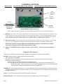
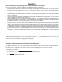
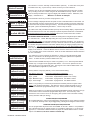
Installation and Setup
INSTALL UNIT * SET ADDRESS AND OPTION JUMPERS * ACTIVATE M1 BUS ENROLLMENT PROCESS
ANT1
On-board
Antenna
JP1 Bus
Terminating
Jumper
ELK-M1XRFEG
Data Bus
Address Switches
NOTE: ONLY addresses
2, 3, 4, or 5 should be
used with the
M1XRFTW.
ELK-M1XRFTW Two-Way Transceiver
RS-485
Data Bus
Connections
NOTE: Jumper JP1makes it convenient to terminate the RS-485 Data Bus if this is the last installed device.
1. Mounting - Two (2) #6 x 1/2" screws (not provided), one on each side of the housing should be used for mounting. The
receiver connects to the M1's Keypad data bus and may be remotely located up to several thousand feet away from the
control. DO NOT mount inside a metal enclosure or on metalized surface! Space at least 10 feet away from electrical
devices that generates noise, including the M1 Control. Electrical noise may negatively affect operation.
2. Wiring Connections - Turn the power Off on the Control Panel before making any wiring connections. Connect terminals +12V, A, B, and Neg from the receiver to the M1's Keypad Data Bus (terminals +VKP, Data A, Data B, & Neg).
NOTE: Refer to the M1 Installation Manual and the M1DBH information in that manual about proper
connections of data bus devices with multiple homerun cables.
3. Antenna - The M1XRFTW uses a single on-board ceramic antenna. There is no external antenna required.
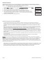
Diagnostic LED Indicators
There a four (4) LEDs on the board that provide valuable information as to the operation of the M1XRF:
STATUS (Data Bus Status) - Multiple conditions exist for this LED:
OFF = No Power to the M1XRF
ON Solid = Power is good but it is not yet enrolled with the M1 or the Microprocessor is not functioning.
BLINKING = 2 different blink rates:
- Slow "one blink per second" indicates Normal Operating mode.
- Two blips with a brief off time indicates unit is in Bootloader mode. It has not yet been flashed with the
application firmware. This should only occur if you are field updating the unit. It will not be operational
until application firmware has been flashed into the unit using ElkRP.
LEARNED RF - This LED will momentarily turn on when the M1XRF receives a valid transmitter and is in the process of
sending the signal packet back to the M1 Controller. As soon as the packet is acknowledged by the M1 Controller
the LED will turn Off.
ALL RF - This LED blinks whenever ANY Elk RF transmitter is detected.
DATA BUS ACTIVE - This LED blinks near continuously and indicates activity on the M1 Data Bus.
Page 4
M1XRFTW Installation Manual
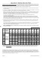
Setting the Data Bus Address and the Starting Wireless Zone ID
The M1XRFTW "two-way" transceiver must be addressed and enrolled as the 1st zone expander (Data Bus Address # 2) on
the M1 or M1EZ8 Control. For extended range and coverage up to 3 additional M1XRFTW transceivers may be installed. If
installed these must be enrolled as the 2nd, 3rd, and 4th zone expander (Data Bus Addresses 3, 4, and 5) on the M1 or M1EZ8
Control. If another hardwire or wireless expander is presently enrolled at one of these addresses it will be necessary to move
that device to another address in order to make accomodation for the M1XRFTW transceiver. Refer to Appendixes A, B, & C for
additional details on the use of multiple transceivers.
Data Bus Address Information: Every device attached to the M1 or M1EZ8 Data Bus must have a valid address setting within
it's device type. TYPE 1 is for Keypads, TYPE 2 is for Hardwire and Wireless Input expanders, TYPE 3 is for Output expanders,
TYPE 5 is for Serial expanders. This grouping of devices into different types allows devices in different groups to use the
permits same or similar address numbers to exist in each device group type. All devices except keypads utilize a bank of 4
miniature DIP switches for setting the address number. Each switch has an OFF or ON position (binary value 0 or 1) and
decimal equiv. value of (1, 2, 4, or 8). The total decimal value of the "ON" switches determines the data bus address. Set the
switches to the desired data bus address by referring to Tables 1-1 and 1-2. A small screwdriver may be helpful.
M1XIN Expander versus M1XRFTW Wireless Expanders (Transceivers):
A single ELK-M1XIN Hardwired Zone Expander (M1XIN) adds 16 hardwired zones at a time to an M1 or M1EZ8 Control. The
data bus address determines the zones numbers (starting and ending) of that group of 16 zones. See Table 1-1. If additional
M1XINs are installed each must be assigned a different address, usually the next available, which sets the zone numbers
(starting and ending) of that group of 16 zones.
A single M1XRFTW Wireless Transceiver/Zone Expander can add up to 144 wireless zones to an M1 or M1EZ8 Control.
The primary or 1st M1XRFTW must be installed and enrolled at data bus address #2, so the first wireless zone will always be
Zone 17. If the full compliment of 144 wireless zones is added then the last wireless zone will be Zone #160. (17 + 144 = 160).
It is very important that no hardwired zone expander ever be assigned a data bus address that would result in a conflict between
a wireless zone and a hardwired zone. In a mixed system of hardwired and wireless zones if any hardwired zone expanders
are enrolled in the range of zones 33 through 160 then an entire group of 16 wireless zones is lost for every hardwired (16
zone) expander installed.
M1XIN Zone Expanders
Data Bus Starting and Ending
Address
Zone Numbers
2
3
4
5
6
7
8
9
10
11
12
13
14
15
Zones 17 - 32
Zones 33 - 48
Zones 49 - 64
Zones 65 - 80
Zones 81 - 96
Zones 97 - 112
Zones 113 - 128
Zones 129 - 144
Zones 145 - 160
Zones 161 - 176
Zones 177 - 192
Zones 193 - 208
not valid
not valid
Table 1-1
M1XRFTW Wireless Expanders
Switch Settings
S1 S2 S3 S4
Off
On
Off
On
Off
On
Off
On
Off
On
Off
On
-
On
On
Off
Off
On
On
Off
Off
On
On
Off
Off
-
Off
Off
On
On
On
On
Off
Off
Off
Off
On
On
-
Off
Off
Off
Off
Off
Off
On
On
On
On
On
On
-
Data Bus
Address
Wireless "Starting
Point"
2
3
4
5
6
7
8
9
10
11
12
13
14
15
Zone 17 up to 160
Opt. 2nd M1XRFTW
Opt. 3nd M1XRFTW
Opt. 4th M1XRFTW
not valid
not valid
not valid
not valid
not valid
not valid
not valid
not valid
not valid
not valid
Switch Settings
S1 S2 S3 S4
Off
On
Off
On
Off
On
Off
On
Off
-
On
On
Off
Off
On
On
Off
Off
On
-
Off
Off
On
On
On
On
Off
Off
Off
-
Off
Off
Off
Off
Off
Off
On
On
On
-
Other Jumper
Settings:
JP1 - Used to engage
a 120 Ohm resistor
for terminating the
RS-485 Data Bus.
See Data bus wiring
instructions before
use.
Table 1-2
As seen in Tables 1-1 and 1-2, Zones 17 to 31 are associated with data bus address 2, which is where the primary (1st)
M1XRFTW must be setup and enrolled. And even though up to 144 wireless zones may be added with a single M1XRFTW, up
to 3 additional remotely mounted M1XRFTW may be installed to increase or expand the wireless coverage range. In
additional M1XRFTW units are added they must be setup and enrolled at addresses 3, 4, and 5 respectively.
Recommendation: Avoid setting up and enrolling hardwired expanders at any of the data bus addresses where a wireless
zone might someday be needed.
M1XRFTW Installation Manual
Page 5
Data Bus Enrollment::
Once the data bus address is set to "2" and the M1XRFTW has been powered up then it will be necessary to manually
ENROLL the device in order for the M1 Control to recognize it. Data bus enrollment can be done from keypad programming
"Menu 1 - Bus Module Enrollment" or from the ElkRP Remote Programming Software.
(The steps below require an M1 LCD Keypad)
12345678901234567890123456
12345678901234567890123456
12345678901234567890123456
1. Press the ELK key, then 9 (or scroll up) to display 9 - Installation Programming. Press the RIGHT
12345678901234567890123456
12345678901234567890123456
Auth. Required
12345678901234567890123456
12345678901234567890123456
arrow key to select this menu.
12345678901234567890123456
Enter Valid Pin
12345678901234567890123456
12345678901234567890123456
2. Enter the Installer Program Code. (The default code is 172839)
12345678901234567890123456
12345678901234567890123456
3. The first Installer Programming menu displayed will be "Bus Module Enrollment"
12345678901234567890123456
12345678901234567890123456
12345678901234567890123456
01-Bus Module
4. Press the RIGHT arrow key to select this menu. "Enrolling Bus Modules" will display
12345678901234567890123456
12345678901234567890123456
12345678901234567890123456
Enrollment
5. The control will transmit an enrollment message to all data bus devices, followed by a display
12345678901234567890123456
12345678901234567890123456
12345678901234567890123456
showing the total Bus Modules that are enrolled. To view the enrolled devices press the RIGHT
12345678901234567890123456
12345678901234567890123456
12345678901234567890123456
arrow key next to the word Edit.
12345678901234567890123456
XX Bus Modules
12345678901234567890123456
12345678901234567890123456
6. Press the * or Exit keys to exit Installer Programming.
12345678901234567890123456
Enrolled, Edit r
12345678901234567890123456
12345678901234567890123456
Important considerations when installing an M1XRFTW:
-
-
A single M1XRFTW wireless transceiver expander is capable of supporting up to 144 wireless Sensors/Zones.
Although wireless zones are always allocated in Groups of 16, it is not necessary to install or utilize all 16 wireless zones
in the group. However it is important to understand that NO HARDWIRED zones can exist at any of these zone number
locations.
Special care must be taken to ensure that NO wireless zone numbers spill over into data bus addresses that are already
assigned to a M1XIN Hardwired Zone Expander, or vis versa. It may be necessary to move a hardwired expander and its
related zones up higher in the numbering scheme just to make room for a group of 16 wireless zones.
Elk strongly recommends that all wireless zones be assigned consecutively. This also means that the wireless group
numbers AND the associated data bus addresses will also be consecutive. Please do not mix hardwired zone expanders
in between groups of wireless zones. The data bus addresses that are potentially vulnerable to this issue are addresses
2,3,4,5,6,7,8,9, & 10. That is because these addresses are the only locations where the wireless zones (17 thru 160) are
allowed to exist.
Zone 160 is the highest wireless zone number allowed. Expressed another way, wireless zones cannot exist in the range
of 161 through 208.
Should a large number of wireless zones be anticipated then it would be wise to AVOID any of these potentially
overlapping data bus addresses (zones) when assigning a hardwired expander.
Example: Let's say we are installing an M1 Control with 64 Elk-M1XRFTW wireless zones. The first zone must begin at
Zone #17 and this is because the M1XRFTW must be assigned at data bus address 2. Starting from 17 and adding 64 zones
means that the last wireless zone would be zone #80. Zone #80 happens to be the last zone in the data bus address #5
location. Therefore, the first available data bus address for a hardwired zone expander would be data bus address #6. NO
HARDWIRED ZONE EXPANDER COULD BE SET to data bus addresses 2, 3, 4, or 5. Each of those data bus addresses are
reserved for the 64 wireless zones.
NOTE: Always try to anticipate whether the system might someday require more wireless or hardwired zones. If the
answer is yes then it would be wise to plan the data bus address assignments in such a way that future growth is
possible without having to default the control or totally re-arrange the addresses at a future date.
Page 6
M1XRFTW Installation Manual
Operation
How does the Elk Two-Way technology differ from one-way wireless technology?
Elk's Two-Way technology is superior to traditional one-way wireless products in many ways.
1. Every signal sent by an Elk two-way sensor receives a positive acknowledgment from the transceiver. One-way systems have
the reputation of being "fire and pray".
2. Elk two-way sensors only send one signal at a time. One-way sensors have no choice but to blindly send multiple signals in
hopes that at least one will reach the receiver.
3. Long battery life and energy efficiency are inherent designs of the Elk two-way sensors. Elk two-way sensors self-adjust their
RF power, using only the minimum power needed to deliver a clear signal. One-way sensors consume FULL power on each
and every transmission.
4. Long range coverage is possible due to the 900 MHz frequency range and automatic frequency hopping design. One-way systems
operate at a specific, non-adjustable lower frequency.
5. A two-color LED indicator on the sensor provides operational feedback. A single Green blink means the transmission was sent
and positively acknowledged by the transceiver. A Red blink means the sensor was unable to receive an acknowledgment from
the M1XRFTW transceiver. One-way sensors provide no indication of signal verification.
6. Installation confidence. All Elk 6000 series sensors artificially limit their RF power to 50% of normal for the first 10 minutes after
battery installation. This "stress test" helps to assure that a sensor's mounting location and range is suitable for long term
reliability. The principle is that a sensor which is able to reliably communicate using half the normal power will have a high degree
of reliability with full 100% power. Other sensor brands do not provide this confidence feature. To take full advantage of this feature
we recommended that every sensor be temporarily installed at its intended location and tripped multiple times while observing
the two-color LED indicator. A near instant GREEN blink response from the sensor is Ideal. If it requires more than a second
or so to get a GREEN blink then we suggest reorienting the sensor to another spot on the mounting surface, or rotating its mounting
by 90 degrees. Be aware that excessive distance (range) can also cause a delay of the GREEN blink. In extreme situations it
may be necessary to relocate the transceiver to closer spot or to add an additional remote transceiver to cover distant sensors.
Programming tools needed for the M1XRFTW Transceiver and Sensors.
There are no special tools required for Elk's two-way wireless product line. The Transceiver itself and the sensors may be
programmed using either the M1 Keypad Installer Programming or the ElkRP Remote Programming software. The following pages
document the options and steps for programming from the keypad.
Installation and Replacement of Batteries in Wireless Sensors::
A Low Battery trouble will be sent to the Control whenever a sensor determines that its battery needs to be replaced. This will
generally occur well in advance of the battery becoming completely dead. However, it is up to the customer to ensure that the
Low Battery trouble is responded to and rectified in a timely manner so that the system can continue to operate.
When replacing a Low Battery:
1. Remove the old battery and WAIT AT LEAST 20 SECONDS before installing the new battery. This is important as it allows
the sensor circuitry to completely shutdown and erase the low battery memory.
2. After 20 seconds, install the new battery, then trip the sensor a couple of times so that an "all good" signal will be sent to
the control to clear the low battery trouble.
M1XRFTW Installation Manual
Page 7
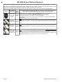
Elk 6000 Series Wireless Sensors
Enrollment and programming of wireless devices may be done from Keypad Installer Programming or from ElkRP
Enrollment from Keypad Installer Programming utilizes Menu 14 and the LRN (Learn) method. The enroll method varies between sensors. Please
follow the specific enroll method suggested below and read the additional programming recommendations.
Enrollment from the ElkRP software involves typing in the TXID (serial number of the sensor) along with selecting the particular attributes.
Keypad
Part Number(s)
From Keypad Installer Programming use Menu 14, sub-menu 3:Lrn Sel Wireless Transmitter.
Enroll
Image
& Description
Follow the published Enroll Method procedure and other steps as listed below.
Method
Elk6010 Keychain
Remote (FOB),
4 buttons with
System Status
Inquiry
Set the Supervision Type as “0”. This is mandatory! Use Menu 14, sub-menu 2:Xmit Transmitter Opt.
Program the Zone Def. as 15-KEYFOB using Menu 5:Zone Definitions.
Enroll Key (button) functions may be modified using Menu 14, sub-menu 4:KeyfobSel Event Definition.
Method By factory default key (button) 1=Arm, 2=Disarm, and 3=Inquiry (System Status).
Keys (buttons) 1,2,3,4 may be converted to respond as 5,6,7,8 by enabling Option 1 using Menu 14, sub-menu 2:Xmit
3
Transmitter Opt.
Loop # = {For keychain remotes the Loop # does not matter}
Loop # = 2 Since this is a single zone sensor the M1 default Loop # 0 will recognize the built-in reed switch immediately. It
Elk6020 Slim Door
& Window Sensor,
Front/Back Tamper
Enroll is not mandatory to change (program) the Loop from 0 to 2. However, if this sensor is replacing a previous sensor that was
Method programmed with Loop # equal to 1 or 3, this sensor will not be recognized by the M1 until the Loop is reprogrammed to a
value of 2.
1
Elk6021 Mini
Window Sensor,
No Tamper
Enroll is not mandatory to change (program) the Loop from 0 to 2. However, if this sensor is replacing a previous sensor that was
Method programmed with Loop # equal to 1 or 3, this sensor will not be recognized by the M1 until the Loop is reprogrammed to a
value of 2.
1
Elk6022 Universal
3-Zone Dr/Wnd
Sensor,1 Reed +
2 Aux. Inputs,
Front/Back Tamper
Loop # = 2 Since this is a single zone sensor the M1 default Loop # 0 will recognize the built-in reed switch immediately. It
Enroll
Method
2
ELK6030 Two-Way PIR
Motion Detector
ELK6050 Smoke Detector
Two-Way with Internal Sounder
Use Enroll Method 2
Use Enroll Method 4
Single Button Panic Xmtr
Ademco Part # 5802, 5802MN
Use Enroll Method 3 NOTE: Program Zone Def. as KEYFOB. The single button responds as KEY 4 and MUST be assigned a
functionality as Key # 4 under SubMenu 4. Consider setting the zone as non-supervised if customer is likely to carry sensor away from
the premises. This helps prevent nuisance missing transmitter troubles. Refer to WZnxxx 02 (Supervision Type).
Panic Xmtr w/Dbl Key Press
Ademco Part # 5802MN2
Enroll Manually by typing in the Xmtr ID NOTE: Select Zone and press the left arrow "HW". Type in Xmtr Decimal ID
shown on the unit. Set Loop to "1". Program Zone Def. as desired. Consider setting the zone as non-supervised if customer is likely to
carry sensor away from the premises. This prevents nuisance missing transmitter troubles. Refer to WZnxxx 02 (Supervision Type).
Holdup Switch Xmtr
Ademco Part # 5869
Enroll Manually by typing in the Xmtr ID NOTE: Select Zone and press the left arrow "HW". Type in the Xmtr Decimal ID
shown on the unit. Set Loop to "1". Since this type of holdup sensor is generally fix mounted, the zone can and should be programmed
as supervised. Refer to WZnxxx 02 (Supervision Type).
Wireless Outdoor Motion Sensor
Xmtr
Ademco Part # 5800PIR-OD
Use Enroll Method 2
Shock Sensor
Ademco Part # 5800SSI
Use Enroll Method 2
Shock Processor Xmtr,
3 Channels, 2 Ext. & 1 Reed
Sw.
Ademco Part # 5819
Glassbreak Xmtr
Ademco Part # 5853
Flood / Temperature Xmtr,
3 Channels
Ademco Part # 5821
Heat 'Rate Of Rise' Xmtr
Ademco Part # 5809
Page 8
This Sensor MUST be enrolled as a separate wireless zone for each input being used. The TXID will be the same for each.
Loop # = >>> Since this is a multi-zone sensor the Loop # directs which input on the sensor is assigned to the wireless
zone. Set the Loop # to 2 to use the built-in reed switch as the input. Set the Loop # to 1 to use the Aux. LP1 terminals as
the input. Set the Loop # to 3 to use the Aux. LP3 terminals as the input. This is very IMPORTANT!
Normally Open (N/O) contacts may be connected to the Aux. Inputs LP1 & LP3 by enabling Option 2 under Menu 14, submenu 2:Xmit Transmitter Opt. For additional information see instructions packed with sensor.
Use Enroll Method 2B NOTE: This Xmtr has 3 inputs and can be enrolled into 3 zones. The inputs have Loop # assignements
which must be set for each zone. The 1st zone could be Loop 1, the 2nd Loop 2, and the 3rd Loop 3. See sensor instructions. Repeat
the enroll process each of the other zones prior to setting their Loop #. Ext. inputs are N/C by default, but can be changed to N/O by
setting zone option WZnxxx 04 (Enable Option 2) to YES.
Use Enroll Method 2
Use Enroll Method 2B NOTE: This Xmtr can be configured as a stand-alone temperature sensor and/or as either a Remote
Temperature Sensor OR Flood Detector. Each channel must have its own zone and Loop # assignment of 1, 2, or 3. Refer to sensor
instructions. Repeat the enroll process for each of the other zones prior to setting their Loop #.
Use Enroll Method 4
M1XRFTW Installation Manual
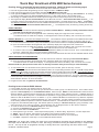
'Quick Step' Enrollment of Elk 6000 Series Sensors
Enrolling Sensors from the M1 Keypad Installer Programming (additional details on following pages)
NOTE: The M1XRFTW must be enrolled on the data bus at address 2.
1. From M1 Keypad Installer Programming scroll or navigate to Menu: 14-Wireless Setup
bPrgrr WirelessTransmtr
2. Press right arrow and scroll up to Sub-Menu: 3:Learn Selb
3. Press right arrow WZone and search of scroll to the first available (unused) location displaying TransmitrToLrn. An existing
or already enrolled location will display Enrolled followed by a 6 digit TXID number of the enrolled sensor.
4. After finding an available wireless zone location press the right arrow to Lrn (Enroll) a sensor into this location.
5. The keypad will display Push Transmitter Button and the M1G will announce: "Press transmitter button for zone __". On
successful enrollment the keypad will chime and the TXID will briefly display. The M1G will announce: "Zone __ Enrollment".
The Rapid-Enroll feature will advance to the next available wireless zone in sequence and wait for another sensor to be enrolled.
The M1G will announce: "Press transmitter button for zone __". The Rapid-Enroll may be exited by pressing the ELK key.
ENROLL METHOD 1 A. Insert Battery in the Sensor while M1 is displaying "Push Transmitter Button". If battery is already installed then remove
it and wait 5 seconds before re-inserting.
B. Upon successful enrollment the Keypad will chime and briefly display the 6 digit TXID code of the Sensor.
- If enrollment FAILS the TXID will not display. If that happens then remove the battery, wait 5 seconds, then re-insert.
ENROLL METHOD 2 - For Sensors with Multiple Zone Inputs. The enrollment must be repeated for each additional Zone Input.
The TXID will be the same for each. We strongly recommend enrolling the additional zone(s) in sequence with the 1st.
A. For the internal reed switch Zone (LP2) insert the Battery into the Sensor while M1 is displaying Push Transmitter Button.
B. Upon successful enrollment the Keypad will chime and briefly display the 6 digit TXID code of the Sensor.
- If enrollment FAILS the TXID will not display. If that happens then remove the battery, wait 5 seconds, then re-insert.
The Rapid-Enroll feature will auto advance to the next wireless zone.
C. To enroll the next Zone (marked LP1) on this sensor REMOVE the Battery and wait 5 seconds. Then re-insert Battery into
the sensor. Repeat this step to enroll the next Zone (marked LP3).
D. The Loop # must be progammed uniquely for each input since the TXID will be the same for all 3 available wireless zones.
ENROLL METHOD 3 - KEYCHAIN REMOTES
A. PRESS and HOLD button 1 or button 2 on the Keychain Remote while M1 is displaying Push Transmitter Button.
B. Upon successful enrollment the Keypad will chime and briefly display the 6 digit TXID code of the Sensor.
- If enrollment FAILS the TXID will not display. If that happens then remove the battery, wait 5 seconds, then re-insert.
NOTE: If the M1 Lrn (Enroll) function times out or is manually exited then It may be necessary to restart from Step 1
6. To end Rapid-Enroll once all wireless zones (sensors) have been enrolled, press the ELK key one time.
7. Loop # - For internal reed sensors like the ELK-6020 and 6021, the Loop # setting should be set to 2, but the M1 factory default
loop value of 0 will actually recognize the reed switch without the need of changing the Loop from 0 to 2. For multi-zone sensors
like the ELK-6022 it is VERY IMPORTANT to set the Loop #. For Keychain remotes the Loop # setting does not matter!
To set the Loop # scroll up or down to the desired M1 wireless zone and press the left arrow. The screen will display a 9 digit
number (the TXID in decimal) followed by Loop=. Press the right arrow and move cursor over to Loop=. Refer to the "Elk 6000
Series Wireless Sensors" for more information.
8. Program the Zone Def. using Menu 5: Zone Definitions.
Enrolling Sensors from the ElkRP Software
1. Launch ElkRP and open the desired Customer Account file.
2. If no wireless zones currently exist in the M1 you will first need to create a group of 16 wireless zones. In the folders column
right click on Zones (Inputs), then click New Wireless Zones. Select Group 2. NOTE: The first M1XRFTW must be enrolled at
data bus address 2, therefore the first wireless zone will always be Zone 17 which resides in Group 2. Additional groups of
16 zones may be added as required. It a hardwired zone expander is occupying address 2 it will have to be relocated to another
address so that the M1XRFTW can be at address 2. Up to 3 additional M1XRFTW Transceivers may added for expanded
coverage. If so, they must be enrolled at addresses 3, 4, and 5 respectively. If a large quantity of wireless zones is expected,
avoid enrolling hardwired expanders in data bus addresses below 10. This will allow for the maximum of 144 wireless zones.
3. Program the Zone Definition,Name,Type, and desired options by clicking on: Wireless Group (the group just added). Then
select each zone one at a time to program. Zones definitions may be assigned before or after sensor enrollment.
4. To enroll the sensors click on: Wireless Setup from the folders column.
A. Click the > Transmitters tab, then double click a zone.
B. Place a check mark in the Enabled box.
C. Set Supervision type as either: 0=Non Supervised (Keyfobs), 1=Normal “Burg” Supervision, or 2=Fire Supervision
D. TXID # - type in the Sensor TXID printed on the label on the inside and outside of the sensor.
E. LOOP # - Refer to step 7 above and the "Elk 6000 Series Wireless Sensors" for more information.
F. Click Save. Repeat the entire step 4 for each additional Wireless Sensor.
IMPORTANT! For sensors with multiple zone inputs such as the ELK-6022 the enrollment must be repeated for each additional
Zone Input and the TXID will be the same for each. We strongly recommend enrolling the additional zone(s) in sequence with
the 1st. The Loop # must be programmed correctly to identify which zone input belongs with which wireless zone.
M1XRFTW Installation Manual
Page 9
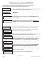
M1 Keypad Programming for the M1XRFTW
From the keypad enter the Installer Level Programming mode. Press ELK, 9 > (enter installer code).
Navigate to the Wireless Setup - Menu 14 and press the RIGHT arrow key to select.
12345678901234567890123456789012123
12345678901234567890123456789012123
12345678901234567890123456789012123
12345678901234567890123456789012123
12345678901234567890123456789012123
12345678901234567890123456789012123
12345678901234567890123456789012123
12345678901234567890123456789012123
12345678901234567890123456789012123
12345678901234567890123456789012123
12345678901234567890123456789012123
There are four (4) wireless setup submenus: 1-Receiver (Transceiver) Options, 2-Xmitter
Options, 3-Xmitter Enroll, and 4-Keyfob Event Definitions. Use the UP or DOWN arrow keys to
locate the desired submenu, then press the right arrow key to select.
14-Wireless
Setup
r
Wireless Submenu
1234567890123456789012345678901212345
1234567890123456789012345678901212345
1234567890123456789012345678901212345
1234567890123456789012345678901212345
1234567890123456789012345678901212345
1234567890123456789012345678901212345
1234567890123456789012345678901212345
1234567890123456789012345678901212345
1234567890123456789012345678901212345
1234567890123456789012345678901212345
1234567890123456789012345678901212345
1234567890123456789012345678901212345
1234567890123456789012345678901212345
1234567890123456789012345678901212345
1234567890123456789012345678901212345
1234567890123456789012345678901212345
1234567890123456789012345678901212345
1234567890123456789012345678901212345
1234567890123456789012345678901212345
1234567890123456789012345678901212345
1234567890123456789012345678901212345
1234567890123456789012345678901212345
1:Rec Selb Prgr
Receiver Options
RO3:=024 Hours r
Reg. Supervision
1234567890123456789012345678901212345
1234567890123456789012345678901212345
1234567890123456789012345678901212345
1234567890123456789012345678901212345
1234567890123456789012345678901212345
1234567890123456789012345678901212345
1234567890123456789012345678901212345
1234567890123456789012345678901212345
1234567890123456789012345678901212345
1234567890123456789012345678901212345
1234567890123456789012345678901212345
RO4:=004 Hours r
Fire Supervision
123456789012345678901234567890121234
123456789012345678901234567890121234
123456789012345678901234567890121234
123456789012345678901234567890121234
123456789012345678901234567890121234
123456789012345678901234567890121234
123456789012345678901234567890121234
123456789012345678901234567890121234
123456789012345678901234567890121234
123456789012345678901234567890121234
123456789012345678901234567890121234
123456789012345678901234567890121234
123456789012345678901234567890121234
123456789012345678901234567890121234
123456789012345678901234567890121234
123456789012345678901234567890121234
123456789012345678901234567890121234
123456789012345678901234567890121234
123456789012345678901234567890121234
123456789012345678901234567890121234
123456789012345678901234567890121234
123456789012345678901234567890121234
123456789012345678901234567890121234
123456789012345678901234567890121234
123456789012345678901234567890121234
123456789012345678901234567890121234
123456789012345678901234567890121234
123456789012345678901234567890121234
123456789012345678901234567890121234
123456789012345678901234567890121234
123456789012345678901234567890121234
123456789012345678901234567890121234
123456789012345678901234567890121234
2:Xmit Sel b Prgr
Transmitter Opt r
WZn017:Sel b Prg r
Wireless Zone
WZn017 01: = No
r
Enable Transmitr
1234567890123456789012345678901212345
1234567890123456789012345678901212345
1234567890123456789012345678901212345
1234567890123456789012345678901212345
1234567890123456789012345678901212345
1234567890123456789012345678901212345
1234567890123456789012345678901212345
1234567890123456789012345678901212345
1234567890123456789012345678901212345
1234567890123456789012345678901212345
1234567890123456789012345678901212345
WZn017 02: = 0
r
Supervision Type
1234567890123456789012345678901212345
1234567890123456789012345678901212345
1234567890123456789012345678901212345
1234567890123456789012345678901212345
1234567890123456789012345678901212345
1234567890123456789012345678901212345
1234567890123456789012345678901212345
1234567890123456789012345678901212345
1234567890123456789012345678901212345
1234567890123456789012345678901212345
1234567890123456789012345678901212345
WZn017 03: = No
Enable Option 1
Sets the expiration timeout value for supervision of zones assigned as Supervisory Type 2
(Fire Zones). The range is 001 to 255 and the default is 004 hours. Should a Type 2 sensor
fail to check-in prior to this timeout it will be declared missing.
This submenu is for specific transmitter (sensor) options. To select this menu press the
RIGHT arrow key, or press the Up or Down arrow keys to scroll to another submenu.
Use the UP and DOWN arrow keys to locate a particular wireless transmitter. Press the
RIGHT arrow key to select and program the displayed transmitter.
Displays if a transmitter is enabled or disabled. This option CANNOT be used to add a new
device, but it can be used to temporarily suspend or remove an already enrolled device. When
a new sensor is added via the enroll process this location will be set to Yes.
This sets the expected check-in (supervision) interval of a sensor. Burglar (non-fire) sensors
should be set as "1"=Normal Supervision. Fire Sensors should be set as "3" = Fire
Supervision. CAUTION! Keychain Remotes (Fobs) or sensors that leave the building MUST
be set to "0" = non supervised. See receiver selections R02 and R03 for supervision time
values. Valid values are: 0, 1, or 3
Factory default setting is 1 (Normal Supervision).
This is relevant to a few select sensors. Factory default is No. See the List of Elk 6000
This is relevant to a few select sensors. Factory default is No. See the List of Elk 6000
r Series Wireless Sensors to determine which transmitters use this option.
1234567890123456789012345678901212345
1234567890123456789012345678901212345
1234567890123456789012345678901212345
1234567890123456789012345678901212345
1234567890123456789012345678901212345
1234567890123456789012345678901212345
1234567890123456789012345678901212345
1234567890123456789012345678901212345
1234567890123456789012345678901212345
1234567890123456789012345678901212345
WZn017 05: = 001
Keyfob User ID
Sets the expiration timeout value for supervision of zones assigned as Supervisory Type 1
(Non-Fire Zones). The range is 001 to 255 hours and the default is 024 hours. If a Type 1
sensor fails to check-in prior to this timeout it will be declared missing. The Type is assigned
to each transmitter (sensor) under Transmitter Opt 02 (see below).
r Series Wireless Sensors to determine which transmitters use this option.
1234567890123456789012345678901212345
1234567890123456789012345678901212345
1234567890123456789012345678901212345
1234567890123456789012345678901212345
1234567890123456789012345678901212345
1234567890123456789012345678901212345
1234567890123456789012345678901212345
1234567890123456789012345678901212345
1234567890123456789012345678901212345
1234567890123456789012345678901212345
1234567890123456789012345678901212345
WZn017 04: = No
Enable Option 2
Description
This submenu is for Receiver (Transceiver) options. To select this menu press the RIGHT
arrow key, or press the Up or Down arrow keys to scroll the submenus.
r
123456789012345678901234567890121234
123456789012345678901234567890121234
123456789012345678901234567890121234
123456789012345678901234567890121234
123456789012345678901234567890121234
123456789012345678901234567890121234
123456789012345678901234567890121234
123456789012345678901234567890121234
123456789012345678901234567890121234
123456789012345678901234567890121234
123456789012345678901234567890121234
WZn017 06: = No
r
PIR Auto Restore
This location allows a number to be assigned as the User ID that will appear in the M1 event
log whenever a Keychain Remote is used to arm/disarm. Valid range is 001 to 255. NOTE:
Standard M1 User codes are 001 to 199.
This option (PIR Auto Restore) is not currently used by the M1XRFTW.
WZn017 shown as an example only!
† Not evaluated by UL
Page 10
M1XRFTW Installation Manual
123456789012345678901234567890121234
123456789012345678901234567890121234
123456789012345678901234567890121234
123456789012345678901234567890121234
123456789012345678901234567890121234
123456789012345678901234567890121234
123456789012345678901234567890121234
123456789012345678901234567890121234
123456789012345678901234567890121234
123456789012345678901234567890121234
123456789012345678901234567890121234
3:Learn Selb Prgr
WirelessTransmtr
3a
123456789012345678901234567890121234
123456789012345678901234567890121234
123456789012345678901234567890121234
123456789012345678901234567890121234
123456789012345678901234567890121234
123456789012345678901234567890121234
123456789012345678901234567890121234
123456789012345678901234567890121234
123456789012345678901234567890121234
123456789012345678901234567890121234
123456789012345678901234567890121234
123456789012345678901234567890121234
3b
12345678901234567890123456789012123
12345678901234567890123456789012123
12345678901234567890123456789012123
12345678901234567890123456789012123
12345678901234567890123456789012123
12345678901234567890123456789012123
12345678901234567890123456789012123
12345678901234567890123456789012123
12345678901234567890123456789012123
12345678901234567890123456789012123
12345678901234567890123456789012123
WZone = 017 HW l
TransmitrToLrn r
This submenu is used to manually enroll transmitters (sensors). To select this menu press
the RIGHT arrow key, or press the Up or Down arrow keys to scroll submenus.
Select the zone for the new transmitter (sensor) by entering the three (3) digit zone number
OR by scrolling to the zone number using the UP and DOWN arrow keys. NOTE: If a transmitter is already enrolled for this zone the display will resemble 3c below. Otherwise, it will
display "TransmitrToLrn".
WZone = 17 shown as example
Press the RIGHT arrow key to select and program the zone.
3c
WZone = xxx Push
TransmiterButton
As this message is displayed the M1 will speak: "Press Transmitter Button for Zone XXX". Go
to the transmitter (sensor) and execute the enroll process according the sensor instructions.
In most cases this requires inserting the battery. If successful the keypad will chime and M1
will speak: "[Zone Number/Name] Enrollment." Refer to step 3c below.
12345678901234567890123456789012123
12345678901234567890123456789012123
12345678901234567890123456789012123
12345678901234567890123456789012123
12345678901234567890123456789012123
12345678901234567890123456789012123
12345678901234567890123456789012123
12345678901234567890123456789012123
12345678901234567890123456789012123
12345678901234567890123456789012123
12345678901234567890123456789012123
12345678901234567890123456789012123
The TXID of the newly enrolled transmitter (sensor) will momentarily display. Rapid Enroll will
then auto-advance to the next zone (step 3b) to permit sequential enrollment of transmitters.
Press the ELK key twice to exit the enrollment after all new sensors have been enrolled.
WZone = xxx
Enrolled ABCDE1
DELETING A WIRELESS SENSOR - To delete an existing sensor navigate to option "WZnxxx
01" and select "No". NOTE: Manually setting the Loop to 0 will also delete a sensor.
3d
123456789012345678901234567890121234
123456789012345678901234567890121234
123456789012345678901234567890121234
123456789012345678901234567890121234
123456789012345678901234567890121234
123456789012345678901234567890121234
123456789012345678901234567890121234
123456789012345678901234567890121234
123456789012345678901234567890121234
123456789012345678901234567890121234
123456789012345678901234567890121234
WZone = xxx HW l
A0000000 Loop=0
1234567890123456789012345678901212345
1234567890123456789012345678901212345
1234567890123456789012345678901212345
1234567890123456789012345678901212345
1234567890123456789012345678901212345
1234567890123456789012345678901212345
1234567890123456789012345678901212345
1234567890123456789012345678901212345
1234567890123456789012345678901212345
1234567890123456789012345678901212345
1234567890123456789012345678901212345
123456789012345678901234567890121234
123456789012345678901234567890121234
123456789012345678901234567890121234
123456789012345678901234567890121234
123456789012345678901234567890121234
123456789012345678901234567890121234
123456789012345678901234567890121234
123456789012345678901234567890121234
123456789012345678901234567890121234
123456789012345678901234567890121234
123456789012345678901234567890121234
123456789012345678901234567890121234
123456789012345678901234567890121234
123456789012345678901234567890121234
123456789012345678901234567890121234
123456789012345678901234567890121234
123456789012345678901234567890121234
123456789012345678901234567890121234
123456789012345678901234567890121234
123456789012345678901234567890121234
123456789012345678901234567890121234
123456789012345678901234567890121234
123456789012345678901234567890121234
123456789012345678901234567890121234
123456789012345678901234567890121234
123456789012345678901234567890121234
123456789012345678901234567890121234
123456789012345678901234567890121234
123456789012345678901234567890121234
123456789012345678901234567890121234
123456789012345678901234567890121234
123456789012345678901234567890121234
123456789012345678901234567890121234
123456789012345678901234567890121234
123456789012345678901234567890121234
123456789012345678901234567890121234
123456789012345678901234567890121234
123456789012345678901234567890121234
123456789012345678901234567890121234
123456789012345678901234567890121234
123456789012345678901234567890121234
123456789012345678901234567890121234
123456789012345678901234567890121234
123456789012345678901234567890121234
123456789012345678901234567890121234
123456789012345678901234567890121234
123456789012345678901234567890121234
123456789012345678901234567890121234
123456789012345678901234567890121234
123456789012345678901234567890121234
123456789012345678901234567890121234
123456789012345678901234567890121234
123456789012345678901234567890121234
123456789012345678901234567890121234
123456789012345678901234567890121234
123456789012345678901234567890121234
123456789012345678901234567890121234
123456789012345678901234567890121234
123456789012345678901234567890121234
123456789012345678901234567890121234
123456789012345678901234567890121234
123456789012345678901234567890121234
123456789012345678901234567890121234
123456789012345678901234567890121234
123456789012345678901234567890121234
123456789012345678901234567890121234
123456789012345678901234567890121234
123456789012345678901234567890121234
123456789012345678901234567890121234
123456789012345678901234567890121234
123456789012345678901234567890121234
123456789012345678901234567890121234
123456789012345678901234567890121234
123456789012345678901234567890121234
123456789012345678901234567890121234
123456789012345678901234567890121234
123456789012345678901234567890121234
123456789012345678901234567890121234
123456789012345678901234567890121234
123456789012345678901234567890121234
123456789012345678901234567890121234
123456789012345678901234567890121234
123456789012345678901234567890121234
123456789012345678901234567890121234
123456789012345678901234567890121234
123456789012345678901234567890121234
123456789012345678901234567890121234
123456789012345678901234567890121234
123456789012345678901234567890121234
123456789012345678901234567890121234
123456789012345678901234567890121234
123456789012345678901234567890121234
123456789012345678901234567890121234
123456789012345678901234567890121234
123456789012345678901234567890121234
4:KeyfobSelb Prgr
Event Definition
SETTING THE LOOP #. For Keychain remotes the Loop # does not matter! - For single zone
sensors like the ELK-6020 and 6021 the Loop # should be 2 but the M1 factory default Loop
# 0 will also recognize the built-in reed switch without having to change (program) the Loop
from 0 to 2. - For multi-zone sensors like the ELK-6022 the Loop # is VERY IMPORTANT!
From step 3a press the Keypad LEFT arrow marked "HW". The TXID in decimal notation will
display on the lower left. Press the RIGHT arrow to move the cursor over to Loop =. Enter 1,
2, or 3 according to the sensor instructions. Refer to the "Elk 6000 Series Wireless Sensors"
for more information.
This submenu is used to program the operation or "action" for Keychain Remote (FOB)
buttons. Each button can be assigned one of six (6) separate operations as explained
below. To select this menu press the RIGHT arrow key.
Key=1 Evt=0000r
[name of event]
Press the UP or DOWN arrow keys to select a key (button) 1 to 8. Some Keychain Remote
models may not support all the programmable buttons. The event or operation for each
button is set by a four (4) digit event code. The range of event codes is 0000 to 0030 See
M1 Installer Manual, Appendix A, Event Codes.
Key=2 Evt=0000r
[name of event]
Factory default = Only keys (buttons) 1 and 2 have a default setting.
Key=3 Evt=0000r
[name of event]
Key=4 Evt=0000r
[name of event]
Key=5 Evt=0000r
[name of event]
Key=6 Evt=0000r
[name of event]
Key=7 Evt=0000r
[name of event]
Key=8 Evt=0000r
[name of event]
M1XRFTW Installation Manual
Key (Button) & Symbol
Key1 - Lock
Key2 - Unlock
Key3 - i Status Inquiry
Key4 - Red Triangle
M1 Factory Default Event & Operation
Event=0027 - KeyMomAway (Arm the Control)
Event=0029 - KeyMomDisarm (Disarm the Control)
Event=0000 - unprogrammed See NOTE 1 below
Event=0000 - unprogrammed See NOTE 2 below
NOTE 1: Key (button) 3 on a 6010 Keychain Remote ALWAYS performs a system status
Inquiry when pressed momentarily. This same key may be pressed and held for four (4)
seconds to activate M1 programmable Key3 event. Factory default is 0000 (do nothing)
NOTE 2: Key (button) 4 on a 6010 Keychain Remote REQUIRES a press and hold for two (2)
full seconds in order to activate M1 programmable Key4 event. This can be any event,
however the most common use is for emergency panic (Police Panic event 0023 or 0024).
Factory default is 0000 (do nothing)
DOUBLE KEY (BUTTON) PRESSES
M1 programmable Key7 event may be triggered by pressing the top 2 keys (buttons) together
for ~3 seconds, and Key8 event may be triggered by pressing and holding the bottom 2 keys.
SWAPPING THE KEY (BUTTON) FUNCTIONS
The M1 programmable keychain events are GLOBAL for all units. While it is not possible to
fully customize the keys for multiple persons, it is possible to swap keys 1,2,3,4 to become
keys 5,6,7,8. This allows 2 different remotes or people to activate different events. Enable
Option 1 from Menu 14, sub-menu 2:Xmit Transmitter Opt.
Page 11
Appendix A - Data Bus Selection Table
This table should help visualize how the Wireless Zones and Hardwired Zones share the data bus address assignments. Please note that
No Wireless Zones Are Allowed Above Zone 160. This table shows the starting wireless Zone # and data bus address along with the
additional data bus addresses and Zone #’s necessary to obtain the total and best mix of wireless and hardwired zones. The left column
indicates the total maximum wireless zones that may be obtained based on the data bus addresses chosen.
1. The bolded column indicates that the 1st M1XRFTW Transceiver must be at data bus address 2. This also means that the first wireless
zone will be Zone #17.
2. If possible, try to determine how many total wireless zones might ever be needed now or in the future on this installation. And be sure to
also consider the possibility of future hardwired zones and M1XIN hardwired expanders in the future.
NOTE: The total (max.) number of wireless zones will be decreased by 16 zones for any hardwired expanders installed
and enrolled in the data bus addresses at or below Addr 10. The reason is that only zones 17 to 160 can be used for
wireless zones, and data bus addresses 2 thru 10 correspond to zones 17 to 160.
It is strongly recommended that all wireless zones be sequential, with no hardwired zones interspersed between them.
The following are suggested guidelines:
- If there is any possibility that additional wireless zones might be needed in the future, consider leaving a gap of 1 or more data bus
addresses between the M1XRFTW data bus address belonging to the last wireless zone and any M1XIN hardwired zone expanders.
- If there is little or no likelihood of additional wireless zones being required, the 1st hardwired zone expander can be If setup and enrolled
at the first available data bus address right after the last wireless zone
3. Start down the left column and pick the line that represents the maximum number of wireless zones required. Follow this row across
to find the first column indicating “hardwired”. The top of this column shows the data bus address where an M1XIN Hardwired Zone
Expander may be enrolled.
- Up to 3 additional “redundant” M1XRFTW Transceivers may optionally be installed at data bus addresses 3, 4, & 5. Redundant Receivers
may be remotely mounted and wired back to the M1 Control to provide additional range and coverage in extremely large or difficult
buildings. See Appendix C regarding Redundant Receivers.
NOTE: An M1XRFTW installed for redundancy does not increase the number of wireless zones, it only helps to improve
the range and coverage.
No Wireless Zones Here
st
Primary (1 )
M1XRFTW
must be at
Data bus
Addr 2
Zones 17-32
Data Bus
Addr 3
Data Bus
Addr 4
Data Bus
Addr 5
Data Bus
Addr 6
Data Bus
Addr 7
Data Bus
Addr 8
Data Bus
Addr 9
Data Bus
Addr 10
Data Bus
Addr 11
Data Bus
Addr 12
Data Bus
Addr 13
Zones
33 - 48
Zones
49 - 64
Zones
65 - 80
Zones
81 - 96
Zones
97 - 112
Zones
113-128
Zones
129-144
Zones
145-160
Zones
161-176
Zones
177-192
Zones
193-208
16
Optional 2nd
M1XRFTW *
32
**
Optional 3rd
M1XRFTW *
M1XIN
Hardwired
Optional 4th
M1XRFTW *
M1XIN
Hardwired
M1XIN
Hardwired
M1XIN
Hardwired
M1XIN
Hardwired
M1XIN
Hardwired
M1XIN
Hardwired
M1XIN
Hardwired
M1XIN
Hardwired
M1XIN
Hardwired
M1XIN
Hardwired
M1XIN
Hardwired
M1XIN
Hardwired
M1XIN
Hardwired
M1XIN
Hardwired
M1XIN
Hardwired
M1XIN
Hardwired
M1XIN
Hardwired
M1XIN
Hardwired
M1XIN
Hardwired
M1XIN
Hardwired
M1XIN
Hardwired
M1XIN
Hardwired
M1XIN
Hardwired
M1XIN
Hardwired
M1XIN
Hardwired
M1XIN
Hardwired
M1XIN
Hardwired
M1XIN
Hardwired
M1XIN
Hardwired
M1XIN
Hardwired
M1XIN
Hardwired
M1XIN
Hardwired
M1XIN
Hardwired
M1XIN
Hardwired
M1XIN
Hardwired
M1XIN
Hardwired
M1XIN
Hardwired
M1XIN
Hardwired
M1XIN
Hardwired
M1XIN
Hardwired
M1XIN
Hardwired
M1XIN
Hardwired
M1XIN
Hardwired
M1XIN
Hardwired
M1XIN
Hardwired
M1XIN
Hardwired
M1XIN
Hardwired
M1XIN
Hardwired
M1XIN
Hardwired
M1XIN
Hardwired
M1XIN
Hardwired
M1XIN
Hardwired
M1XIN
Hardwired
M1XIN
Hardwired
M1XIN
Hardwired
M1XIN
Hardwired
M1XIN
Hardwired
M1XIN
Hardwired
M1XIN
Hardwired
Total
Wireless
Zones
(max.)
48
**
**
**
**
**
**
**
**
**
**
**
**
**
**
112
**
**
**
**
**
**
128
**
**
**
**
**
**
**
144
**
**
**
**
**
**
**
M1XRFTW
64
80
96
A single
M1XRFTW can
add up to 144
wireless zones to
the M1 Control.
**
* indicates an Address where either a redundant M1XRFTW Wireless Transceiver OR a M1XIN Hardwired Expander can be installed.
* * indicates a Reserved Address which can ONLY be used for wireless zones based on the total number of desired wireless zones.
Fundamentally only 1 M1XRFTW Wireless Transceiver is needed to add 144 wireless zones to an M1 or M1EZ8 Control. But
this presumes that each wireless sensor is installed within the coverage range of the single transceiver. In large buildings or
where all sensors cannot be covered by a single M1XRFTW transceiver then up to 3 additional M1XRFTWs may be connected to
the data bus and deployed into the more distant areas. IMPORTANT! If additional M1XRFTWs are installed they MUST be set
and enrolled ONLY at data bus addresses 3, 4, and 5.
Page 12
M1XRFTW Installation Manual
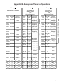
Appendix B - Examples of Zone Configurations
Example A
Example B
Example C
All 208 Zones as Hardwired
144 M1XRFTW
Wireless Zones
plus
16 Hardwired Zones
112 M1XRFTW
Wireless Zones
plus
48 Hardwired Zones
Inputs on
Main Panel
Zones
1-16
Bus Addr
N/A
Inputs on
Main Panel
Zones
1-16
Bus Addr
N/A
Inputs on
Main Panel
Zones
17-32
Bus Addr
2
M1XIN
Zones
17-32
Bus Addr
2
M1XRFTW
Zones
17-32
Bus Addr
2
M1XRFTW
Zones
33-48
Bus Addr
3
M1XIN
Zones
33-48
Bus Addr
3
Optional 2nd
M1XRFTW
Zones
33-48
Bus Addr
3
Optional 2nd
M1XRFTW
Zones
49-64
Bus Addr
4
M1XIN
Zones
49-64
Bus Addr
4
Optional 3rd
M1XRFTW
Zones
49-64
Bus Addr
4
Optional 3rd
M1XRFTW
Zones
65-80
Bus Addr
5
M1XIN
Zones
65-80
Bus Addr
5
Optional 4th
M1XRFTW
Zones
65-80
Bus Addr
5
Optional 4th
M1XRFTW
Zones
81-96
Bus Addr
6
M1XIN
Zones
81-96
Bus Addr
6
Zones
81-96
Bus Addr
6
Zones
97-112
Bus Addr
7
M1XIN
Zones
97-112
Bus Addr
7
Zones
97-112
Bus Addr
7
Zones Bus Addr
113-128
8
M1XIN
Zones Bus Addr
113-128
8
Zones Bus Addr
129-144
9
M1XIN
Zones Bus Addr
129-144
9
Zones Bus Addr
129-144
9
M1XIN
Zones Bus Addr
145-160
10
M1XIN
Zones Bus Addr
145-160
10
Zones Bus Addr
145-160
10
M1XIN
Zones Bus Addr
161-176
11
M1XIN
Zones Bus Addr
161-176
11
M1XIN
Zones Bus Addr
161-176
11
M1XIN
Zones Bus Addr
177-192
12
M1XIN
Zones Bus Addr
177-192
12
M1XIN
Zones Bus Addr
177-192
12
M1XIN
Zones Bus Addr
M1XIN or
193-208
13
Keypad Zones
Absolutely
NO M1XIN
Expanders
on addresses
2 thru 10
Zones Bus Addr
M1XIN or
193-208
13
Keypad Zones
Zones Bus Addr
113-128
8
Absolutely
NO M1XIN
Expanders
on addresses
2 thru 7
Zones Bus Addr
M1XIN or
193-208
13
Keypad Zones
N/A
Bus Addr
14
N/A
N/A
Bus Addr
14
N/A
N/A
Bus Addr
14
N/A
N/A
Bus Addr
15
N/A
N/A
Bus Addr
15
N/A
N/A
Bus Addr
15
N/A
M1XRFTW Installation Manual
Maximum of 112 Wireless Zones
Bus Addr
N/A
Maximum of 144 Wireless Zones
Zones
1-16
Page 13
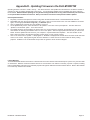
Appendix C - Installing Multiple Redundant M1XRFTW Transceivers
After the first M1XRFTW Transceiver has been installed at address 2, up to 3 additional units may be installed for redundancy or
improved coverage and range. Each addtional unit will require its own data bus address and must be enrolled into the control.
IMPORTANT NOTE: There can be no more than 4 total ELK-M1XRFTW Transceivers connected to the M1
Control.
Shipping
M1XRFTW
Warehouse
M1XRFTW
Production
Sales
Offices
M1XRFTW
M1XRFTW
EXAMPLE OF LARGE COMMERCIAL BUILDING with the maximum of 4 M1XRFTW Transceivers
Page 14
M1XRFTW Installation Manual
Appendix D - Updating Firmware in the ELK-M1XRFTW
Operating firmware is stored in “Flash” memory. This allows electronic field updates and eliminates the old fashion method of
changing IC chips or shipping boards back to the factory. As new firmware updates become available they will be posted on
ELK's website. NOTE: Firmware updating can only be done through the M1 Control using a Direct to PC Com port connection
or an optional Ethernet Network connection. Dial-up connections cannot be used to perform firmware updates.
How to Update Firmware:
1. Physically connect the Computer and Control using either the RS-232 Serial Ports or the M1XEP Ethernet Interface.
3. Start ElkRP and open the account belonging to the control. Click on the Connection menu icon and establish a connection.
Again, use the appropriate Direct using Com_ OR Network options.
4. Click on Update/Verify Firmware from the Send/Rcv menu icon.
5. On the Update/Verify screen, select the device to be updated. In this case it is a Input Expander. Then also select the
“Update to new firmware” option. Then click Continue.
6. The Update Firmware screen displays the device name, the current Firmware, Hardware, and Bootware version, and a pull
down window for selecting the firmware version to use on the update. Select the appropriate firmware that you wish to use.
NOTE: Firmware update files are stored on your computer in a special folder titled "Updates". The exact location of this
folder varies according to the Windows operating system which you are currently running.
7. Click on the check box for “Update”. If “Reprogram” or “Rollback” is displayed the firmware file is the same as OR older that
what is in the control. Reprogramming with the same firmware is a waste of time but was included for factory testing
purposes. Rollback is not recommended except under the guidance of Elk Technical Support.
Limited Warranty
The ELK-M1XRFTW Wireless Transceiver is warranted to be free from defects and workmanship for a period of 2 years from date
of manufacture. Batteries used with wireless devices are not warranted. Elk makes no warranty, express or implied, including
that of mechantability or fitness for any particular purpose with regard to batteries used with wireless devices. Refer to Elk’s website
for full warranty statement and details.
M1XRFTW Installation Manual
Page 15
Page 16
M1XRFTW Installation Manual