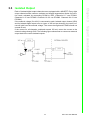
1
User Manual PCL-734 32-channel Isolated Digital Output Card Copyright The documentation and the software included with this product are copyrighted 2008 by Advantech Co., Ltd. All rights are reserved. Advantech Co., Ltd. reserves the right to make improvements in the products described in this manual at any time without notice. No part of this manual may be reproduced, copied, translated or transmitted in any form or by any means without the prior written permission of Advantech Co., Ltd. Information provided in this manual is intended to be accurate and reliable. However, Advantech Co., Ltd. assumes no responsibility for its use, nor for any infringements of the rights of third parties, which may result from its use. Acknowledgements Intel and Pentium are trademarks of Intel Corporation. Microsoft Windows and MS-DOS are registered trademarks of Microsoft Corp. All other product names or trademarks are properties of their respective owners. Product Warranty (2 years) Advantech warrants to you, the original purchaser, that each of its products will be free from defects in materials and workmanship for two years from the date of purchase. This warranty does not apply to any products which have been repaired or altered by persons other than repair personnel authorized by Advantech, or which have been subject to misuse, abuse, accident or improper installation. Advantech assumes no liability under the terms of this warranty as a consequence of such events. Because of Advantech’s high quality-control standards and rigorous testing, most of our customers never need to use our repair service. If an Advantech product is defective, it will be repaired or replaced at no charge during the warranty period. For outof-warranty repairs, you will be billed according to the cost of replacement materials, service time and freight. Please consult your dealer for more details. If you think you have a defective product, follow these steps: 1. Collect all the information about the problem encountered. (For example, CPU speed, Advantech products used, other hardware and software used, etc.) Note anything abnormal and list any onscreen messages you get when the problem occurs. 2. Call your dealer and describe the problem. Please have your manual, product, and any helpful information readily available. 3. If your product is diagnosed as defective, obtain an RMA (return merchandize authorization) number from your dealer. This allows us to process your return more quickly. 4. Carefully pack the defective product, a fully-completed Repair and Replacement Order Card and a photocopy proof of purchase date (such as your sales receipt) in a shippable container. A product returned without proof of the purchase date is not eligible for warranty service. 5. Write the RMA number visibly on the outside of the package and ship it prepaid to your dealer. Part Number: 2003734000 Edition 1 Printed in Taiwan PCL-734 User Manual March 2012 ii Declaration of Conformity CE This product has passed the CE test for environmental specifications when shielded cables are used for external wiring. We recommend the use of shielded cables. This kind of cable is available from Advantech. Please contact your local supplier for ordering information. CE This product has passed the CE test for environmental specifications. Test conditions for passing included the equipment being operated within an industrial enclosure. In order to protect the product from being damaged by ESD (Electrostatic Discharge) and EMI leakage, we strongly recommend the use of CE-compliant industrial enclosure products. FCC Class B Note: This equipment has been tested and found to comply with the limits for a Class B digital device, pursuant to part 15 of the FCC Rules. These limits are designed to provide reasonable protection against harmful interference in a residential installation. This equipment generates, uses and can radiate radio frequency energy and, if not installed and used in accordance with the instructions, may cause harmful interference to radio communications. However, there is no guarantee that interference will not occur in a particular installation. If this equipment does cause harmful interference to radio or television reception, which can be determined by turning the equipment off and on, the user is encouraged to try to correct the interference by one or more of the following measures: Reorient or relocate the receiving antenna. Increase the separation between the equipment and receiver. Connect the equipment into an outlet on a circuit different from that to which the receiver is connected. Consult the dealer or an experienced radio/TV technician for help. Technical Support and Assistance 1. 2. Visit the Advantech web site at www.advantech.com/support where you can find the latest information about the product. Contact your distributor, sales representative, or Advantech's customer service center for technical support if you need additional assistance. Please have the following information ready before you call: – Product name and serial number – Description of your peripheral attachments – Description of your software (operating system, version, application software, etc.) – A complete description of the problem – The exact wording of any error messages iii PCL-734 User Manual Warnings, Cautions and Notes Warning! Warnings indicate conditions, which if not observed, can cause personal injury! Caution! Cautions are included to help you avoid damaging hardware or losing data. e.g. There is a danger of a new battery exploding if it is incorrectly installed. Do not attempt to recharge, force open, or heat the battery. Replace the battery only with the same or equivalent type recommended by the manufacturer. Discard used batteries according to the manufacturer's instructions. Document Feedback To assist us in making improvements to this manual, we would welcome comments and constructive criticism. Please send all such - in writing to: [email protected] Safety Instructions 1. 2. 3. 4. 5. 6. 7. 8. 9. 10. 11. 12. 13. 14. 15. 16. 17. Read these safety instructions carefully. Keep this User Manual for later reference. Disconnect this equipment from any AC outlet before cleaning. Use a damp cloth. Do not use liquid or spray detergents for cleaning. For plug-in equipment, the power outlet socket must be located near the equipment and must be easily accessible. Keep this equipment away from humidity. Put this equipment on a reliable surface during installation. Dropping it or letting it fall may cause damage. The openings on the enclosure are for air convection. Protect the equipment from overheating. DO NOT COVER THE OPENINGS. Make sure the voltage of the power source is correct before connecting the equipment to the power outlet. Position the power cord so that people cannot step on it. Do not place anything over the power cord. All cautions and warnings on the equipment should be noted. If the equipment is not used for a long time, disconnect it from the power source to avoid damage by transient overvoltage. Never pour any liquid into an opening. This may cause fire or electrical shock. Never open the equipment. For safety reasons, the equipment should be opened only by qualified service personnel. If one of the following situations arises, get the equipment checked by service personnel: The power cord or plug is damaged. Liquid has penetrated into the equipment. The equipment has been exposed to moisture. PCL-734 User Manual iv 18. The equipment does not work well, or you cannot get it to work according to the user's manual. 19. The equipment has been dropped and damaged. 20. The equipment has obvious signs of breakage. 21. DO NOT LEAVE THIS EQUIPMENT IN AN ENVIRONMENT WHERE THE STORAGE TEMPERATURE MAY GO BELOW -20° C (-4° F) OR ABOVE 60° C (140° F). THIS COULD DAMAGE THE EQUIPMENT. THE EQUIPMENT SHOULD BE IN A CONTROLLED ENVIRONMENT. 22. CAUTION: DANGER OF EXPLOSION IF BATTERY IS INCORRECTLY REPLACED. REPLACE ONLY WITH THE SAME OR EQUIVALENT TYPE RECOMMENDED BY THE MANUFACTURER, DISCARD USED BATTERIES ACCORDING TO THE MANUFACTURER'S INSTRUCTIONS. 23. The sound pressure level at the operator's position according to IEC 704-1:1982 is no more than 70 dB (A). Safety Precaution - Static Electricity DISCLAIMER: This set of instructions is given according to IEC 704-1. Advantech disclaims all responsibility for the accuracy of any statements contained herein.Safety Precaution - Static Electricity Follow these simple precautions to protect yourself from harm and the products from damage. To avoid electrical shock, always disconnect the power from your PC chassis before you work on it. Don't touch any components on the CPU card or other cards while the PC is on. Disconnect power before making any configuration changes. The sudden rush of power as you connect a jumper or install a card may damage sensitive electronic components. v PCL-734 User Manual PCL-734 User Manual vi Contents Chapter 1 Overview...............................................1 1.1 1.2 1.3 1.4 1.5 Introduction ............................................................................................... 2 Features .................................................................................................... 2 Applications............................................................................................... 2 Specifications ............................................................................................ 3 Daughterboards ........................................................................................ 3 2 Hardware Installation ..........................5 2.1 2.2 2.3 2.4 2.5 Installation ................................................................................................. 6 Initial Inspection ........................................................................................ 6 Switch and Jumper Settings...................................................................... 7 Table 2.1: Connectors, Jumpers, and Switches .......................... 7 Base Address selection (SW1) ................................................................. 8 Hardware Installation ............................................................................... 9 3 Signal Connections ...........................11 3.1 3.2 3.3 Overview ................................................................................................. 12 Connector Pin Assignments.................................................................... 12 Isolated Output........................................................................................ 13 Appendix A Register Format .................................15 A.1 Register Format ...................................................................................... 16 Table A.1: Register Assignment ................................................ 16 Appendix B PC I/O Port Address Map ..................17 B.1 PC I/O Port Address Map........................................................................ 18 Chapter Chapter vii PCL-734 User Manual PCL-734 User Manual viii Chapter 1 Overview 1 1.1 Introduction The PCL-734 offers 32 isolated digital output channels on a PC add-on card. Its isolated output channels provide 2,500VDC of protection. Each I/O channel corresponds to a bit in a PC I/O port. This makes the PCL-734 very easy to program. 1.2 Features 32 isolated digital output channels High output driving capacity High-voltage isolation on isolated output channels (2,500VDC) Open collector outputs (up to 40VDC) D-type connectors for isolated output channels High sink current on isolated output channels (200 mA/channel) Suppression diode for inductive loads 1.3 Applications Industrial ON/OFF control Contact closure monitoring Switch status sensing BCD interfacing Digital I/O control Industrial and lab automation PCL-734 User Manual 2 Chapter 1 1.4 Specifications Digital output 32 optically-isolated outputs Output voltage: Open collector 5 to 40 VDC Sink current: 200 mA max. Isolation voltage: 2500 VDC Overview Register format BASE+0 Isolated DO0~DO7 BASE+1 Isolated DO8~DO15 BASE+2 Isolated DO16~DO23 BASE+3 Isolated DO24~DO31 Dimensions 185 mm x 100 mm Connectors DB-37 connector for isolated Digital Output Power consumption +5 V: 330 mA typical, 500 mA maximum +12V: 80 mA typical, 105 mA maximum 1.5 Daughterboards PCLD-880 The PCLD-880 is a universal screw terminal board for industrial wiring. It can be used with the analog or digital ports of various PCLabCards via 20-pin flat cables or shielded round cables with DB-37 connectors. 3 PCL-734 User Manual PCL-734 User Manual 4 Chapter 2 2 Hardware Installation 2.1 Installation This chapter gives users a package item checklist, proper instructions about unpacking and step-by-step procedures for both driver and card installation. 2.2 Initial Inspection We carefully inspected the PCL-734 both mechanically and electrically before shipment. It should be free of marks and in perfect order on receipt. As you unpack the PCL-734, check it for signs of shipping damage (damaged box, scratches, dents, etc.). If it is damaged or fails to meet specifications, notify our service department or your local sales representative immediately. Also, call the carrier immediately and retain the shipping carton and packing material for inspection by the carrier. We will then make arrangements to repair or replace the unit. Discharge any static electricity on your body before you touch the board by touching the back of the system unit (grounded metal). Remove the PCL-734 card from its protective packaging by grasping the rear metal panel. Handle the card only by its edges to avoid static electric discharge which could damage its integrated circuits. Keep the antistatic package. Whenever you remove the card from the PC, please store the card in this package for protection. You should also avoid contact with materials that hold static electricity such as plastic, vinyl and styrofoam. PCL-734 User Manual 6 The PCL-734 card has one function switch and three jumper settings. The following sections tell how to configure the card. You may want to refer to the opposite page for help identifying card components. Chapter 2 2.3 Switch and Jumper Settings Hardware Installation Table 2.1: Connectors, Jumpers, and Switches Label CN1 CN2 SW1 Function Isolated output E.GND (external ground) Card base address 7 PCL-734 User Manual 2.4 Base Address selection (SW1) You control the PCL-734's operation by reading or writing data to the PC's I/O (input/ output) port addresses. The PCL-734 requires four consecutive address locations. Switch SW1 sets the card's base (beginning) address. Valid base addresses range from Hex 200 to Hex 3F0. Other devices in your system may, however, be using some of these addresses. We set the PCL-734 for a base address of Hex 300 at the factory. If you need to adjust it to some other address range, set switch SW1 as shown in the following table: Note: Switches 1-8 control the PC bus address lines as shown below: Switch Line 1 A9 PCL-734 User Manual 2 A8 3 A7 4 A6 5 A5 6 A4 8 7 A3 8 A2 Warning! TURN OFF your PC power supply whenever you install or remove the PCL-734 or connect and disconnect cables. 1. 4. 5. 6. 7. 8. 9. 9 PCL-734 User Manual Hardware Installation 2. 3. Turn the computer off. Turn the power off to any peripheral devices such as printers and monitors. Disconnect the power cord and any other cables from the back of the computer. Remove the system unit cover (refer to your user's guide chassis user's guide if necessary). Locate the expansion slots at the rear of the unit and choose any unused slot. Remove the screw that secures the expansion slot cover to the system unit. Save the screw to secure the interface card retaining bracket. Carefully grasp the upper edge of the PCL-734 card. Align the hole in the retaining bracket with the hole on top of the expansion slot and align the gold striped edge connector with the expansion slot socket. Press the board firmly into the socket. Secure the PCL-734 using the screw you removed in step 5. Attach any accessories (i.e. a DB-37 cable, etc.) to the PCL-734. Replace the system unit cover. Connect the cables you removed in step 2. Turn the computer power on. Chapter 2 2.5 Hardware Installation PCL-734 User Manual 10 Chapter 3 3 Signal Connections 3.1 Overview Maintaining signal connections is one of the most important factors in ensuring that your application system is sending and receiving data correctly. A good signal connection can avoid unnecessary and costly damage to your PC and other hardware devices. This chapter provides useful information about how to connect input and output signals to the PCL-734 via the I/O connector. 3.2 Connector Pin Assignments The PCL-734 has a DB-37 connector accessible from the card bracket. See the figure on page 9 for the location of each connector. Pin assignments for each connector appear in the following sections. Abbreviations IDO PCL-734 User Manual Isolated Digital Output E.GND External ground for isolated output PCOM Free wheeling diode common 12 13 PCL-734 User Manual Signal Connections Each of isolated digital output channels come equipped with a MOSFET. Every eight output channels share common emitters and integral suppression diodes for inductive loads. activated by connecting PCOM to VDD. (Channels 0~7 use PCOM1. Channels 8~15 use PCOM2. Channels 16~23 use PCOM3. Channels 24~31 use PCOM4.) If the external voltage (5 to 40V) is connected to each isolated output channel (IDO) and its isolated digital output turns on (max. of 200 mA per channel), the card's current will sink from the external voltage. The current through each E.GND should not exceed 50 mA. If the current for all channels combined exceed 150 mA, return the current to the external voltage through CN2. The following figure shows how to connect an external output load to the card's isolated outputs. Chapter 3 3.3 Isolated Output PCL-734 User Manual 14 Appendix A Register Format A A.1 Register Format Programming the PCL-734 is extremely simple. Each output channel corresponds to a bit in the card's registers. To turn on an output channel you write a ‘‘1” to the corresponding bit. The card requires four I/O register addresses. The address of each register is specified as an offset from the card's base address. For example, BASE+0 is the card's base address and BASE+2 is the base address + two bytes. If the card's base address is 300h, the register's address is 302h. See Chapter 2 for information on setting the card's base address. Register assignments are as follows: Table A.1: Register Assignment Address Write Read BASE + 0 IDO bits 0-7 N/A BASE + 1 IDO bits 8-15 N/A BASE + 2 IDO bits 16-23 N/A BASE + 3 IDO bits 24-31 N/A PCL-734 User Manual 16 Appendix B B PC I/O Port Address Map B.1 PC I/O Port Address Map Range (hex) Function 000-1FF Base System 200 Reserved 201 Came Control 202-277 Reserved 278-27F Second Printer Port 280-2F7 Reserved 2F8-2FF COM 2 300-377 Reserved 3713-37F First Printer Port 380-3AF Reserved 3B0-3BF Mono Display/Print Adapter 3C0-3CF Reserved 3D0-3DF Color/Graphics 3E0-3EF Reserved 3F0-3F7 Floppy Disk Drive 3F8-3FF COM 1 PCL-734 User Manual 18 Appendix B PC I/O Port Address Map PCI-1730/1733/1734 User Manual 19 www.advantech.com Please verify specifications before quoting. This guide is intended for reference purposes only. All product specifications are subject to change without notice. No part of this publication may be reproduced in any form or by any means, electronic, photocopying, recording or otherwise, without prior written permission of the publisher. All brand and product names are trademarks or registered trademarks of their respective companies. © Advantech Co., Ltd. 2011