1
'HYHORSHU¶V5HIHUHQFH0DQXDO
PC Card
Wireless LAN Adapter
TM
TM
PC4500/PC4800
PC Card Wireless LAN Adapter
Developer’s Reference Manual
No part of this document may be reproduced or transmitted in any form or by any means, electronic or mechanical, for
any purpose, without the express written permission of Aironet Wireless Communications. Information in this
document is subject to change without notice. Aironet Wireless Communications makes no representations or
warranties with respect to the contents or use of this manual and specifically disclaims any express or implied
warranties of merchantability or fitness for any particular purpose.
© 1999, 1998, 1997 Aironet Wireless Communications. All rights reserved.
Aironet, ARLAN are registered trademarks of Aironet Wireless Communications, Inc.
LM3000™, PC3000™, PC3500™, PC4500™ and PC4800™ are trademarks of Aironet Wireless
Communications, Inc.
All names and product names used in this manual are trademarks or registered tradenames of their
respective companies.
Printed in USA
DOC 710-004247, Revision B1
Contents
PART 1
INTRODUCTION
About the Developer’s Reference Manual ……………………………………...
Typographical Conventions
………………………………………………………..
Reference Documents ……………………………………………………………
Welcome to the PC4500/4800 ……………………………………………………
System Configurations ………………………………………………………………...
Coverage Options …………………………………………………………………….
vii
ix
x
1-1
1-2
1-2
PART 2
GETTING STARTED
Hardware Architecture ………………………………………………………….
System Overview
…………………………………………………………………….
Hardware Overview …………………………………………………………………..
Software Overview ……………………………………………………………………
Protocol Overview
……………………………………………………………………
Overview of the 802.11 Wireless LAN Protocol ………………………………..
Architecture Overview ………………………………………………………………...
802.11 Direct Sequence Frame Format
………………………………………………..
Basic Station Operation ………………………………………………………………..
Authentication and Key Management ……………………………………………………
2-1
2-1
2-2
2-3
2-3
3-1
3-1
3-2
3-5
3-7
PART 3
HARDWARE INTERFACING
PCMCIA Hardware Interface Operation ……………………………………...
PCMCIA Hardware
…………………………………………………………………..
PCMCIA Electrical Connections ………………………………………………………..
ISA Hardware Interface Operation …………………………………………….
ISA Hardware
………………………………………………………………………..
ISA Mode ……………………………………………………………………………
Serial Hardware Interface Operation …………………………………………..
Serial Hardware ………………………………………………………………………
Serial Mode ………………………………………………………………………….
4-1
4-1
4-2
5-1
5-1
5-2
6-1
6-1
6-1
PART 4
SOFTWARE INTERFACING
PCMCIA and ISA Client Software Interface …………………………………..
Host Memory Map ……………………………………………………………………
Host Attribute Memory ……………………………………………………………
Host Common Memory ……………………………………………………………
Host IO Registers ………………………………………………………………...
Recognizing the PC4500/4800 …………………………………………………………
Bootstrap – Starting the PC4500/4800 …………………………………………………..
7-1
7-1
7-1
7-2
7-2
7-4
7-5
Aironet Wireless Communications, Inc.
i
Confidential and Proprietary
Resetting the PC4500/4800 …………………………………………………………….
Interrupt Service Routine (ISR) processing ………………………………………………
Enabling the PC4500/4800 …………...………………………………………………..
Command and Status Register Descriptions ………………………………………………
Command Register ……………………………………………………………...
Param0-2 Registers ………………..…………………………………………….
Status Register …………………………..……………………………………...
Resp0-2 Registers ………………………………………………………………
Event Register Descriptions ………………………………………………………….
EvStat Register
………………………………………………………………...
EvInt Register
…………………...……………………………………………..
EvAck Register …………...……………………………………………………
Basic FID Access ……………….………………………………………………….
FID Management Register Descriptions ………………………………………………..
RxFID Register ………………………………………………………………...
TxAlloc FID Register
…………………………………………………………..
TxComplFID Register …………………………………………………………..
Buffer Access Register Descriptions …………………………………………………..
Select0-1 Registers
…………………………………………………………….
Offset0-1 Registers
…………………………………………………………….
Data0-1 Registers ………………………………………………………………
LinkStat Register
………………………………………………………………
Host Software Register
……………………………………………………………...
SwSupport0-3 Registers
………………………………………………………...
Host Auxiliary Registers …………………………………………………………….
AuxPage Register ………………………………………………………………
AuxOffset Register ……………………………………………………………...
AuxData Register ………………………………………………………………
Command Descriptions ………………………………………………………….…..
NOP Command ………………………………………………………………...
Enable Command ………………………………………………………………
Disable Command ………………………………………………………………
Lose Sync Command ……………………………………………………………
Soft Reset Command ……………………………………………………………
Host Sleep Command ……………………………………………………………
Magic Packet Command ………………………………………………………...
PSP Nodes Command
…………………………………………………………..
Allocate Transmit Buffer Command ………………………………………………
Transmit Command
…………………………………………………………….
Deallocate Command ……………………………………………………………
Access RID Command …………………………………………………………..
Set PHY Register Command
…………………………………………………….
Transmitter Test Command
……………………………………………………...
Error Qualifier Values ………………………………………………………………
Memory (FID/RID) Access ……………….………………………………………….
Reading and Writing RIDs
………………………………………………………
Aironet Wireless Communications, Inc.
ii
7-5
7-6
7-6
7-8
7-12
7-12
7-13
7-13
7-13
7-13
7-15
7-15
7-16
7-16
7-16
7-16
7-17
7-17
7-17
7-17
7-18
7-20
7-21
7-21
7-21
7-21
7-21
7-21
7-22
7-22
7-23
7-24
7-24
7-25
7-25
7-25
7-25
7-25
7-26
7-27
7-27
7-28
7-29
7-31
7-32
7-34
Confidential and Proprietary
Frame Info Descriptor
………………………………………………………………
FID with 802.3 Header – Station Mode
……………………………………………
Receiving an 802.3 Packet ……………………………………….…………...
Transmitting an 802.3 Packet ………………………………………………...
FID without 802.3 Header – Access Point Mode ……………………………………
Receiving an 802.11 Packet
………………………………………………….
Transmitting an 802.11 Packet ………………………………………………..
FID Field Details ………………………………………………………………..
Resource Identifiers ………………………………………………………………...
General Configuration Parameters …………………………………………………….
Station Operation
………………………………………………………………
Access Point Operation ………...………………………………………………..
Wireless LAN Monitor Operation ………………..……………………………….
Packet Header Type ……………..……………………………………………...
Payload Types ………….……………………………………………………...
Aironet Extensions ………….………………………………………………….
Access Point Interface …………..………………………………………………
Receive Mode
………………………………………………………………...
Device Type ……..……………………………………………………………..
802.11 Configuration Parameters ………………..………………………………...
Power Save Operation ………..…………………………………………………
Modulation ………………………………………………………………………...
WEP Key Volatile …………………………………………………………………..
WEP Key Non-Volatile ……………………………………………………………...
Valid SSID List …………………………………………………………………….
Valid AP List ………………………………………………………………………
Driver Name ………………………………………………………………………..
Encapsulation Transformations
………………………………………………………
Capabilities RID ……………………………………………………………….…...
Status RID
………………………………………………………………………...
Radio Information RID
……………………………………………………………...
Access Point RID …………………………………………………………………..
Statistics RID ………………………………………………………………………
Power Save Operation ………………………………………………………………
PLAP Serial Client Software Interface
………………………………………...
Introduction
………………………………………………………………………..
Media Access Control
………………………………………………………………...
Autobaud Sequence
………………………………………………………………
PLAP Synchronization …………………………………………………………….…..
Receiving/Transmitting Frames ………………………………………………………...
PLAP Frame Format
…………………………………………………………….……
Migrating from the LM2000 to the PC4500/4800
………………………………………...
PLAP Commands …………………………………………………………………….
SYNC_REQ ……………………………………………………………………...
SYNC_ACK
…………………………………………………………………….
DATA …………………………………………………………………………..
Aironet Wireless Communications, Inc.
iii
7-35
7-36
7-38
7-39
7-40
7-42
7-43
7-46
7-49
7-50
7-53
7-54
7-54
7-54
7-55
7-55
7-55
7-55
7-55
7-55
7-55
7-56
7-56
7-57
7-57
7-58
7-58
7-59
7-59
7-61
7-61
7-61
7-62
7-66
8-1
8-1
8-1
8-2
8-2
8-2
8-2
8-4
8-4
8-4
8-5
8-5
Confidential and Proprietary
CONFIGURE …………………………………………………………………….
DOWNLOAD …………...……………………………………………………….
HOST_COMMAND …………………………………………………………….
COMMAND_RESPONSE ………………………………………………………
PLAP Boot Strap of PC4500/4800 ………………………………………………...
PART 5
REFERENCE
OEM Radio Approval Information …………………………………..………..
Safety Approvals ………………………………………………………….…………
FCC Approvals ……………………………………………………….…………….
DOC Approvals (Canada) …………………………………………………………….
ETSI Approvals (Europe) …………………………………………………………….
OEM Labeling Requirements ………………………………………………………….
US and US Territories ………………………………..…………………………..
Canada ………………………………………………………………...………..
Europe ………………………………………………………………………….
Other Countries ………………………………….………………………………
AWCSETEE Operation ……………………………..………………………………..
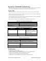
Appendix A – PC4500/4800 Troubleshooting ………………………………...
Indicator LEDs ………………………………………………………………………
Troubleshooting
…………………………………………………………………….
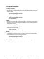
Power Requirements ………………………………………………………………….
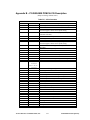
Appendix B – PC4500/4800 PCMCIA CIS Description ……………………...
Appendix C – Reflashing the Firmware on the PC4500/4800 ………………..
Aironet Wireless Communications, Inc.
iv
8-6
8-6
8-10
8-12
8-13
9-1
9-1
9-1
9-2
9-2
9-4
9-4
9-4
9-4
9-4
9-5
A-1
A-1
A-1
A-2
B-1
C-1
Confidential and Proprietary
List of Figures
Figure 1.1 Figure 1.2 Figure 1.3 Figure 2.1 Figure 2.2 Figure 3.1 Figure 3.2 Figure 3.3 Figure 3.4 Figure 8.1 -
Minimal Overlap Coverage Option …………………………………………………
Heavy Overlap Coverage Option ……………………………………………………
Multiple Overlapping Systems Coverage Option …………………………………...
Protocol Model ……………………………………………………………………...
Hardware Block Diagram …………………………………………………………...
Architecture Reference Model ……………………………………………………...
PHY Header Description ……………………………………………………………
MAC Control Information
………………………………………………………….
Relationship Between State Variables and Services ………………………………...
PLAP Packet Format ………………………………………………………………..
Aironet Wireless Communications, Inc.
v
1-3
1-3
1-4
2-2
2-3
3-2
3-3
3-3
3-5
8-3
Confidential and Proprietary
List of Tables
Table A.1 Table A.2 Table A.3 Table A.4 Table B.1 -
Green LED Operating Messages ……………………………………………………
Amber LED Operating Messages
…………………………………………………..
LED Error Codes
…………………………………………………………………...
Power Requirements …………………………………………………………………
CIS Information
…………………………………………………………………….
Aironet Wireless Communications, Inc.
vi
A-1
A-1
A-1
A-2
B-1
Confidential and Proprietary
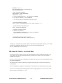
PREFACE
A
About the Developer’s Reference Manual
This guide provides detailed information to aid a developer with both hardware and software interfacing to
the PC4500 and PC4800.
Please consult the User’s Guide & Technical Reference Manual, PC4500/4800 (DOC 710-004239) which
covers installation and maintenance as well configuration with standard operating systems and network
drivers before attempting to install or use the hardware and software described in this guide.
The Developer’s Reference Manual is arranged as follows:
Part 1 - Introduction
Preface - About the Developer’s Reference Manual - introduces the manual, conventions and reference
materials.
Chapter 1 - Welcome to the PC4500/4800 - provides you with a general introduction to the PC4500/4800,
direct sequence spread spectrum radio technology and various configurations you can use when employing
the PC4500/4800 in your radio network.
Part 2 - Getting Started
Chapters in this section provide the information necessary to understand the PC4500/4800 basic theory of
operation.
Chapter 2 - PC4500/4800 Architecture - provides you with an overview of PC4500/4800 architecture.
Chapter 3 - 802.11 Wireless LAN Protocol - provides you with an overview of the 802.11 Wireless LAN
protocol and system tradeoffs.
Part 3 - Hardware Interfacing
Chapters in this section provide detailed hardware integration procedures for installing the PC4500/4800
using its various interfaces.
Aironet Wireless Communications, Inc.
vii
Confidential and Proprietary
Chapter 4 - PCMCIA Interface - contains information necessary when designing a PCMCIA host interface
to the PC4500/4800.
Chapter 5 - ISA Interface - contains information necessary when designing an ISA host interface to the
PC4500/4800.
Chapter 6 - Serial Interface - contains information necessary when designing a serial host interface to the
PC4500/4800.
Part 4 - Software Interfacing
Chapters in this section provide detailed software integration procedures for installing the PC4500/4800
using its various interfaces.
Chapter 7 - PCMCIA and ISA Client Software Interface - contains details for communicating to your
PC4500/4800 using the PCMCIA and ISA interfaces.
Chapter 8 - PLAP Serial Client Software Interface - contains details for communicating to your
PC4500/4800 using the serial interface via the PLAP protocol.
Part 5 –Reference
Appendix A - PC4500/4800 Troubleshooting - explains common problems encountered when integrating
and configuring the PC4500/4800 for operation.
Appendix B - PC4500/4800 PCMCIA CIS Description - explains the PCMCIA configuration required by
the PC4500/4800.
Appendix C - Upgrading Firmware on the PC4500/4800 - explains how to use the Aironet DOS utilities to
upgrade firmware.
Aironet Wireless Communications, Inc.
viii
Confidential and Proprietary
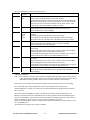
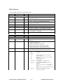
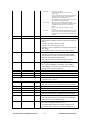
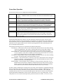
Typographical Conventions
When reading the Developer’s Reference Manual, it is important to understand the symbol and formatting
conventions used in the documentation. The following kinds of symbols and formatting are used in the
guide.
Convention
I
Type of Information
Indicates a note which contains important information set off from
the normal text.
!
A caution message that appears before procedures which if not
observed could result in loss of data or damage to the equipment.
Triangular bullet ➤
Indicates step-by-step procedures.
Bold type
An action you must perform such as type or select.
Monospaced font
Arguments and menus that are visible on the Configuration
Software screens.
“”
Used to emphasize a word or term.
Aironet Wireless Communications, Inc.
ix
Confidential and Proprietary
Reference Documents
Aironet Documents:
“Aironet Antenna Guide”
(document number 710-003725)
“User’s Guide and Technical Reference Manual, PC4500/4800”
(document number 710-004239)
“User’s Guide, AP4500/4800-E/T”
Ethernet and Token Ring versions (document number 710-004240)
“Technical Reference Manual, AP4500/4800-E/T”
Ethernet and Token Ring versions (document number 710-004242)
Third Party Documents:
IEEE Standard 802.11 “Wireless LAN Specification” by IEEE
“PC Card Standard” by the Personal Computer Memory Card Interface Association
IEEE Standard 996 “ISA Specification” by IEEE
“ISA and EISA Theory and Operation” by Edward Solari
ISBN 0-929392-15-9, third edition, 1994
Aironet Wireless Communications, Inc.
x
Confidential and Proprietary
1
INTRODUCTION
A
Welcome to the PC4500/4800
The PC4500 and the PC4800 are radio modules (typically used to create indoor wireless networks and
limited distance outdoor applications) that provide transparent wireless data communications between a
fixed, portable or mobile device and other wireless devices (such as access points connected to a wired
network infrastructure). Host devices can be any device equipped with a PC Card Type II or Type III
slot mechanical form factor. The host interface can be installed to operate as either a PC Card device, as
a serial communications (UART) device, or as an ISA device.
When used in standard network applications, the PC4500/4800 is a direct replacement for a wired
network interface card (NIC). The PC4500/4800 is fully Plug-and-Play compatible when used in host
devices which support the technology.
The PC4500/4800 uses the 2.4GHz direct sequence spread spectrum technology as defined by the IEEE
802.11 Wireless LAN specification in order to accomplish real-time communication between a host
computer or other device on a radio-based local area network. Direct sequence modulation provides
secure, interference-immune communication and does not require a license for operation. The
PC4500/4800 comes standard with Aironet enhancements to the 802.11 protocol which can be enabled to
allow system optimizations which improve throughput and allow for more robust and reliable roaming.
The PC4500 is capable of transmitting and receiving at data rates of 1 and 2 Mbit/s, and the PC4800 can
transmit and receive at data rates of 1, 2, 5.5, and 11 Mbit/s. The adapter can be configured to use either
rate alone or automatically switch between both rates in order to maintain maximum throughput at a
given range. Another advanced feature of the PC4500/4800 is the use of antenna diversity to offer
improved data delivery (higher throughput) as well as extending the usable communication range of the
PC4500/4800. Two antenna connectors are available which allows the connection of two antennas at the
same time. These antennas can be configured as a single unit diversity antenna or two separate remote
antennas. Connecting two antennas (or using the diversity antennas supplied by Aironet) allows the
PC4500/4800 to detect and use the strongest signal coming from either of the antennas to improve
receiver performance. The PC4500/4800 can be configured to use a single antenna for all transmissions
or to choose the antenna offering the best data delivery. In this way, the PC4500/4800 provides you with
the best communication range and reliability for your environment.
In addition to the secure and highly reliable data communication provided by direct sequence spread
spectrum technology, the PC4500/4800 also offers a data encryption option. The encryption method is
referred to as wired equivalent privacy (WEP) and is defined as an optional feature in the 802.11
Aironet Wireless Communications, Inc.
1-1
Confidential and Proprietary
standard. The PC4500/4800 WEP is capable of using 128 bit keys for additional security above the
802.11 standard which specifies the use of 40 bit keys.
System Configurations
The PC4500/4800 can be used in a variety of network system configurations. Aironet access points can
be used to provide a wireless connection to an ethernet or token ring wired network. The PC4500/4800
can be used in any of the following ‘standard’ system architectures:
•
•
•
•
•
•
Point to point wireless connectivity (computer to computer transfer)
Point to multi-point configuration (cash register price updates from server)
Multiple terminal communications (workgroup discussion)
Multiple terminal communication using an access point root unit (conference room discussion)
Wireless mobile infrastructure using access points off a wired LAN (warehouse and retail
environments)
Extended mobile infrastructure using repeaters (temporary parking lot sales)
An all wireless LAN is the simplest LAN configuration. These configurations are also referred to as peer
to peer or ad-hoc networks (802.11 uses the term IBSS – independent basic service set). In an all
Wireless LAN, using a peer to peer network operating system (such as Windows for Workgroups or
Windows 95), all devices equipped with the PC4500/4800 can be linked together and communicate
directly with each other.
Better coordination can be achieved by adding an access point to the configuration. The access point is
not required to be attached to any backbone LAN (such as an Ethernet LAN). It functions as a hub,
linking all workstations and devices together. This configuration is very similar to the peer to peer
network. The main difference is that the access point serves as the focal point for communications,
thereby increasing the effective communication range, since all PC4500/4800 nodes are not required to
be in direct communication range of each other. This configuration offers an added benefit of improved
PC4500/4800 power management for increased battery life and operation of the host device.
A micro-cellular network (infrastructure) can be created by placing two or more access points on a
backbone LAN. The wireless protocols and access point communications facilitate mobility by allowing
remote workstations to move from the domain of one microcell to another. The process is seamless and
transparent, and the connection to the file server or host is maintained without disruption. This
configuration is particularly useful with portable or mobile network workstations allowing these nodes to
maintain a session with an application executing on the wired network, even while moving about
(roaming). When a network is configured using multiple access points and/or repeaters, a mobile client
is automatically connected to the access point, which provides the best performance. This process is
referred to a seamless roaming.
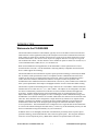
Coverage Options
The system architecture options of the PC4500/4800 client devices and AP4500/4800 access points
provide for a variety of coverage alternatives and flexibility. The system can be designed to provide a
wide coverage area with minimal overlap (Figure 1.1) or coverage with heavy overlap (Figure 1.2) which
can improve system performance and add protection (redundancy) against downtime in the event of an
access point failure.
Aironet Wireless Communications, Inc.
1-2
Confidential and Proprietary
Figure 1.1 - Minimal Overlap Coverage Option
By arranging AP4500/4800 access points such that the overlap in coverage area is minimized, a large
area can be covered with minimal system cost. The total bandwidth available to each mobile client will
depend upon the amount of data each mobile client desires to transfer and the number of clients located
in each cell as well as the data rates used for transmission. Seamless roaming is supported as a mobile
client moves in and out of range of each access point, thereby maintaining a constant connection to the
backbone network. Each access point (and PC4500/4800s) must be configured with the same system
identifier in order to provide the roaming capability.
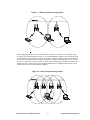
Figure 1.2 - Heavy Overlap Coverage Option
Aironet Wireless Communications, Inc.
1-3
Confidential and Proprietary
By arranging AP4500/4800 access points such that the overlap in coverage area is nearly maximized, a
large number of mobile clients can be supported in the same general coverage area without any
degradation in system performance or connect time. In addition, due to the redundancy in coverage
overlap, system performance is not hampered in the event of an access point failure because clients will
automatically ‘roam’ to an operational access point. With this architecture, all access points and
PC4500\4800s must be configured with the same system identifier. The maximum available bandwidth
will be the sum of that available from each AP4500/4800 with overlapping coverage areas.
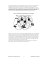
Figure 1.3 - Multiple Overlapping Systems Coverage Option
Multiple systems can operate in the same vicinity by arranging AP4500/4800 access points such that the
overlap in coverage area is as desired. The PC4500/4800-AP4500/4800 architecture provides multiple
channels, which can exist in the same area with virtually no interference to each other. In this mode,
each system must be configured with different system identifiers, which prevents PC4500/4800 clients
from roaming to the access points of a different network. This architecture is useful in circumstances
where different classes of users do not have access to the same network (such as manufacturing and
inventory and design engineering may be on separate networks).
Refer to the User Guide and Technical Reference Manual, PC4500/4800 (DOC 710-004239) for
additional details on these standard architectures and Aironet products.
Aironet Wireless Communications, Inc.
1-4
Confidential and Proprietary
Aironet Wireless Communications, Inc.
1-5
Confidential and Proprietary
P
A
R
T
2
2
CHAPTER 2
A
PC4500/4800 Architecture
This chapter presents the high level design details of the PC4500/4800 and describes some of the features
available from the hardware and software.
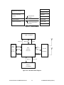
System Overview
The PC4500/4800 can be referred to as an RF modem and is responsible for handling the lowest two
layers (Physical and Data Link) of the OSI protocol reference model. These layers are also referred to as
the PHY (Physical) and MAC (Data Link) layers. The PHY layer is responsible for formatting the data
into a form suitable for delivery as a radio signal. The MAC (media access control) layer is responsible
for formatting the data and timing the delivery of the actual data packet.
Within the MAC layer, functions are divided into two levels. The lower level will handle the data
delivery aspects of the wireless network including packet formatting and RF acknowledgment. The
higher level is responsible for wireless network management. Some of the lower level functions are
performed by hardware but most functionality is determined by software routines executing on a
microcontroller protocol processor.
Executing on the host will typically be NDIS, ODI, or packet drivers which encompass the third and
fourth layers of the OSI model (Network and Transport layers). These device drivers communicate to the
protocol processor via an IO interface and/or interrupts.
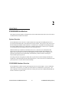
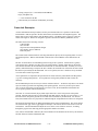
PC4500/4800 Hardware Overview
The PC4500/4800 is a direct sequence spread-spectrum wireless network adapter. It uses a standard PC
card interface, ISA interface, or a UART style serial interface to communicate to a host process. The
main components of the PC4500/4800 architecture are: RF protocol processor, SRAM, Flash ROM, host
interface, and direct sequence radio.
Aironet Wireless Communications, Inc.
2-1
Confidential and Proprietary
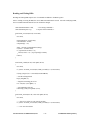
APPLICATION
Application Programs
PRESENTATION
Network Operating
Systems
SESSION
NOS Software
Interface
TRANSPORT
Network Driver
NETWORK
Aironet LAN Cards
Aironet Programmer’s
Interface
DATA LINK
PHYSICAL
Figure 2.1 - Protocol Model
128K x 16 SRAM
SA[16:0]
PCMCIA
ISA
UART
Host
Interface
SD[15:0]
SCTRL
HD[15:0]
HA[9:0]
RXD
MAC
Protocol
Processor
TXD
2.4 GHz
DS Radio
HCTRL
RCTRL
FD[7:0]
FA[17:0]
256K x 8
Flash ROM
Figure 2.2 - Hardware Block Diagram
Aironet Wireless Communications, Inc.
2-2
Confidential and Proprietary
The RF protocol processor is responsible for the low-level protocol functions including the formation of
the packet headers, data scrambling and descrambling, error checking, and packet acknowledgment as
well as the accomplishment of the higher-level MAC functions and RF network management functions.
The 256KB (128Kx16) of SRAM is used for shared memory between the host processor and the
PC4500/4800, buffer storage by the MAC processor, as well as stack, variable, and buffer space required
by the MAC processor.
The 256KB of Flash memory can only be accessed by the MAC processor, and is used for program and
radio calibration data storage.
The PC4500/4800 card has a serial prom containing a unique MAC ID for each card. This address can
be overridden for applications requiring manually configured MAC addresses.
The PC4500/4800 supports three types of host interfaces: a standard PCMCIA interface, an ISA mode
interface, or a UART style serial port.
The PC4500/4800 PCMCIA interface is compliant to the PCMCIA PC Card standard 3.0 electrical and
physical specifications and dynamically responds to 16 bit and 8 bit accesses. This interface provides
access to attribute memory (CIS configuration data) and I/O port (host registers). Access to the MAC
controller registers and shared memory is via I/O addresses, which requires minimum resources from a
host processor. Attribute memory is standardized to even-byte accesses. See Chapter 7 for a description
of the host interface registers.
PC4500/4800 Software Overview
The PC4500/4800 implements a sophisticated wireless data protocol with a direct sequence spreadspectrum physical layer. This protocol is handled transparently to the user. The data delivery interface is
accomplished through a command interface and transmit and receive data buffers.
PCMCIA and ISA operation requires a region of I/O space and an available interrupt. All data transfers
to the PC4500/4800 use I/O reads and writes. Serial operation of the PC4500/4800 requires standard PC
serial port drivers.
A section of memory is available which is arbitrated among the host process and the MAC processes
running on the PC4500/4800. This memory contains the required command and status areas, transmit
and receive buffers, and statistics and configuration information. These memory regions are mapped into
the host’s I/O space (usually via card and socket services) through 32 contiguous 16-bit I/O registers.
PC4500/4800 Protocol Overview
The PC4500/4800 implements a sophisticated wireless data protocol with a direct sequence spreadspectrum physical layer. For detailed information on the protocol, consult the IEEE 802.11 Wireless
LAN specification. Chapter 3 contains an overview of the 802.11 protocol and highlights some
extensions to the protocol provided by Aironet Wireless Communications.
The RF protocol used on the PC4500/4800 is a CSMA/CA (Carrier Sense Multiple Access with Collision
Avoidance) system. This protocol provides a best effort packet delivery service with guaranteed data
integrity by using extensive error checking (16-bit and 32-bit CRCs), length checks, sequence fields,
packet flow control, and low-level packet acknowledgments. Once a directed packet is received by the
PC4500/4800, an acknowledge is immediately sent informing the source that the packet was received
correctly. If a packet is lost due to either a CRC error or a collision in the air with another packet, the
sending station will not get an acknowledgment and the packet will automatically be retransmitted.
Aironet Wireless Communications, Inc.
2-3
Confidential and Proprietary
Upon successful reception of a complete packet, the PC4500/4800 will inform the host processor that it
has a packet in its buffer. Duplicate packets are filtered out via the use of frame sequence numbers in the
header of each frame.
The implemented RF protocol and media access techniques used by the PC4500/4800 cannot be altered
by the programmer. Variations are limited primarily to setting the operating channel(s), maximum
packet size, packet fragmentation size, flow control, and number of packet retries.
The PC4500/4800 can be set to operate in a direct peer-to-peer mode or as part of an infrastructure
network. An infrastructure network consists of Aironet access points that are interconnected via a
distribution system (which may be wireless or wired).
Beyond the point of determining if the PC4500/4800 is associated with an access point, the RF protocol
is transparent to the driver residing on the host. The PC4500/4800 will automatically maintain an
association and attempt to maintain the best link to the distribution system. The driver should monitor
the association status of the PC4500/4800 to be sure that the association has not been lost.
Aironet Wireless Communications, Inc.
2-4
Confidential and Proprietary
3
CHAPTER 3
A
Overview of the 802.11 Wireless LAN Protocol
The IEEE 802.11 Wireless LAN Specification addresses only the lowest two layers of the protocol
model. The main intent is to provide a framework such that multiple vendors can design interoperable
products.
When compared to a wired protocol (like 802.3 for ethernet) which guarantees that all stations can
directly communicate with each other, the uncertain nature of wireless communications does not
guarantee that all users will be able to have direct communications with each other. To overcome this
uncertainty, the 802.11 protocol is based on a MAC scheme known as CSMA/CA (carrier sense multiple
access with collision avoidance). CSMA/CA allows for efficient use of the available bandwidth while
arbitrating between all users.
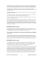
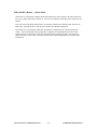
Architecture Overview
Figure 3.1 - Architecture Reference Model
LLC
MAC
MAC
Sublayer
PLCP Sublayer
PHY
MAC Layer
Management
Station
Management
PHY Layer
Management
PMD Sublayer
Aironet Wireless Communications, Inc.
3-1
Confidential and Proprietary
The MAC entity provides the basic access mechanisms to the RF medium and is responsible for
functions such as encryption and fragmentation.
The MAC layer management is responsible for the synchronization functions, power management and
roaming coordination.
The PHY layer management is primarily responsible for channel tuning and coordination of the radio
functions.
The PLCP sublayer is responsible for clear channel assessment of the RF channel.
The PMD sublayer is responsible for the modulation and coding of the radio signals.
The station management entity interacts with both the PHY management and the MAC management to
coordinate the desired overall station operation.
As identified in Chapter 1, the 802.11 specification supports three basic network topologies: the
Independent Basic Service Set (IBSS), the Basic Service Set (BSS) and the Extended Service Set (ESS).
• The IBSS accomplishes peer to peer communication in which all stations desiring to communicate
must establish a direct one to one connection.
• The BSS configuration uses an access point to provide communication coordination among
multiple stations. The BSS typically has allows for a larger range than an IBSS as all parties are
not required to be in direct communication with each other but are required to be in range of the
access point.
• An ESS configuration is used to extend the wireless coverage area and consists of multiple BSS
cells. Each cell can be linked via a wired backbone or the ESS can consist entirely of wireless
communication paths.
IEEE 802.11 specifies the access point (AP) functionality required to coordinate the wireless station
communication, however, it does not specify the functionality required to perform bridging functions
(between a wired and the wireless network) or what to do with stored messages when a mobile client
roams from one BSS to another. Aironet provides a consistent bridging procedure as well as message
forwarding for power save and mobile stations.
There are many uncertainties which exist due to the nature of wireless communications such as
interference and noise, hidden node problems and variations in the wireless link reliability. The 802.11
protocol provides several mechanisms to overcome these issues:
• Each frame is protected by a CRC to ensure data integrity.
• MAC layer acknowledge frames are used to indicate the successful delivery of a frame.
• RTS/CTS reservation can be used to ‘clear the way’ for a particular data exchange.
• Collision avoidance mechanisms are used to randomize subsequent delivery attempts of a failed
frame.
IEEE 802.11 also provides a framework for power save operation which allows for a device to disable
the radio functionality in order to conserve resources. Aironet provides several enhancements by which a
user can establish the performance of power save operation by adjusting several competing parameters.
The 802.11 protocol also defines a mechanism through which the wireless transmissions can be
encrypted as well as specifying an authentication procedure in order to protect against unauthorized
network access. Aironet provides a higher level of encryption than what is specified by 802.11 and also
provides end to end encryption functionality by offering a means for exchanging encryption keys.
Aironet Wireless Communications, Inc.
3-2
Confidential and Proprietary
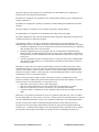
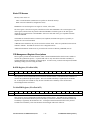
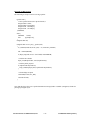
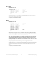
802.11 Direct Sequence Frame Format
Figure 3.2 depicts the frame format used for each packet transmission.
SYNC
128bits
SFD
16 bits
PLCP Preamble
144 bits
SIGNAL
8 bits
SERVICE
8 bits
PLCP Header
48 bits
LENGTH
16 bits
CRC
16 bits
MPDU
PPDU
Figure 3.2 - PHY Header Description
Each frame consists of a PHY header which is always transmitted at the 1 Mbit/s data rate. The PHY
header (which is protected by a CRC-16) indicates the data rate and length of the data portion of the
payload. The PHY header is made up of the following components:
• A PLCP synchronization field which consists of 128 bits of scrambled ones. This portion of the
signal is used to detect the presence of a signal, provide a waveform on which to perform antenna
diversity as well as provide a constant pattern useful for determining accurate symbol timing.
• A Start Frame Delimiter (SFD) is a 16 bit pattern used to provide symbol level synchronization.
• An 8 bit 802.11 Signal Field indicates to the PHY the modulation which shall be used for
transmission (and reception) of the MPDU. The data rate shall be equal to the Signal Field value
multiplied by 100kbit/s. The DSSS PHY currently supports two mandatory modulation services
given by the following 8 bit words, where the LSB shall be transmitted first in time:
•
•
•
a) 0Ah for 1 Mbit/s DBPSK
b) 14h for 2 Mbit/s DQPSK
c) 37h for 5.5 Mbits/s CCK (PC4800 only)
d) 6Eh for 11 Mbits/s CCK (PC4800 only)
The 8 bit 802.11 service field shall be reserved for future use. The value of 00h signifies 802.11
device compliance.
16
An unsigned 16 bit integer Length field used to indicate the number of microseconds (16 to 2 -1)
required to transmit the MPDU octets contained in the data portion of the frame.
A Header Error Check field which is a 16 bit CRC applied over the length and signaling fields to
ensure data integrity.
The PSDU portion of the frame contains the MAC data and control information. Each PSDU frame
consists of the following basic components:
a)
b)
c)
A MAC Header, which comprises frame control, duration, address and sequence control
information.
A variable length Frame Body, which contains information specific to the frame type.
A Frame Check Sequence (FCS) which contains an IEEE 32-bit CRC.
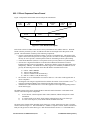
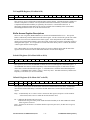
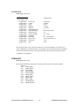
The MAC Frame formats differ depending on the frame type (control, management or data). The basic
format is shown in Figure 3.3. The fields Address 2, Address 3, Sequence Control, Address 4 and Frame
Body are only present in certain frame types. Each field is defined in section 7.1.3 of the IEEE 802.11
Aironet Wireless Communications, Inc.
3-3
Confidential and Proprietary
specification. The format of each of the individual frame types is defined in section 7.2 of the IEEE
802.11 specification.
Octets: 2
2
Frame
Control
Duration/
ID
6
6
6
Address 1 Address 2 Address 3
2
6
Sequence
Address 4
Control
0 - 2312
4
Frame
Body
FCS
MAC Header
Figure 3.3 - MAC Control Information
The 2 byte Frame Control field consists of the following sub-fields: Protocol Version, Type, Subtype, To
DS, From DS, More Fragments, Retry, Power Management, More Data, WEP and Order.
The Duration/ID field is 16 bits in length. The contents of the this field is as follows:
a)
b)
In Control Type frames of subtype PS-Poll, the Duration/ID field carries the association
identity (AID) of the station that transmitted the frame in the 14 least-significant bits, with
the 2 most-significant bits both set to 1. The value of the AID is in the range 1 - 2007.
In all other frames the Duration/ID field contains a duration value as defined for each frame
type in section 7.2 of the 802.11 specification. For frames transmitted during the contention
free period the duration field is set to 32768.
There are four address fields in the MAC frame format. These fields are used to indicate the BSSID,
source address, destination address, transmitting station address and receiving station address. Each
Address field contains a 48-bit address as defined in 5.2 of IEEE Std 802-1990.
The Sequence Control field is 16 bits in length and consists of two subfields, the Sequence Number and
the Fragment number.
The Frame Body is a variable length field and contains information specific to individual frame types and
subtypes. The minimum frame body is zero octets. The maximum length frame body is defined by the
maximum length (MSDU + ICV + IV); where ICV and IV are the WEP fields defined in section 8.2.5 of
the IEEE 802.11 specification.
The FCS field is a 32 bit field containing a 32-bit Cyclic Redundancy Check (CRC). The FCS is
calculated over all the fields of the MAC header and the frame body field.
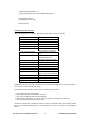
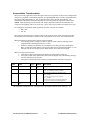
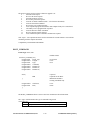
Table 3.1 indicates all of the defined 802.11 frame types.
Aironet Wireless Communications, Inc.
3-4
Confidential and Proprietary
Basic Station operation
A Station keeps two state variables for each station with which direct communication via the wireless
medium is needed:
Authentication State:
The values are: Unauthenticated and Authenticated.
Association State:
The values are: Unassociated and Associated.
These two variables create three local states for each remote station:
State 1:
Initial start state, Unauthenticated, Unassociated.
State 2:
Authenticated, not Associated
State 3:
Authenticated and Associated.
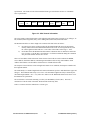
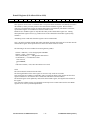
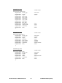
The relationships between these station state variables and the station services are shown in Figure 3.4.
Aironet Wireless Communications, Inc.
3-5
Confidential and Proprietary
Table 3.1 – 802.11 Frame Types
Subtype Value
b7 b6 b5 b4
MANAGEMENT frames (type 00)
0000
0001
0010
0011
0100
0101
0110-0111
1000
1001
1010
1011
1100
1101-1111
CONTROL frames (type 01)
0000-1001
1010
1011
1100
1101
1110
1111
DATA frames (type 10)
0000
0001
0010
0011
0100
0101
0110
0111
1000-1111
Reserved (type 11)
0000-1111
Aironet Wireless Communications, Inc.
Subtype Description
Association Request
Association Response
Reassociation Request
Reassociation Response
Probe Request
Probe Response
Reserved
Beacon
ATIM
Disassociation
Authentication
Deauthentication
Reserved
Reserved
PS-Poll
RTS
CTS
ACK
CF-End
CF-End + CF-Ack
Data
Data + CF-Ack
Data + CF-Poll
Data + CF-Ack + CF-Poll
Null Function (no data)
CF-Ack (no data)
CF-Poll (no data)
CF-Ack + CF-Poll (no data)
Reserved
Reserved
3-6
Confidential and Proprietary
State 1:
Unauthenticated,
Unassociated
Class 1
Frames
Successful
Authentication
DeAuthentication
Notification
DeAuthentication
Notification
State 2:
Authenticated,
Unassociated
Class 1 & 2
Frames
Successful
Association or
Reassociation
Class 1, 2 & 3
Frames
Disassocaiation
Notification
State 3:
Authenticated
and Associated
Figure 3.4 - Relationship Between State Variables and Services
The current state existing between the source and destination station determines the 802.11 frame types
which may be exchanged between that pair of stations (see section 7 of the 802.11 specification). The
state of the sending station given by Figure 3.4 is with respect to the intended receiving station. The
allowed frame types are grouped into classes and the classes correspond to the station state. In State 1
only Class 1 frames are allowed. In State 2 either Class 1 or Class 2 frames are allowed. In State 3, all
frames are allowed (Class 1, 2 and 3). The frame classes are defined as follows:
Class 1 frames (permitted from within States 1, 2 and 3):
Control Frames:
•
RTS
•
CTS
•
ACK
•
CF-End+ACK
•
CF-End
Management Frames:
•
Probe Request/Response
•
Beacon
•
Authentication
Successful authentication enables a station to exchange Class 2 frames. Unsuccessful
authentication leaves the Station in state 1.
•
Deauthentication
Deauthentication notification when in state 2 or state 3 changes the station’s state to
state 1.
The station must become authenticated again prior to sending class 2 frames.
•
ATIM
Data frames:
•
Data
Data frames with FC control bits "To DS” and “From DS" both false.
Aironet Wireless Communications, Inc.
3-7
Confidential and Proprietary
Class 2 frames (if and only if authenticated; allowed from within state 2 and state 3 only):
Management frames:
•
Association Request/Response
Successful association enables Class 3 frames.
Unsuccessful association leaves station in state 2.
•
Reassociation Request/Response
Successful reassociation enables Class 3 frames.
Unsuccessful reassociation leaves the station in State 2 (with respect to the station which
was sent the reassociation message). Reassociation frames shall only be sent if the
sending station is already associated in the same ESS.
•
Disassociation
Disassociation notification when in state 3 changes a station’s state to state 2. This
station must become associated again if it wishes to utilize the DS.
If station A receives a class 2 frame with a unicast address in the Address 1 field from station B which is
not authenticated with station A, station A will send a deauthentication frame to station B.
Class 3 frames (if and only if associated; allowed only from within State 3):
Data frames:
•
Data subtypes
Data frames allowed. That is, either the "To DS" or "From DS" FC control bits may be
set to true to utilize DS Services.
Management frames:
•
Deauthentication
Deauthentication notification when in state 3 implies disassociation as well, changing
the station’s state from 3 to 1. The station must become Authenticated again prior to
another association.
Control frames:
•
PS-Poll
If station A receives a class 3 frame with a unicast address in the Address 1 field from station B which is
authenticated but not associated with station A, station A will send a disassociation frame to station B.
If station A receives a class 3 frame with a unicast address in the Address 1 field from station B which is
not authenticated with station A, station A will send a deauthentication frame to station B.
(The use of the word “receive” refers to a frame which meets all of the filtering criteria specified in
sections 8 and 9 of the 802.11 specification.)
Aironet Wireless Communications, Inc.
3-8
Confidential and Proprietary
Aironet Wireless Communications, Inc.
3-9
Confidential and Proprietary
P
A
R
T
3
4
CHAPTER 4
A
PCMCIA Hardware Interface Operation
This chapter details the hardware aspects of the PC4500/4800 PCMCIA host interface. See Chapter 7 for
details about the PCMCIA software interface.
PCMCIA Hardware
The PC4500/4800 PCMCIA interface is compliant to the PCMCIA PC Card standard electrical and
physical specifications and fully supports 8 and 16 bit transfers. The tables below summarize the
interface signals. For complete descriptions, see the PCMCIA PC Card standard. This interface provides
access to attribute memory (CIS configuration data) and I/O memory (host registers).
Access to the MAC controller registers and shared memory is via 32 (16-bit) registers mapped into the
host I/O space. The PC4500/4800 also requires a host interrupt for interrupt driven buffer processing.
The provision of these resources is typically performed with the interaction of card and socket services
and the host-side device driver.
For more complete information about the PCMCIA electrical interface, see the PCMCIA PC Card
standard.
See Appendix C for descriptions about several utility programs provided on the OEM Developer disk
which are useful for debugging the PC4500/4800 operation. These utilities allow the user to switch the
PC4500/4800 operation between PCMCIA, ISA, and Serial modes, upgrade the PC4500/4800 firmware,
and perform routine diagnostics.
Aironet Wireless Communications, Inc.
4-1
Confidential and Proprietary
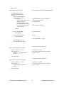
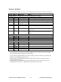
PCMCIA Electrical Connections
PIN #
1
34
35
68
17
51
18
52
PC4500/4800 Power Connections
I/O
NAME
FUNCTION
DC
GND
Ground
DC
GND
Ground
DC
GND
Ground
DC
GND
Ground
DC
VCC
5V supply voltage
DC
VCC
5V supply voltage
DC
VPP1
Programming supply voltage,
Host mode selection switch
DC
VPP2
Programming supply voltage,
Host mode selection switch
Notes:
VPP – both VPP lines should be set to 5V on start up in order to indicate PCMCIA host mode.
PC4500/4800 Address Connections
PIN #
11
12
22
23
24
25
26
27
28
29
I/O
I
I
I
I
I
I
I
I
I
I
NAME
A9
A8
A7
A6
A5
A4
A3
A2
A1
A0
FUNCTION
Address bit 9
Address bit 8
Address bit 7
Address bit 6
Address bit 5
Address bit 4
Address bit 3
Address bit 2
Address bit 1
Address bit 0
Notes:
A[9:0] - Input signals for access to an attribute range of 256 even bytes (0-512) and an I/O space
of 32 words as described in the software description. (A[9:6] are not used to access the I/O
registers.)
Aironet Wireless Communications, Inc.
4-2
Confidential and Proprietary
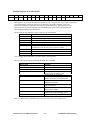
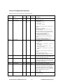
PC4500/4800 Data Connections
PIN #
41
40
39
38
37
66
65
64
6
5
4
3
2
32
31
30
I/O
I/O
I/O
I/O
I/O
I/O
I/O
I/O
I/O
I/O
I/O
I/O
I/O
I/O
I/O
I/O
I/O
NAME
D15
D14
D13
D12
D11
D10
D9
D8
D7
D6
D5
D4
D3
D2
D1
D0
FUNCTION
Data bit 15
Data bit 14
Data bit 13
Data bit 12
Data bit 11
Data bit 10
Data bit 9
Data bit 8
Data bit 7
Data bit 6
Data bit 5
Data bit 4
Data bit 3
Data bit 2
Data bit 1
Data bit 0
Notes:
D[15:0] - Bidirectional data bus signals for even-byte access to the attribute memory as well as byteonly or word-only access to the host I/O space.
PIN #
7
42
9
15
16
33
44
45
58
59
60
61
63
PC4500/4800 Control Connections
I/O
NAME
FUNCTION
I
CE1#
Card Enable #1
I
CE2#
Card Enable #2
I
OE#
Output Enable
I
WE#
Write Enable
O
IREQ#
Interrupt Request (see notes)
O
IOIS16#
I/O port is 16-bit wide , pulled low
on PC4500/4800
I
IORD#
I/O Read
I
IOWR#
I/O Write
I
RESET
Card Reset - pulled high on
PC4500/4800
O
WAIT#
Extended Bus Cycle (see notes)
O
INPACK#
Input Port Acknowledge
I
REG#
Register Select and I/O Enable pulled high on PC4500/4800
O
STSCHG#
Open collector output pulled high
on PC4500/4800. Used in power
saving mode to wake up the host.
Aironet Wireless Communications, Inc.
4-3
Confidential and Proprietary
Notes:
CE1#, CE2#, IORD#, IOWR#, OE#, REG#, WAIT#, WE# - Input signals for bus control as defined
in the PCMCIA standard.
INPACK#, IOIS16#, STSCHG# - Output signals for bus control as defined in the PCMCIA standard.
RESET - Input signal for resetting the PC4500/4800. This signal must be asserted for a minimum of
20 microseconds.
IREQ# - Output signal that functions as the RDY/BSY line following the deassertion of the RESET
signal until the PC4500/4800 is configured and ready for operation. All access to the PC4500/4800
must be held off until this signal goes high. Once the reset operation is complete (interrupts are
enabled via the PCMCIA Configuration Options Register), this signal functions as a level-sensitive
interrupt to the host.
The WAIT# signal must be fully supported. A fixed number of wait states will not be sufficient for
the PC4500/4800 interface.
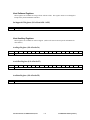
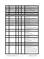
PIN#
36
67
PC4500/4800 Card ID Connections
I/O
NAME
FUNCTION
O
CD1#
Card Detect #1 - connected to
ground on PC4500/4800
O
CD2#
Card Detect #2 – connected to
ground on PC4500/4800
Notes:
The Card Detect pins are used by the socket controller to determine if a card is inserted into a
PCMCIA slot.
Aironet Wireless Communications, Inc.
4-4
Confidential and Proprietary
PIN #
43
57
62
8
10
21
13
14
20
19
46
47
48
49
50
53
54
55
56
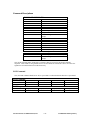
PC4500/4800 Unused Connections
I/O
NAME
FUNCTION
O
VS#1
O
VS#2
O
SPKR#
This pin is pulled high on the
PC4500/4800
I
A10
I
A11
I
A12
I
A13
I
A14
I
A15
I
A16
I
A17
I
A18
I
A19
I
A20
This pin is used as DTR for
Serial mode operation
I
A21
This pin is used as RTS for Serial
mode operation
I
A22
This pin is used as CTS for Serial
mode operation
I
A23
This pin is used as DCD for
Serial mode operation
I
A24
This pin is used as RXD for
Serial mode operation
I
A25
This pin is used as TXD for
Serial mode operation
Notes:
The above list of unused pins are ignored (or not used) during normal PCMCIA mode operation.
Aironet Wireless Communications, Inc.
4-5
Confidential and Proprietary
5
CHAPTER 5
A
ISA Hardware Interface Operation
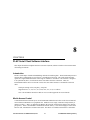
This chapter details the hardware aspects of the PC4500/4800 ISA host interface. See Chapter 7 for details
about the ISA software interface.
ISA Hardware
The PC4500/4800 ISA interface functions as either an 8-bit (byte only) or a 16-bit (word only) I/O
interface device. The interface does not adhere to all signal definitions according to the ISA specification
as some signals must be driven according to the PCMCIA specification. External address decode circuitry
and control signal gating is required. The tables below summarize the interface signals. This interface
provides access to the PC4500/4800 I/O memory (host registers).
Access to the MAC controller registers and shared memory is via 32 (16-bit) registers mapped into the host
I/O space. The PC4500/4800 also requires a host interrupt channel for communication synchronization.
The provision of these resources are typically performed by the host hardware and the host-side device
driver.
For more complete information about the ISA electrical interface, refer to IEEE specification 996 or the
text by Edward Solari (see the Applicable Documents section on page x).
ISA Mode
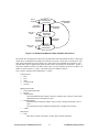
ISA mode on the PC4500/4800 uses PCMCIA timing and signals. It is called ISA mode in the sense that
the PCMCIA configuration registers are not accessed in order to enable the card. The PC4500/4800
supports ISA mode by tying the VPP2 PCMCIA pin low at reset in order to enable the host interface. In
this mode, the PCMCIA configuration registers are disabled and cannot be accessed. Likewise, the
Aironet Wireless Communications, Inc.
5-1
Confidential and Proprietary
Configuration Options register (COR) does not need to be written to access the card. All other interface
registers act the same. All signals and timings are the same as in PCMCIA mode except that the sense of
the interrupt line becomes active high in ISA mode.
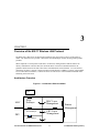
In ISA mode, the PC4500/4800 requires external hardware to determine the IRQ and I/O base address that
the card uses. The main requirements are the decoding of the upper address lines to generate a chip select
and route the interrupt line to the desired interrupt. IOIS16# is always decoded as the cards can always
respond to 16-bit accesses. The difference for ISA mode, is that the ISA bus requires this signal to be wire
or’d with the signals from other cards on the ISA bus. This requires that an open collector gate be used.
The PC4500/4800 has an onboard reset controller which insures that the radio comes up properly after +5V
is applied to the card. However, this does not preclude the use of an external reset circuit.
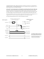
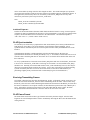
The following diagram illustrates the use of the PC4500/4800 in ISA mode.
ISA bus signals
The desired 64 byte address block must be
decoded by external hardware.
LM4500/4800 pcmcia
signals
EN
ISA_AD[15:6]
Upper Address
Decode
+5vdc
gnd
PCMCIA_VPP1
PCMCIA_VPP2
ISA_AEN
PCMCIA_CE1#
ISA_SBHE
PCMCIA_CE2#
ISA_A[0]
ISA_IOCS16*
ISA_IOWR*
PCMCIA_IOWR#
ISA_IORD*
PCMCIA_IORD#
ISA_INT
PCMCIA_IREQ#
The LM4500 and LM4800 invert the interrupt
line in ISA mode. The ISA int signal is active
high, the PCMCIA IREQ# signal is active low.
PCMCIA_D[15:0]
The LM4500/4800 will only drive 4mA on the
data bus. So, for some applications,
external bus drivers may be required.
ISA_D[15:0]
ISA_AD[5:0]
PCMCIA_AD[5:0]
Aironet Wireless Communications, Inc.
5-2
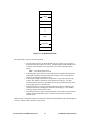
Confidential and Proprietary
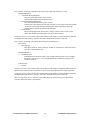
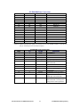
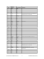
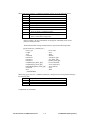
PCMCIA
definition
GND
D3
D4
D5
D6
D7
CE1#
ISA definition
GND
D3
D4
D5
D6
D7
CE1#
8
9
10
11
12
13
14
15
16
17
18
19
20
21
22
23
24
25
26
27
28
29
30
31
32
33
34
35
36
37
38
39
40
41
42
A10
OE#
A11
A9
A8
A13
A14
WE#
IREQ#
VCC
VPP1
A16
A15
A12
A7
A6
A5
A4
A3
A2
A1
A0
D0
D1
D2
IOIS16#
GND
GND
CD1#
D11
D12
D13
D14
D15
CE2#
N/C
MEMR
N/C
A9
A8
N/C
N/C
MEMW
INT0
VCC
VCC
A16
A15
A12
A7
A6
A5
A4
A3
A2
A1
A0
D0
D1
D2
IOCS16#
GND
GND
N/C
D11
D12
D13
D14
D15
CE2#
43
44
45
VS1
IORD#
IOWR#
N/C
IOR#
IOW#
46
47
48
49
50
A17
A18
A19
A20
A21
N/C
N/C
N/C
N/C
N/C
PIN
1
2
3
4
5
6
7
Aironet Wireless Communications, Inc.
Comments
Lower byte of CS (active low) ; CE1 and CE2 are
both driven low for a 16 bit access
(See Note 4)
Tied low on the PC4500/4800 (See Note 2)
Upper byte of CS (active low); CE1 and CE2 are
both driven low for a 16 bit access
I/O Read Strobe, active low
I/O Write Strobe, active low , pulled high
(See Note 4)
5-3
Confidential and Proprietary
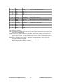
51
52
53
54
55
56
57
58
59
60
61
62
63
64
65
66
67
68
VCC
VPP2
A22
A23
A24
A25
VS2
RESET
WAIT#
INPACK
REG#
SPKR
STSCHG
D8
D9
D10
CD2
GND
VCC
GND
N/C
N/C
N/C
N/C
N/C
RESET
IOCHRDY
N/C
REG#
N/C
STSCHG
D8
D9
D10
N/C
GND
Sets ISA mode; enabling interface
Active high
Active low (See Note 3)
(See Note 5)
Must be driven low according to PCMCIA spec
Open collector output signal
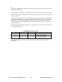
Notes:
1
N/C indicates not connected.
2
The PC4500/4800 fully supports 8 bit I/O as well as 16-bit I/O. Since IOIS16# is tied to ground, it is not
shown on the timing diagrams.
3
Support of the WAIT# signal is required. Typical pulse widths for this signal are 250 to 500 nsec, but
can be as long as 875 nsec. Accesses to hardware base registers will have a WAIT# pulse width of
approximately 125nsec.
4
Both memory writes and I/O writes require a minimum valid data setup time of 15nsec ahead of the
rising edge of MEMW# or IOWR#.
5
The INPACK signal is returned for all I/O accesses. The use of this signal is not required since the
address is fully decoded by the socket controller.
Aironet Wireless Communications, Inc.
5-4
Confidential and Proprietary
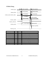
I/O Read Cycle
tsu AD[7:0] IORD#
th A[7:0] (IORD#)
PCMCIA_A[9:0]
tsu REG# (IORD#)
th REG# (IORD#)
tsu CE# (IORD#)
th CE# (IORD#)
PCMCIA_REG#
PCMCIA_CE1#, PCMCIA_CE2#
tw IORD#
td INPACK# IORD#
td WAIT# (IORD#)
td INPACK# IORD#
th D[15:0] (IORD#)
PCMCIA_IORD#
PCMCIA _INPACK#
tw (WAIT#)
tdr D[15:0] (WAIT#)
PCMCIA_WAIT#
thd D[15:0] (IORD#)
PCMCIA_D[15:0]
NAME
tw (WAIT#)
tw (IORD#)
tsu REG# (IORD#)
tsu CE# (IORD#)
tsu A[7:0] (IORD#)
td INPACK# (IORD#)
td WAIT# (IORD#)
th A[7:0] (IORD#)
th REG# (IORD#)
th CE# (IORD#)
th D[15:0] (IORD#)
tdr D[15:0] (WAIT#)
thd D[15:0] (IORD#)
Min (ns)
125
165
5
30
30
Max (ns)
12,000
45
35
20
0
20
0
0
30
Aironet Wireless Communications, Inc.
Comment
WAIT# pulse width
IORD# pulse width
REG# setup before falling IORD#
CE# setup before falling IORD#
A[7:0] setup before falling IORD#
INPACK# delay before falling IORD#
WAIT# delay following IORD#
A[7:0] hold following rising IORD#
REG# hold following rising IORD#
CE# hold following rising IORD#
D[15:0] hold following rising IORD#
D[15:0] delay following rising WAIT#
D[15:0] hold following rising IORD#
5-5
Confidential and Proprietary
I/O Write Timing
tsu AD[7:0] IOWR#
th A[7:0] (IOWR#)
tsu REG# (IOWR#)
th REG# (IOWR#)
PCMCIA_A[8:0]
PCMCIA_REG#
tsu CE# (IOWR#)
th CE# (IOWR#)
PCMCIA_CE1#, PCMCIA_CE2#
tw IOWR#
td WAIT# (IOWR#)
td INPACK# IOWR#
tsu D[15:0] IOWR#
td INPACK# IOWR#
th D[15:0] (IOWR#)
PCMCIA_IOWR#
PCMCIA _INPACK#
tw (WAIT#)
td IOWR# (WAIT#)
PCMCIA_WAIT#
thd D[15:0] (IOWR#)
PCMCIA_D[15:0]
NAME
tw (WAIT#)
tw (IOWR#)
tsu REG# (IOWR#)
tsu CE# (IOWR#)
tsu A[7:0] (IOWR#)
td INPACK# (IOWR#)
td WAIT# (IOWR#)
th A[7:0] (IOWR#)
th REG# (IOWR#)
th CE# (IOWR#)
th D[15:0] (IOWR#)
thd D[15:0] (IOWR#)
td IOWR# (WAIT#)
tsu D[15:0] (IOWR#)
Min (ns)
125
165
5
30
30
Max (ns)
12,000
45
35
20
0
20
0
30
0
15
Aironet Wireless Communications, Inc.
Comment
WAIT# pulse width
IOWR# pulse width
REG# setup before falling IOWR#
CE# setup before falling IOWR#
A[7:0] setup before falling IOWR#
INPACK# delay before falling IOWR#
WAIT# delay following IOWR#
A[7:0] hold following rising IOWR#
REG# hold following rising IOWR#
CE# hold following rising IOWR#
D[15:0] hold following rising IOWR#
D[15:0] hold following rising IOWR#
IOWR# delay from rising WAIT#
D[15:0] setup before falling IOWR#
5-6
Confidential and Proprietary
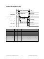
Attribute Memory Read Timing
3
1
tsu AD[7:0] (OE#)
th A[9:0] (OE#)
tsu REG# (OE#)
th REG# (OE#)
PCMCIA_A[9:0]
PCMCIA_REG#
tsu CE# (OE#)
th CE# (OE#)
PCMCIA_CE1#, PCMCIA_CE2#
tw OE#
td WAIT# (OE#)
tsu D[15:0] OE#
th D[15:0] (OE#)
PCMCIA_OE#
tw (WAIT#)
td OE# (WAIT#)
PCMCIA_WAIT#
thd D[15:0] (OE#)
PCMCIA_D[15:0]
NAME
tw (WAIT#)
tw (OE#)
tsu REG# (OE#)
tsu CE# (OE#)
tsu A[7:0] (OE#)
td WAIT# (OE#)
th A[9:0] (OE#)
th REG# (OE#)
th CE# (OE#)
th D[15:0] (OE#)
thd D[15:0] (OE#)
td OE# (WAIT#)
tsu D[15:0] (OE#)
Min (ns)
250
150
5
0
30
Max (ns)
12,000
35
20
0
20
0
30
0
15
Aironet Wireless Communications, Inc.
Comment
WAIT# pulse width
OE# pulse width
REG# setup before falling OE#
CE# setup before falling OE#
A[7:0] setup before falling OE#
WAIT# delay following OE#
A[7:0] hold following rising OE#
REG# hold following rising OE#
CE# hold following rising OE#
D[15:0] hold following rising OE#
D[15:0] hold following rising OE#
OE# delay from rising WAIT#
D[15:0] setup before falling OE#
5-7
Confidential and Proprietary
Attribute Memory Write Timing
tsu AD[7:0] WE#
th A[7:0] (WE#)
tsu REG# (WE#)
th REG# (WE#)
PCMCIA_A[8:0]
PCMCIA_REG#
tsu CE# (WE#)
th CE# (WE#)
PCMCIA_CE1#, PCMCIA_CE2#
tw WE#
tsu D[15:0] WE#
td WAIT# (WE#)
th D[15:0] (WE#)
PCMCIA_WE#
tw (WAIT#)
td IOWR# (WAIT#)
PCMCIA_WAIT#
thd D[15:0] (WE#)
PCMCIA_D[15:0]
NAME
tw (WAIT#)
tw (WE#)
tsu REG# (WE#)
tsu CE# (WE#)
tsu A[7:0] (WE#)
td WAIT# (WE#)
th A[7:0] (WE#)
th REG# (WE#)
th CE# (WE#)
th D[15:0] (WE#)
thd D[15:0] (WE#)
td IOWR# (WAIT#)
tsu D[15:0] (WE#)
Min (ns)
125
165
5
30
30
Max (ns)
12,000
35
20
0
20
0
30
0
15
Aironet Wireless Communications, Inc.
Comment
WAIT# pulse width
WE# pulse width
REG# setup before falling WE#
CE# setup before falling WE#
A[7:0] setup before falling WE#
WAIT# delay following WE#
A[7:0] hold following rising WE#
REG# hold following rising WE#
CE# hold following rising WE#
D[15:0] hold following rising WE#
D[15:0] hold following rising WE#
IOWR# delay from rising WAIT#
D[15:0] setup before falling WE#
5-8
Confidential and Proprietary
6
CHAPTER 6
A
Serial Hardware Interface Operation
This chapter details the hardware aspects of the PC4500/4800 Serial host interface. See chapter 8 for
details about the available software interfaces.
Serial Hardware
The PC4500/4800 PC card offers a Serial Interface mode to the host device by re-mapping the upper
PCMCIA address lines to a UART-type serial interface. This allows the PC4500/4800 to be embedded
and interfaced to via a serial port. The serial interface can be accessed using a serial protocol referred to
as PLAP.
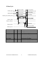
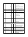
Serial Mode
The Serial mode is invoked automatically by the PC4500/4800 PC card upon a read of the VPP lines as
listed in Table 6-2, and the reception of the autobaud sequence.
A power-on reset signal is provided internally. No external reset signal is required. The standard
PCMCIA Card Reset signal (pin 58) is still available, being wire OR’d with the internal reset. This
arrangement is present in both PCMCIA and Serial modes. Typical Serial mode applications require pin
58 to be driven low.
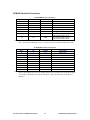
Table 6-1 lists the operating parameters of the PC4500/4800 Serial Mode interface.
Aironet Wireless Communications, Inc.
6-1
Confidential and Proprietary
Serial Port Mode Specifications
SPECIFICATION
7200 bit/s to 115.2 kbit/s using
no parity, 8 data bits, 2 stop bits
Voltage Levels
TTL levels supported
ViL < 0.8V
VoL < 0.3V
ViH > 2.0V
VoH > 3.0V
ITEM
Baud Rates
Signal Polarity
RXD, TXD (NRZ data, non inverted)
CTS, RTS (active low)
DSR, RING (active low)
BUSY_IN, BUSY_OUT (active high)
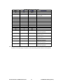
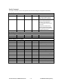
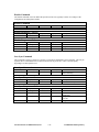
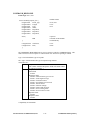
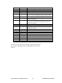
When Serial mode is required, the PC Card connections should be as shown in Table 6-2.
PIN#
PCMCIA
NAME
1
2
3
4
5
6
7
8
9
10
11
12
13
14
15
16
17
18
19
20
21
22
23
24
25
26
27
28
29
30
31
32
33
34
GND
D3
D4
D5
D6
D7
CE1#
A10
OE#
A11
A9
A8
A13
A14
WE#
IREQ#
VCC
VPP1
A16
A15
A12
A7
A6
A5
A4
A3
A2
A1
A0
D0
D1
D2
IOIS16#
GND
Serial Mode Pinouts
SERIAL
FUNCTION
MODE
CONNECTION
Grounded
Grounded
Grounded
Grounded
Grounded
Grounded
Tied high
N/C
Tied high
N/C
Grounded
+5V
N/C
N/C
Tied high
Tie to VCC (no pull-up required)
N/C
apply VCC
+5V
Used as Mode pin
N/C
N/C
N/C
Grounded
Grounded
Grounded
Grounded
+5V
Grounded
Grounded
Grounded
Grounded
Grounded
Grounded
N/C
Grounded
Aironet Wireless Communications, Inc.
6-2
Confidential and Proprietary
35
36
37
38
39
40
41
42
43
44
45
46
47
48
49
50
51
52
53
54
55
56
57
58
GND
CD#1
D11
D12
D13
D14
D15
CE2#
VS1#
IORD#
IOWR#
A17
A18
A19
A20
A21
VCC
VPP2
A22
A23
A24
A25
VS2
RESET
Grounded
N/C
Grounded
Grounded
Grounded
Grounded
Grounded
Tied high
N/C
Tied high
Tied high
N/C
RING
DSR
DTR/BO
RTS#
Apply VCC
Grounded
CTS#
DCD/BI
RXD
TXD
N/C
RESET
59
60
61
62
63
WAIT#
INPACK#
REG#
SPKR#
STSCHG#
N/C
N/C
Tied high
N/C
O.C. output
64
65
66
67
68
D8
D9
D10
CD2#
GND
Connected to ground on the PC4500/4800
Tie to VCC (no pull-up required)
RING is output from card (active low)
DSR is output from card (active low)
DTR/BUSY OUT is input to card (active high)
RTS is input to card (active low)
Mode input
CTS is output from card (active low)
DCD/BUSY IN is output from card (active high)
RXD is input to card (NRZ data)
TXD is output from card (NRZ data)
Optional input – OR’d with internal reset
controller signal (active high);
use minimum 20 usec pulse, pulled high on
PC4500/4800. See note below.
Open collector output – Can be used for wake up
event
Grounded
Grounded
Grounded
N/C
Grounded
Connected to ground on the PC4500/4800
Note: the RESET signal is pulled high on the PC4500/4800, therefore, for the card to boot in serial mode,
this signal must be driven low.
Aironet Wireless Communications, Inc.
6-3
Confidential and Proprietary
The following page provides a schematic to be used for interfacing the PC4500/4800 using a serial
interface. This is a general drawing intended to be used with several Aironet PCMCIA card devices. The
address and data lines of the PCMCIA connector can be left unconnected or may be tied to ground for
proper PC4500/4800 operation.
The following table gives some part number cross references.
Aironet Part #
670-002859
672-000347
672-002906
672-003601
Description
Right Angle Switch
DB9 female connector
68 pin PCMCIA socket
4 pin power connector
Vendor
MORS Components
AMP Incorporated
Berg Electronics
Weidmuller Inc.
Vendor #
MJTP1236E
787844-4
92789-050
151286
Serial Port Schematic
A suggested schematic for a serial port is shown on the following page.
Aironet Wireless Communications, Inc.
6-4
Confidential and Proprietary
Aironet Wireless Communications, Inc.
6-6
Confidential and Proprietary
P
A
R
T
4
7
CHAPTER 7
A
PCMCIA and ISA Client Software Interface
This chapter details the software interface to the PC4500/4800. Refer to chapters 4 and 5 for details
about the PCMCIA and ISA hardware interfaces.
The main software components in a PCMCIA environment are Card Services and Socket Services. The
use of these services provides sufficient abstraction to allow the use of multiple PC cards through
different PCMCIA interface hardware. Socket Services provides actual PCMCIA hardware interface
support and Card Services provides client processes access to the PC cards that are in use. Once a client
registers with card services, it will then be informed of relevant events pertaining to the PC cards
currently installed.
The PC4500/4800 is accessed via 32 contiguous 16-bit I/O registers. Each register is assigned an offset
which relates to the base port address used by the socket. (Base port address plus offset yields the port
address through which each register is accessed.) Since all registers are 16-bit registers, two I/O ports are
used for register access. The hardware will transfer 8 bits via the respective port address and 8 bits via
port address+1. Therefore, an area of 64 continuous I/O ports are required for PC4500/4800 controller
access.
All sample code shown in this chapter uses “PC4500” as a part of variable names and in comments. This
sample code, however, is appropriate for use with the PC4800 as well.
Host Memory Map
The host has two memory spaces available to it: I/O Space and Attribute Memory. Common memory is
not available on the PC4500/4800.
Aironet Wireless Communications, Inc.
7-1
Confidential and Proprietary
Host Attribute Memory
The host attribute memory consists of the CIS and the attribute memory registers. The complete
PC4500/4800 CIS description can be found in Appendix B.
The CIS is copied from the flash to the RAM during power on reset. (The READY signal remains
deasserted until the copy process is completed.)
Offset
000H-300H
3E0H
3E2H
3E4H
3E6H
Table 7.1 – Card Configuration Information
Description
Card Information Structure (CIS)
Configuration Option Register must set to 0x45 to enable Host
control (I/O) Registers.
Card Configuration and Status Register
Pin Replacement Register
Socket and Copy Register (not used)
Host Common Memory
There is no common memory accessible on the PC4500/4800.
Host I/O Registers
The host has 32 consecutive 16-bit I/O registers for accessing the PC4500/4800 card. Table 7-2 lists the
register assignments according to functionality.
All registers (except for the Data0, Data1 and AuxData) can be read without restriction since the read
operation will not impact the PC4500/4800 protocol processor. The exceptions require that an internal
data pointer be affected.
All registers are 16-bit registers, therefore, it is assumed that the host software writes or reads 16 bits per
I/O cycle. If the hardware environment is only capable of transferring 8 bits per I/O cycle, the register
word should be transferred as follows: first the low-order byte (bits 0-7) should be accessed via the I/O
register offset (even), followed by the high-order byte (bits 8-15) via register offset+1 (odd). To prevent
undefined processor behavior, both bytes must be transferred before any other access is allowed
(includes another register access as well as an attribute memory access).
Aironet Wireless Communications, Inc.
7-2
Confidential and Proprietary
The following is sample code for accessing the PC4500/4800 I/O registers:
unsigned short
#if IO_IS_16BIT
Base4500IO;
// I/O base address
#define
#define
#else
OUT4500(register, u16value)
IN4500(register)
outportw(Base4500IO+register, u16value)
inportw(Base4500IO+register)
#define
#define
OUT4500(register, u16value)
IN4500(register)
out4500_8bit(register, u16value)
in4500_8bit(register)
// I/O is 16-bit
// I/O is 8-bit
void out4500_8bit(unsigned short register, unsigned short u16value)
{
push_interrupt_enable_state();
disable_interrupts();
outportb(Base4500IO+register+0, (char)(u16value & 0xFF));
outportb(Base4500IO+register+1, (char)(u16value >> 8));
pop_interrupt_enable_state;
}
unsigned short in4500_8bit(unsigned short register)
{
unsigned short u16RetVal;
push_interrupt_enable_state();
disable_interrupts();
u16RetVal = inportb(Base4500IO+register+0);
u16RetVal += ((u16)inportb(Base4500IO+register+1)) << 8;
pop_interrupt_enable_state;
}
#endif
Aironet Wireless Communications, Inc.
7-3
// save interrupt enable state
// disable interrupts
// restore interrupt enable state
// save interrupt enable state
// disable interrupts
// restore interrupt enable state
Confidential and Proprietary
Table 7.2 – PC4500/4800 Register Summary
Command/Status
Events
0x00
Command
0x30
EvStat
0x02
Param0
0x32
EvIntEn
0x04
Param1
0x34
EvAck
0x06
Param2
0x08
Status
0x28
SWSupport0
0x0A
Resp0
0x2A
SWSupport1
0x0C
Resp1
0x2C
SWSupport2
0x0E
Resp2
0x2E
SWSupport3
Memory (FID/RID) Access
Buffer Access Pointer 0 (BAP0)
0x20
RxFID
0x18
Select0
0x22
TxAllocFID
0x1C
Offset0
0x24
TxComplFID
0x36
Data0
0x10
LinkStatus
Host Software
FID Management
Control
Buffer Access Pointer 1 (BAP1)
0x1A
Select1
Auxiliary Port
0x1E
Offset1
0x3A
AuxPage
0x38
Data1
0x3C
AuxOffset
0x3E AuxData
Note: all other registers are reserved
Recognizing the PC4500/4800
The PC4500 and PC4800 cards can be recognized via the Manufacturer Codes in the Card Information
Structure (CIS) contained in attribute memory. The values are:
Manufacturer Code
PC4500: 0x015F
PC4800: 0x015F
Product Code
PC4500: 0x0005
PC4800: 0x0007
Card services provides a GET_CONFIGURATION_INFO function which returns the manufacturer and
product codes from a socket. Programmers writing their own host software should process the CIS to
verify that the card is a PC4500 or PC4800.
Aironet Wireless Communications, Inc.
7-4
Confidential and Proprietary
Bootstrap -- Starting the PC4500/4800
The following is the correct start sequence from the host perspective.
1.
2.
3.
4.
5.
6.
7.
8.
9.
Wait for Card Detect signals to go active.
Enable power (VCC) to the socket. Also, set VPP1, VPP2 = 5V.
Delay for power to stabilize (200 ms).
Release PCMCIA reset.
Delay at least 10us.
Wait for Card Ready to go active.
Read the CIS to identify card.
Configure socket to have an I/O window with 32 consecutive 16-bit ports.
Set Card Configuration Options Register to 0x45. [Currently this is at address 0x3E0 of attribute
memory; but, use the CIS to determine the correct address]
10. Release PC4500/4800 from reset by issuing a NOP command -- OUT4500(COMMAND,
0x0010).
11. Wait for EvStat.Cmd bit to be set.
12. Ack the command completion by setting EvAck.Cmd.
Resetting the PC4500/4800
Three methods exist to reset the PC4500/4800:
1. use the PCMCIA reset line,
2. by writing a 0x80 into the Configuration Options Register, followed by writing a 0x00 into the
same register (after the initial boot).
3. by issuing the restart command.
Note, when resetting the card, the VPP1 and VPP2 lines must be held at 5V for normal operation.
Startup is then the same as for normal bootstrap of the card.
Aironet Wireless Communications, Inc.
7-5
Confidential and Proprietary
Interrupt Service Routine (ISR) processing
The correct interrupt service routine processing is as follows:
1.Disable the interrupt source on the host (mask the PIC).
2.Prepare the host for another interrupt (EOI the PIC).
3.Determine the active interrupts:
active_interrupts = IN4500(EVSTAT);
Note: even masked interrupts will be active.
4.Process the active interrupts. (See Event Handling for details).
5.Acknowledge the interrupts and disable the interrupt:
OUT4500(EVACK, active_interrupts);
6.Disable interrupts
Note: Disabling and re-enabling the interrupt may be required to ensure that an edge is generated
for the next interrupt:
SaveIntEn = IN4500(INTEN);
OUT4500(INTEN, 0x0000);
7.Unmask the interrupt on the host.
8.Reenable the interrupt:
OUT4500(INTEN, SaveIntEn);
Note: It is important to process the interrupt source before acknowledging, since the acknowledge
may result in loss of information associated with the interrupt source.
Enabling the PC4500/4800
Enabling the PC4500/4800 for operation consists of the following steps:
1.
2.
3.
4.
5.
6.
recognizing the card
boot strapping the PC4500/4800
installing an interrupt service routine
optionally pre-allocating transmit fids
writing the configuration rids
enabling the MAC
Aironet Wireless Communications, Inc.
7-6
Confidential and Proprietary
After bootstrapping, the following is sample code for configuring and enabling the MAC:
tdsCommand
tdsResponse
PC4500_CONFIG
Cmd;
Rsp;
cfg;
typedef struct {
unsigned short
unsigned char
} PC4500_SSID;
SsidLen;
Ssid[32];
struct MySsid {
u16
PC4500_SSID
}={
u16RidLen;
aSSID[2];
0,
{ 6, "MYSSID" }
{ 0, "" }
// see following section for definition
// see following section for definition
// see following section for definition
// PC4500 will ensure that the RidLen is unchanged
// SSID length and value
// zero length SSID to end the list
}
u16 minimum_mac_enable(void)
{
memset(Cmd, 0, sizeof(Cmd));
Cmd.Command = MAC_DISABLE;
issuecommand(&Cmd, &Rsp);
// disable in case already enabled
// general configuration
(read/modify/write)
PC4500_readrid(0xFF10, &cfg, sizeof(cfg));
cfg.u16OperatingMode = MODE_STA_ESS;
PC4500_writerid(0xFF10, &cfg, sizeof(cfg));
// station in ESS mode
// ssid list
PC4500_writerid(0xFF11, &MySsid, sizeof(MySsid));
memset(Cmd, 0, sizeof(Cmd));
Cmd.Command = MAC_ENABLE;
issuecommand(&Cmd, &Rsp);
// enable the MAC
if ((Rsp.Status & 0xFF00) != 0) {
Reason
= Rsp.Resp0;
BadRidNumber = Rsp.Resp1;
BadRidOffset = Rsp.Resp2;
}
return SUCCESS;
}
Aironet Wireless Communications, Inc.
7-7
Confidential and Proprietary
Command and Status Register Descriptions
The PC4500/4800 provides 4 I/O registers for issuing commands to the protocol processor and 4 I/O
registers for status response. These registers provide a command / status interface for sequential protocol
processor control functions. The command code and related information is entered in the Command and
Param registers. The process is executed by the PC4500/4800 and then the resulting status is provided in
the Status and Resp registers. Completion of a command is signaled and acknowledged using the Event
registers.
The command response mechanism provides semaphores on the command/response to prevent the host
from overwriting a command that has not yet been processed and to prevent the PC4500/4800 from
overwriting a response. The mechanism allows the host to issue a new command after the PC4500/4800
has acknowledged, but is still processing the previous command. Note, a command may be stalled in the
Command/Param registers until a previous response is acknowledged.
The sequence for issuing a command to the PC4500/4800 is as follows:
1. wait for Command.Busy to be clear
2. write the required parameters (Param0, Param1, Param2)
3. write the command (Command)
4. wait for EvStat.Cmd to indicate that the command has completed
5. read the completion status and responses (Status, Resp0/1/2)
6. acknowledge the command by setting EvAck.Cmd
When the command completes, the Status register will contain the command code in the lower byte. If
the command completed successfully, the upper byte of the Status will be zero, and Resp0, Resp1 and
Resp2 will contain responses that change depending on the command.
If the command failed, the upper byte of the Status Register will be non-zero, and Resp0 will contain the
error code. Additional information may be conveyed in Resp1 and Resp2 depending on the command.
Some commands allow for successful completion to not be indicated to the host. This is accomplished
by setting the NoResponse bit when writing the Command Register. If the command successfully
executes, there will be no EvStat.Cmd event. If the command fails, a response will be returned as
normal.
If commands are to be issued from multiple contexts (e.g. interrupt routines) then interrupts should be
disabled as appropriate to prevent a context switch from causing improper operation:
1. wait for Command.Busy to be clear
2. disable interrupts;
3. if Command.Busy is set, reenable interrupts and return to step 1
4. write the required parameters (Param0, Param1, Param2)
5. write the command (Command)
6. reenable interrupts;
7. .... as above ...
A command will stall in the command register (Command.Busy won’t clear) if a previous command
completion (EvStat.Cmd is set) has not been acknowledged. Setting EvAck.Cmd will acknowledge the
previously unacknowledged command and allow the firmware to proceed with the new command.
In some circumstances, a command may be issued that is not processed by the PC4500/4800. The
PC4500/4800 will always zero the Command register after accepting the command. If the Command
register is read back with the Command.Busy bit cleared and a non-zero value, then the command should
be reissued by writing the Command register again.
Aironet Wireless Communications, Inc.
7-8
Confidential and Proprietary
In some circumstances Command.Busy also may not clear. This may occur when the host reads the
Command register at the same time as the firmware attempts to clear the Command.Busy bit.
A work-around is available for clearing a stuck Command.Busy, by setting EvAck.ClearCommandBusy.
If the firmware is not processing a command, the Command.Busy bit will be cleared.
The following is an example for issuing a single command:
typedef struct {
unsigned short
unsigned short
unsigned short
unsigned short
} tdsCommand;
Command;
Param0;
Param1;
Param2;
typedef struct {
unsigned short
unsigned short
unsigned short
unsigned short
} tdsResponse;
Status;
Resp0;
Resp1;
Resp2;
unsigned short issuecommand(tdsCommand *pCmd, tdsResponse *pRsp) {
// wait for command.busy to clear normally
// we will only issue one command at a time so no need
OUT4500(PARAM0, pCmd->Param0);
OUT4500(PARAM1, pCmd->Param1);
OUT4500(PARAM2, pCmd->Param2);
OUT4500(COMMAND, pCmd->Command);
while ( (IN4500(EVSTAT) & EV_CMD) == 0) {
if (IN4500(COMMAND) == command) {
// PC4500 didn’t notice command, try again
OUT4500(COMMAND, command);
}
}
// command completed
pRsp->Status = IN4500(STATUS);
pRsp->Resp0 = IN4500(RESP0);
pRsp->Resp1 = IN4500(RESP1);
pRsp->Resp2 = IN4500(RESP2);
// clear stuck command busy if necessary
if (IN4500(COMMAND) & COMMAND_BUSY) {
OUT4500(EVACK, EV_CLEARCOMMANDBUSY);
}
// acknowledge processing the status/response
OUT4500(EVACK, EV_CMD);
}
Aironet Wireless Communications, Inc.
7-9
Confidential and Proprietary
typedef struct {
unsigned short
unsigned short
#define
#define
#define
#define
#define
#define
#define
#define
unsigned short
#define
#define
#define
#define
#define
#define
#define
u16Len;
u16OperatingMode;
unsigned short
unsigned short
unsigned char
unsigned char
unsigned short
unsigned short
unsigned short
unsigned short
unsigned short
unsigned short
unsigned short
unsigned short
MODE_STA_IBSS
MODE_STA_ESS
MODE_AP
MODE_AP_RPTR
MODE_ETHERNET_HOST
MODE_LLC_HOST
MODE_AIRONET_EXTEND
MODE_AP_INTERFACE
u16ReceiveMode;
RXMODE_BC_MC_ADDR
RXMODE_BC_ADDR
RXMODE_ADDR
RXMODE_RFMON
RXMODE_RFMON_ANYBSS
RXMODE_LANMON
RXMODE_DISABLE_802_3_
HEADER
u16FragmentThreshold;
u16RtsThreshold;
au8StationMacAddress[6];
au8Rates[8];
u16ShortRetryLimit;
u16LongRetryLimit;
u16TxLifetime;
u16RxLifetime;
u16Stationary;
u16Ordering;
u16DeviceType;
_reserved1[5];
unsigned short
#define
#define
#define
unsigned short
unsigned short
unsigned short
unsigned short
unsigned short
unsigned short
unsigned short
#define
#define
#define
unsigned short
unsigned short
unsigned short
unsigned short
unsigned short
unsigned short
unsigned short
u16ScanMode;
SCANMODE_ACTIVE
SCANMODE_PASSIVE
SCANMODE_AIROSCAN
u16ProbeDelay;
u16ProbeEnergyTimeout;
u16ProbeResponseTimeout;
u16BeaconListenTimeout;
u16JoinNetTimeout;
u16AuthenticationTimeout;
u16AuthenticationType;
AUTH_OPEN
AUTH_SHAREDKEY
AUTH_EXCLUDENONWEP
u16AssociationTimeout;
u16SpecifiedApTimeout;
u16OfflineScanInterval;
u16OfflineScanDuration;
u16LinkLossDelay;
u16MaxBeaconLostTime;
u16RefreshInterval;
/* sizeof(PC4500_CONFIG) */
/* operating mode
*/
0
1
2
3
(0<<8)
(1<<8)
(1<<9)
(1<<10)
0
1
2
3
4
5
(1<<8)
/* rx payloads converted */
/* rx payloads left as is */
/* enable Aironet extenstions */
/* enable ap interface extensions */
/* receive mode */
/* ignore multicasts */
/* ignore multicast and broadcast */
/* wireless monitor mode */
/* lan style monitor -- data packets only */
/* disables 802.3 header on rx */
/* in kusec */
/* in kusec */
/* for overriding device type */
/*---------- Scanning/Associating ----------*/
Aironet Wireless Communications, Inc.
0
1
2
/* in kusec */
/* in kusec */
1
2
4
7-10
Confidential and Proprietary
#define
unsigned short
DISABLE_REFRESH
_reserved1a[1];
unsigned short
#define
#define
#define
unsigned short
unsigned short
unsigned short
unsigned short
unsigned short
unsigned short
u16PowerSaveMode;
POWERSAVE_CAM
POWERSAVE_PSP
POWERSAVE_PSP_CAM
u16SleepForDtims;
u16ListenInterval;
u16FastListenInterval;
u16ListenDecay;
u16FastListenDelay;
_reserved2[2];
unsigned short
unsigned short
unsigned short
unsigned short
unsigned short
unsigned short
unsigned short
u16BeaconPeriod;
u16AtimDuration;
u16HopPeriod;
u16ChannelSet;
u16Channel;
u16DtimPeriod;
_reserved3[2];
unsigned short
#define
#define
#define
unsigned char
unsigned char
unsigned short
#define
unsigned short
#define
unsigned short
u16RadioType;
RADIOTYPE_DEFAULT
RADIOTYPE_802_11
RADIOTYPE_LEGACY
u8RxDiversity;
u8TxDiversity;
u16TxPower;
TXPOWER_DEFAULT
u16RssiThreshold;
RSSI_DEFAULT
u16RadioSpecific[4];
unsigned char
unsigned short
unsigned short
unsigned short
unsigned short
au8NodeName[16];
u16ArlThreshold;
u16ArlDecay;
u16ArlDelay;
_reserved4[1];
unsigned short
#define
#define
#define
#define
#define
#define
u16MagicAction;
MAGIC_ACTION_STSCHG
MACIC_ACTION_RESUME
MAGIC_IGNORE_MCAST
MAGIC_IGNORE_BCAST
MAGIC_SWITCH_TO_PSP
MAGIC_STAY_IN_CAM
0xFFFF
/*---------- Power save operation ----------*/
0
1
2
/*---------- Ap/Ibss config items ----------*/
/*---------- Radio configuration ----------*/
0
1
2
0
0
/*---------- Aironet Extensions ----------*/
/*---------- Aironet Extensions ----------*/
1
2
(1<<8)
(1<<9)
(0<<10)
(1<<10)
}
PC4500_CONFIG;
Aironet Wireless Communications, Inc.
7-11
Confidential and Proprietary
Command Register (I/O offset 0x00)
Bit #
Name
15
14
busy
Additional Info
13
12
11
10
9
8
7
6
5
No
Ack
0
Command Code
4
3
2
1
0
This register is used to write commands. Busy is automatically set to 1 when a value is written to this
register (irrespective of the actual value written) and reset to 0 when the command is accepted.
A command written while the Busy bit is set to 1 will be neglected.
The commands are described in detail in later sections.
COMMAND SUMMARY
Command Number
0x0000
0x0001
0x0002
0x0003
0x0004
0x0005
0x0006
0x0008
Command
NOP
Enable
Disable
Force a Loss of Sync
Firmware Restart (soft reset)
Host Sleep (must be issued as 0x0085)
Magic Packet
Read the Configuration from nonvolatile
storage
Allocate Transmit Buffer
Transmit
Deallocate
NOP (same as 0x0000)
Access RID
Allocate Buffer
PSP nodes (AP only)
Set PHY register
Transmitter Test
Go to Sleep (No Ack bit is mandatory)
Save the configuration to nonvolatile
storage
0x000A
0x000B
0x000C
0x0010
0x0021
0x0028
0x0030
0x003E
0x003F
0x0085
0x0108
NoAck – An EvStat.Cmd will not be generated when the command is complete. (This option is not
supported by all commands).
Param0-2 Registers (I/O offsets 0x02 – 0x06)
Bit #
Name
15
14
13
12
Command Parameter
11
10
9
8
7
6
5
4
3
2
1
These registers are used to write required parameters for various commands.
Command parameters should only be written when the Command.Busy bit is 0. Therefore, parameters
must be entered before the command is entered in the Command register.
Details of specific parameters are provided along with the command descriptions.
Aironet Wireless Communications, Inc.
7-12
Confidential and Proprietary
0
Note: Although a command (and parameters) may be written to the Command and Param registers when
Command.Busy is 0, the command will not be processed by the PC4500/4800 until the previous
command is acknowledged via EvAck.Cmd event.
Status Register (I/O offset 0x08)
Bit #
Name
15
0
14
13
Result
12
11
10
9
8
7
0
6
0
5
4
3
Command Code
2
1
0
This register is used to read the status resulting from a command execution.
Status availability is signaled by the EvStat.Cmd bit. Future commands are only accepted (and hence,
subsequent status can become available) after the current status is acknowledged with the EvAck.Cmd
bit.
Details of specific status information is provided with the appropriate command descriptions.
Resp0-2 Registers (I/O offsets 0x0A - 0x0E)
Bit #
Name
15
14
13
12
Command Response
11
10
9
8
7
6
5
4
3
2
1
0
These registers are used to read the response resulting from various command executions. The register
values are only valid while status availability is signaled (before status acknowledgement).
Details of specific response information is provided with the appropriate command descriptions.
Event Register Descriptions
These registers provide for notification from the PC4500/4800 to the host. Each event is individually
acknowledgeable, individually maskable and each may generate an interrupt signal. Each specific event
is signaled in one of the EvStat register bits and acknowledged with the corresponding bit in the EvAck
register. Additionally, when the corresponding EvIntEn register bit is set, event signaling generates a
hardware interrupt condition.
Each event has associated registers that must be read before the event is acknowledged or the information
being indicated by the event may be lost. The following table shows the associated register for each
event.
EvStat Register (I/O offset 0x30)
The EvStat register is used to read if one or more events have occurred. This a read-only register.
Bit #
Name
15
14
13
12
11
10
0
0
0
0
0
0
Aironet Wireless Communications, Inc.
9
0
8
7
Awa
ke
Link
7-13
6
5
0
0
4
3
2
1
0
cmd
alloc
Txexc
TX
RX
Confidential and Proprietary
The event descriptions related to the register bits are:
Event
Associated
Description
Registers
Awake
None – PSP This bit is used only in power save mode.
mode
Awake event is issued in response to an EvAck.Awaken.
To allow for maximal power saving, the host must inform the PC4500/4800
that the host will no longer access the PC4500/4800. To leave this mode, the
host must issue an EvAck.Awaken and then wait for EvStat.Awake. After
EvStat.Awake, the PC4500/4800 is normally accessible.
Link
LinkStatus
Indicates that a LinkStatus word is available.
Acknowledge allows the PC4500/4800 to issue the next link status.
Read LinkStatus before acknowledging.
Indicates that a command has completed and that its completion response is
Cmd
Status
available .
Resp0
Acknowledge allows PC4500/4800 to issue next response.
Resp1
For transmit, this only indicates that the transmission has been queued, a
Resp2
subsequent EvStat.Tx or EvStat.TxExc will indicate the success or failure.
Alloc
TxAllocFid
Indicates that a TxAllocFID is available (Alloc command completed).
Acknowledge allows PC4500/4800 to issue next Alloc command;
Read TxAllocFID before acknowledging.
TxExc
TxComplFid Indicates that a TxComplFID is available and that the transmission was
unsuccessful.
Read the FID and access the status (cause of failure) before acknowledging.
Acknowledging allows the PC4500/4800 to issue the next
TxComplFid. Acknowledging will release the TxComplFid to the free pool or
return the FID to host control (if TxControl.NoRelease was set).
TX
TxComplFid Indicates that a TxComplFID is available and that the transmission was
successful.
Read the FID and access the status (cause of failure) before acknowledging.
Acknowledging allows the PC4500/4800 to issue the next
TxComplFid. Acknowledging will release the TxComplFid to the free pool or
return the FID to host control (if TxControl.NoRelease was set).
RX
RxFid
Indicates that a RxFID is available
Acknowledge releases the RxFID to the free pool. Read the FID before
acknowledging.
Additional information:
Link – occurs when the connection control status has changed and the LinkStat register contains related
status qualification information. This event occurs again if subsequent connection control status
information is already available when the current event occurrence is acknowledged.
Each event may occur again after being acknowledged if another occurrence of the event is pending.
An event should only be acknowledged after the relevant information has been processed.
Acknowledging the event first may result in the associated information being purged before the host is
able to access it.
The EvAck.ClearCommandBusy provides a mechanism for clearing a stuck command busy bit. A
hardware errata will result in the Command.Busy bit not being cleared if the PC4500/4800 attempts to
clear the Command.Busy at the same time as the host reads the Command register. The result is that no
further commands can ever be issued. A work-around is available by setting the
EvAck.ClearCommandBusy. After receiving this, the PC4500/4800 firmware will again attempt to clear
the Command.Busy bit
(provided that it isn't actually processing a command).
Aironet Wireless Communications, Inc.
7-14
Confidential and Proprietary
The EvAck.Awaken provides a mechanism to awaken the card when in PowerSave mode. When the card
is in maximum sleep mode, most registers are unavailable.
Two writes, back-to-back, are required to awaken the PC4500/4800 -- the first will awaken the hardware,
the second will actually issue the EvAck.Awaken.
EvIntEn Register (I/O offset 0x32)
Bit #
Name
15
14
13
12
11
10
0
0
0
0
0
0
9
8
0
7
0
6
Link
En
5
0
0
4
3
2
1
0
Cmd
En
alloc
En
Txexc
En
TX
En
RX
En
The EvIntEn register is used to write a control mask for hardware interrupt generation by events. For
each mask bit that is set to 1, the hardware interrupt condition is generated when the corresponding bit
(same position) of the EvStat register becomes 1.
EvAck Register (I/O offset 0x34)
Bit #
Name
15
0
14
13
CSB
Wak
eRe
ques
t
12
11
10
0
0
0
9
0
8
7
Has
Awo
ken
Link
6
5
0
0
4
3
2
1
0
cmd
alloc
Txexc
TX
RX
The EvAck register is used to write event acknowledgements. For each bit that is set to 1, event
occurrence as related to the corresponding bit (same position) of the EvStat register is acknowledged.
Notice that an event occurrence always needs to be acknowledged.
Note: Values read from this register are undefined. Acknowledgement bits are internally set to 0 by the
PC4500/4800 controller upon acknowledgment completion. Hence, only register bits set to 1 affect the
behavior of the PC4500/4800 controller.
Some ACKs used in this register are actually used as attention signals to the PC4500/4800.
CSB – (Clear Stuck Busy) is used as an indicator to the firmware to clear a stuck command busy bit due
to hardware problems.
WakeUpRequest – is used to awaken the card from PSP sleep mode. Refer to the section on power save
operation for more details.
Aironet Wireless Communications, Inc.
7-15
Confidential and Proprietary
Basic FID Access
Memory items consist of:
FIDs - Frame Identifiers (transmit/receive packets or allocated memory)
RIDs - Resource Identifiers (configuration items)
FID/RID are accessed using three I/O registers: selector, offset, data.
The first register is the selector register, which chooses the desired FID/RID. The second register is the
offset register, which selects the position within the FID/RID. The third register is the data register
which allows reads and writes to the FID/RID. Successive reads and writes go to sequential locations
within the FID/RID.
Valid FIDS are obtained from the TxAllocFid, TxComplFID, or RxFID I/O-registers, or possibly in
response to a successful command.
A RID (Resource Identifier) may also be used in the Selector fields. These are predefined selectors from
0xFF00 to 0xFFFF. The RIDs are used to access configuration items.
Additional information on FID access is provided in the section on “Memory (FID/RID) Access”.
FID Management Register Descriptions
These registers provide the Frame Identifier (FID) of the PC4500/4800 buffers that become available as
result of an asynchronous process. A specific FID value is only valid when read while availability is
signaled and before that availability is acknowledged. In other words, you must read and process RxFID
(including reading it) before issuing EvAckRx.
RxFID Register (I/O offset 0x20)
Bit #
Name
15
14
13
Received FID
12
11
10
9
8
7
6
5
4
3
2
1
0
This register is used to read the FID of received frame structure buffers. This FID becomes available as a
result of an asynchronous packet reception. The received FID availability is signaled by the EvStat.Rx
bit. A subsequent received FID can only become available after availability of the current FID is
acknowledged with EvAck.Rx bit.
TxAllocFID Register (I/O offset 0x22)
Bit #
Name
15
14
13
12
Allocated Transmit FID
11
10
9
8
7
6
5
4
3
2
1
This register is used to read the FID of transmit frame structure buffer. This FID becomes available as a
result of the asynchronous allocation process initiated by an Allocate command. Allocated transmit FID
availability is signaled by the EvStat.Alloc bit. A subsequent allocated transmit FID can only become
available after availability of the current FID is acknowledged with EvAck.Alloc bit.
Aironet Wireless Communications, Inc.
7-16
Confidential and Proprietary
0
TxComplFID Register (I/O offset 0x24)
Bit #
Name
15
14
13
12
Completed Transmit FID
11
10
9
8
7
6
5
4
3
2
1
0
This register is used to read the FID of transmit frame structure buffers. This FID becomes available as a
result of a completion (or failure) of an asynchronous transmission initiated by a Transmit command.
Completed transmit FID availability is signaled by the EvStat.Tx or the EvStat.TxExc bits. A
subsequent completed transmit FID can only become available after availability of the current FID is
acknowledged with the EvAck.Tx or the EvAck.TxExc bits.
Buffer Access Register Descriptions
These two sets of registers (BAP0 and BAP1) are used for PC4500/4800 buffer access. The specific
buffer is indicated by a FID or RID value in the Select register. The first word of the specific area within
that buffer to be accessed is indicated in the Offset register. After interpretation of those addressing
values by the PC4500/4800 controller, consecutive buffer words can be accessed by repeatedly writing or
reading the Data register. It is not possible to read the same work directly after it is written (the Selector
/ Offset register must be written again).
Note: When another area of the same buffer needs to be accessed, both the Select and the Data offset
registers must be written since the PC4500/4800 controller zeros the Select Register.
Select0-1 Registers (I/O offsets 0x18 or 0x1A)
Bit #
Name
15
14
FID / RID
13
12
11
10
9
8
7
6
5
4
3
2
1
0
This register is used to write the FID/RID of a buffer to be accessed through the related Data register. A
valid FID/RID value must be written while Busy of the related Offset register is 0 and before the Data
offset value is written into that Offset register. A valid FID value is obtained via the FID management
registers. A valid RID value is 0xFF??, where ?? can be any value. This RID value always indicates the
temporary record buffer (see Access command).
Offset0-1 Registers (I/O offsets 0x1C or 0x1E)
Bit #
Name
15
14
13
12
11
busy
Err
done
0
Data offset
10
9
8
7
6
5
4
3
2
1
This register is used to write the initial buffer offset and to read the buffer access status. A Data offset
value must be written while Busy is 0 and after the FID / RID value is written into the related Select
register.
Busy – is automatically set to 1 when a value is written into this register (irrespective of the actual bit
value written) and is reset to 0 when the Err field becomes valid.
Err – 0 indicates that the data can be accessed.
1 indicates that the given offset points outside the buffer boundary or the FID / RID in the related
Select register is incorrect.
Done – the done bit will become 1 to indicate that the request was processed. (If done does not get set,
then restart.)
Aironet Wireless Communications, Inc.
0
0
7-17
Confidential and Proprietary
Data0-1 Registers (I/O offsets 0x36 or 0x38)
Bit #
Name
15
Data
14
13
12
11
10
9
8
7
6
5
4
3
2
1
This register is used to write or read buffer data. The specific buffer and buffer word initially accessed is
determined by values previously written to the related Select and Offset registers. When a word is
written to or read from this register, the internal data pointer is automatically incremented. Therefore,
repeated Data register access addresses consecutive buffer words.
Initial access to the Data register is only allowed if Busy of the related Offset register is 0. During
subsequent Data register accesses (eg. without writes to the related Select and Offset registers) Busy
remains 0.
Alternating writes to and reads from this register is NOT recommended.
Note: due to the automatic internal data pointer increments, the Data offset needs to be rewritten into the
related Offset register when repeated accesses to the same buffer word are needed.
The following is the correct method for accessing memory (FIDs):
SelectX = FIDvalue; // select the appropriate FID/RID
OffsetX = offset; // desired offset
while (OffsetX.Busy) ; // -- add applicable timeout here
if (OffsetX.Err) { // invalid FID or offset
error in access;
return ERROR;
};
read/write to DataX; // note, auto-increments to next word
Notes:
The selector must be written before the offset.
The least-significant bit of the offset register is zero since only words are accessible.
Only word writes are available, a read/modify write is required to change a byte. In this case the offset
register would have to be rewritten since it would auto-increment to the next address.
The OffsetX register is not updated by reads/writes to the DataX register; the original value remains in
the register.
Note, since the OffsetX register is not updated, an interrupt service routine cannot use the same BAPx
registers as are in use by an interrupted routine.
Aironet Wireless Communications, Inc.
7-18
Confidential and Proprietary
0
Sample C-code
bap0_setup(u16 rid, u16 offset)
{
OUT4500(SELECT0, rid);
OUT4500(OFFSET0, offset);
while (1) {
status = IN4500(OFFSET0);
if (status & BAP_BUSY) {
if (timeout) {
push_interrupt_enable_state();
disable_interrupts();
OUT4500(SELECT0, rid);
OUT4500(OFFSET0, offset);
pop_interrupt_enable_state();
restart_timeout();
}
continue;
}
if (status & BAP_ERR) {
return ERROR;
}
if (status & BAP_DONE) {
return SUCCESS;
}
// this example uses SELECT0/OFFSET0/DATA0
// suggested timeout of 500 usec minimum
// save interrupt enable state
// disable interrupts
// restore interrupt enable state
// invalid rid or offset
// success
// -- PC4500 missed it, try again
OUT4500(SELECT0, rid);
OUT4500(OFFSET0, offset);
}
}
// requires call to bap0_setup() first
bap0_read(u16 *pu16Dst, int bytelen)
{
bytelen = (bytelen + 1) & (~1);
while (bytelen > 0) {
*pu16Dst++ = IN4500(DATA0);
bytelen -= 2;
}
return SUCCESS;
}
// round up to even value
// each access to DATA0 will auto-increment
// to the next word
// requires call to bap0_setup() first
bap0_write(u16 *pu16Src, int bytelen)
{
bytelen = (bytelen + 1) & (~1);
while (bytelen > 0) {
OUT4500(DATA0, *pu16Src++);
bytelen -= 2;
}
return SUCCESS;
}
Aironet Wireless Communications, Inc.
// round up to even value
// each access to DATA0 will auto-increment
// to the next word
7-19
Confidential and Proprietary
LinkStat Register (I/O offset 0x10)
Bit #
Name
15
Loss
sync
14
0
13
0
12
0
11
0
10
0
9
0
8
0
7
0
6
0
5
0
4
0
3
2
EventCode
1
This register is used to read information that qualifies a Link event generation. Link events are generated
by an asynchronous connection control process initiated by the Enable command. Link event
information availability is signaled by the Link bit in the EvStat register. Subsequent Link event
information can only become available after availability of the current Link event information is
acknowledged with the EvAck.LinkAck bit.
The following are the LinkStatus values returned by the PC4500/4800.
0x8000
Loss of sync -- missed beacons
0x8001
Loss of sync -- max retries
0x8002
Loss of sync -- average retry level (ARL) exceeded
0x8003
Loss of sync -- host request
0x8004
Loss of sync -- TSF synchronization
0x81xx
Deauthentication (reason code in low byte)
0x82xx
Disassocation (reason code in low byte)
Possibly due to AP max retrying on a packet to station.
0x84xx
Association failed (status code in low byte)
0x03xx
Authentication failure (status code in low byte)
0x0400
Associated
Note, the upper bit of Link Status is set if the station is not associated.
The following reason codes are defined by the IEEE 802.11 standard:
Reason Code
0
1
2
3
4
5
6
7
8
9
10 - 65535
Meaning
Reserved
Unspecified Reason
Previous Authentication no longer valid
Deauthenticated because sending station
is leaving (has left) IBSS or ESS
Disassociated due to inactivity
Disassociated because AP is unable to
handle all currently associated stations
Class 2 frame received from nonAuthenticated station
Class 3 frame received from non–
Associated station
Disassociated because sending station is
leaving (has left) BSS
Station requesting (Re)Association is not
Authenticated with responding station
Reserved
Note: For IBSS mode, a Deauthentication notification may not have the 0x8000 bit set.
Aironet Wireless Communications, Inc.
7-20
Confidential and Proprietary
0
Host Software Registers
These registers are available for storage of host software values. The register values are not changed or
interpreted by the PC4500/4800 controller.
SwSupport0-3 Registers (I/O offsets 0x28 - 0x2E)
Bit #
Name
15
14
13
SW support value
12
11
10
9
8
7
6
5
4
3
2
1
0
Host Auxiliary Registers
These registers are available for AP host support. (Refer to the section on AP specific information for
more details.)
AuxPage Register (I/O offset 0x3A)
Bit #
Name
15
14
13
Page selection
12
11
10
9
8
7
6
5
4
3
2
1
0
9
8
7
6
5
4
3
2
1
0
9
8
7
6
5
4
3
2
1
0
AuxOffset Register (I/O offset 0x3C)
Bit #
Name
15
14
13
Offset value
12
11
10
AuxData Register (I/O offset 0x3E)
Bit #
Name
15
14
Data value
13
12
11
10
Aironet Wireless Communications, Inc.
7-21
Confidential and Proprietary
Command Descriptions
COMMAND SUMMARY
Command Number
0x0000
0x0001
0x0002
0x0003
0x0004
0x0005
0x0006
0x0008
0x000A
0x000B
0x000C
0x0010
0x0021
0x0028
0x0030
0x003E
0x003F
0x0085
0x0108
Command
NOP
Enable
Disable
Force a Loss of Sync
Firmware Restart (soft reset)
Go to Sleep (must be issued as 0x0085)
Magic Packet
Read the configuration from nonvolatile
storage
Allocate Transmit Buffer
Transmit
Deallocate
NOP (same as 0x0000)
Access RID
Allocate Buffer
PSP nodes (AP only)
Set PHY register
Transmitter Test
Go to Sleep (No Ack bit is mandatory)
Save the configuration to nonvolatile
storage
Note: In the following tables, the Resp0,1,2 fields are shown as zeroes for successful command
responses. These fields are not guaranteed to be zero and should be considered as don’t cares since the
significance is found with the successful Status entry.
NOP Command
Note, the NOP command should never fail, it is provided as verification that the firmware is operational.
NOP Command
Command (0x00)
0x0000 or 0x0010
Param0 (0x02)
0x0000
Param1 (0x04)
0x0000
Param2 (0x06)
0x0000
NOP command
Resp1 (0x0C)
0x0000
Resp2 (0x0E)
0x0000
Description
Successful NOP
NOP Responses – Success
Status (0x08)
0x0000 or 0x0010
Resp0 (0x0A)
0x0000
Aironet Wireless Communications, Inc.
7-22
Confidential and Proprietary
Enable Command
The Enable command is used to start operation of the card after writing the configuration information.
Enable Command
Command (0x00)
0x0001
Param0 (0x02)
0x0000
Param1 (0x04)
0x0000
Param2 (0x06)
0x0000
0x0101
0x0000
0x0000
0x0000
0x0201
0x0000
0x0000
0x0000
Basic Enable
This option enables both the
MAC and receive operations
Enable Only the MAC
Allows the PC4500/4800 to
associate to an AP, but no
received packets will be passed
to the host.
(Required for NDIS3 which
cannot install interrupt handler
until long after the card has been
configured and started.)
Enable Receive
Resp1 (0x0C)
0x0000
Resp2 (0x0E)
0x0000
Description
Successful Enable command
Resp1 (0x0C)
RID
0x0000
0x0000
….
0xFF10
0xFF10
0xFF10
0xFF10
0xFF10
0xFF10
0xFF10
0xFF10
0xFF10
0xFF10
0xFF10
0xFF11
0xFF12
Resp2 (0x0E)
RID Offset
0x0000
0x0000
…..
0x0002
0x0004
0x000A
0x0022
0x0030
0x003E
0x0050
0x0060
0x0064
0x0070
0x0072
XXXX
XXXX
Reason
Enable Responses = Success
Status (0x08)
0x0001
Resp0 (0x0A)
0x0000
Enable Responses = Failure
Status (0x08)
0x7F01
0x7F01
0x7F01
0x7F01
0x7F01
0x7F01
0x7F01
0x7F01
0x7F01
0x7F01
0x7F01
0x7F01
0x7F01
0x7F01
0x7F01
0x7F01
Resp0 (0x0A)
Error Qualifier
0x0002
0x0006
0x0003
0x0080
0x0083
0x0084
0x0086
0x0087
0x0088
0x0089
0x0082
0x0081
0x008A
0x008B
0x008C
0x008D
Aironet Wireless Communications, Inc.
7-23
Illegal format (Command)
Is enabled already
Invalid RID as follows
Invalid Mode
Invalid Receive Mode
Invalid Mac Address
Invalid Ordering Selection
Invalid ScanMode
Invalid Authentication Type
Invalid Power Save Mode
Invalid Beacon Interval
Invalid Hop Interval
Invalid Radio Type
Invalid Diversity
Invalid SSID list entry
Invalid Specified AP entry
Confidential and Proprietary
Disable Command
The disable command is used to disable the operation of the card, typically to allow for a change of the
configuration and subsequent reenable.
Disable Command
Command (0x00)
0x0002
Param0 (0x02)
0x0000
Param1 (0x04)
0x0000
Param2 (0x06)
0x0000
Disable the MAC
Resp1 (0x0C)
0x0000
Resp2 (0x0E)
0x0000
Description
Successful Disable command
Resp1 (0x0C)
Resp2 (0x0E)
Reason
0x0000
0x0000
0x0000
0x0000
Illegal format (Command)
MAC is already disabled
Disable Responses = Success
Status (0x08)
0x0002
Resp0 (0x0A)
0x0000
Disable Responses = Failure
Status (0x08)
0x7F02
0x7F02
Resp0 (0x0A)
Error Qualifier
0x0002
0x0000
Lose Sync Command
This command is used by a station or a repeater to cause the PC4500/4800 to start rescanning. This may be
required due to a Deauthentication or Disassociation from the parent AP, or due to the link quality
degrading to an unacceptable level.
Lose Sync Command
Command (0x00)
0x0003
Param0 (0x02)
0x0000
Param1 (0x04)
0x0000
Param2 (0x06)
0x0000
Lose Sync with the current cell –
start rescanning.
Lose Sync Responses = Success
Status (0x08)
0x0003
Resp0 (0x0A)
0x0000
Resp1 (0x0C)
0x0000
Resp2 (0x0E)
0x0000
Description
Successful Lose Sync command
Lose Sync Responses = Failure
Status (0x08)
Resp1 (0x0C)
Resp2 (0x0E)
Reason
0x7F03
Resp0 (0x0A)
Error Qualifier
0x0000
0x0000
0x0000
0x7F03
0x0001
0x0000
0x0000
0x7F03
0x0002
0x0000
0x0000
Not Active – MAC must be
enable first
Illegal command – cannot be a
root AP
Illegal format (Command)
Aironet Wireless Communications, Inc.
7-24
Confidential and Proprietary
Soft Reset Command
This is equivalent to resetting the card.
Note, if this command completes successfully, it does not issue a command done.
Soft Reset Command
Command (0x00)
0x0004
Param0 (0x02)
0x0000
Param1 (0x04)
0x0000
Param2 (0x06)
0x0000
Restart (reboot) the card.
Resp1 (0x0C)
Resp2 (0x0E)
Reason
0x0000
0x0000
0x0000
0x0000
0x0000
0x0000
Illegal command – not supported
Illegal format (Command)
Soft Reset Responses = Failure
Status (0x08)
0x7F04
0x7F04
0x7F03
Resp0 (0x0A)
Error Qualifier
0x0000
0x0001
0x0002
Host Sleep Command
This is used by hosts to allow power save operation to achieve maximum power savings. After issuing this
command, the host must not access the card until it is awakened by the host.
There are no responses to this command since the host must stop accessing the card after issuing the
command.
Host Sleep Command
Command (0x00)
0x0085
Param0 (0x02)
0x0000
Param1 (0x04)
0x0000
Param2 (0x06)
0x0000
Host is going to sleep.
Read / Save Configuration Command
This command may be used by hosts to save and restore the configuration to/from nonvolatile storage.
NOTE: the MAC must be disabled to issue this command.
The items saved in the configuration are: Current Configuration RID, SSID List RID, AP List RID and the
Encapsulation RID
Read / Save Configuration Command
Command (0x00)
0x0008
Param0 (0x02)
0x0000
Param1 (0x04)
0x0000
Param2 (0x06)
0x0000
0x0108
0x0000
0x0000
0x0000
Aironet Wireless Communications, Inc.
7-25
Restore the configuration from
nonvolatile storage.
Save the configuration to
nonvolatile storage
Confidential and Proprietary
Magic Packet Command
This command is used by a host to tell the PC4500/4800 to start scanning for magic packets.
Magic Packet Command
Command (0x00)
0x0006
Param0 (0x02)
0x0000
Param1 (0x04)
0x0000
Param2 (0x06)
0x0000
Enter Magic Packet search mode
PSP Nodes Command
This command is issued by an AP host to indicate to the card that PSP nodes are associated. If PSP nodes
are associated, then broadcast and multicast traffic will be deferred until the DTIM. If PSP nodes are not
associated, then broadcast and multicast traffic will be sent when queued. (Refer to the section on AP
specific information for more detail.)
Allocate Transmit Buffer Command
An allocate command cannot be issued until the previous allocate has completed (i.e. the alloc event has
occurred and the TxAllocFid has been read).
The allocation size is the size of the payload portion of the packet to be transmitted. The payload size
does not include the destination and source addresses.
Allocate Transmit Command
Command (0x00)
0x000A
Param0 (0x02)
Payload Size
Param1 (0x04)
0x0000
Param2 (0x06)
0x0000
Allocate Transmit Buffer
Resp2 (0x0E)
0x0000
Description
Successful Allocate command
Resp1 (0x0C)
Resp2 (0x0E)
Reason
0x0000
0x0000
0x0000
0x0000
0x0000
0x0000
Illegal format (Command)
Allocation size is too large
Alloc is already busy
Allocate Transmit Responses = Success
Status (0x08)
0x000A
Resp0 (0x0A)
0x0000
Resp1 (0x0C)
0x0000
Allocate Transmit Responses = Failure
Status (0x08)
0x7F0A
0x7F0A
0x7F0A
Resp0 (0x0A)
Error Qualifier
0x0002
0x0005
0x0007
Transmit Command
The TransmitFID parameter must be a previously allocated transmit buffer, which has been filled in with
the appropriate control fields and the transmit packet (see FID description). Note that a successful
completion of the transmit command (EvStat.Cmd) only indicates that the packet has been queued for
transmission. When the transmission actually completes, the TxControl field of the TransmitFID
controls the action taken. The TransmitFid may be returned to the free pool with no indication, a
successful indication or a failure indication to the host. If the completion is indicated to the host, then the
TransmitFID will be returned in the TxComplFID and the EvStat.Tx indicated if the transmit completed
successfully or the EvStat.TxExc indicated if the transmission was not successful.
Note, well behaved firmware and drivers should never result in any of the transmit commands failing.
Aironet Wireless Communications, Inc.
7-26
Confidential and Proprietary
Transmit Command
Command (0x00)
0x000B
Param0 (0x02)
Transmit FID
Param1 (0x04)
0x0000
Param2 (0x06)
0x0000
Basic Transmit
Transmit Responses = Success
Status (0x08)
0x000B
Resp0 (0x0A)
0x0000
Resp1 (0x0C)
Transmit FID
Resp2 (0x0E)
0x0000
Description
Successful transmit command.
(Transmit may still fail
however).
The original Transmit FID value
is returned to the host for
matching purposes. However,
the FID is under firmware
control and cannot be reused by
the host.
Transmit Responses = Failure
Status (0x08)
0x7F0B
0x7F0B
0x7F0B
Resp0 (0x0A)
Error Qualifier
0x0002
0x0003
0x0005
Resp1 (0x0C)
RID
Transmit FID
Transmit FID
Transmit FID
Resp2 (0x0E)
RID Offset
0x0000
0x0000
0x0000
Reason
Illegal format (Command)
Invalid FID
FD.DataLen field is too long.
Deallocate Command
Used to deallocate a FID which is either a transmit buffer that is no longer to be used, or an allocated
buffer no longer to be used.
Deallocate Command
Command (0x00)
0x000C
Param0 (0x02)
FID to release
Param1 (0x04)
0x0000
Param2 (0x06)
0x0000
Deallocate
Resp2 (0x0E)
0x0000
Description
Successful deallocation
Resp1 (0x0C)
Resp2 (0x0E)
Reason
0x0000
0x0000
0x0000
0x0000
Illegal format (Command)
Invalid FID
Deallocate Responses = Success
Status (0x08)
0x000C
Resp0 (0x0A)
0x0000
Resp1 (0x0C)
0x0000
Deallocate Responses = Failure
Status (0x08)
0x7F0C
0x7F0C
Resp0 (0x0A)
Error Qualifier
0x0002
0x0003
Access Resource Identifier (RID)
The Access Resource Identifier command is used to read and write configuration , status and statistics
information. Each available resource identifier has a specific RID for accessing it. Note, only the most
recently requested RID is available via the BAP registers.
Aironet Wireless Communications, Inc.
7-27
Confidential and Proprietary
The first word of all RIDs is the total length of the RID (in bytes) including this length field.
To read a RID
To write a RID
1.Use the Read RID command with the RID in the first parameter.
2.Read the RID using the BAP registers
1.Use the Read RID command with the RID in the first parameter.
This ensures that the firmware BAP register access is correct.
2.Read the RID using the BAP registers.
3.Modify the appropriate fields using the BAP registers.
4.Write the RID using the Write RID command.
Access RID Command
Command (0x00)
0x0021
0x0121
Param0 (0x02)
RID
RID
Param1 (0x04)
0x0000
0x0000
Param2 (0x06)
0x0000
0x0000
Read RID
Write RID
Resp2 (0x0E)
0x0000
Description
Successful access RID command
Access RID Responses = Success
Status (0x08)
0x0021
Resp0 (0x0A)
0x0000
Resp1 (0x0C)
0x0000
Access RID Responses = Failure
Status (0x08)
Resp1 (0x0C)
Resp2 (0x0E)
Reason
0x7F21
0x7F21
0x7F21
Resp0 (0x0A)
Error Qualifier
0x0002
0x0004
0x0006
0x0000
0x0000
0x0000
0x0000
0x0000
0x0000
0x7F21
0x7F21
0x000B
0x000C
0x0000
0x0000
0x0000
0x0000
Illegal format (Command)
Invalid RID
Cannot write to this RID while
MAC is enabled
RID is write only
RID is read only
Allocate Buffer Command
The Allocate Buffer command is used to pass variables used for transmitter testing (See Transmitter Test
Command).
The allocated buffer is returned in PARAM0.
Allocate Buffer Command
Command (0x00)
0x0028
Param0 (0x02)
Buffer Size
Param1 (0x04)
0x0000
Param2 (0x06)
0x0000
Allocate Buffer
Resp2 (0x0E)
0x0000
Description
Successful allocate command
Resp1 (0x0C)
Resp2 (0x0E)
Reason
0x0000
0x0000
0x0000
0x0000
Illegal format (Command)
No buffer space
Allocate Buffer Responses = Success
Status (0x08)
0x0028
Resp0 (0x0A)
Buffer start
Resp1 (0x0C)
0x0000
Allocate Buffer Responses = Failure
Status (0x08)
0x7F28
0x7F28
Resp0 (0x0A)
Error Qualifier
0x0002
0x00??
Aironet Wireless Communications, Inc.
7-28
Confidential and Proprietary
Set PHY Register Command
The Set PHY register command takes:
Param0 = PHY register offset
Param1 = ClearBits
Param2 = SetBits
The PHY register will only be modified if ClearBits or SetBits are non-zero:
Phy = (Phy & (~ClearBits)) | SetBits;
In any event, the resultant (or existing if not modified) PHY value is returned in Resp0.
To read a PHY register, set ClearBits and SetBits to zero.
Note, the PC4500/4800 PHY specifies the register offsets in byte offsets, these have to be multiplied by
two to get the word offset.
Special PHY Register Offsets map to local variables for controlling the transmitter tests as follows:
PC4500/4800 Direct Sequence PHY Register Description
0x8000
PLCP word to precede all transmissions
0x8002
Frequency to be used for a transmitter test
0x8004
Transmit power (milliwatts)
0x8006
RSSI Threshold override
Transmitter Test Command
The transmitter test command accepts three optional parameters:
Param0 = command block
Param1 = frequency block
Param2 = pattern block
The command block contains a list of commands as follows:
0x0000
Ends the transmitter test
0x0001
Loop back to the beginning of the commands
0x0002
Start transmitting
0x0003
Stop transmitting
0x0004
Delay for N usec where N is the next word
0x0005
Delay for N Kusec where N is the next word
0x0006
Go to the next frequency in the frequency RID
0x0007
Start receive mode
Three blocks of memory must be pre-allocated using the Allocate Buffer command. These blocks are
automatically freed when tests are completed normally. In the event that the tests are not completed
normally, the blocks should be manually freed.
The frequency block contains a list of frequencies where 0 is 2400 MHz. The frequency block is only
useful if there is a command block with the “Goto next frequency” command embedded in it. The pattern
block contains a pattern of even length for transmission. A pattern block may be passed down regardless of
whether there is a command block.
The following is sample code:
// note, these blocks of memory do not have the u16RidLen at the beginning
// used to transfer the command, frequency and pattern blocks to the PC4500/4800
Aironet Wireless Communications, Inc.
7-29
Confidential and Proprietary
static u16
data2rid(u16 *pDat, u16 lenDat, int *pStat)
{
u16 rid;
int status;
if (pDat && lenDat) {
rid = PC4500_allocbuf(lenDat);
if (rid == 0) {
*pStat = 1;
return 0;
}
status = bap0_write(rid, 0, pDat, lenDat);
if (status != 0) *pStat = status;
return rid;
}
return 0;
}
// transmitter testing command
int PC4500_txtest(u16 *pCmd, u16 lenCmd,
u16 *pFreq, u16 lenFreq,
u16 *pPatt, u16 lenPatt)
{
tds4500command cmd;
tds4500response rsp;
int status = 0;
u16 ridCmd, ridFreq, ridPatt;
ridCmd = 0;
ridFreq = 0;
ridPatt = 0;
ridCmd = data2rid(pCmd, lenCmd, &status);
ridFreq = data2rid(pFreq, lenFreq, &status);
ridPatt = data2rid(pPatt, lenPatt, &status);
if (status != 0) goto ERROR_EXIT;
cmd.command = CMD_TXTEST;
cmd.param[0] = ridCmd;
cmd.param[1] = ridFreq;
cmd.param[2] = ridPatt;
status = PC4500_command(&cmd, &rsp);
return status;
ERROR_EXIT:
/* free the allocated buffers */
return status;
}
// for single channel receive mode testing
int PC4500_rxtest(void){
tds4500command cmd;
tds4500response rsp;
memset(&cmd, 0, sizeof(cmd));
cmd.command = CMD_TXTEST + 0x100;
return PC4500_command(&cmd, &rsp);
}
Aironet Wireless Communications, Inc.
7-30
Confidential and Proprietary
Error Qualifier Values
ERROR QUALIFIER LIST
Error Qualifier
0x0000
0x0001
0x0002
0x0003
0x0004
0x0005
0x0006
0x0007
0x0008
0x0009
0x000A
0x000B
0x000C
0x000D
0x0080
0x0081
0x0082
0x0083
0x0084
0x0085
0x0086
0x0087
0x0088
0x0089
0x008A
0x008B
0x008C
0x008D
Description
No Qualifier
(For Disable, it means already disabled!)
Illegal command.
Illegal format.
Usually means some unsupported bits
are set in the Command.
Invalid FID.
Invalid RID.
Too Large
MAC is not disabled.
Alloc is still busy processing previous
alloc
Invalid Mode Field
Tx is not allowed in monitor mode
Loop test or memory test error
Cannot read this RID.
Cannot write to this RID.
Tag not found.
Config mode is invalid.
Config hop interval is invalid.
Config beacon interval is invalid.
Config receive mode is invalid.
Config MAC address is invalid.
Config rates are invalid.
Config ordering field is invalid.
Config scan mode is invalid.
Config authentication type is invalid.
Config power save mode is invalid.
Config radio type is invalid.
Config diversity is invalid.
Config SSID list is invalid.
Config specified AP list is invalid.
Aironet Wireless Communications, Inc.
7-31
Confidential and Proprietary
Memory (FID/RID) Access
The PC4500/4800 provides two sets of 3 I/O registers for reading and writing receive and transmit
packets and statistics and configuration information. It is suggested that one set be used in an interrupt
context and the other in a non-interrupt context. These registers are collectively known as the "BAP"
registers. (also see section "Basic FID Access" on page 7-14 for more information)
Transmit and receive packets are accessed using the Frame Identifiers (FID) that are passed to the host in
the RxFid, TxComplFid and TxAllocFid registers.
Configuration, statistics and status information are accessed using a predefined Resource Identifier (RID)
number.
Details on the contents of the FIDs and RIDs are available in later sections. This section explains the
general mechanism for reading and writing FIDs and RIDs.
FID/RID are accessed using three I/O registers: Selector, Offset, Data.
The Selector register must be written first to choose the desired FID/RID. A selector value of zero is
never used. The Offset register is written second to select the position within the FID/RID. Since only
16-bit accesses are supported, only even offsets are allowed -- the least significant bit must be zero. The
third register is the Data register which allows reads and writes to the FID/RID. Successive reads and
writes advance to the next sequential location within the FID/RID.
The following is sample code for reading/writing FID/RIDs:
bap0_setup(u16 rid, u16 offset)
{
// this example uses SELECT0/OFFSET0/DATA0
OUT4500(SELECT0, rid);
OUT4500(OFFSET0, offset);
while (1) {
status = INPORT(OFFSET0);
if (status & BAP_BUSY) {
if (timeout) {
// suggested timeout of 500 usec minimum
push_interrupt_enable_state();
// save interrupt enable state
disable_interrupts();
// disable interrupts
OUT4500(SELECT0, rid);
OUT4500(OFFSET0, offset);
pop_interrupt_enable_state();
// restore interrupt enable state
restart_timeout();
}
continue;
}
if (status & BAP_ERR) {
// invalid rid or offset
return ERROR;
}
if (status & BAP_DONE) {
// success
return SUCCESS;
}
Aironet Wireless Communications, Inc.
7-32
Confidential and Proprietary
// -- PC4500 missed it, try again
OUT4500(SELECT0, rid);
OUT4500(OFFSET0, offset);
}
}
// requires call to bap0_setup() first
bap0_read(u16 *pu16Dst, int bytelen)
{
bytelen = (bytelen + 1) & (~1);
// round up to even value
while (bytelen > 0) {
// each access to DATA0 will auto-increment to next word
*pu16Dst++ = IN4500(DATA0);
bytelen -= 2;
}
return SUCCESS;
}
// requires call to bap0_setup() first
bap0_write(u16 *pu16Src, int bytelen)
{
bytelen = (bytelen + 1) & (~1);
// round up to even value
while (bytelen > 0) {
// each access to DATA0 will auto-increment to next word
OUT4500(DATA0, *pu16Src++);
bytelen -= 2;
}
return SUCCESS;
}
Note, only word writes are available, a read-modify-write is required to change a byte. In this case the
offset register would have to be rewritten since it would auto-increment to the next address. In some cases,
a read-modify-write is not necessary to write a single byte. For example, if writing a transmit packet of odd
length, the last byte does not require a read-modify-write since the other byte will be ignored anyway.
Notes:
1) The Offset0/Offset1 registers are not updated by reads/writes to the Data0/Data1 registers.
2) Since the Offset0/Offset1 registers are not updated, an interrupt service routine cannot use the same set
of registers for accessing FID/RIDs, since it cannot restore the original location prior to the interrupt.
3) A hardware errata prevents interleaved read/writes from operating correctly. The Selector/Offset must
be reinitialized before changing from reads to write or vice-versa.
Memory items consist of:
FIDs - Frame Identifiers (transmit/receive packets or allocated memory)
RIDs - Resource Identifiers (configuration items)
Aironet Wireless Communications, Inc.
7-33
Confidential and Proprietary
Reading and Writing RIDs
Reading and writing RIDs requires use of commands in addition to the BAP registers.
Prior to reading or writing the RID, the Access RID command must be issued. Also after modifying a RID,
the Access RID command must be used to commit the changes.
static tds4500command cmd;
static tds4500response rsp;
/* for issuing commands */
/* response from commands */
int PC4500_accessrid(u16 rid, u16 accmd)
{
u16 status;
memset(&cmd, 0, sizeof(cmd));
cmd.command = accmd;
cmd.param[0] = rid;
status = PC4500_command(&cmd, &rsp);
if (status != 0) return status;
if ( (rsp.status & 0x7F00) != 0) {
return (accmd << 8) + (rsp.response[0] & 0xFF);
}
return 0;
}
int PC4500_readrid(u16 rid, void *pBuf, int len)
{
u16 status;
if ( (status = PC4500_accessrid(rid, CMD_ACCESS)) != 0) return status;
if (bap0_setup(rid, 0) != SUCCESS) return ERROR;
// read the rid length field
bap0_read(pBuf, 2);
// length for remaining part of rid
len = min(len, *(u16*)pBuf) - 2;
// read remainder of the rid
return bap0_read(((u16*)pBuf)+2, len);
}
int PC4500_writerid(u16 rid, const void *pBuf, int len)
{
u16 status;
// --- first access so that we can write the rid data
if ( (status = PC4500_accessrid(rid, CMD_ACCESS)) != 0) return status;
// --- now write the rid data
Aironet Wireless Communications, Inc.
7-34
Confidential and Proprietary
if (bap0_setup(rid, 0) != SUCCESS) return ERROR;
bap0_write(pBuf, len);
// ---now commit the rid data
return PC4500_accessrid(rid, 0x100|CMD_ACCESS);
}
Frame Info Descriptor
A Frame Information Descriptor (FID) is used to pass transmit and receive packets to and from the
PC4500/4800. FIDs are passed to the host in the RxFid, TxAllocFid and TxComplFid registers. The
FID is then accessed (read/written) using the BAP registers. The BAP registers consist of a Selector,
Offset, Data registers. Details on using these registers is described in Memory (RID/FID) Access.
The FID consists of the following sections:
Control header
802.11 header
Gap for Protocol Encapsulation changes
802.3 header (may be disabled)
Packet Payload.
The control header contains fields for selecting transmission options, and for reporting status of receive
and transmit packets. When a transmit FID is allocated, the Control Header will be initialized to all
zeros.
The 802.11 header allows for transmitting and receiving of 802.11 packets. Station drivers typically
won’t use the 802.11 header, since they only receive data packets. Instead, station drivers will use the
802.3 header and allow the PC4500/4800 to build the 802.11 transmission header. Similarly for receive
packets, rather than having to interpret the 802.11 header, the station drivers will look at the 802.3 header
that has been provided by the PC4500/4800. For receive packets, the 802.11 header is always available
even if the 802.3 header is provided.
Access point hosts are required to interpret the 802.11 header since they must handle non-data packets
(e.g. 802.11 management packets). Access point hosts will typically disable the 802.3 header for
efficiency.
The PC4500/4800 provides for two style of hosts: ethernet and LLC. An ethernet style host is one which
expects an ether-type field at the beginning of the packet payload. An LLC style host expects 802.2
(LLC) to be the first protocol in the payload. For an LLC host, the PC4500/4800 will transmit and
receive packet payloads without modification.
Since 802.11 is an 802 network, the payloads require 802.2/LLC as the first protocol in the packet
payload. Ethernet packets must be reencapsulated using RFC1042 or 802.1H, to be sent on 802.11. For
LLC/802.2 hosts, the packet payloads are sent and received without any modifications. For ethernet
hosts, the transmit and receive payloads are modified using the encapsulation rules that were configured.
The Protocol Gap field allows for adding and stripping these protocol modifications. The offsets shown
for fields after the "gap" reflect a gap length of zero bytes. The offsets shown can be used to access the
fields shown. The PC4500/4800 will adjust the access to the correct location. However, if reading
through the gap, the host must skip past the appropriate number of locations.
Note, when a transmit FID is allocated, the Control header will be initialized to all zeros by the firmware,
all other fields will contain uninitialized data.
Aironet Wireless Communications, Inc.
7-35
Confidential and Proprietary
FID with 802.3 Header – Station Mode
Station drivers will typically configure the PC4500/4800 to have 802.3 headers in the FID. This allows
the driver to ignore the details of the 802.11 wireless network header and simply transfer ethernet or LLC
packets.
For receive, this mode allows the host driver to efficiently read the most common fields with only one
BAP setup. Typically the driver only needs to read the 802.3 Header and payload.
For transmit, the Control Header fields must be initialized, and then the 802.3 Header and payload
written. If the transmit FID is being reused after completion, then the initialization of the Control
Header need only be done the first time after the transmit FID is initially allocated. This allows for
further efficiency, since the driver need only write the 802.3 Header and payload for each subsequent
transmission.
Aironet Wireless Communications, Inc.
7-36
Confidential and Proprietary
The following table shows the fields in the receive and transmit FID with an 802.3 Header.
Offset
Receive FID
Control Header
+0x00
RxTime
+0x02
+0x04
Status
+0x06
PayloadLen
+0x08
Rsv/Signal
+0x0A
Rate/Freq
+0x0C
RxAssocCnt/Rsv
+0x0E
+0x10
PLCP
+0x12
PLCP…
802.11 Header
+0x14
FrameControl
+0x16
Duration
+0x18
Address1
+0x1A
+0x1C
+0x1E
Address2
+0x20
+0x22
+0x24
Address3
+0x26
+0x28
+0x2A
SeqCtl
+0x2C
Address4
+0x2E
+0x30
Protocol GAP
+0x32
GapLen
---Gap[ ]
802.3 Header -- may be disabled
+0x34*
Status
+0x36*
PayloadLen
+0x38*
DestAddr
+0x3A*
+0x3C*
+0x3E*
SrcAddr
+0x40*
+0x42*
Payload
+0x44*
Payload[PayloadLen]
Transmit FID
SwSupport
Status
PayloadLen
TxControl
AID
TxRetries
TxAssocCnt/Rate
MaxLongRetry/MaxShortRetry
FrameControl
Duration
Address1
Address2
Address3
SeqCtl
Address4
GapLen
Gap[ ]
Status
PayloadLen
DestAddr
SrcAddr
Payload[PayloadLen]
During transmission of ethernet payloads, the PC4500/4800 may overwrite the 802.3 Header Source
Address (SrcAddr) with protocol encapsulation headers that are required to transmit the payload onto the
wireless LAN.
Aironet Wireless Communications, Inc.
7-37
Confidential and Proprietary
Receiving an 802.3 Packet
The following is sample code for receiving a packet:
typedef struct {
/* 802.3 packet header (802.3 packet format) */
unsigned short Status;
unsigned short PayloadLen;
unsigned char DstAddr[6];
unsigned char SrcAddr[6];
} tdsPktHdr;
struct {
tdsPktHdr
header;
char
payload[2312];
}
unsigned short Fid;
unsigned short receive_802_3_packet(void)
{
if ( (IN4500(EVSTAT) & EV_RX) == 0) return NO_PACKET;
Fid = IN4500(RXFID);
if (bap0_setup(Fid, 0x34) != SUCCESS) return ERROR;
// read the 802.3 header
bap0_read(&rxpkt.header, sizeof(rxpkt.header));
// read the packet payload
if (rxpkt.header.PayloadLen) {
bap0_read(&rxpkt.payload, rxpkt.header.PayloadLen);
}
// acknowledge reception
OUT4500(EVACK, EV_RX);
return SUCCESS;
}
Note, that this leaves the receive packet destination/source/payload in a suitable (contiguous) format for
passing up to higher layers.
Aironet Wireless Communications, Inc.
7-38
Confidential and Proprietary
Transmitting an 802.3 Packet
The following is sample code for transmitting a packet:
typedef struct {
/* transmit control header */
unsigned long SwSupport;
/* for use by host drivers */
unsigned short Status;
unsigned short PayloadLen;
unsigned short TxControl;
#define TXCTL_TXOK
(1<<1)
/* report if tx is ok */
#define TXCTL_TXEX
(1<<2)
/* report if tx fails */
#define TXCTL_802_3 (0<<3)
/* 802.3 packet */
#define TXCTL_802_11 (1<<3)
/* 802.11 mac packet */
#define TXCTL_ETHERNET (0<<4)
/* payload has ethertype */
#define TXCTL_LLC
(1<<4)
/* payload is llc */
#define TXCTL_RELEASE (0<<5)
/* release after completion */
#define TXCTL_NORELEASE (1<<5)
/* on completion returns to host */
} tdsTxCtlHdr;
tdsCommand Cmd;
tdsResponse Rsp;
unsigned short transmit_allocate(int lenPayload)
{
Cmd.Command = CMD_ALLOCATETX;
Cmd.Param0 = lenPayload;
if (issuecommand(&cmd, &rsp) != SUCCESS) return 0;
if ( (rsp.Status & 0xFF00) != 0) return 0;
// wait for the allocate event/indication
while ( (IN4500(EVSTAT) & EV_ALLOC) == 0) ;
// get the allocated fid and acknowledge
TxFid = IN4500(TXALLOCFID);
OUT4500(EVACK, EV_ALLOC);
return TxFid;
}
transmit_802_3_packet(char *pPacket, int len)
{
unsigned short TxFid, TxControl, PayloadLen, EvStat, Status;
if (len < 12) return ERROR;
// packet is destination[6], source[6], payload[len-12]
if ( (TxFid = transmit_allocate(len-12)) == 0) return ERROR;
// write the Transmit control options
TxControl = TXCTL_TXOK | TXCTL_TXEX | TXCTL_802_3
| TXCTL_ETHERNET | TXCTL_RELEASE;
if (bap0_setup(TxFid, 0x0008) != SUCCESS) return ERROR;
bap0_write(&TxControl, sizeof(TxControl));
// write the payload length and dst/src/payload
if (bap0_setup(TxFid, 0x0036) != SUCCESS) return ERROR;
Aironet Wireless Communications, Inc.
7-39
Confidential and Proprietary
PayloadLen = len - 12;
bap0_write(&PayloadLen, sizeof(PayloadLen));
bap0_write(pPacket, len);
// issue the transmit command
Cmd.Command = CMD_TRANSMIT;
Cmd.Param0 = TxFid;
if (issuecommand(&cmd, &rsp) != SUCCESS) return ERROR;
if ( (rsp.Status & 0xFF00) != 0) return ERROR;
// -- the following may be executed later in interrupt context
// wait for the transmit to complete
while ( ( (EvStat = IN4500(EVSTAT)) & (EV_TX|EV_TXEXC)) == 0) ;
// get the allocated fid and acknowledge
TxFid = IN4500(TXCOMPLFID);
// optionally read the return status
if (EvStat & EV_TXEXC) {
if (bap0_setup(TxFid, 0x0034) != SUCCESS) return ERROR;
bap0_read(&Status, sizeof(Status));
}
// acknowledge handling of the tx completion
OUT4500(EVACK, EvStat & (EV_TX|EV_TXEXC));
}
Alternatively, the host may keep a fixed number of pre-allocated transmit FIDs which may be reclaimed
when the TxComplFid is indicated to the host. The TxControl field should have the
TXCTL_NORELEASE bit set in this case.
FID without 802.3 Header – Access Point Mode
On a host based Access Point, the card is typically configured to operate without 802.3 Headers. The
Access Point reads all required information directly from the 802.11 header, so the 802.3 header is
eliminated for efficiency.
The Receive 802.3 Header may be disabled by setting the PayloadType bit in the OperatingMode field of
the general configuration.
The Transmit 802.3 Header is disabled by setting the PayloadType bit in the TxControl field in the
Control header.
Protocol encapsulation changes are still required for ethernet hosts; hence the gap field is still present.
Receive 802.11 management and control packets will have a gap length of zero. Receive 802.11 data
packets may have a gap length of 0, 2 or 8.
Aironet Wireless Communications, Inc.
7-40
Confidential and Proprietary
To allow for protocol encapsulation changes for transmission, a transmit FID gap of six bytes must be
provided. (For FIDs with 802.3 Headers, recall that the 802.3 Header source address was reused for this
purpose). The 6 byte gap is used even for management packets and for non-ethernet payloads.
When using 802.11 headers, the host should read/write through the gap. The host must not use the offset
to jump to the payload location.
Offset
Receive FID
Control Header
+0x00
RxTime
+0x02
+0x04
+0x06
+0x08
+0x0A
+0x0C
+0x0E
+0x10
+0x12
802.11 Header
+0x14
+0x16
+0x18
+0x1A
+0x1C
+0x1E
+0x20
+0x22
+0x24
+0x26
+0x28
+0x2A
+0x2C
+0x2E
+0x30
Protocol GAP
+0x32
----
Transmit FID
SwSupport
Status
PayloadLen
Rsv/Signal
Rate/Freq
RxAssocCnt/Rsv
PLCP
Status
PayloadLen
TxControl
AID
TxRetries
Rate/TxAssocCnt
MaxLongRetry/MaxShortRetry
FrameControl
Duration
Address1
FrameControl
Duration
Address1
Address2
Address2
Address3
Address3
SeqCtl
Address4
SeqCtl
Address4
GapLen
GapLen
Gap[ ]
Gap[ ]
In AP mode, the host must read through the gap
To allow for protocol encapsulation changes for transmission, a transmit FID gap of six bytes must be
provided. (For FIDs with 802.3 Headers, recall that the 802.3 Header source address was reused for this
purpose).
Aironet Wireless Communications, Inc.
7-41
Confidential and Proprietary
Receiving an 802.11 Packet
The following is sample code for receiving a packet, assuming that the 802.3 header reception has been
disabled:
typedef struct {
/* receive control header */
unsigned long RxTime;
/* time at start of 802.11 MAC */
unsigned short Status;
/* receive packet status */
#define RXS_CRCERR
(1<<1)
/* CRC32 error -- monitor mode only */
unsigned short PayloadLen; /* length of payload */
unsigned char Reserved1;
unsigned char Signal;
/* rssi signal strength */
unsigned char Rate;
/* rate at which received 0x02=1Mbps */
unsigned char Frequency;
/* frequency received on 0=2400 MHz */
unsigned char RxAssocCnt; /* AP ONLY */
unsigned char Reserved2[3];
unsigned char PlcpHeader[4]; /* Plcp Header */
} tdsRxCtlHdr;
typedef struct {
/* 802.11 mac header (802.11 packet format) */
unsigned short FrameControl; /* PC4500 sets Retry, MoreFrag, Power, Order */
/* Note, host sets FrameControl Retry for resubmit */
unsigned short Duration; /* set by PC4500 */
unsigned char Addr1[6];
unsigned char Addr2[6]; /* ignored by PC4500 */
unsigned char Addr3[6];
unsigned short Sequence; /* set by PC4500 if FrameControl.Retry is clear */
unsigned char Addr4[6];
} tdsMacHdr;
struct {
tdsRxCtlHdr CtlHeader; // receive control header
tdsMacHdr
MacHeader; // 802.11 mac header
char
payload[2312]; // payload
}
unsigned short Fid;
unsigned short GapLen;
unsigned short Gap[8];
unsigned short receive_802_11_packet(void)
{
if ( (IN4500(EVSTAT) & EV_RX) == 0) return NO_PACKET;
Fid = IN4500(RXFID);
// read the receive control header and 802.11 header
if (bap0_setup(Fid, 0) != SUCCESS) return ERROR;
bap0_read(&rxpkt.CtlHeader, sizeof(rxpkt.CtlHeader)+sizeof(rxPkt.MacHeader));
// skip past the gap
bap0_read(&GapLen, sizeof(GapLen));
if (GapLen > 8) return ERROR;
// excessive gap
bap0_read(&Gap, GapLen);
// read the packet payload
Aironet Wireless Communications, Inc.
7-42
Confidential and Proprietary
if (rxpkt.CtlHeader.PayloadLen) {
bap0_read(&rxpkt.payload, rxpkt.CtlHeader.PayloadLen);
}
// acknowledge reception
OUT4500(EVACK, EV_RX);
return SUCCESS;
}
Transmitting an 802.11 Packet
When transmitting an 802.11 packet, the following fields must be filled in by the host:
Field
Frame Control:Type
Frame Control:SubType
Frame Control:FromDS
Frame Control:ToDS
Frame Control:MoreFrag
Frame Control:Retry
Frame Control:PowerMgt
Frame Control:MoreData
Frame Control:Wep
Frame Control:Order
Duration
Address1
Address2
Address3
SequenceControl
Address4
GapLength
Gap[6]
Payload
Filled in by
Host
Host
Host
Host
PC4500/4800
PC4500/4800
Host sets this for a resubmit
PC4500/4800 -- not used on
AP
Host sets for unicast packets
PC4500/4800 sets for
broadcast / multicast packets
Host -- not supported yet
PC4500/4800
PC4500/4800
Host
PC4500/4800
Host
PC4500/4800
Host: sets this for a resubmits
Host
-gap of six bytes is required
Additionally, the host should ensure that the FrameControl bits MoreFrag, Retry, PowerMgt, and Order
are zero for an initial submission of a packet.
If a transmission fails, the 802.11 packet may be resubmitted at a later time:
1.read and save the entire transmit FID
2.later resubmit the FID for transmission as follows
3.write the saved FID back into a PC4500/4800 FID
4.set the Frame Control Retry bit -- this is necessary to preserve the Sequence Control field
5.issue a normal transmit command for the FID
Alternatively, the host may resubmit the packet to be entirely retransmitted with a new sequence number.
This is only possible if the MoreFrag bit is set, or the Retry bit is not set. This is done to avoid duplicate
packets.
Aironet Wireless Communications, Inc.
7-43
Confidential and Proprietary
The following is sample code for transmitting an 802.11 packet:
typedef struct {
/* transmit control header */
unsigned long SwSupport; /* for use by host */
unsigned short Status; /* OUTPUT: zero is success */
#define TXS_RETRY (1<<1)
/* max retries */
#define TXS_AGED (1<<2)
/* max msdu lifetime exceeded */
#define TXS_CANCELLAID (1<<3)
/* cancelled for failed AID */
#define TXS_MACDISABLED (1<<4)
/* mac was disabled by host */
#define TXS_LOSTASSOC (1<<5)
/* lost association */
unsigned short PayloadLen;
unsigned short TxControl;
#define TXCTL_TXOK (1<<1)
/* report if tx is ok */
#define TXCTL_TXEX (1<<2)
/* report if tx fails */
#define TXCTL_802_3 (0<<3)
/* 802.3 packet */
#define TXCTL_802_11 (1<<3)
/* 802.11 mac packet */
#define TXCTL_ETHERNET (0<<4)
/* payload has ethertype */
#define TXCTL_LLC (1<<4)
/* payload is llc - (leave as is) */
#define TXCTL_NORELEASE (1<<5)
/* returns FID to host on tx complete */
#define TXCTL_USERTS (1<<6)
/* forces use of RTS/CTS */
unsigned short AID;
/* AP ONLY - association ID */
unsigned char LongRetryUsed; /* OUTPUT: number of retries used */
unsigned char ShortRetryUsed; /* OUTPUT: number of retries used */
unsigned char TxAssocCnt; /* AP ONLY - association count */
unsigned char TxBitRate; /* AP must use, optional for client to set data rate to use */
unsigned char MaxLongRetry; /* AP ONLY - limit retries for packet */
unsigned char MaxShortRetry; /* AP ONLY - limit retries for packet */
unsigned char Reserved[2];
} tdsTxCtlHdr;
unsigned short gapForTx802_11[] = { 6, 0, 0, 0}; /* six byte gap */
tdsCommand Cmd;
tdsResponse Rsp;
tdsTxCtlHdr TxCtlHdr;
transmit_802_11_packet(tdsMacHdr *p802Hdr, void *pPayload, int lenPayload)
{
unsigned short TxFid, TxControl, PayloadLen, EvStat, Status;
// allocate transmit packet
if ( (TxFid = transmit_allocate(lenPayload)) == 0) return ERROR;
// write the Transmit control options
memset(TxCtlHdr, 0, sizeof(TxCtlHdr));
TxCtlHdr.PayloadLen = lenPayload;
TxCtlHdr.TxControl = TXCTL_TXOK | TXCTL_TXEX | TXCTL_802_11
| TXCTL_ETHERNET | TXCTL_RELEASE;
TxCtlHdr.AID = association ID for the destination;
TxCtlHdr.TxBitRate = bit rate to use for the destination;
TxCtlHdr.TxAssocCnt = current assoc count from last received
(re)associate response packet;
TxCtlHdr.MaxLongRetry = number of retries desired;
Aironet Wireless Communications, Inc.
7-44
Confidential and Proprietary
TxCtlHDr.MaxShortRetry = numer of retries desired;
if (bap0_setup(TxFid, 0x0000) != SUCCESS) return ERROR;
bap0_write(&TxCtlHDr, sizeof(TxCtlHDr));
// write the 802.11 header
bap0_write(p802Hdr, sizeof(*p802Hdr));
// write the gap
bap0_write(&gapForTx802_11, sizeof(gapForTx802_11));
// write the payload
if (lenPayload != 0) bap0_write(pPayload, lenPayload);
// issue the transmit command
Cmd.Command = CMD_TRANSMIT;
Cmd.Param0 = TxFid;
if (issuecommand(&cmd, &rsp) != SUCCESS) return ERROR;
if ( (rsp.Status & 0xFF00) != 0) return ERROR;
// -- the following may be executed later in interrupt context
// wait for the transmit to complete
while ( ( (EvStat = IN4500(EVSTAT)) & (EV_TX|EV_TXEXC)) == 0) ;
// get the allocated fid and acknowledge
TxFid = IN4500(TXCOMPLFID);
// optionally read the return status
if (EvStat & EV_TXEXC) {
if (bap0_setup(TxFid, 0x0004) != SUCCESS) return ERROR;
bap0_read(&Status, sizeof(Status));
}
// acknowledge handling of the tx completion
OUT4500(EVACK, EvStat & (EV_TX|EV_TXEXC));
}
Aironet Wireless Communications, Inc.
7-45
Confidential and Proprietary
FID Field Details
Note, all fields are stored least significant byte first.
Offset
Name
Receive Control Header
+0x0000
RxTime
Type
Description
u32
+0x0004
Status
u16
+0x0006
PayloadLen
u16
Receive time (beginning of packet) in usec relative to the
TSF of the current cell.
The status field for receive FIDs will return as zero.
0x0002 – CRC32 error (RF Monitor Mode Only)
The length of the payload. (Does not include the Mac
Header or 802.3 Header).
+0x0008
+0x0009
+0x000A
Reserved
Signal
Rate
u8
u8
u8
+0x000B
Frequency
u8
+0x000C
RxAssociationCou
nt
+0x000D
Reserved
+0x0010
PlcpHeader
Transmit Control Header
+0x0000
Software support
field
+0x0004
Status
u8
The RSSI value while receiving the packet.
The rate at which the packet was received. Value in
multiples of 500 Kbps. (0x02=1Mbps, 0x04=2Mbps).
The frequency on which the packet was received.
(0=2400 MHz, 1=2401 MHz, ...).
The receive association count (only used for AP mode).
u8[3]
u8[4]
This is the received 802.11 PLCP Header.
u32
This field is for use by the host and is not referenced by the
firmware.
Transmit FID status field is bit-mapped as follows:
0x0002 Too many retries
0x0004 Transmit lifetime exceeded
0x0008 Cancelled due to AID failure (AP only)
0x0010 Cancelled due to MAC being disabled
0x0020 Cancelled due to association lost (AP only)
The length of the payload.
(Does not include the Mac Header or 802.3 Header).
Transmit control is bit encoded as follows:
u16
+0x0006
PayloadLen
u16
+0x0008
TxControl
u16
Aironet Wireless Communications, Inc.
Bit
0
1
Field
Reserved
TxOk
2
TxEx
3
Type
4
PayloadType
5
NoRelease
6
NoRetries
7-46
Description
Generate EvStat.Tx event and TxComplFid if
transmit completes ok
Generate EvStat.TxEx event and TxComplFid if
transmit fails
0 Ethernet (802.3)packet
1 802.11 packet
0 Ethernet payload -- ie. has an ethertype
1 LLC payload -- no ethertype
FID is returned to host for reuse when transmit
completes.
Note, the FID is returned in the TxComplFid (not
TxAlloc).
Note, if this bit is set, the TxOk and TxEx must also
be set.
Used to indicate that the packet should be
transmitted without retries.
Confidential and Proprietary
+0x000A
+0x000C
AID
TxRetry
u16
u16
+0x000E
TxAssociationCou
nt
u8
+0x000F
Transmit Bit Rate
u8
+0x0010
+0x0011
+0x0012
MaxLongRetries
MaxShortRetries
Reserved
u8
u8
u8[2]
802.11 Header
+0x0014
+0x0016
FrameControl
Duration
u16
u16
+0x0018
+0x001E
+0x0024
+0x002A
Addr1
Addr2
Addr3
Sequence
u8[6]
u8[6]
u8[6]
u16
+0x002C
Addr4
u8[6]
+0x0032
GapLen
u16
Aironet Wireless Communications, Inc.
7
ClearAID
8
Strict Order
9
Use RTS
Used only by an AP!!!
Used to clear the failed transmit state of an
association ID.
Once a packet fails to a particular AID, all packets to
that AID will be returned to the AP (without any
attempts), until the ClearAID bit is set.
This mechanism allows flushing of queued packets
to maintain the correct packet order.
Indicates a strictly ordered multicast packet.
The packet will not be queued for transmission after
the DTIM, but rather will be sent with normal
priority.
See 802.11 specification for details on strictly
ordered.
Forces the use of RTS/CTS for transmission of this
packet. This is useful for resubmission of previously
failed packets to start transmission with RTS/CTS
enabled.
Association ID. Used only by an AP!!!.
Output Retry Status for the FID from the PC4500/4800.
This contains the number of retries required to transmit the
packet.
The upper byte is the short retry count.
The lower byte is the long retry count.
(Number of retries reported will be limited to 255 for both
short/long).
This field will return a zero if no retries were required.
Used only by an AP Repeater!!!.
Transmissions will be returned to the host with a status
Of Cancelled due to loss of association, if this field does
not match the current association count.
This is done to allow for retargeting of packets when
reassociation to a new parent access point occurs.
Must be used by an AP!!!. Selects the desired transmission
rate. (Value in multiples of 500 Kbps. 0x02=1Mbps,
0x04=2Mbps). A value of 0 for a client means the client
will choose the best rate for delivery.
Used only on AP. Maximum long retry count.
Used only on AP. Maximum short retry count.
For transmit, the following section must be filled in if the
TxControl.Type is 802.11.
Frame Control Word as defined in 802.11.
The duration field as defined in 802.11.
This field will always be overridden by the PC4500/4800
The address1 field as defined in 802.11.
The address2 field as defined in 802.11.
The address3 field as defined in 802.11.
The sequence control field as defined in 802.11.
This field will always be overridden by the PC4500/4800.
The address4 field as defined in 802.11.
Note, this field will only be used if both the FromDS and
ToDS bits are set in the FrameControl.
The length of the Gap field in bytes.
On receive, the GapLen will be 0, 2 or 8.
For transmit FIDs with a 802.3 header, the gap len is 0.
For transmit FIDs without 802.3 header, the gap len is 6.
7-47
Confidential and Proprietary
+0x0034
Gap[ ]
u8[Ga
pLen]
802.3 Header
+0x0034**
Status
u16
+0x0036**
PayloadLen
u16
+0x0038**
+0x003E**
DstAddr
SrcAddr
u8[6]
u8[6]
+0x0044**
Payload
u8[Pa
yload
Len]
The gap field allows for changes in protocol encapsulation
by the firmware.
For transmit, the following section must be filled in if the
TxControl.Type is 802.3.
This is a duplicate of the status field from the control
header.
This is a duplicate of the payload length
from the control header.
Destination address.
Source address.
Note, the source address will always be overridden to use
the address assigned during configuration.
This field need not be filled in.
This field may be overwritten to add protocol
encapsulation headers (802.1H/RFC1042) to the packet
payload.
The packet payload.
Note, the offsets shown for the 802.3 Header and Packet Payload fields may be used to jump to the
specified field when executing a BAP setup but only for an 802.3 packet. When transmitting/receiving
an 802.11 style packet, the host should read/write through the gap after reading/writing the 802.11
header.
Aironet Wireless Communications, Inc.
7-48
Confidential and Proprietary
Resource Identifiers
Resource Identifiers (RIDs) are used to access configuration, status and statistics from the PC4500/4800.
Selector
Access
Description
Notes
Configuration (these RIDs cannot be written while the MAC is enabled)
0xFF10
0xFF11
0xFF12
0xFF13
0xFF14
See notes
See notes
See notes
See notes
See notes
Many configuration items.
List of SSIDs which the station may associate to.
List of APs which the station may associate to.
The name and version of the driver (for debugging)
Rules for encapsulating ethernet payloads onto 802.11.
See notes
See notes
General Configuration
Valid SSID list
Valid AP list
Driver name
Ethernet Protocol
Encapsulation
WEP Key volatile
WEP Key non volatile
0xFF15
0xFF16
0xFF17
See notes
Modulation
0xFF20
Read only
Actual Configuration
Set the default modulation to CCK or MBOK
(4800 only)
This has the same format as the General Configuration.
However, all fields are filled in with the actual values
used.
Read Only
Capabilities
AP Info
Radio Info
Status
PC4500/4800 Information
Access Point Information
Radio Information -- note radio specific
PC4500/4800 Current Status Information
16-bit Statistics
16-bit Statistics
16-bit Statistics
Cumulative 16-bit Statistics
Delta 16-bit Statistics (since last clear)
Delta 16-bit Statistics and Clear
32-bit Statistics
32-bit Statistics
32-bit Statistics
Cumulative 32-bit Statistics
Delta 32-bit Statistics (since last clear)
Delta 32-bit Statistics and Clear
Reporting
0xFF00
0xFF01
0xFF02
0xFF50
Statistics
0xFF60
0xFF61
0xFF62
0xFF68
0xFF69
0xFF6A
Read Only
Read Only
Read Only
Read Only
Read Only
Read Only /
Clear
Read Only
Read Only
Read Only /
Clear
Key used for encryption
Key used for encryption
Once the MAC has been enabled, the configuration RIDs cannot be written (it can be read). The MAC
must be disabled before the configuration can be modified.
Using the 0xFF60 and 0xFF68 RIDs will return the cumulative statistics which always accumulate and
will never clear (although they may roll-over).
Using the 0xFF61 and 0xFF69 RIDs will return the delta statistics which are the statistics that have
accumulated since the last clear.
Using the 0xFF62 and 0xFF6A Rids will return the delta statistics which are the statistics that have
accumulated since the last clear . Additionally, all delta statistics will be zeroed.
Aironet Wireless Communications, Inc.
7-49
Confidential and Proprietary
General Configuration Parameters
The following describes the general configuration block.
Driver
value
Factory
default
Description
u16
readonly
read-only
Length of this RID including the length field
u16
Must
set
1
Select mode of operation:
0 = IBSS/Adhoc
1 = Infrastructure - Station
2 = Access Point
3 = Access Point – Repeater
Offset
Name
Type
+0x0000
u16RidLen
+0x0002
OperatingMode
+0x0004
ReceiveMode
u16
0
0
+0x0006
FragmentThreshold
u16
0 default
700
+0x0008
RTSThreshold
u16
0 default
300
+0x000A
+0x0010
StationMacId
Supported Rates
Addr
u8[8]
0 default
0 default
Factory
0x02,
0x04
+0x0018
ShortRetryLimit
u16
0 default
16
Aironet Wireless Communications, Inc.
7-50
The following bit-encoded fields are available for all
the modes:
Bit 8 (0x0100) PayloadType
If this bit is set, packet payloads will be received
without modification.
If this bit is clear, the receive LLC payload will be
converted to an ethernet style payload (starting with
ethertype) using the encapsulation rules.
See Encapsulation Rid for details.
Bit 9 (0x0200) Aironet Extensions Enabled.
Enables transmission of the Aironet Information
Element.
Bit10 (0x0400) Enable Access Point Extensions.
See Access Point Interface for details.
Receive Mode: -- separate this out some more...
0 = BC/MC/ADDR
1 = BC/ADDR
2 = ADDR
3 = 802.11 Monitor -- any destination -- only for the
current BSSID
4 = 802.11 Monitor -- any destination – accept
packets for any BSSID
5 = LAN Monitor -- any destination -- only for current
BSSID
The following bit-encoded fields are available for all
the modes:
bit 8 (0x0100) Disable 802.3 Header
Disables the 802.3 header in receive Fids for those
hosts that only read the 802.11 header.
Fragmentation Threshold (see 802.11).
0 selects factory default. Value will be rounded up to
next even integer of at least 256 octets.
RTS Threshold (see 802.11).
0 selects factory default. To have all packet exchanges
preceeded by RTS/CTS select a non-zero value less
than 24 (802.11 header length).
If zero, address assigned at the factory will be used.
Selects the rates which are to be supported.
0's selects the factory defaults. The entry of this field
follows the 802.11coding for the rates information
element. Each byte represents a rate in units of 500
Kbps (1 Mbps = 0x02). A "basic" rate is represented by
setting the most significant bit. A "basic" 1 Mbps rate
would be 0x82. The table ends with 0x00.
0x0002 = 1 Mbps
0x0004 = 2 Mbps
Short Retry Limit (see 802.11).
0 selects factory default.
Confidential and Proprietary
+0x001A
LongRetryLimit
u16
0 default
16
+0x001C
TxMSDULifetime
0 default
5000
+0x001E
RxMSDULifetime
0 default
10000
0 will select the factory default [~10 sec]
+0x0020
Stationary
u16
(kus)
u16
(kus)
u16
Long Retry Limit (see 802.11).
0 selects factory default.
0 will select the factory default [~5 sec].
0
0
+0x0022
+0x0024
Ordering
Device Type
u16
u16
0
0
0
0
+0x0026
Reserved
u8[10]
0’s
0
If set, indicates that the radio is stationary. This
information may be used to modify roaming
algorithms.
If set, strictly ordered multicast/broadcasts are used.
The default for the PC4500 is 0x0065.
The default for the PC4800 is 0x006D.
reserved for future use
SCANNING/ASSOCIATING
+0x0030
ScanMode
u16
0
0
+0x0032
ProbeDelay
u16
(kus)
0 default
3
+0x0034
ProbeEnergyTimeout
0 default
3
+0x0036
ProbeResponseTimeout
0 default
20
+0x0038
BeaconListenTimeout
0 default
40
+0x003A
IbssJoinNetTimeout
u16
(kus)
u16
(kus)
u16
(kus)
u16
(kus)
0 default
10000
+0x003C
AuthenticationTimeout
u16
(kus)
0 default
2000
+0x003E
AuthenticationType
u16
0 default
1 (open)
+0x0040
AssociationTimeout
u16
(kus)
0 default
2000
+0x042
SpecifiedAPtimeout
u16
(kus)
0 default
10000
+0x0044
OfflineScanInterval
0
0
+0x0046
OfflineScanDuration
0
0
+0x0048
LinkLossDelay
u16
(kus)
u16
(kus)
u16
(kus)
0
0
Aironet Wireless Communications, Inc.
7-51
Default is active scanning
0 = Active -- default
1 = Passive
2 = Aironet Active Scanning
Time to wait after switching to a channel for clear
channel assessment. 0 selects factory default. Use
0xFFFF to select 0 kus.
Time to wait for energy after an active probe.
0 selects factory default.
Time to wait for a probe response after energy detected.
0 selects factory default.
Time to listen for a beacon on each channel.
0 selects factory default.
IBSS: Time to scan for an IBSS before forming a
network.
0 selects the factory default.
0xFFFF indicates scan until found. 1 is good enough
for starting without scanning, since chances of finding
a network in 1 kusec are virtually nil.
Time limit after which an authentication sequence will
be terminated/restarted.
0 selects factory default.
Selects the desired authentication and privacy methods.
0x01 = Open
0x02 = Shared-Key
0x04 = Exclude Unencrypted
Note, 0 (zero) selects no authentication and no
exclusion of unencrypted frames.
ESS: Time limit after which an association sequence
will be terminated.
0 selects factory default.
0 selects the factory default [~10 sec].
If non-zero, associate to any AP after the timeout
interval has passed.
A value of 0xFFFF indicates that the unit should never
Associate to an AP not in the list.
Note, only applies in ESS mode and if a "valid AP-list"
has been passed down.
0 disables offline scanning.
The time period between offline scans.
0 disables offline scanning.
The duration of an offline scan.
Time to delay before reporting a loss of association
event. This may be required to prevent the driver from
being overloaded with loss/reassociation events when
the radio enters a fringe area.
A loss of association will only be reported if the
condition continues for longer than the LinkLossDelay
time.
A reassociation will always be reported (immediately)
if the access point has changed. If the radio reassociates
to the same AP before the LinkLossDelay time period
has expired, no reassociate message will be posted up
to the host.
Confidential and Proprietary
+0x004A
MaxBeaconLostTime
u16
(kus)
0 default
500
+0x004C
RefreshInterval
u16
(kus)
0 default
-1
disables
10000
If no beacons are received for this time period, the unit
will begin rescanning. 0 selects factory default.
Internally this will be converted to the number of
consecutively missed beacons that may occur before
rescanning. A minimum of eight consecutive missed
beacons starts rescanning.
At the specified interval, the station will send a refresh
(null packet) to the AP. 0 selects factory default.
0xFFFF is used to turn off refresh.
Refresh packets serve two purposes: verify the AP is
still present, and indicate to the AP that the station is
still associated. The AP will send a disassociate packet
in response to the refresh packet if the AP has staled
out the association.
POWER SAVE OPERATION
+0x0050
PowerSaveMode
u16
0
0
Note, for IBSS there is only one PSP mode and it is
only enabled if the ATIMwindow is non-zero.
0 = CAM
1 = PSP
2 = PSP-CAM [FASTPSP]
If non-zero, the station may sleep through DTIMs; this
may result in the station missing broadcast/multicast
traffic.
If zero, the station is required to waken for each DTIM.
Note, this parameter only applies to stations in
infrastructure/ESS mode
Maximum time to awaken for TIMs. 0 selects factory
default. (2 minute maximum)
Note, this parameter only applies to stations in
infrastructure/ESS mode
The listen interval to be used immediately after
receiving packets. 0 selects factory default.
Note, this parameter only applies to stations in
infrastructure/ESS mode
Number of times to use the current listen interval
before doubling it. 0 selects factory default.
Note, this parameter only applies to stations in
infrastructure/ESS mode
Time interval to delay before going to fast listen
interval after transmitting. 0 selects factory default.
Note, this parameter only applies to stations in
infrastructure/ESS mode
+0x0052
SleepForDTIMs
u16
0
0
+0x0054
ListenInterval
u16
(kus)
0 default
200 kus
+0x0056
FastListenInterval
u16
(kus)
0 default
100 kus
+0x0058
ListenDecay
u16
0 default
2
+0x005A
FastListenDelay
u16
(kus)
0 default
200 kus
+0x005C
Reserved
u8[4]
u16
(kus)
u16
(kus)
0 default
100
0 selects the factory default of [~100 ms].
0 default
5 kus
The time period reserved for ATIMs immediately after
the beacon.
0xFFFF will disable the ATIM window; power save
mode will not operate.
This parameter only applies to adhoc/IBSS.
Reserved for future use
The desired operating channel. ()refer to 802.11)
For North America, a Channel of 0 is 2412 MHz.
Reserved for future use
Selects how often a beacon is a DTIM for APs
Reserved for future use
ADHOC (or AP) OPERATION
+0x0060
BeaconPeriod
+0x0062
AtimDuration
+0x0064
+0x0066
Reserved
DSChannel
u16
u16
0
0 default
0
1
+0x0068
+0x006A
+0x006C
Reserved
DTIM Period
Reserved
u16
u16
u8[4]
0
0 default
0’s
0
1
0’s
u16
0 default
0
RADIO OPERATION
+0x0070
RadioType
Aironet Wireless Communications, Inc.
7-52
Selects the radio operational mode. By default, this will
select the 802.11 radio that corresponds to the
hardware.
Check the capabilities to see if this may be changed.
0 = 802.11 FH Radio (Default)
1 = 802.11 DS Radio
2 = LM2000 (Legacy) DS Radio
Confidential and Proprietary
+0x0072
Diversity
u16
0 default
0x0303
+0x0074
TransmitPower
u16
(mw)
0 default
250 or
100
+0x0076
+0x0078
Modulation Type
u16
u16
0 default
0 default
0
1
+0x007A
Reserved
u8[8]
0’s
0’s
This field is bit-mapped to select the operational
antennas.
The lower byte selects active receive antennas. The
upper byte selects active transmit antennas.
0 = Diversity as programmed at the factory
1 = Antenna 1 only
2 = Antenna 2 only
3 = Antennas 1 and 2 are active
0 selects the default (maximum power allowed for the
country/regulatory domain).
0 = As programmed at the factory
1-50 = 50 mw output (if not available, first available
lower power level is used)
51-100 = 100 mw output (if not available, first
available lower power level is used)
101-250 = 250 mw output
No longer valid
4800 only: Selects between MOK and CCK
modulation.
1 = MOK
2 = CCK
reserved for future radio specific parameters
AIRONET EXTENSIONS
+0x0080
+0x0090
NodeName
ARLThreshold
u8[16]
u16
0
0 default
0
0xFFFF
+0x0092
ARLDecay
u16
0 default
0xFFFF
+0x0094
ARLDelay
u16
(kus)
0 default
0xFFFF
+0x0096
+0x0097
+0x0098
Unused
Unused
MagicPacketAction
u8
0
0
+0x0099
MagicPacketControl
u8
0
0
Station name.
0 selects the factory defaults. (which for now is
"OFF").
0 selects the factory defaults. (which for now is
"OFF").
0 selects the factory defaults. (which for now is
"OFF").
0 selects no action to be taken on a magic packet and
disables magic packet mode.
0 will disable the magic packet mode command (it will
return invalid command).
Additional information on the configuration elements follows:
The PC4500/4800 may be configured to operate as a station (either within an ESS while associated to an
AP or within an IBSS/adhoc network), to operate as part of an access point or repeater or to operate as a
wireless LAN monitor. It is important to recognize that when operating in infrastructure mode, some
parameters (such as hop sequences) are adopted from the access point.
The correct order to configure a PC4500/4800 is to read the current configuration, make modifications as
necessary, disable the MAC, write the new configuration, re-enable the MAC.
Station Operation
In station mode (ESS or IBSS), only data packets will be transferred to and from the host. No
802.11 native packets (management and control) will be passed to the host. All 802.11
management and control packets are handled by the PC4500/4800. It is recommended that the
802.3 header be used to pass transmit and receive packets between the host and PC4500/4800.
This is easier for the host and more efficient. The host doesn’t need to interpret or create an
802.11 header for each packet. The host can transfer the packets as is -- destination and source
addresses, and packet payload.
Station ESS Operation
In station mode, the PC4500/4800 will scan for an appropriate wireless network, and then
associate to an access point. The PC4500/4800 will accept transmit packets at any time, even if
Aironet Wireless Communications, Inc.
7-53
Confidential and Proprietary
the PC4500/4800 is not currently associated to an access point. The packet will be transmitted
when the PC4500/4800 does finally associate, or will be removed from the queue when the
transmit lifetime expires for the packet whichever occurs first.
Station IBSS Operation
In IBSS mode, also referred to as adhoc mode, the PC4500/4800 will scan for an appropriate
wireless network and then join that network by synchronizing to the hopping pattern (if enabled).
If the PC4500/4800 fails to find an appropriate network within the desired interval, it will form a
new network; it may be the first station to be turned on. In IBSS mode, all stations must be in
range of each other station to communicate with them.
Access Point Operation
In access point mode, the host must receive and transmit management and data 802.11 packets.
The host must also receive PS-POLL control packets. In this mode, the PC4500/4800 provides
only part of the access point operation; the host must provide a some of the functionality. Access
point operation is supported for both "root" access points and "repeater" access points. (A repeater
is an access point that registers to another access point to extend the range of a cell.)
In access point mode, it is recommended that the 802.3 headers be disabled for efficiency. The
access point must deal with 802.11 headers in any event.
Wireless LAN Monitor Operation
In the monitor mode, the PC4500/4800 will scan for the appropriate network and then synchronize
to the hopping pattern (if enabled) and begin passing receive packets to the host. In monitor
mode, the host is not allowed to transmit.
Three modes of operation are supported for the wireless monitor:
wireless monitor for a single BSS
wireless monitor for any BSS
LAN monitor
The wireless monitor mode is intended for monitoring the wireless traffic as is. 802.11
management, control and data packets will all be passed to the host. 802.3 headers can be
disabled. In wireless monitor mode, the packet payload is always passed through “as is”
regardless of the setting of the payload type field. The single BSS mode limits received packets to
the current BSSID.
The LAN monitor mode will only pass up data packets. In this case 802.3 headers should be used.
This mode is useful for looking for upper layer protocol problems on the wireless LAN.
Packet Header Type
The transmit and receive packets always have an 802.11 wireless LAN protocol header. An
optional 802.3 header, with destination and source addresses, is also available. The 802.3 header
can be disabled for receive packets by setting the HeaderType bit the ReceiveMode field of the
General Configuration. The 802.3 header can be disabled for transmit packets by setting the
HeaderType bit in the TxControl field of the transmit FID.
For station mode, the preferred operation is with 802.3 headers, since the station need only receive
and transmit data packets. For access point mode, 802.11 headers must be used. Disabling the
802.3 header allows for more efficient reading and writing of 802.11 packets since the host does
not have to read or write the 802.3 header bytes.
Aironet Wireless Communications, Inc.
7-54
Confidential and Proprietary
Payload types
The PC4500/4800 may be configured to transmit and receive packet payloads as is (LLC host) or
as ethernet payloads. Ethernet payloads have an ethertype field as the first word of the payload.
These payloads must be modified for transmission on the 802.11 network. Details of this are
discussed under encapsulation.
The receive payload type is selected with the PayloadType bit of the OperatingMode field of the
General Configuration. The transmit payload type is selected with the PayloadType bit of the
TxControl field of the transmit FID.
Aironet Extensions
Aironet provides some proprietary extensions to 802.11. The primary extension is the Aironet
Information Element that is transmitted in some management packets. This element contains
additional information about the access point and stations.
The Aironet extensions are enabled automatically by stations if the access point is transmitting the
Aironet Information Element. The Aironet extensions are enabled on an access point by setting
the AironetExtensions bit in the OperatingMode field of the General Configuration.
Access Point Interface
The access point interface is described in more detail in a separate section.
Receive Mode
This field should only be used in station mode. The receive mode field may be used to limit the
traffic passed to the host by the station. It may be used to discard broadcast and multicast traffic
rather than pass them to the host. This field is mainly intended for slower serial (RS232) hosts
where broadcast and multicast traffic could significantly delay real traffic destined to the host.
Device Type
The device type field should be left as a zero for normal operation. The device type field is
provided to allow an override of the default device type in the Aironet information element
(Aironet extension) to distinguish different products within the Aironet product line.
802.11 Configuration Parameters
Several 802.11 configuration parameters are provided. Please see the 802.11 specification for
additional details.
Fragment Threshold
Decreasing/shortening the fragment threshold will cause long packets to be sent as many shorter
fragments. The shorter packets will be reassembled at the receiving station. Shortening the
fragments increases the chance of delivering the packet to the destination since shorter packets
have less chance of a bit error. However shortening the fragments also increases the bandwidth
consumed. Under ideal conditions, the throughput will decrease with shorter fragments.
RTS Threshold
This value defines the packet length above which all larger packets will be transferred using the
RTS/CTS reservation protocol.
Aironet Wireless Communications, Inc.
7-55
Confidential and Proprietary
Station Mac Address
Used to override the factory assigned address.
Power Save Operation
Power save operation is only supported in station mode. Access points are not allowed to operate
in power save mode.
Power Save Support by the Host
For maximum power savings some cooperation is required from the host. Maximum savings can
be achieved if the PC4500/4800 is aware that the host will not access the PC4500/4800.
Mechanisms are provided to allow the host to go to sleep and the PC4500/4800 to wake the hose
as well as for the host to awaken the PC4500/4800. Details are provided in PSP Cooperation by
host.
Power Save Operation for ESS Station
Power Save Operation for IBSS Station
Modulation
This rid sets the default modulation of the card. The value will reside in non-volatile storage, on the card.
This value can be overwritten by the configuration. This rid only applies to the 4800.
Offset
Name
Type
+0x0000
u16RidLen
u16
+0x0002
u16Modulation
u16
Factory
default
read-only
0x04
0
Description
Length of this RID including the length field
CCK = 1, MBOK = 2
WEP Key Volatile
Reading rid 0xFF15 returns the first key. Reading rid 0xFF15 does not return the key. It returns the
u16KeyLen. Non-zero values in these fields can be used to determine if a key has been set. Writing this
rid sets the key in volatile storage.
The only valid length for u16KeyLen is 5 or 0.
The address {1, 0, 0, 0, 0, 0} is used to denote the default key. This is also the only valid address.
U16KeyIndex is always 0.
Offset
Name
Type
+0x0000
u16RidLen
u16
+0x0002
+0x0004
+0x000A
+0x000C
u16KeyIndex
u8Addr[6]
u16KeyLen
u8Key[16]
u16
u8[6]
u16
u8[16]
Factory
default
read-only
0x1C
0
1,0,0,0,0,0
0
0’s
Aironet Wireless Communications, Inc.
Description
Length of this RID including the length field
Index to list of keys
The address associated with the key.
The key.
7-56
Confidential and Proprietary
WEP Key Non-volatile
Reading rid 0xFF16 returns the next key. Reading rid 0xFF16 does not return the key. It returns the
u16KeyLen. Non-zero values in these fields can be used to determine if a key has been set. Writing this
rid sets the key in non-volatile storage.
The only valid length for u16KeyLen is 5 or 0.
The address {1, 0, 0, 0, 0, 0} is used to denote the default key. This is also the only valid address.
U16KeyIndex is always 0.
Offset
Name
Type
+0x0000
u16RidLen
u16
+0x0002
+0x0004
+0x000A
+0x000C
u16KeyIndex
u8Addr[6]
u16KeyLen
u8Key[16]
u16
u8[6]
u16
u8[16]
Factory
default
read-only
0x1C
0
1,0,0,0,0,0
0
0’s
Description
Length of this RID including the length field
Index to list of keys
The address associated with the key.
The key.
Valid SSID List
The SSID RID contains up to three SSIDs that may be matched. This allows a user to configure the unit
for multiple sites.
If SSIDlen1 is zero, then any SSID will be accepted as valid.
Use SSIDlen2 equal zero or SSIDlen3 equal zero to indicate the end of SSID list.
Note, the driver must set these values as desired.
Offset
Name
Type
+0x0000
u16RidLen
u16
+0x0002
+0x0004
+0x0024
+0x0026
+0x0046
+0x0048
SSIDlen1
SSID1[32]
SSIDlen2
SSID2[32]
SSIDlen3
SSID3[32]
u16
u8[32]
u16
u8[32]
u16
u8[32]
Factory
default
read-only
0x68
7
"tsunami"
0
0’s
0
0’s
Aironet Wireless Communications, Inc.
Description
Length of this RID including the length field
The length of the SSID1 byte string.
The identifier uniquely identifying the wireless system.
The length of the SSID2 byte string.
The identifier uniquely identifying the wireless system.
The length of the SSID3 byte string.
The identifier uniquely identifying the wireless system.
7-57
Confidential and Proprietary
Valid AP List
The AP list contains up to four specified APs that may be matched. This allows a user to limit a unit to a
subset of APs. Multicast addresses are not allowed. A zero address ends the list.
Note, all addresses should be null (all zero’s) to disable the specified AP feature.
Factory
default
Offset
Name
Type
+0x0000
u16RidLen
u16
+0x0002
SpecifiedAP1
u8[6]
read-only
0x20
0
+0x0008
SpecifiedAP2
u8[6]
0
+0x000E
+0x0014
SpecifiedAP3
SpecifiedAP4
u8[6]
u8[6]
0
0
Description
Length of this RID including the length field
Specifies the MAC address of an access point to
attempt to associate to first, before looking for other
Access Points
Allows for a secondary AP to associate to if the radio
cannot associate to the primary AP.
Allows for a third option when specifying a list of APs.
Allows for a fourth option when specifying a list of
APs.
Driver Name
The driver name and version may be passed down from the host for debug support. This RID is treated
as a read-only value when the MAC is enabled.
Offset
Name
Type
+0x0000
u16RidLen
u16
+0x0002
u8DriverName[16]
u8
Factory
default
read-only
0x12
Aironet Wireless Communications, Inc.
Description
Length of this RID including the length field
The driver name and version can be written here for
debugging support
7-58
Confidential and Proprietary
Encapsulation Transformations
This section is only applicable to hosts that require ethernet style payloads. If the host has configured the
card for LLC payloads, ie. unmodified payloads, (see OperatingMode in the General Configuration) then
all payloads will pass through as is. 802.11 networks require 802.3 payload encapsulations. The
PC4500/4800 will translate transmitted payloads and received payloads as required for ethernet hosts.
(NOTE: when registering to an Aironet AP with Aironet extensions enabled, the PC4500/4800 will
"adopt" the encapsulation rules in use by the AP -- this is done to prevent tables from being out of sync.)
Two methods of encapsulating ethertype packets on an 802.3 network are available:
• RFC 1042
• 802.1H
RFC1042 place the following LLC/SNAP in front of the payload: 0xAA 0xAA 0x03 0x00 0x00 0x00
802.1H places the following LLC/SNAP in front of the payload: 0xAA 0xAA 0x03 0x00 0x00 0xF8
When transmitting an ethernet packet onto the wireless medium:
1. if the ethertype field is a length (less than or equal to 0x5DC), then the ethertype field is
stripped and the remaining payload (LLC) is used.
2. otherwise, translation is performed by scanning the list of ethertypes in the encapsulation
RID. If a match is found, then the actions specify RFC1042 or 802.1H encapsulation. A zero
ethertype ends the list and specifies the default actions when a match is not found.
When receiving a wireless packet:
1. if the packet is 802.1H, then the 802.1H header is stripped (back to ethertype)
2. if the packet is RFC1042, then the RFC1042 header is stripped only if the matching ethertype
action or default action so specifies
3. if the packet is neither RFC1042 nor 802.1H, a length field is prepended to the packet
Factory
default
Offset
Name
Type
+0x0000
u16RidLen
u16
+0x0002
EtherType
u16
read-only
0x22
0
+0x0004
Action
u16
0
…
Repeat above two
fields
Description
Length of this RID including the length field
Note, the ethertype values are in network transmission
order. So IP (0x800) is actually (0x0008).
Zero ends the list and selects the default action.
This field is bit encoded as follows:
bit 0 (0x0001)
1=RFC1042 is kept for receive packets.
bit 1 (0x0002)
0=RFC1042 is used for transmit encapsulation.
1=802.1H is used for transmit encapsulation.
0
The Encapsulation RID allows for 7 ethertypes to be entered plus a default action (ethertype = 0).
Aironet Wireless Communications, Inc.
7-59
Confidential and Proprietary
Capabilities RID
This RID indicates the capabilities of the radio.
Offset
Name
Type
Value
Description
+0x0000
+0x0002
u16RidLen
au8OUI
u16
u8[3]
+0x0006
+0x0008
ProductNum
au8ManufacturerName
u8[3]
u8[32]
+0x0028
au8ProductName
u8[16]
+0x0038
+0x0040
au8ProductVersion
au8FactoryAddress
u8[8]
u8[6]
+0x0046
au8AironetAddress
u8[6]
+0x004C
u16RadioType
u16
+0x004E
u16RegDomain
u16
+0x0050
au8Callid
u8[6]
+0x0056
au8SupportedRates
u8[8]
+0x005E
u8RxDiversity
u8
0x02, 0x04,
0’s
0x03
+0x005F
u8TxDiversity
u8
0x03
+0x0060
au16TxPowerLevels
u16[8]
250
+0x0070
+0x0072
u16HardwareVersion
u16HardwareCapabilit
ies
u16
u16
0
0
+0x0074
+0x0076
u16TemperatureRange
u16SoftwareVersion
u16
u16
0
0
+0x0078
u16SoftwareSubVersio
n
u16InterfaceVersion
u16
0
u16
0
u16[10]
0
+0x007A
+0x007C
+0x007E
u16SoftwareCapabiliti
es
u16BootBlockVersion
read-only
0x00 0x40
0x96
0x0004
Aironet
Wireless
Communic
ations
PC4500 /
4800
.
0x0001
u16
Aironet Wireless Communications, Inc.
Length of this RID including the length field
This field will give the manufacturer OUI (fourth byte
always zero).
This field will give the product number.
ASCIIz encoding of manufacturer name.
ASCIIz encoding of product name.
ASCIIz encoding of product (firmware?) version.
This field will contain the OEM assigned IEEE
address.
If there is no OEM address assigned, the Aironet
assigned IEEE Address will be returned in this field.
This field will contain the Aironet factory assigned
IEEE address.
This field will be bitmapped as follows.
0x01 = 802.11 FH
0x02 = 802.11 DS
0x04 = LM2000 (Legacy) DS
Note, more than one bit may be set for radios
supporting multiple modes of operation.
This field indicates the registration domain/country.
The values as assigned by 802.11 will be used.
This field indicates the callid assigned to the unit (if
RegDomain is Japan) Each nibble will contain one
decimal digit of the 12 digit callid. (Note, this is not the
encoded format).
This field will indicate the 802.11 supported rates as
specified in the rates.
This field will indicate the number of antennas
supported as a bit mask.
This field will indicate the number of antennas
supported as a bit mask.
This table indicates the supported transmit power
levels. (values are in mW)
Zero terminates the list.
Note, this may be further restricted depending on
country selected.
This indicates the revision of hardware.
This is a bit-mapped field indicating harware
capabilities.
No bits have been assigned yet. Initially this is zero.
This indicates the temperature range capability.
This indicates the revision of software.
The upper byte indicates the major version and the
lower byte the minor version.
This indicates the sub-revision of software.
This indicates the revision of the interface.
This will be bumped whenever there are incompatible
modifications made to the interface.
This may be bumped on first release to ensure that
"unreleased" utilities/drivers become unusable.
This field gives a bit mapped indication of capabilities.
No capability bits have yet been assigned.
This indicates the revision of bootblock software.
The upper byte indicates the major version and the
lower byte the minor version.
Note, BCD encoding is used. (version 2.11 would be
0x0211.)
7-60
Confidential and Proprietary
Status RID
This RID indicates the current status of the radio.
Offset
Name
Type
Description
+0x0000
+0x0002
+0x0008
u16RidLen
au8MacAddress
u16OperationalMode
u16
u8[8]
u16
+0x000A
+0x000C
+0x000E
+0x0010
u16ErrorCode
u16CurrentSignalQuality
SSIDlength
SSID
u16
u16
u16
u8[32]
+0x0030
+0x0040
au8ApName
au8CurrentBssid
u8[16]
u8[32]
+0x0046
+0x004C
+0x0052
+0x0058
+0x005A
au8PreviousBssid1
au8PreviousBssid2
au8PreviousBssid3
u16BeaconPeriod
u16DtimPeriod
u8[6]
u8[6]
u8[6]
u16 (kus)
u16
+0x005C
+0x005E
+0x0060
+0x0062
+0x0064
+0x0066
u16AtimDuration
u16HopPeriod
u16ChannelSet
u16Channel
u16HopsToBackbone
u16ApTotalLoad
u16 (kus)
u16 (kus)
u16
u16
u16
u16
+0x0068
u16OurGeneratedLoad
Length of this RID including the length field
The MAC address in use by the station.
Bit-mapped.
0x0001 = Configured
0x0002 = MAC Enabled
0x0004 = Receive Enabled (to host)
0x0010 = In Sync (synchronized to cell)
0x0020 = Associated
0x8000 = Error
Non-zero if an error state has been entered
A measure of the current signal quality.
This length of the following SSID.
The SSID that is currently in effect.
Note, this could be null if multiple SSIDs are valid and
the unit is scanning.
The name of the current BSSID (ESS mode only)
BSSID that is currently in effect.
Note, this could be broadcast if the unit is scanning.
A former BSSID.
A former BSSID.
A former BSSID.
The current beacon period.
The current DTIM period (number of beacons between
DTIMs).
The current ATIM window duration. Adhoc/Ibss only
The current hopping period.
The current channel set.
The current operating channel.
0 indicates a backbone association.
Total load including broadcast/multicast from backbone.
This is the value extracted from the Aironet element.
Total load generated by our station (transmitted and
received).
Excludes received broadcast/multicast traffic.
+0x006A
u16AccumulatedArl
u16
Radio Information RID
This RID contains radio specific information.
Access Point RID
This RID contains additional information required by the access point for operation.
Offset
Name
Type
Value
Description
+0x0000
+0x0002
u16RidLen
TIM Addr
u16
u16
0x06, read-only
Read only
+0x0004
Airo Addr
u16
Read only
Length of this RID including the length field
The “Traffic Indication Map” is updated by the host via
the AUX I/O ports. This is the address of TIM.
The "Aironet Information Element" is updated by the
host via the AUX I/O ports. This is the address of the
Aironet Element.
Aironet Wireless Communications, Inc.
7-61
Confidential and Proprietary
Statistics RID
Statistics are available as both 16-bit and 32-bit structures. All the statistics structures are read-only,
however, the delta statistics may be cleared using the 0xFF62 or 0xFF6A RID.
16-bit
Offset
+0x0000
--+0x0002
32-bit
Offset
+0x0000
+0x0002
+0x0004
+0x0004
+0x0006
+0x0008
+0x000C
+0x0008
+0x0010
+0x000A
+0x000C
+0x000E
+0x0014
+0x0018
+0x001C
Tal.RxPlcpCrcErr
Tal.RxPlcpFormat
Err
Tal.RxPlcpLength
Err
Tal.RxMacCrcErr
Tal.RxMacCrcOk
Tal.RxWepErr
+0x0010
+0x0020
Tal.RxWepOk
+0x0012
+0x0024
Tal.RetryLong
+0x0014
+0x0028
Tal.RetryShort
+0x0016
+0x002C
Tal.MaxRetries
+0x0018
+0x001A
+0x001C
+0x001E
+0x0020
+0x0022
+0x0024
+0x0026
+0x0030
+0x0034
+0x0038
+0x003C
+0x0040
+0x0044
+0x0048
+0x004C
Tal.NoAck
Tal.NoCts
Tal.RxAck
Tal.RxCts
Tal.TxAck
Tal.TxRts
Tal.TxCts
Tal.TxMc
+0x0028
+0x0050
Tal.TxBc
+0x002A
+0x0054
Tal.TxUcFrags
+0x002C
+0x0058
Tal.TxUcPackets
+0x002E
+0x0030
+0x0032
+0x0034
+0x0036
+0x0038
+0x003A
+0x003C
+0x003E
+0x005C
+0x0060
+0x0064
+0x0068
+0x006C
+0x0070
+0x0074
+0x0078
+0x007C
Tal.TxBeacon
Tal.RxBeacon
Tal.TxSinColl
Tal.TxMulColl
Tal.DefersNo
Tal.DefersProt
Tal.DefersEngy
Tal.DupFram
Tal.RxFragDisc
Field
u16RidLen
u16Spacer
Tal.RxOverrunErr
Aironet Wireless Communications, Inc.
Description
Length of the RID including the length field.
Spacer to align the u32 tallies.
Receive overruns -- No buffer available to handle the
receive. (result is that the packet is never received)
PLCP header checksum errors (CRC16).
PLCP format errors.
PLCP length is incorrect.
Count of MAC CRC32 errors.
Count of MAC CRC32 received correctly.
Count of all WEP ICV checks that failed. (this value is
included in Tal.RxMacCrcOk)
Count of all WEP ICV checks that passed. (this value is
included in Tal.RxMacCrcOk)
Count of all long retries. (Does not include first attempt for
a packet).
Count of all short retries. (Does not include first attempt for
a packet).
Count of number of packets that max-retried -- ie were
never ACK’d.
Count of number of times that ACK was not received.
Count of number of timer that CTS was not received.
Count of number of expected ACKs that were received.
Count of number of expected CTS’s that were received.
Count of number of ACKs transmitted.
Count of number of RTS’s transmitted.
Count of number of CTS’s transmitted.
LMAC count of multicast packets sent (uses 802.11
Address1).
LMAC count of broadcast packets sent (uses 802.11
Addresss1). **
LMAC count of ALL unicast fragments and whole packets
sent (uses 802.11 Address1).
LMAC count of unicast packets that were ACK’d (uses
802.11 Address 1).
Count of beacon packets transmitted.
Count of beacon packets received matching our BSSID.
Transmit single collisions. **
Transmit multiple collisions. **
Transmit frames sent with no deferral. **
Transmit frames deferred due to protocol.
Transmit frames deferred due to energy detect.
Duplicate receive frames and fragments.
Received partial frames. (each tally could indicate the
discarding of one or more fragments)
7-62
Confidential and Proprietary
+0x0040
+0x0042
+0x0044
+0x0080
+0x0084
+0x0088
+0x0046
+0x008C
+0x0048
+0x0090
+0x004A
+0x0094
+0x004C
+0x0098
+0x004E
+0x009C
+0x0050
+0x0052
+0x0054
+0x0056
+0x0058
+0x005A
+0x005C
+0x005E
+0x00A0
+0x00A4
+0x00A8
+0x00AC
+0x00B0
+0x00B4
+0x00B8
+0x00BC
+0x0060
+0x0062
+0x0064
+0x0066
+0x0068
+0x006A
+0x006C
+0x006E
+0x00C0
+0x00C4
+0x00C8
+0x00CC
+0x00D0
+0x00D4
+0x00D8
+0x00DC
+0x0070
+0x00E0
+0x0072
+0x0074
+0x0076
+0x00E4
+0x00E8
+0x00EC
+0x0078
+0x007A
+0x007C
+0x007E
+0x0080
+0x00F0
+0x00F4
+0x00F8
+0x00FC
+0x0100
+0x0082
+0x0104
+0x0084
+0x0108
+0x0086
+0x010C
+0x0088
+0x0110
Tal.TxAged
Tal.RxAged
Tal.LostSync.Max
Retry
Tal.LostSync.Mis
sedBeacons
Tal.LostSync.Arl
Exceeded
Tal.LostSync.Dea
uthed
Tal.LostSync.Disa
ssoced
Tal.LostSync.Tsf
Timing
Tal.HostTxMc
Tal.HostTxBc
Tal.HostTxUc
Tal.HostTxFail
Tal.HostRxMc
Tal.HostRxBc
Tal.HostRxUc
Tal.HostRxDiscar
d
Tal.HmacTxMc
Tal.HmacTxBc
Tal.HmacTxUc
Tal.HmacTxFail
Tal.HmacRxMc
Tal.HmacRxBc
Tal.HmacRxUc
Tal.HmacRxDisca
rd
Tal.HmacRxAcce
pted
Tal.SsidMismatch
Tal.ApMismatch
Tal.RatesMismatc
h
Tal.AuthReject
Tal.AuthTimeout
Tal.AssocReject
Tal.AssocTimeout
Tal.ReasonOutsid
eTable
Tal.ReasonStatus
1
Tal.ReasonStatus
2
Tal.ReasonStatus
3
Tal.ReasonStatus
4
Aironet Wireless Communications, Inc.
Transmit packets exceeding maximum transmit lifetime. **
Receive packets exceeding maximum receive lifetime. **
Lost sync with our cell due to maximum retries occuring.
Lost sync with our cell due to missing too many beacons.
Lost sync with our cell due to Average Retry Level being
exceeded.
Lost sync with our cell due to being deauthenticated.
Lost sync with our cell due to being disassociated.
Lost sync with our cell due to excessive change in TSF
timing.
Count of multicast packets sent by the host.
Count of broadcast packets sent by the host.
Count of unicast packets sent by the host.
Count of host transmitted packets which failed.
Count of host received multicast packets.
Count of host received broadcast packets.
Count of host received unicast packets.
Count of host received packets discarded due to:
Host not enabling receive.
Host failing to dequeue receive packets quickly.
Packets being discarded due to magic packet mode.
Count of internally generated multicast (DA) packets.
Count of internally generated broadcast (DA) packets.
Count of internally generated unicast (DA) packets.
Count of internally generated transmit packets that failed.
Count of internally received multicast (DA) packets.
Count of internally received broadcast (DA) packets.
Count of internally received multicast (DA) packets.
Count of internally received packets that were discarded
(usually because the destination address is not for the host).
Count of internally received packets that were accepted.
Count of SSID mismatches.
Count of specified AP mismatches.
Count of rate mismatches.
Count of authentication rejections.
Count of authentication timeouts.
Count of association rejections.
Count of association timeouts.
Count of reason/status codes of greater than 19. (Values of
0 = successful are not counted)
Unspecified reason.
Previous authentication no longer valid.
Deauthenticated because sending station is leaving (has left)
IBSS or ESS.
Disassociated due to inactivity
7-63
Confidential and Proprietary
+0x008A
+0x0114
+0x008C
+0x0118
+0x008E
+0x011C
+0x0090
+0x0120
+0x0092
+0x0124
+0x0094
+0x0128
+0x0096
+0x012C
+0x0098
+0x0130
+0x009A
+0x0134
+0x009C
+0x0138
+0x009E
+0x013C
+0x00A0
+0x0140
+0x00A2
+0x0144
+0x00A4
+0x0148
+0x00A6
+0x014C
+0x00A8
+0x00AA
+0x00AC
+0x00AE
+0x00B0
+0x00B2
+0x00B4
+0x0150
+0x0154
+0x0158
+0x015C
+0x0160
+0x0164
+0x0168
+0x00B6
+0x016C
+0x00B8
+0x00BA
+0x00BC
+0x00BE
+0x00C0
+0x0170
+0x0174
+0x0178
+0x017C
+0x0180
Tal.ReasonStatus
5
Tal.ReasonStatus
6
Tal.ReasonStatus
7
Tal.ReasonStatus
8
Tal.ReasonStatus
9
Tal.ReasonStatus
10
Tal.ReasonStatus
11
Tal.ReasonStatus
12
Tal.ReasonStatus
13
Tal.ReasonStatus
14
Tal.ReasonStatus
15
Tal.ReasonStatus
16
Tal.ReasonStatus
17
Tal.ReasonStatus
18
Tal.ReasonStatus
19
Tal.RxMan
Tal.TxMan
Tal.RxRefresh
Tal.TxRefresh
Tal.RxPoll
Tal.TxPoll
Tal.HostRetries
Tal.LostSync.Hos
tReq
Tal.HostTxBytes
Tal.HostRxBytes
Tal.ElapsedUsec
Tal.ElapsedSec
Tal.LostSyncBett
erAP
Disassociated because AP is unable to handle all currently
associated stations.
Class 2 Frame received from non-Authenticated station.
Class 3 Frame received from non-Associated station.
Disassociated because sending station is leaving (has left)
BSS.
Station requesting (Re)Association is not Authenticated
with responding station.
Cannot support all requested capabilities in the Capability
Information Field.
Reassociation denied due to inability to confirm that
Association exists
Association denied due to reason outside the scope of the
802.11 standard.
Responding station does not support the specified
Authentication Algorithm.
Received an out of sequence Authentication Frame.
Authentication rejected due to challenge failure.
Authentication rejected due to timeout waiting for next
frame in sequence.
Association denied because AP is unable to handle
additional associated stations.
Association denied due to requesting station not supporting
all basic rates.
Reserved
Count of management packets received and handled.
Count of management packets transmitted.
Count of null data packets received.
Count of null data packets transmitted.
Count of PS-Poll packets received.
Count of PS-Poll packets transmitted.
Count of long and short retries used to transmit host packets
(does not include first attempt).
Lost sync with our cell due to host request.
Count of bytes transferred from the host.
Count of bytes transferred to the host.
Total time since power up (or clear) in microseconds.
Total time since power up (or clear) in seconds.
Lost Sync to switch to a better access point
Note, on an AP, not all of the above fields are updated since some of the packets are passed to the host and
bypass the code that would update the counter.
Aironet Wireless Communications, Inc.
7-64
Confidential and Proprietary
Some counts can be derived:
TOTAL_RX_ERRORS =
Tal.RxOverrunErr + Tal.RxPlcpFormatErr + Tal.RxPlcpLengthErr + Tal.RxMacCrcErr
TOTAL_RX_OK =
Tal.RxMacCrcOk
TOTAL_RX_ATTEMPTS =
TOTAL_RX_ERRORS + TOTAL_RX_OK
MISC_RADIO_RX_DISCARDS =
Tal.SsidMismatch + Tal.ApMismatch + Tal.RatesMismatch + Tal.RxFragDisc
TOTAL_RETRIES =
Tal.RetryLong + Tal.RetryShort
PROTOCOL_OVERHEAD_RX_FRAMES =
Tal.RxMan + Tal.RxRefresh + Tal.Rx.Poll + Tal.RxBeacon + Tal.RxAck + Tal.RxCts +
Tal.TxCts
**note a count of received RTS frames will be approximately equal to the number of CTS
frames transmitted
PROTOCOL_OVERHEAD_TX_FRAMES=
Tal.TxMan + Tal.TxRefresh + Tal.TxBeacon
TOTAL_TX_HOLDOFFS =
Tal.DefersProt + Tal.DefersEngy
NUMBER_TX_FRAMES_REQUIRING_RETRIES =
Tal.TxSinColl + Tal.TxMulColl
The following calculated counts may be useful for debugging purposes:
TOTAL_RX_PLCP_OK =
Tal.RxPlcpFormatErr + Tal.RxPlcpLengthErr + Tal.RxMacCrcErr + Tal.RxMacCrcOk
TOTAL_RX_PLCP_ERROR_COUNT =
Tal.RxPlcpCrcErr
Some counts should approximate (??=??) each other:
Tal.TxAck ??=?? TOTAL_RX_OK
Tal.TxMan ??=?? Tal.TxPoll + Tal.TxRts + Tal.TxCts + Tal.TxAck
Aironet Wireless Communications, Inc.
7-65
Confidential and Proprietary
Power Save Operation
Several levels of power save are implemented in the PC4500/4800:
PSP
Fast-PSP
Should be used in the cases where small amounts of data are intermittently transferred
(example = a handheld scanner used to read bar codes and use the information to query a
database)
Can be used in the cases where large amounts of data are intermittently transferred. Will
result in a more efficient use of battery as well as effecting a quicker data transfer.
(example = pen based unit which updates information on a screen by screen basis)
In both the above modes, the user may enter values for the following parameters which
will affect the amount of time that the PC4500/4800 wakes to check for pending data:
ListenInterval, FastListenInterval, ListenDecay, FastListenDelay, SleepForDTIMs.
In addition, if the network supports any of the MAGIC Packet or WAKE-ON-LAN
functions, the user may configure the PC4500/4800 to ignore all traffic until an
appropriate wake-up frame is received.
Also available is a Host Sleep command (can be used in conjunction with all modes)
which is used to inform the PC4500/4800 that the host is not available. This feature
allows the PC4500/4800 to power down the host interface which results in the lowest
power save mode.
The PC4500/4800 product line offers the user many alternatives which can be used to conserve power
when operating in a battery powered environment. The parameters are implemented in such a fashion as to
define consistent power save operation and definition from the client perspective. This allows the client to
roam between access points which may have different operating parameters while maintaining the same
power consumption characteristics.
The parameters affecting power save operation are described in detail below.
ListenInterval = value in kusec used to set the maximum time that the client will wait before waking
to listen for DTIM frames. This value is currently limited to be no more than 2 minutes. (This
value is rounded to the nearest integer beacon interval as set on the current access point.)
FastListenInterval = value in kusec used to set the current listen interval to be used immediately after
a receive operation. (This value is rounded to the nearest integer beacon interval as set on the
current access point and can be no greater than the ListenInterval.)
ListenDecay = integer number of times to cycle using the current listen interval value before doubling
the value. (The starting point is the FastListenInterval value)
FastListenDelay = value in kusec used to set the time to wait after a data transmit before resuming the
power save operation. At the completion of this time, the FastListenInterval is started. This
parameter is not used in Fast-PSP operation.
SleepForDTIMs = boolean parameter where 0 indicates to the psp client that it must wake for ALL
DTIMs and for any beacons for which the ListenInterval will expire before the next expected
DTIM. A nonzero value indicates that the psp client will wake only for beacons specified by
the ListenInterval (this means that broadcast and multicast traffic may be missed).
In order to achieve maximal power saving in power save mode, some cooperation is required from the host.
If the PC4500/4800 is aware that it will not be accessed by the host, it can achieve additional power saving.
To achieve this, a Host Sleep command is issued by the host to the PC4500/4800. After issuing this
command, the host must not access any PC4500/4800 registers until the host "awakens" the PC4500/4800.
The PC4500/4800 will maintain the wireless network connection to receive any pending traffic. If any
valid packets are received, then an interrupt will be generated to the host as normal. To service a receive
Aironet Wireless Communications, Inc.
7-66
Confidential and Proprietary
packet, or to transmit a packet, the host must first awaken the PC4500/4800 by setting EvAck.Awaken.
This must be done twice without any delays:
void awaken_4500(void)
{
push_interrupt_enable_state();
disable_interrupts();
OUT4500(EVACK, EV_AWAKEN);
OUT4500(EVACK, EV_AWAKEN);
pop_interrupt_enable_state();
}
// first awakens
// second does actual write
After some delay, which could be 50 milliseconds or more, the PC4500/4800 will issue an EvStat.Awake
event. The host should then acknowledge this (EvAck.Awake) and proceed to processing the actual event,
or transmitting the required packet.
Aironet Wireless Communications, Inc.
7-67
Confidential and Proprietary
NOTE: THE FOLLOWING PSUEDO CODE ONLY APPLIES TO INFRASTRUCTURE MODE.
Psp.CurListenInterval = FastListenInterval
Psp.CurDecayValue = ListenDecay
while (1) {
wait until allowed to sleep;
// allowed to go back to sleep as soon as there is no traffic pending to us (no directed or multicast)
// and we have nothing to transmit -- there is no minimum time that we must stay awake for
while (not allowed to sleep) {
if (receive directed packet) Psp.CurListenInterval = 0;
if (transmit packet) Psp.CurListenInterval = 0;
}
// note, receiving or transmitting will set Psp.CurListenInterval to zero
if (Psp.CurListenInterval == 0) {
// use FastListenInterval since we transmitted or received...
Psp.CurListenInterval = FastListenInterval;
Psp.CurDecayValue = ListenDecay;
} else {
if (--Psp.CurDecayValue == 0) {
// double the current listen interval and limit to the user input ListenInterval
Psp.CurListenInterval += Psp.CurListenInterval;
if (Psp.CurListenInterval > ListenInterval) Psp.CurListenInterval = ListenInterval;
Psp.CurDecayValue = ListenDecay;
}
}
timeToWakeUp = currentTime + Psp.CurListenInterval;
timeOfWakeUpBeacon = calculate time of beacon following timeToWakeUp;
if (SleepForDtim == 0) {
// may have to wake up sooner for a DTIM to receive broadcast traffic
timeOfNextDtim = calculate time of next dtim;
// take the sooner of the next dtim or the wakeup beacon
if (timeOfNextDtim < timeOfWakeupBeacon) timeOfWakeUpBeacon = timeOfNextDtim;
}
Sleep until timeOfWakeUpBeacon
// do the sleep for the listen interval or until dtim
resynchronize to cell....
}
EXAMPLE
FastListenInterval = 100,
ListenInterval = 2000,
ListenDecay = 2,
then assuming no traffic the listen times would be
-- 100, 100, 200, 200, 400, 400, 800, 800, 1600, 1600, 2000, 2000, 2000, 2000, ...
Aironet Wireless Communications, Inc.
7-68
Confidential and Proprietary
8
CHAPTER 8
A
PLAP Serial Client Software Interface
This chapter details the Peripheral Link Access Protocol (PLAP) software interface to the PC4500/4800
when using serial mode.
Introduction
PLAP is a half-duplex formalized handshaking method of transferring data. The PC4500/4800 processor
connects like a peripheral device to a host PC’s asynchronous serial port. The serial connection must
operate at a single standard baud rate in the range of 7200bit/s to 115.2kbit/s. The interface is designed
to be symmetrical, that is, it will look the same from either end of the connection. Thus, the
PC4500/4800 and the driver on a host PC will use the same frame formats to communicate with each
other.
Serial port settings: 8 bits, No-parity, 2-stop bits
Supported rates: 7.2, 9.6, 14.4, 19.2, 28.8, 38.4, 57.6, 76.8, 115.2 kbit/s
Note: The PC4800 is limited to 2 Mb/s or less as a radio supported rate in serial mode.
Media Access Control
Communication between PLAP layers on a PC4500/4800 and the host PC takes on the form of data and
control frames transmitted over a peripheral line. Media access is simply "transmit if ready and only if
media is not busy." "Busy" is defined as the BUSY_IN line of the serial interface being active (host PC
perspective). There is no immediate confirmation of frame delivery. Once the closing byte of the frame
has been sent, transmission is assumed successful. The nature of a cabled serial interface is such that it
Aironet Wireless Communications, Inc.
8-1
Confidential and Proprietary
can be made reliable by design since the cable lengths are short. The normal transport layer protocols
used in network operating systems are therefore sufficient for reliable transport of application frames. A
host application (or driver) may choose to occasionally send a SYNC_REQ frame to verify cable
connectivity still exists by the receipt of a SYNC_ACK frame.
Note:
BUSY_OUT line controlled by host PC
BUSY_IN line controlled by PC4500/4800
Autobaud Sequence
In order for the PC4500/4800 to determine which baud rate that the host PC is using, a known sequence
of characters must be transmitted from the host PC to the PC4500/4800. Upon correct recognition of this
sequence, the PC4500/4800 will fix its baud rate to the identified rate. The autobaud sequence is
<CR><CR><CR><3> (<0x0d><0x0d><0x0d><0x33>).
PLAP Synchronization
Two PLAP layers connected by a peripheral line must ensure that they have frame synchronization in
both directions. Since there is no special character used to delineate frame boundaries, correct
synchronization is determined by the successful reception of frames and by the handshake lines of the
interface.
Synchronization should be verified immediately after the autobaud sequence has been sent.
Synchronization should also be checked periodically (every 5 - 60 seconds) if no data has been received
from the remote end during that interval. This check serves as a double check that the other end is still
there and active.
To verify synchronization, a host node sends a SYNC_REQ frame and waits for the SYNC_ACK frame
to be received. If the SYNC_ACK frame is not being received within 1 second, another SYNC_REQ
should be sent. Normally, the PC4500/4800 sends a SYNC_ACK immediately, however, there may be
other processes running which can delay the response. (This is true of host devices in which operating
systems occasionally take time to store its current state and as well as the PC4500/4800 may be
performing a higher priority task and not able to immediately begin a serial transmission.)
Receiving/Transmitting Frames
To transmit a frame the host must first check the BUSY_IN line. If the BUSY_IN line is not active, the
host must first activate the BUSY_OUT line before transmitting the PLAP frame. The host must keep
the BUSY_OUT line active while transmitting the PLAP frame and deactivate the BUSY_OUT line after
the frame is transmitted. On reception of frames, the host should accept the frames only if BUSY_IN is
active. If the BUSY_IN line becomes inactive at any time other than the end of a frame, the frame
reception should be aborted and PLAP re-armed to wait for the start of the next frame.
PLAP Frame Format
The PLAP frame starts with a Frame Type character followed by the frame length. After the frame
length can be several fields/parameters of data. Immediately following the data is the checksum and the
closing character.
Aironet Wireless Communications, Inc.
8-2
Confidential and Proprietary
Frame Type
Length
Parameter #1
Parameter #2
•
•
•
Data
Checksum
Closing byte
Figure 8.1 - PLAP Packet Format
The PLAP frame consists of the following fields.
•
•
•
•
•
The first field is Frame Type which identifies the type of frame. Several types are
defined and described in the next sections. The Most Significant Bit (MSB) is used
to indicate if the checksum field is operational (see checksum field description
below).
MSB = 0; checksum field is valid
MSB = 1; checksum field is not valid
Following Frame Type is the two-byte Length field. The Length field contains the
total length of the frame from the Frame Type character to the Closing character
inclusive. The length is sent high byte first.
Following the Length field are the set of parameters, if any, that each frame type
requires. The number of parameters can be different for each type. Any data
associated with the frame type immediately follows the last parameter. This can be
of any length from 0 to 1514 characters.
Following the data is a two-byte checksum which is the inclusive addition of all
characters in the frame excluding the checksum and closing byte. Note: MSB of
frame type must be 0 if this field is valid.
The closing character is simply a defined character used as another verification that
framing was maintained in the packet. The character used is the ASCII EOT
character 0x04.
Note: all word or long word fields are sent big endian (Motorola format) MSB to LSB with the high byte
sent first. Character data is treated as a byte stream.
Aironet Wireless Communications, Inc.
8-3
Confidential and Proprietary
Migrating from the LM2000 to the PC4500/4800
The PC4500/4800 supports the same PLAP frame format as the LM2000. The SYNC_REQ,
SYNC_ACK, DATA and DOWNLOAD frames are identical between the two products. In order to take
full advantage of the PC4500/4800, the user must support the new HOST_COMMAND and
COMMAND_RESPONSE frame types.
A minimal requirement for migration is the implementation of the use of two stop bits. The
PC4500/4800 serial interface does not default to any given baud rate and therefore must ‘learn’ which
rate is being used by the host.
PLAP Commands
Table 8-1 lists the valid PLAP commands.
Table 8-1. PLAP Commands
FRAME
TYPE
(hex)
00 / 80
01 / 81
02 / 82
04 / 84
07 / 87
10 / 90
11 / 91
NAME
DIRECTION
DESCRIPTION
SYNC_REQ
SYNC_ACK
DATA
CONFIGURE
DOWNLOAD
HOST_COMMAND
COMMAND_RESPONSE
Host to PC4500/4800
PC4500/4800 to Host
Both
Host to PC4500/4800
Host to PC4500/4800
Host to PC4500/4800
PC4500/4800 to Host
Verify connectivity
Response to SYNC_REQ frame
Data frames
Used to perform quick configuration
Used to upgrade firmware
Issue host commands
Response to host command
SYNC_REQ
Frame Type: 0x00, 0x80
struct sync_req_frm {
unsigned char
Frame_type;
unsigned short Length;
unsigned short Checksum;
unsigned char
EOT;
};
// 0x00, 0x80
// 0x0006
// 0x0006, 0x0086
// 0x04
The sync frames are used to verify connectivity of the peripheral interface. Each PLAP
implementation will assume that its receiver is synchronized and attempt to verify that its
transmitter is synchronized with the remote receiver. The PLAP process on the PC4500/4800 will
immediately transmit a SYNC-ACK frame in response to a SYNC-REQ frame.
Compatibility: PC4500/4800 and LM2000
Aironet Wireless Communications, Inc.
8-4
Confidential and Proprietary
SYNC_ACK
Frame Type: 0x01, 0x81
struct sync_ack_frm {
unsigned char
Frame_type;
unsigned short Length;
unsigned short Checksum;
unsigned char
EOT;
};
// 0x01 , 0x81
// 0x0006
// 0x0007, 0x0087
// 0x04
The SYNC_ACK frame is sent in response to a SYNC_REQ frame. This frame is always sent
before any other frame that may be pending.
Compatibility: PC4500/4800 and LM2000
DATA
Frame Type: 0x02, 0x82
struct data_frm {
unsigned char
unsigned short
unsigned char
unsigned char
unsigned short
unsigned char
unsigned short
unsigned char
};
Frame_type;
Length;
Destination[6];
Source[6];
Type_lgth;
Data[xxxx];
Checksum;
EOT;
// 0x02, 0x82
// xxxx
// xxxx
// 0x04
Data frames are sent using this frame type. An Ethernet or 802.3 frame, excluding the preamble
and CRC fields, is encapsulated within a PLAP frame. When the frame gets routed to an Ethernet
backbone LAN, it will appear exactly as contained within this frame.
The Destination field is a six-byte IEEE-802 style address and is the ultimate destination of the
frame. The Source field contains the six-byte ultimate source address of the frame, which would
contain the address of the PC4500/4800 when the DATA frame originates from the host device.
The host device should use the same address as its PC4500/4800. The MAC address can be found
by issuing a HOST_COMMAND frame.
The Type/Length field contains an Ethernet type or 802.3 Length field for the frame.
The Data field contains any network protocol headers and data that are required by the application.
The data field contains the data being transferred. The maximum length for this field is 1500
bytes.
Compatibility: PC4500/4800 and LM2000
Aironet Wireless Communications, Inc.
8-5
Confidential and Proprietary
CONFIGURE
Frame Type: 0x04, 0x84
Configure type 0x10:
// Default Values
struct config16_frm {
unsigned char
unsigned short
unsigned char
unsigned short
unsigned char
unsigned char
unsigned char
unsigned char
unsigned short
unsigned short
unsigned short
unsigned char
unsigned short
unsigned char
};
Frame_type;
Length;
Type;
SSIDlen;
SSID[32];
SupportedRates[8];
StationMacId[6];
NodeName[16];
PowerSaveMode;
ScanMode;
DsChannel
Reserved[14];
Checksum;
EOT;
// 0x04, 0x84
// 0x005B
// 0x10
// 0x0007
// ‘tsunami’
//
// 00:00:00:00:00:00
// 0’s
// 0 = CAM
// 0
// 0 = lowest channel
// reserved for future use
// xxxx
// 0x04
This Configure frame is only sent from the host device to the PC4500/4800. It is meant to be a
‘quick configuration’ of the PC4500/4800. The parameters are the minimum needed to establish a
connection in infrastructure mode. The firmware defaults will be used for all other parameters.
Compatibility: PC4500/4800
DOWNLOAD
Frame Type: 0x07 / 0x87
The PLAP download frame type has several subtypes used to perform a firmware upgrade.
Subtypes:
0x01
MODE_REQ
0x81
MODE_RESP
0x02
SET_MODE
0x03
PARAM_REQ
0x83
PARAM_RESP
0x04
ERASE_REQ
0x84
ERASE_RESP
0x05
PROG_REQ
0x85
PROG_RESP
0x07
ENABLE_REQ
0x87
ENABLE_RESP
Aironet Wireless Communications, Inc.
8-6
Confidential and Proprietary
Download type 0x01:
// Default Values
struct mode_request_frm {
unsigned char
Frame_type;
unsigned short Length;
unsigned char
Type;
unsigned short Checksum;
unsigned char
EOT;
};
// 0x07, 0x87
// 0x0007
// 0x01
// 0x000F, 0x008F
// 0x04
Download type 0x81:
// Default Values
struct mode_response_frm {
unsigned char
Frame_type;
unsigned short Length;
unsigned char
Type;
unsigned char
Current_mode;
unsigned char
unsigned short
unsigned char
};
// 0x07, 0x87
// 0x0009
// 0x81
// 0x01=normal;
0x02=upgrade mode
// 0x00=okay
// xxxx
// 0x04
Firmware_okay;
Checksum;
EOT;
Download type 0x02:
// Default Values
struct set_mode_frm {
unsigned char
Frame_type;
unsigned short Length;
unsigned char
Type;
unsigned char
New_mode;
unsigned short Checksum;
unsigned char
EOT;
};
// 0x07, 0x87
// 0x0008
// 0x02
// 0x02=upgrade mode
// 0x0013, 0x0093
// 0x04
Download type 0x03:
// Default Values
struct params_request_frm {
unsigned char
Frame_type;
unsigned short Length;
unsigned char
Type;
unsigned short Checksum;
unsigned char
EOT;
};
Aironet Wireless Communications, Inc.
// 0x07, 0x87
// 0x0007
// 0x03
// 0x0011, 0x0091
// 0x04
8-7
Confidential and Proprietary
Download type 0x83:
// Default Values
struct params_response_frm {
unsigned char
Frame_type;
unsigned short Length;
unsigned char
Type;
unsigned char
Boot_vmjr;
unsigned char
Boot_vmnr;
unsigned char
Oper_vmjr;
unsigned char
Oper_vmnr;
unsigned char
Man_code;
unsigned char
Dev_code;
unsigned char
Dload_ksize;
unsigned char
Opfrm_kaddr;
unsigned short Checksum;
unsigned char
EOT;
};
// 0x07, 0x87
// 0x000F
// 0x83
// 0x01
// 0x00
// xxxx
// 0x04
Download type 0x04:
// Default Values
struct erase_resquest_frm {
unsigned char
Frame_type;
unsigned short Length;
unsigned char
Type;
unsigned char
Reserved;
unsigned short Erase_kaddr;
unsigned short Erase_ksize;
unsigned short Checksum;
unsigned char
EOT;
};
// 0x07, 0x87
// 0x000C
// 0x04
// 0x00
// 0x0000
// 0x0000
// 0x0017, 0x0097
// 0x04
Download type 0x84:
// Default Values
struct erase_response_frm {
unsigned char
Frame_type;
unsigned short Length;
unsigned char
Type;
unsigned char
Status;
unsigned short Checksum;
unsigned char
EOT;
};
Aironet Wireless Communications, Inc.
// 0x07, 0x87
// 0x0008
// 0x84
// 0x00=successful
// xxxx
// 0x04
8-8
Confidential and Proprietary
Download type 0x05:
// Default Values
struct prog_request_frm {
unsigned char
Frame_type;
unsigned short Length;
unsigned char
Type;
unsigned char
Prog_ksize;
unsigned short Prog_kaddr;
unsigned short Prog_chksum;
unsigned char
Data[1024];
unsigned short Checksum;
unsigned char
EOT;
};
// 0x07, 0x87
// 0x040C
// 0x05
// 0x01
// packet no. (0, 1, 2, …)
// 0x0000
// xxxx
// 0x04
Download type 0x85:
// Default Values
struct prog_response_frm {
unsigned char
Frame_type;
unsigned short Length;
unsigned char
Type;
unsigned char
Status;
unsigned short Checksum;
unsigned char
EOT;
};
// 0x07, 0x87
// 0x0008
// 0x85
// 0x00=successful
// xxxx
// 0x04
Download type 0x07:
// Default Values
struct enable_request_frm {
unsigned char
Frame_type;
unsigned short Length;
unsigned char
Type;
unsigned short Checksum;
unsigned char
EOT;
};
// 0x07, 0x87
// 0x0007
// 0x07
// 0x0015, 0x0095
// 0x04
Download type 0x87:
// Default Values
struct enable_response_frm {
unsigned char
Frame_type;
unsigned short Length;
unsigned char
Type;
unsigned char
Status;
unsigned short Checksum;
unsigned char
EOT;
};
// 0x07, 0x87
// 0x0008
// 0x87
// 0x00=successful
// xxxx
// 0x04
A binary file format is used to download/program the PC4500/4800. The data is sent in 1024 (1K)
byte blocks, starting from the beginning of the file. No swapping of the data portion is necessary.
Aironet Wireless Communications, Inc.
8-9
Confidential and Proprietary
The proper sequence used to perform a firmware upgrade is to:
1.
Send the mode request.
2.
Receive the mode response.
3.
Send the parameter request.
4.
Receive the parameter response.
5.
Issue the set mode command (mode = 2 for firmware download).
6.
Issue the erase flash command.
7.
Receive the erase confirm response.
8.
Issue sequential program block frames until complete binary file is transferred.
9.
Alternately receive program block responses.
10.
Issue the firmware enable command.
11.
Receive firmware enable response.
12.
Issue autobaud sequence and follow normal boot sequence.
Note: steps 1- 4 are optional and can be used to determine the current firmware version before
continuing with the complete download.
Compatibility: PC4500/4800 and LM2000
HOST_COMMAND
Frame Type: 0x10, 0x90
// Default Values
struct host_command_frm {
unsigned char
Frame_type;
unsigned short Length;
unsigned char
Type;
unsigned short Command;
unsigned short Parameter0;
unsigned short Parameter1;
unsigned short Parameter2;
// 0x10, 0x90
// xxxx
// 0x??
struct {
// Optional
// required for the Write
// RID and Transmitter
// Testing commands only
RID
};
unsigned short
unsigned char
};
Checksum;
EOT;
// xxxx
// 0x04
The HOST_COMMAND frame is sent to issue host commands to the PC4500/4800.
The “Type” field determines the type of command being issued.
Valid values are:
0x00
Issue a command
0x01
Setup PC4500/4800 error reporting
Aironet Wireless Communications, Inc.
8-10
Confidential and Proprietary
When using Type=0x00, the “Command” parameter must be one of the following values.
0x0010 NOP
0x0001 Enable
0x0002 Disable
0x0003 Lose Sync
0x0004 Soft Reset
0x0008 Read Configuration
0x0021 Read RID
0x0108 Write Configuration
0x0121 Write RID (RID structure is used to pass the info)
Refer to chapter 7 for RID structures.
0x003E Set PHY registers
0x003F Transmitter testing (RID structure is used to pass the info)
Refer to Transmitter testing below.
Refer to chapter 7 for more information on issuing host commands section on the
parameter fields and values.
The PLAP transmitter testing command must be issued in the following format:
typedef struct host_command_frm {
Frame_type
Length
Type
Command
Parameter0
Parameter1
Parameter2
CmdBlock[cmd_block_lgth]
FreqBlock[freq_block_lgth]
PatternBlock[pattern_block_lgth]
Checksum
EOT
} TXTESTFRM;
= 0x10, 0x90;
= xxxx;
= 0x00;
= 0x003F;
= cmd_block_lgth ;
= freq_block_lgth;
= pattern_block_lgth;
= list of commands;
= list of frequencies;
= list of patterns;
= xxxx;
= 0x04;
When using Type=0x01, the “Command” parameter is interpreted as a bit map field according to
the following table.
Bit0
1=report PLAP frame errors, 0=disabled
Bit1
1=report command responses, 0=disabled
Bit2-6
Not used
Bit7
Reserved
Compatibility: PC4500/4800
Aironet Wireless Communications, Inc.
8-11
Confidential and Proprietary
COMMAND_RESPONSE
Frame Type: 0x11, 0x91
// Default Values
struct command_response_frm {
unsigned char
Frame_type;
unsigned short Length;
unsigned char
Type;
unsigned short Status;
unsigned short Response0;
unsigned short Response1;
unsigned short Response2;
// 0x11, 0x91
// xxxx
// 0x??
struct {
RID
// Optional
// returned on a Read RID
// command only
Checksum;
EOT;
// xxxx
// 0x04
};
Unsigned short
Unsigned char
};
The COMMAND_RESPONSE frame is sent in response to a HOST_COMMAND frame. This
frame will also be sent in response to a PLAP frame error when error reporting is enabled.
Type: This field indicates type of response.
The “Type” field determines the type of response being returned.
Valid values are:
0x00
Response to an issued command
The “Status” field and “Response” fields will contain values
as indicated in chapter 7.
0x01
Response to a PLAP frame error.
Status field:
0x7F00
Response0 field:
0x0000 unknown frame type received
0x0001 frame length too large
0x0002 Checksum invalid
0x0003 EOT character not received
0x0004 Allocate failed
0x0005 Unknown subtype
0x0006 Frame length too short
0x0007 Error receiving frame
0x0008 Receive buffer overrun
Reponse1 field:
0x0000
Response2 field:
0x0000
Compatibility: PC4500/4800
Aironet Wireless Communications, Inc.
8-12
Confidential and Proprietary
PLAP Boot Strap of PC4500/4800
The following is the correct start sequence for PLAP mode.
1. Wait for Card Detect signals to go active (active LOW). ***
2. Enable power (VCC) to the socket. Set VPP1 = 5V, VPP2 = 0V.
3. Delay for power to stabilize (200 ms).
4. Assert PCMCIA reset.
5. Release PCMCIA reset.
6. Delay at least 10us.
7. Wait for Card Ready to go active. Alternately, delay 3 seconds.
8. Send autobaud sequence at selected baud rate (0x0D,0x0D,0x0D,0x33). When the autobaud
sequence has been detected, BUSY_IN will be asserted.
9. If BUSY_IN is not detected within 1 second, repeat from step 8, possibly at a different baud rate.
10. If BUSY_IN is not detected within 3 repetitions of steps 8-9, repeat from step 4.
11. If BUSY_IN is not detected within 3 repetitions of steps 4-10, report ERROR.
12. Wait for 2 seconds for BUSY_IN to be deasserted. If it is not deasserted, repeat from step 4.
13. If BUSY_IN is not deasserted within 3 repetitions of steps 4-12, report ERROR.
14. Proceed with transmit of PLAP SYNC_REQUEST frame while obeying the
BUSY_IN/BUSY_OUT protocol.
15. Wait for 2 seconds for receipt of SYNC_ACK frame.
16. If no SYNC_ACK is received, repeat from step 14.
17. If no SYNC_ACK after three SYNC_REQUEST attempts, report ERROR.
*** Assumes that cards can be removed. The PC4500/4800 connects the card detect signals to
ground, so that if the host hardware would have a pull-up on this signal and a capability to test it,
card detection would be possible.
Aironet Wireless Communications, Inc.
8-13
Confidential and Proprietary
Aironet Wireless Communications, Inc.
8-14
Confidential and Proprietary
Aironet Wireless Communications, Inc.
8-15
Confidential and Proprietary
P
A
R
T
5
9
CHAPTER 9
A
OEM Radio Approval Information
This chapter contains information about the approvals, regulations, labeling requirements and
configuration of the PC4500/4800 radio modules for operation in various countries.
Approvals
Safety
The PC4500/4800 is designed to meet the requirements of UL, CSA, VCCI and is compliant to the
European Low Voltage Directives. However, the OEM is responsible for the individual safety agency
approval of the entire OEM product. If necessary, Aironet will furnish any required information directly
to the agency for the approval.
The PC4500/4800 is compliant to ANSI C95.1 1991 and the FCC OET-65 Standards for Safety Levels
with Respect to Human Exposure to Radiated Frequency Electromagnetic Fields, 3kHz to 300GHz.
FCC Approvals (US and Territories)
The PC4500/4800 has full modular approval from the FCC under 15.247 of the FCC rules with a 2.2dBi
dipole antenna 0 dBi snap on antenna, 12 dBi omni, 13.5 dBi Yagi, 19 dBi patch, and the 23 dBi
parabolic dish. This certification applies to operation in the United States and its territories (Guam,
American Samoa, Puerto Rico, and US Virgin Islands). The FCC ID for the PC4500 is LOZ102034, and
for the PC4800, the FCC ID is LOZ102035.
The OEM is responsible for the overall compliance of the OEM product (unless it is installed in a
PCMCIA slot in a laptop type device with the snap on antenna) to the FCC rules as stated in CFR 47 Part
15 (1998). The OEM is responsible for manufacturing, installing, and operating this equipment in
Aironet Wireless Communications, Inc.
9-1
Confidential and Proprietary
compliance to CFR 47 Parts 2 and 15. Aironet’s FCC approval covers the radio and approved antennas
only. The use of antennas not approved by the FCC for use with the Aironet radio is in violation of the
FCC rules.
Using FCC approved antennas
If the OEM is using an Aironet FCC approved antenna, the OEM will be required to test the entire OEM
product to Part 15 Subpart B for unintentional radiators. No additional FCC application or paperwork
will be required concerning the radio itself. The OEM is responsible for the product meeting all
applicable FCC standards.
Using third-party antennas
If the OEM is using a third-party antenna, Aironet Engineering will review the antenna specifications to
determine if it will be covered under the family group of approved antennas. If the antenna falls under
the family approval, then Aironet Engineering will issue a letter stating that the antenna is covered under
the family approval and Aironet will add the information to our files.
If the antenna does not fall under the family approval, a FCC Class II Permissive Change or a FCC recertification is required before it can be used with our radio. The Class II Permissive Change must be
done through Aironet Engineering or our authorized agent. Contact your sales agent for further
information. The FCC re-certification process is the responsibility of the OEM with the support of
Aironet Engineering. Aironet will provide any necessary non-confidential information to the test lab and
any confidential information directly to the FCC.
DOC Approvals (Canada)
The PC4500/4800 is certified for use in accordance with RSS-210 and RSS-139-1. Spread spectrum
systems in the 2.4GHz range operating completely indoors or outdoors above 2450MHz do not require
licensing. Those systems operating partially or completely outdoors below 2450MHz may require a
license to operate. Additional information can be found in the CPC-2-0-01 Guidelines for Submission of
Applications and the IC 2365BB Application for License to Install and Operate a Radio Transmitter. The
Canadian Radio Approval number for the PC4500 is 2311 102 896A. For the PC4800, the approval
number is 2311 391 115A.
If the OEM wishes to use an Aironet approved radio and antenna combination, the OEM will be required
to have the entire OEM product tested, but no formal application for approval is necessary except "multilisting" of the radio for use in the OEM product. If product qualification (EMC approval) is required, the
OEM will submit his application to the DOC and reference the appropriate Aironet file. Aironet will
interface with the Canadian authorities to update the files with the proper information for certification.
The OEM has the option of submitting his own application to the DOC in which case Aironet will
provide information on the radio and antenna to the DOC. Any future changes to the OEM product can
be done without contacting Aironet since the product registration will be in the OEM name.
If the OEM is using a third-party antenna, the OEM will be required to file the test report and application
with the DOC on the OEM product, and Aironet will send any necessary confidential information
directly to the Canadian DOC.
ETSI Approvals (Europe)
General Information
Based on the recent changes in the interpretation of the certification of radio modules by the European
Union, the PC4500/4800 will now have modular approval. The maximum power rating for ETSI is
100mW ERIP.
Depending on the product and antenna used, the installation of the radio may or may not require the
OEM to obtain a separate radio type approval certificate for the OEM product. It is the OEM’s
Aironet Wireless Communications, Inc.
9-2
Confidential and Proprietary
responsibility to contact the European local authorities, Competent Body or Notified Body test lab to
determine what applicable standards need to be applied for the product. The OEM can obtain the
appropriate approval numbers and copy of certifications of the radio from their Aironet Sales agent.
The OEM will be required to test the OEM product with the radio installed to the requirements of EN
55022, EN 50082-1 and the Low Voltage Directive. The PC4500/4800 is designed to meet EN 55022
Class B levels. However, any additional shielding or filtering required to bring the overall product into
compliance is the responsibility of the OEM.
If the customer must obtain a separate type approval number, the product will be required to be tested in
a European lab for both ETS 300.328 and ETS 300.826. The Low Voltage Directive testing does not
need to be done in Europe. Aironet will send the required confidential information directly to the
authorities and reference the OEM’s type approval test file number.
300.328 Type Approval
This is the actual test of the radio and antenna system for approval to be used in the European Radio
Spectrum. The lab will do one complete test and then prepare the necessary number of reports that are
required for submission in each country to obtain approval. The test labs can provide the address and
contacts for each country’s regulatory authority. Type approval can take from 5 weeks to 8 months or
more depending on the country.
ETS 300.826 CE Mark Approval
Depending on the product, the Notified Body lab will test the entire OEM product to the required EMC
standard. The lab will then submit one report to the local authority, which will then issue the CE mark
for the product that will be accepted in the other EC countries. The tests can include the following but
are not limited to:
EN 55022 Line Conducted
EN 1000-4-2 Electrostatic Discharge
EN 1000-4-3 RF Field Immunity (80MHz to 1GHz)
EN 1000-4-4 Electrical Fast Transient
EN 1000-4-5 Surge / Transient
EN 1000-4-6 Line Conducted Immunity (150kHz to 80MHz)
EN 1000-4-11 Voltage Transients
EN 6001-3-2 Power Line Harmonics
EN 6001-3-3 Voltage Flicker
EN 60950 Low Voltage Directive
This series of tests can be done in the US or Canada. It is recommended but not necessary to have it
done at a UL or CSA approved lab. Upon completion of the testing, file a copy with the local European
representative.
For More Information
To obtain the ETSI standards or for more information contact the following organizations at the phone
numbers given:
Competent Authorities (Approval Agency)
Notified Body Test Labs
Radiocommunications Agency (UK)
44 1712 110211
RFI (UK)
44 1256 851193
Telefication (The Netherlands)
31 85 7807 80
Aironet Wireless Communications, Inc.
9-3
Confidential and Proprietary
OEM Labeling Requirements
US and US Territories
In accordance with FCC rules, the OEM product must have the radio approval number on the product
label. This can be a second label added to the outside of the product. The label wording for the PC4500
should be as follows:
This product contains Aironet Radio Module
FCC ID: LOZ102034
The labeling for the PC4800 should be:
This product contains Aironet Radio Module
FCC ID: LOZ102035
Canada
In accordance with Canadian DOC rules, the OEM product must have the radio approval number on the
product label. This can be a second label added to the outside of the product. The label wording for the
PC4500 should be as follows:
This product contains Aironet Radio Module
Canada 2311 102 896A
The labeling for the PC4800 should be:
This product contains Aironet Radio Module
Canada 2311 391 115A
Europe
In compliance with the European Telecommunication Standards and European Authorities, the OEM
product must have the radio approval number on the product label. This can be a second label added to
the outside of the product. The label wording should be as follows:
This product contains Aironet Radio Module
Place the appropriate country identification number and country symbols here
Other Countries
The product must be labeled in accordance with the requirements of the specific country.
Aironet Wireless Communications, Inc.
9-4
Confidential and Proprietary
AWCSETEE Operation
A DOS-based utility called AWCSETEE is available for setting the EEPROM in the PC4500/4800 to
specify the country of operation. Different countries have different sets of frequencies that are allowed in
the 2.4GHz band. In order to operate on the correct frequencies, the country code must be set in the
EEPROM that will tell the firmware which frequencies to operate on. When the PC4500/4800 is
ordered, it is programmed to operate in the country to which it will be shipping. If it becomes necessary
to change the country of operation from the original setting, the AWCSETEE utility must be run.
The following is a partial list of what is displayed when AWCSETEE is run with no command line
options:
USAGE:
AWCSETEE [-d] [country]
-d
-power
country
-h
- display information about the PC4500/4800
- limit transmit power, value in milliwatts
(0 removes limit)
- country of operation from one of the following
NA (North America)
ETSI (Europe except Spain/France)
JAPAN
SPAIN
FRANCE
ISRAEL
Displays help information about AWCSETEE
The AWCSETEE utility can be used to just display the radio’s current EEPROM contents by running it
with the -d parameter. The command line would be:
awcsetee -d
To set the PC4500/4800 to run on the North American channel set, use the following command line:
awcsetee NA
To set the PC4500/4800 to run on the ETSI channel set, use the following command line:
awcsetee ETSI
To set the transmit power on the PC4500/4800, enter the value in milliwatts. For a 100 milliwatt
transmit output, one would enter:
awcsetee –power 100
Aironet Wireless Communications, Inc.
9-5
Confidential and Proprietary
Appendix A – PC4500/4800 Troubleshooting
The PC4500/4800 provides LED messages and error codes. This chapter provides the general procedures
for correcting common problems encountered when installing the PC4500/4800 system.
Indicator LEDs
The PC4500/4800 has two indicator LEDs located on the face of the card: one green and one amber.
The Green LED is the Link Integrity/Power LED. It glows when the card is receiving power and flashes
when the PC4500/4800 is linked with the network.
The Amber LED is the Link Activity LED. It flashes when the PC4500/4800 is receiving or transmitting
data, or flashes in a pattern to indicate an error condition.
See Tables A.1, A.2, and A.3 for an explanation of the LED Messages and Error Codes.
Table A.1 - Green LED Operating Messages
Green LED
Off
Flashing Quickly
Flashing Slowly
Condition
No power or error
Power on, self-test OK, scanning for a network
Associated with an infrastructure network
Table A.2 - Amber LED Operating Messages
Amber LED
Flashing
Green LED
Flashing Slowly
Flashing in a Pattern
Dim
Off
Off
Condition
PC4500/4800 is
transmitting or receiving
data while associated with
an access point
Indicates an error condition
Card is not operating (reset)
Table A.3 - LED Error Codes
Amber LED
Blink at 2 second rate
2 fast blinks / 2 second pause
3 fast blinks / 2 second pause
4 fast blinks / 2 second pause
5 fast blinks / 2 second pause
6 fast blinks / 2 second pause
Condition
RAM failure
Flash Boot Block Checksum failure
Firmware Checksum failure
MAC address error (error reading MAC
chip)
PHY access error
Incompatible firmware
Troubleshooting
If your radio fails to establish contact:
• Make sure the antenna is securely attached.
• Change your location or the location of the antenna by a few feet and transmit again.
• Make sure the PC4500/4800 is securely inserted in the PC Card slot.
• Make sure the receiving equipment is turned on and operating.
• Make sure the receiving equipment is properly connected to the host computer
Aironet Wireless Communications, Inc.
A-1
Confidential and Proprietary
Power Requirements
Table A.4 - Power Requirements
Specification
Value
Operational Voltage
5.0 ±0.25 Volts
Receive Mode Current
280 mA
Low Power Transmit Mode Current
400 mA at 50 mW
High Power Transmit Mode Current
490 mA at 100 mW
Standby Mode Current
5 mA
Aironet Wireless Communications, Inc.
A-2
Confidential and Proprietary
Appendix B – PC4500/4800 PCMCIA CIS Description
(Subject to change without notice)
Offset (hex)
00
01
02
03
04
05
06
07
08
09
0A
0B
0C
0D
0E
0F
10-1E
1F
20
21
22
23
24
25
26
27
28
29
2A
2B
2C
2D
2E
2F
30
31,32
33,34
35
Table B.1 - CIS Information
CIS TABLE
Contents (hex)
Description
01
CISTPL_DEVICE - common memory device tuple
03
link to 0x05
DC
Device ID for common memory space: special function,
wait line support, fastest device speed setting
00
Device size for common memory space (512 bytes is
minimum allocable)
FF
Terminate DEVICE tuple
17
CISTPL_DEVICE_A
03
link to 0x0A
Device ID for attribute memory space: special function,
DC
wait line support, fastest device speed setting
size for attribute memory space (512 bytes is minimum
00
allocable)
FF
Terminate DEVICE_A tuple
14
CISTPL_NO_LINK
00
link to 0x0C
15
Version 1 Product Information Tuple
12
link to 0x20
04
Major version number required by PCMCIA spec
01
Minor version number required by PCMCIA spec
’A’,’i’,’r’,’o’,
Null terminated manufacturer
’n’,’e’,’t’,0
‘P’,’C’,’4’,’5’,
’0’,’0’,0
FF
Terminate CISTPL_VERS_1
20
CISTPL_MANUFACTURER
04
link to 0x26
5F
AIRONET_MANUFACTURE_TUPLE_LO
01
AIRONET_MANUFACTURE_TUPLE_HI
05
AIRONET_PRODUCT_NUMBER_LO
00
AIRONET_PRODUCT_NUMBER_HI
21
CISTPL_FUNCID
02
Link to 0x2A
06
CISTPL_FUNCID_NETWORK
00
System initialization byte
22
Function Extension Tuple
02
Link to 0x2E
01
LAN Technology
07
Wireless
22
Function Extension Tuple
05
Link to 0x35
02
LAN Speed
80,84
1E,00
2 Mbps
22
Function Extension Tuple
Aironet Wireless Communications, Inc.
B-1
Confidential and Proprietary
36
37
38
39
3A
3B
02
03
07
1A
05
01
3C
3D,3E
05
E0,03
3F
07
40
41
42
1B
0C
C5
43
44
45
46
47
48
49
4A
4B-4D
4E,4F
01
1A
09
55
66
01
55
46
30,FF,FF
FF,FF
Link to 0x39
LAN Media
2.4GHz Spread Spectrum
CISTPL_CONFIG
Link to 0x40
Size of fields byte: 2 bytes for configuration registers base
address, 1 byte for configuration registers presence mask
Index number of last entry in the configuration table
Base address of configuration registers in attribute memory
space as a byte offset
indicates the presence of the Configuration Options
Register, the Configuration Status Register, and the Pin
Replacement Register
CISTPL_CFTABLE_ENTRY
Link to 0x4E
Configuration entry is: the default one; followed by an
interface byte; index 5
Interface description byte: IO + memory interface
Feature selection field
Power selection field: Nominal voltage, Static current
nominal voltage = 5 volts
static current = 600mA
VPP Power selection field – nominal voltage only
VPP nominal voltage is 5 volts
IO space description byte
IRQ description bytes
Terminate the tuple sequence
The attribute memory registers are located at locations 0x3E0 and 0x3E2.
Only the Card Configuration (0x3E0) and Option Registers (0x3E2) are
supported.
Aironet Wireless Communications, Inc.
B-2
Confidential and Proprietary
Appendix C - Reflashing the Firmware on the PC4500/4800
To reflash the firmware on the PC4500/4800 adapter, use the FLASH.EXE utility. It will correctly
interact with the card to accomplish the reflash. However, if you wish to reflash the card without
using the FLASH.EXE utility, the following procedure must be used:
1. Apply VCC=5V, VPP1=5V, VPP2=5V.
2. Delay 200ms.
3. Enable output pins and assert RESET.
4. Deassert RESET.
5. Wait for card ready.
6. Read CIS and write 0x45 into the COR (attribute space 0x3E0).
7. Write a value of 0x7E7E into HIF registers 0x28 and 0x2A.
8. Write a value of 0x0010 into HIF register 0x00 (COMMAND register).
9. Poll HIF register 0x00 until b15 is logic ’0’.
10. Using the receive mechanism described below, wait for the card to send a * character (0x2A)
through the SW_SUPPORT1 register.
11. Using the transmit mechanism described below, send the ’L<cr>’ command string through the
SW_SUPPORT0 register. Note, the card echos command string characters, so you must
also receive characters through the SW_SUPPORT1 register to prevent the system from
being deadlocked.
12. Wait for the card to send an <ESC> character (0x1B) through the SW_SUPPORT1 register.
13. Send a 32K block of data to the card using the AUX port. That is, set AUX_PAGE = 0x0100
and AUX_OFFSET = 0x0000, and write 16,384 words of data to the AUX_DATA register.
Then, output a value of 0x8000 to the SW_SUPPORT0 register to indicate that the data is
valid and ready to be copied to the flash.
14. Repeat steps 12-13 above 3 more times for a total of 4 blocks written.
15. If at any time an error is detected, a return code will be returned through SW_SUPPORT1.
The return codes are as follows:
0x80
Success
0x81
Cannot identify flash
0x82
Error erasing flash
0x83
Error programming flash
To boot the card, follow the previous steps 1-6. Then write 0x0000 into HIF registers 0x28 and
0x2A, followed by steps 8 and 9 above. At this point the card should be operational.
Aironet Wireless Communications, Inc.
C-1
Confidential and Proprietary
Communicating with the Loader Program
Transmit:
To transmit a byte to the card, use RAM address 0x0028 which translates to the MAC
processor SW_SUPPORT0 register. To transmit a byte, first wait until D15 of the word at 0x0028
is clear. Then write the desired byte to 0x0028 with D15 set to logic ‘1’. D15 is the busy bit - If
D15 is set, the transmit register is full. If D15 is clear, you may write to the transmit register
without overwriting anything. You may want to implement a timeout while waiting for D15 to
clear.
Receive:
To receive a byte from the card, use RAM address 0x002A which translates to the MAC
processor SW_SUPPORT1 register. To receive a byte, first wait until D15 of the word at 0x002A
is set to logic ‘1’. Then read the contents of 0x002A. Mask the value read with 0xFF to obtain the
data byte. Then, write a value of 0x0000 to address 0x002A to inform the card that you read the
data byte.
Aironet Wireless Communications, Inc.
C-2
Confidential and Proprietary
Aironet Wireless Communications, Inc.
C-3
Confidential and Proprietary