1
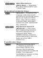
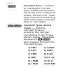
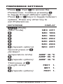
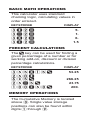
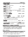
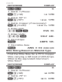
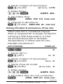
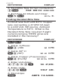
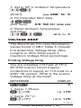
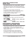
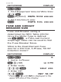
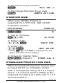
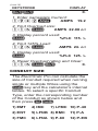
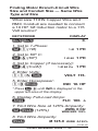
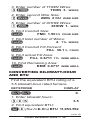
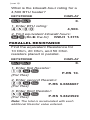
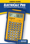
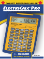
ELECTRICALC® PRO The ElectriCalc ® Pro is an invaluable calculator for today’s busy electrical professional. It has intuitively labeled “electrical keys” and conforms to 1996 through 2011 and future National Electrical Codes. The most common NEC tables are now at your fingertips! The ElectriCalc ® Pro instantly solves for: • Volts, Amps, Volt-Amps, Watts, PF%, and EFF% • • Cu and Al Wire Sizes • Voltage Drop Wire Sizes, and Lengths • • • • • • • Kilowatt hours and BTU’s Parallel and Derated Wire Sizes Parallel Resistance Grounding Conductors Motor FLC Fuse/Breaker Sizes Conduit Sizes And much more! Pocket Reference Guide — 1 Table of Contents GETTING STARTED........................... 4 KEY DEFINITIONS...................................4 Basic Function Keys ..............................4 Mode Set-up Keys..................................6 Electrical Keys........................................6 Motor Keys..............................................8 Wire Sizing Keys.....................................8 Voltage Drop Keys..................................9 Grounding Conductor Keys...................10 Fuse/Breaker Keys...............................10 Conduit Sizing Keys.............................. 11 PREFERENCE SETTINGS.....................13 BASIC MATH OPERATIONS.............. 14 PERCENT CALCULATIONS............... 14 MEMORY OPERATIONS........................14 Using M+...............................................15 Using Memory Storage Keys (M1- M9)...............................................15 using the electricalc pro ....... 15 KIRCHHOFF’S LAW...............................15 Finding Voltage.....................................16 Finding Amps........................................16 Finding Volt-Amps.................................17 Finding kW Rating ................................17 OHM’S LAW............................................18 Finding Volts.........................................18 Finding Amps........................................18 Finding Resistance (Ohms)..................19 MOTOR functions.............................20 Finding Full-Load Current.....................20 Finding Motor Wire Size .......................20 AMPACITY WIRE SIZING.......................21 Wire Sizing............................................21 Wire Sizing Based on Material Type.......22 Sizing Parallel Conductors....................23 Finding Derated Wire Size....................24 VOLTAGE DROP....................................25 Finding Voltage Drop............................25 Finding Voltage Drop Wire Size............26 Finding Voltage Drop Distance.............27 Finding Voltage Drop Resistance..........28 GROUND CONDUCTOR WIRE SIZE..............................................29 EQUIPMENT GROUNDING COUNDUCTOR WIRE SIZE...................29 FUSE AND CIRCUIT BREAKER SIZE......................................30 STARTER SIZE.......................................31 OVERLOAD PROTECTION SIZE...........31 CONDUIT SIZE.......................................32 Finding Motor Branch-Circuit Wire Size and Conduit Size — Same Wire Type and Size....................33 Finding Conduit Size — Multiple Conductors, Different Wire Sizes and Types.............................................34 CONVERTING KILOWATT-HOUR AND BTU................................................35 PARALLEL RESISTANCE.......................36 APPENDIX A — DEFAULT SETTINGS........................... 37 APPENDIX B — CARE INSTRUCTIONS........................ 38 APPENDIX C — ACCURACY/ERRORS, AUTO SHUT-OFF, BATTERIES, RESET......... 39 Repair and Return......................... 42 Pocket Reference Guide — 3 GETTING STARTED KEY DEFINITIONS Basic Function Keys On/Clear Key — Turns on power, clears the last entry and clears all temporary values. Off — Turns all power off. Arithmetic operation keys. - and Keys used for entering numbers. Second Function — Used to access secondary functions. Store — Stores values. - Storage Registers — Store values in Memory. Recall — Used to recall stored values and settings. Memory Clear — Clears M+ and displays total. M+ — Adds value to Accumulative Memory. Memory Recall — Displays the value saved in M+. Memory Clear (M-R/C) — Clears M+ without changing current display. Percentage — Standard % function. x 2 — Squares the value on the display. Backspace Function — Used to delete entries one keystroke at a time. ! — Calculates the Square Root of the displayed value. 1/x — Finds the Reciprocal of a number. Clear All — Reset all settings, other than preferences to default. +/– — Toggles sign of value. Pi — Displays value of (3.1415927). Pocket Reference Guide — 5 Mode Set-up Keys Prefs — Use to define calculator modes. 1Ø — Sets calculator to Single-Phase mode. 3Ø — Sets calculator to Three-Phase mode. Amb° — Enters ambient temperature for finding Wire Sizes. Copper/Aluminum (Cu/Al) — Toggles between Copper and Aluminum Wire. Free Air (FrAir) — Sets calculator to Free Air mode. 60°C Wire Insulation — Sets to 60°C Wire. 75°C Wire Insulation — Sets to 75°C Wire. 90°C Wire Insulation — Sets to 90°C Wire. Electrical Keys kilo- — Used to identify “kilo-” values. milli- — Used to identify “milli-” values. Amps — Enters or calculates Amps. Volts — Enters or calculates Volts. Volt-Amps — Enters or calculates Volt-Amps. Watts — Enters or calculates Watts. DC Amps (Idc) — Enters or calculates DC Amps. DC Volts (Vdc) — Enters or calculates DC Volts. DC Resistance (R) — Enters or calculates DC Resistance in Ohms. Power Factor (PF%) — Enters or calculates Power Factor. Theoretical Horsepower — Enters or calculates Theoretical Horsepower. Efficiency (Eff %) — Enters or calculates the Power Efficiencies. (cont’d) Pocket Reference Guide — 7 (cont’d) Kw-hr ► Btu — Converts Kw-hr to Btu. BTU to Kilowatt–Hours (Btu ► Kw-hr) — Converts Btu to Kw-hr. Parallel Resistance (Par Res) — Calculates total Resistance of Parallel Resistors. Motor Keys Ind/Sync/DC — Toggles between Motor Types. Motor Horsepower — Enters or calculates Motor Horsepower. Starter Size (Starter) — Displays the Starter Size. Wire Sizing Keys Wire Size/Ampacity — Enters or calculates Wire Size. Additional presses show smaller wire size (if Length defined), Ampacity, Circular Mils, and referenced table. 125% Ampacity — Used to calculate Wire Size using 125% of Amps. Also shows Ampacity, Circular Mils and NEC table reference with repeated presses. Parallel Size — Provides Wire Sizes using Parallel Conductors. A second press displays the Ampacity. Derated Wire Size (D/R Size) — Calculates Derated Wire Sizes given a number of wires in the raceway. Also shows Adjusted Ampacity, Deration Factor and NEC table reference. Voltage Drop Keys Percent Voltage Drop — Toggles between Actual Voltage Drop and Percent Voltage Drop with repeated presses. Length — Enters or calculates the Length used for Voltage Drop. (cont’d) Pocket Reference Guide — 9 (cont’d) Wire Resistance (Wire Res) — Displays the Wire Resistance per 1,000 Feet. Grounding Conductor Keys Ground — Displays the Copper and Aluminum grounding electrode sizes given an entered Wire Size. Also shows Wire Circular Mils and NEC reference with additional key presses. Equipment Ground (EqGrnd) — Provides the Copper Equipment Ground size given an entered Wire Size. Additional key presses show Aluminum Ground Size and the NEC reference. Fuse/Breaker Keys Overload Protection — Enters a percent Overload Factor and shows the Overload required based on stored Amps. The percent multiplier is shown on the second key press. Motor Type (M-Type) — Displays the current Motor Type for use with Breaker/Fuse sizing. Additional presses toggle between Motor Types. Dual Element Fuse Single Element Fuse (SEFuse) Inverse Time Breaker Instantaneous Trip Circuit Breaker (InsTrip) — Displays the minimum Amp rating and percent multipier. Conduit Sizing Keys , , Number of Wires — Used to enter or calculate the Number of Wires in a raceway and calculate Wire Area. Also shows total Number of Wires and the total area of all wires entered. (cont’d) Pocket Reference Guide — 11 (cont’d) Conduit Size — Enters or calculates Conduit Size. Additional presses show the total number of Wires, Percent Fill, Total Wire Area and remaining Wire Area when Conduit Size is calculated. Conduit Type (Cond Type) — Defines Conduit Type by entering the number correlating to the Types shown below. Repeated presses of also toggles through the Conduit Types. 1) EMT 7) LFMC 2) ENT 8) RMC 3) FMC 9) P-80 4) IMC 10) P-40 5) LFNB 11) P-A 6) LFNA 12) P-EB PREFERENCE SETTINGS Press , then to access the Preferences. Continue pressing to toggle through different settings. Press or keys to toggle between options. Press any other key to exit Preferences. KEYSTROKE (Prefs) (NEC Code) (repeats options) Second press of : (Ambient Temperature Units) (repeats options) Third press of : (Length Units) (repeats options) DISPLAY NEC NEC NEC NEC NEC NEC NEC 2011 1996 1999 2002 2005 2008 2011 AMBº 30. ºC AMBº 86. ºC AMBº 30. ºC FEET 1. MET 1. FEET 1. Pocket Reference Guide — 13 basic math operations This calculator uses standard chaining logic, calculating values in order entered. KEYSTROKE DISPLAY 5. 1. 6. 1.5 percent calculations The key can be used for finding a given percentage of a number or for working add-on, discount or division percentage calculations. KEYSTROKE DISPLAY 53.25 266.25 23.75 200. MEMORY OPERATIONS The Cumulative Memory is located above . Single value storage positions can also be found within digits 1 through 9. Using M+ KEYSTROKE DISPLAY 1. Add to Memory: (M+) (M+) M+ 355. & M+ –255. & 2. Recall Total: TTL 100. & AVG 50. & CNT 2. & 3. Display/Clear Memory: 100. Using Memory Storage Keys (M1- M9) KEYSTROKE DISPLAY M-1 175. 0. M-1 175. using the electricalc pro KIRCHHOFF’S LAW The ElectriCalc Pro can easily find Volts, Amps, VA, Watts, HP (theoretical), Efficiency and Power Factor. Pocket Reference Guide — 15 Finding Voltage Find the Voltage supply to a 1Ø load drawing 14,605 VA and 115 Amps. KEYSTROKE DISPLAY 0. 1. Set to 1-Phase: (1Ø) 2. Enter VA: 1Ø 3. Enter Amps: 4. Solve for Volts: 1 PH VA 14,605. AMPS 115. VOLT 127. Finding Amps What is the current for a load drawing 8,250 VA on a 240V, 3Ø circuit? KEYSTROKE DISPLAY 0. 1. Set to 3-Phase: (3Ø) 2. Enter VA: 3. Enter Volts: 4. Solve for Amps: 3Ø 3 PH VA 8,250. VOLT 240. AMPS 19.846416 Finding Volt-Amps What is the VA rating for a 120 Volt, 22 Amp, 1Ø circuit? KEYSTROKE DISPLAY 0. 1. Set to 1-Phase: (1Ø) 2. Enter Volts: 3. Enter Amps: 4. Solve for Volt-Amps: 1Ø 1 PH VOLT 120. AMPS 22. VA 2,640. Finding kW Rating What’s the kW rating for a 90 Amp, 208V, 3Ø boiler with 100% Power Factor? KEYSTROKE DISPLAY 0. 1. Set to 3-Phase: (3Ø) 3Ø 3 PH 2. Set Power Factor: (PF%) PF% 100. 3. Enter Amps: AMPS 90. (cont’d) Pocket Reference Guide — 17 (cont’d) KEYSTROKE 4. Enter Volts: 5. Solve for kW: DISPLAY VOLT 208. KW 32.423991 OHM’S LAW The ElectriCalc Pro uses Ohm’s Law solve for DC Voltage, Current, or Resistance. Finding Volts The Current in a circuit is 0.0125 Amps, and the total Resistance is 480 Ohms. Find the Voltage. KEYSTROKE DISPLAY 0. 1. Enter Current: (Idc) Idc 0.0125 A 2. Enter Resistance: (R) 3. Find Voltage: (Vdc) OHMS 480. Vdc 6. V Finding Amps A 120k electrical resistor is plugged into a 12 volt circuit. Find the Current. KEYSTROKE DISPLAY 0. 1. Enter Resistance: (R) KOHM 120. 2. Enter Voltage: (Vdc) Vdc 12. V 3. Find Current: (Idc) Idc 0.0001 A Finding Resistance (Ohms) An electrical circuit operating at 240 Volts has a Current of 14.6 Amperes. Find the total Resistance. KEYSTROKE DISPLAY 0. 1. Enter Voltage: (Vdc) Vdc 240. V Idc 14.6 A 2. Enter Current: (Idc) 3. Find Resistance: (R) OHMS 16.438356 Pocket Reference Guide — 19 MOTOR functions The ElectriCalc Pro can calculate the Full-Load Current (Amps) of a motor, based on Phase, Voltage and Motor (Synchronous, Induction, or DC) Horsepower using NEC Tables 430.247, 430.248 and 430.250. Finding Full-Load Current A 2 HP Induction motor operates on 230 Volt, Single-Phase power. What is the Full-Load Current for this motor? KEYSTROKE DISPLAY 0. 1. Set to 1-Phase: (1Ø) 2. Enter Volts: 3. Enter HP: 1Ø 1 PH VOLT 230. IND* 2. HP * Press until IND is displayed in the upper left area of the display. 4. Find Full-Load Current: FLC 12. A Finding Motor Wire Size Find the Wire Size required to connect a continuous run, 3Ø, 10 HP Induction motor into a 230V circuit. KEYSTROKE DISPLAY 0. 1. Set to 3-Phase: (3Ø) 2. Set to 60º C: (60º) 3Ø 3 PH 3Ø 60 3 PH 3. Set to Copper (if necessary): (Cu/Al) 3Ø 60 Cu 3 PH 4. Enter Volts: VOLT 230. 5. Enter HP: 10 IND* 10. HP * Press until IND is displayed in the upper left area of the display. 6. Find Full-Load Current: FLC 28. A 7. Find 125% Ampacity Wire Size: AWG 8 CU (125%) WIRE SIZE 125% AMPACITY WIRE SIZING Wire Sizing is based on Ampacity requirements used in NEC Tables 310.15(B)(16) and 310.15(B)(17). Wire Sizing Wiring is being installed for a 240V, 1Ø system rated at 30 kVA. What is the 60° C Copper Wire Size? (cont’d) Pocket Reference Guide — 21 (cont’d) KEYSTROKE DISPLAY 0. 1. Set to 1-Phase: (1Ø) 2. Set to 60º C: (60º) 1Ø 1 PH 1 Ø 60 1 PH 3. Set to Copper (if necessary): (Cu/Al) 1 Ø 60 Cu 1 PH 4. Enter kVA: KVA 30. 5. Enter Volts: 6. Find Amps: VOLT 240. AMPS 125. 7. Find Wire Size: AWG 0 CU WIRE SIZE Wire Sizing Based on Material Type Find the Wire Size for a 75°C Copper Wire carrying a 3Ø load of 265 Amps. What is the equivalent Aluminum Wire Size? KEYSTROKE DISPLAY 0. 1. Set to 3-Phase: (3Ø) 2. Set to 75º C: (75º) 3Ø 3 PH 3Ø 75 3 PH 3. Set to Copper (if necessary): (Cu/Al) 3Ø 75 Cu 3 PH 4. Enter Amps: AMPS 265. 5. Find Wire Size: AWG 300 CU WIRE SIZE 6. Change to Aluminum: (Cu/Al) AWG 400 AL WIRE SIZE Sizing Parallel Conductors (Free Air) What size 60°C insulated Copper Wire is required for a single conductor carrying a 500 Amp load in a Free Air environment (30°C Ambient Temperature.)? What size for two Parallel conductors? KEYSTROKE DISPLAY 0. 1. Set to 60º C: (60º) 60 0. 2. Set to Copper (if necessary): (Cu/Al) 60 Cu 0. 3. Set to Free Air mode: (FrAir) 4. Enter Amps: 60 Cu FrAir 0. AMPS 500. 5. Find Wire Size for one conductor: AWG 500 CU WIRE SIZE (cont’d) Pocket Reference Guide — 23 (cont’d) KEYSTROKE DISPLAY 6. Find Wire Size for two conductors: PAR 000 CU WIRE SIZE 7. Exit Free Air Mode and Clear: 60 Cu 0. Finding Derated Wire Size A circuit was built with 60°C Copper wire connecting a 47,650 VA load to a 240 Volt, 3Ø source. Ambient Temperature is 50°C. What is the Derated Wire Size required if eight current-carrying THHN wires are installed in the raceway? KEYSTROKE DISPLAY 0. 1. Set to 3-Phase: (3Ø) 2. Set to 60º C: (60º) 3Ø 3 PH 3Ø 60 3 PH 3. Set to Copper (if necessary): (Cu/Al) 3Ø 60 Cu 3 PH 4. Enter Volt-Amps: 5. Enter Volts: 6. Find Amps: A VA 47,650. VOLT 240. AMPS 114.62808. 7. Set to 50º C Ambient Temperature: (Ambº) Amb AMB° 50. ºC 8. Find Derated Wire Size: (D/R Size) D/R 500 CU WIRE SIZE 9. Reset Ambient Temperature and Clear: 3Ø 60 Cu 0. VOLTAGE DROP The ElectriCalc Pro uses Resistance values found in NEC Table 8 Chapter 9 to determine Voltage Drop, Wire Lengths or Wire Sizes given a maximum Voltage Drop percentage. Finding Voltage Drop You are installing 175 Feet of 75°C, #8 THW branch circuit Copper conductors to supply an 11A load on a 208V 1Ø system. What is the source Voltage Drop at the load? KEYSTROKE DISPLAY 0. 1. Set to 1-Phase: (1Ø) 2. Set to 75 º C: (75º) 1Ø 1 PH 1 Ø 75 1 PH (cont’d) Pocket Reference Guide — 25 (cont’d) KEYSTROKE DISPLAY 3. Set to Copper (if necessary): (Cu/Al) 1 Ø 75 Cu 1 PH 4. Enter Amps: 5. Enter Volts: 6. Enter Length: AMPS 11. VOLT 208. FEET 175. 7. Enter Wire Size: AWG 8 CU 8. Solve Voltage Drop: WIRE SIZE DROP 3.0 V 9. Solve percent Voltage Drop: DROP 1.4 % V Finding Voltage Drop Wire Size A 20 Amp, 3Ø 208 Volt load will be located 175 Feet away from the source. Assuming a 3% allowable Voltage Drop, what is the size of 75°C conductor required for this branch circuit? KEYSTROKE DISPLAY 0. 1. Set to 3-Phase: (3Ø) 2. Set to 75º C: (75º C) 3Ø PH 3Ø 75 3 PH 3. Set to Copper (if necessary): (Cu/Al) 3Ø 75 Cu 3 PH 4. Enter Amps: 5. Enter Volts: 6. Enter Length: AMPS 20. VOLT 208. FEET 175. 7. Enter allowable VD%: DROP 3.0 % 8. Find Wire Size: AWG 8 CU V VD WIRE SIZE Finding Voltage Drop Distance How far from a Three-Phase 240 Volt source can you install a 15 Amp load using 60°C #10 Copper branch circuit conductors? Assume a 3% allowable Voltage Drop. KEYSTROKE DISPLAY 0. 1. Set to 3-Phase: (3Ø) 2 Set to 60º C: (60º) 3Ø 3 PH 3Ø 60 3 PH 3. Set to Copper (if necessary): (Cu/Al) 3Ø 60 Cu 3 PH (cont’d) Pocket Reference Guide — 27 (cont’d) KEYSTROKE DISPLAY 4. Enter Amps: 5. Enter Volts: AMPS 15. VOLT 240. 6. Enter Wire Size: * AWG 10 CU WIRE SIZE 7. Enter 3% allowable Voltage Drop: DROP 3.0 % V 8. Find distance: FEET 234.86987 Finding Voltage Drop Resistance What is the Resistance per 1,000 Ft. of #2 90° C Copper conductor? KEYSTROKE DISPLAY 0. 1. Set to 90º C: (90º) 90 0. 2. Set to Copper (if necessary): (Cu/Al) 90 Cu 0. 3. Enter Wire Size: * AWG 2 CU WIRE SIZE 4. Find Resistance: (Wire Res) OHMS 0.2033993 WIRE GROUND CONDUCTOR WIRE SIZE The ElectriCalc Pro uses NEC Table 250.66 to find the Grounding Electric Conductor Size for an entered Feeder Size. Find the Grounding electrode conductor Wire Size required when a 2/0 Copper service-entrance conductor is being used. KEYSTROKE DISPLAY 0. 1. Enter Wire Size and find Ground Wire Size: 00 GRND 4 CU WIRE SIZE 2. Find Aluminum size: GRND 2 AL WIRE SIZE EQUIPMENT GROUNDING COUNDUCTOR WIRE SIZE The ElectriCalc Pro uses an external amperage to find the Equipment Grounding conductor based on NEC Table 250.122. Find the Equipment Grounding conductor size required when the circuit breaker is rated at 45 Amps. (cont’d) Pocket Reference Guide — 29 (cont’d) KEYSTROKE DISPLAY 0. 1. Find Equipment Ground Wire Size: 45 (EqGrnd) EQPG 10 CU WIRE SIZE 2. Find Aluminum size: EQPG 8 AL WIRE SIZE FUSE AND CIRCUIT BREAKER SIZE Fuse and Breaker sizing is determined by NEC Table 430.52. Once the Motor Type is defined via L , a Full-Load Current amperage value can be used to find the Fuse Breaker Sizes. What is the Dual Element Fuse size for a 230 Volt, 3-Phase, 50 HP Induction motor? KEYSTROKE DISPLAY 0. 1. Set to 3-Phase: (3Ø) 2. Enter Volts: 3. Enter HP: 3Ø 3 PH VOLT 230. IND* 50. HP * Press until IND is displayed in the upper left area of the display. 4. Find Full-Load Current: FLC 130. A 5. Find Dual Element Fuse size: AMPS 227.5 dE STARTER SIZE What size NEMA Starter is required for a 575 Volt, 3Ø, 20 HP Induction motor? KEYSTROKE DISPLAY 0. 1. Set to 3-phase: (3Ø) 2. Enter Volts: 3. Enter HP: 3Ø 3 PH VOLT 575. IND* 20. HP * Press until IND is displayed in the upper left area of the display. 4. Solve for Starter Size: (Starter) STAR SIZE 2 OVERLOAD PROTECTION SIZE What Overload Protection device size is required for an Induction motor with a nameplate rating of 19.2 Amps and a 1.0 service factor? What is the required Overload at 125% (for a 1.15 service factor)? (cont’d) Pocket Reference Guide — 31 (cont’d) KEYSTROKE DISPLAY 0. 1. Enter nameplate Current: AMPS 19.2 2. Find Overload size: AMPS 22.08 o l 3. Display percent used: %FLC 115. % 4. Find 125% Load: AMPS 24. o l 5. Display percent used: %FLC 125. % 6. Reset Overload rating and Clear: 0. CONDUIT SIZE The ElectriCalc Pro can calculate the size of Conduit required when running single or multiple Wires using the key and the calculator’s internal tables. To select a specific Conduit Type, enter the corresponding number of the Conduit as shown below and then press . 1) EMT 4) IMC 2) ENT 5) LFNB 8) RMC 7) LFMC 10) P-40 11) P-A 3) FMC 6) LFNA 9) P-80 12) P-EB Finding Motor Branch-Circuit Wire Size and Conduit Size — Same Wire Type and Size What size THHN Copper Wire and RMC Conduit are needed to connect a 10 HP 1Ø Induction motor to a 115 Volt source? KEYSTROKE DISPLAY 0. 1. Set to 1-Phase: (1Ø) 2. Set to 60º C: (60º) 1Ø 1 PH 1 Ø 60 1 PH 3. Set to Copper (if necessary): (Cu/Al) 1 Ø 60 Cu 1 PH 4. Enter Volts: VOLT 115. 5. Enter Horsepower: IND 10. HP * Press until IND is displayed in the upper left area of the display. 6. Display Full-Load Amps: FLC 100. A 7. Find Wire Size at 125% Ampacity: AWG 0 CU (125%) WIRE SIZE 125% 8. Find Wire Ampacity: Ø 125.0 WIRE A125% (cont’d) Pocket Reference Guide — 33 (cont’d) KEYSTROKE DISPLAY 9. Enter Conduit Type and find Conduit Size: 8S (Cond Type) RMC 1.25 in COND SIZE 10. Find total number of Wires: 2. TTL WIRES 11. Find Conduit Fill Percent: FILL 24.3 % COND 12. Find actual Fill Area: FILL 0.3710 TTL WIRE AREA 13. Find Remaining Area: REM 0.1021 WIRE AREA Finding Conduit Size — Multiple Conductors, Different Wire Sizes and Types Three 1/0 THWN conductors and one #2 XHHW conductor are to connect to a panel board using a single Conduit. What is Conduit Size needed and actual Fill Area? KEYSTROKE DISPLAY 0. 1. Enter Conduit Type: (Cond Type) FMC nonE 2. Enter first Wire Size: * AWG 0 CU COND WIRE SIZE 3. Enter number of THWN Wires: THHN 3. WIRES 4. Enter second Wire Size: * AWG 2 CU WIRE SIZE 5. Enter number of XHHW Wires: XHHW 1. WIRE 6. Find Conduit Size: FMC 1.50 in COND SIZE 7. Find total number of Wires: 4. TTL WIRES 8. Find Conduit Fill Percent: FILL 36.1 % COND 9. Find actual Fill Area: FILL 0.6711 TTL WIRE AREA 10. Find Remaining Area: REM 0.0717 WIRE AREA CONVERTING KILOWATT-HOUR AND BTU Find the equivalent BTU rating of a 3.5 kilowatt-hour rated furnace. KEYSTROKE DISPLAY 1. Enter kilowatt hours: 0. 3.5 2. Find equivalent BTU: (Kw-hr►Btu) BTU 11,953.552 (cont’d) Pocket Reference Guide — 35 (cont’d) What is the kilowatt-hour rating for a 4,500 BTU heater? KEYSTROKE DISPLAY 0. 1. Enter BTU rating: 4,500. 2. Find equivalent kilowatt hours: (Btu►Kw-hr) KW-H 1.3176 PARALLEL RESISTANCE Find the equivalent Resistance for 10 Ohm, 20 Ohm, and 50 Ohm resistors placed in parallel. KEYSTROKE DISPLAY 0. 1. Enter first Resistor: P-RS 10. (Par Res) 2. Enter second Resistor: (Par Res) P-RS 6.6666667 3. Enter third Resistor: (Par Res) P-RS 5.8823529 Note: The total is recalculated with each additional Resistor value entered. APPENDIX A — DEFAULT SETTINGS After a Clear All ( ), your calculator will return to the following settings: STORED VALUES Insulation Rating Wire Material Phase Ambient Temperature Volts Voltage Drop % Power Factor % Efficiency % Motor Type Conduit Type Fuse/Breaker Motor Type Overload FLC% Free Air Mode* DEFAULT VALUE 60º C Copper 3Ø 30º C (86º F) 240V 3% 100% 100% Induction EMT Squirrel Cage non Design E 115% Off * This setting will also return to its default upon turning the calculator off and back on. If you replace your batteries or perform a Full Reset* (Press O, hold down x and press o) your calculator will return to the following settings (in addition to those listed above): (cont’d) Pocket Reference Guide — 37 (cont’d) Preference Settings DEFAULT VALUE NEC Code 2011 Temperature Units °C Length Units FEET * Depressing the Reset button located above the C key will also perform a Full Reset. APPENDIX B — CARE INSTRUCTIONS Please follow the guidelines listed in this section for proper care and operation of your calculator. Not following the instructions listed below may result in damage not covered by your warranty. Refer to the Warranty section on page 61 of the User's Guide for more details.. Do not expose calculator to temperatures outside the operating temperature range of 32ºF – 104ºF (0ºC – 40ºC). Do not expose calculator to high moisture such as submersion in water, heavy rain, etc. APPENDIX C — ACCURACY/ERRORS, AUTO SHUT-OFF, BATTERIES, RESET Accuracy/Errors Accuracy/Display Capacity — Your calculator has an eight-digit display. You may enter or calculate values up to 99,999,999. Each calculation is carried out internally to 12 digits. Errors — When an incorrect entry is made, or the answer is beyond the range of the calculator, an error message will display. To clear an error condition, press the button once. At this point, you can determine what caused the error and re-key the problem. Error Codes DISPLAY ERROR TYPE OFLO Overflow; answer too large to display ENT Error Invalid entry POWR Error Power Factor (PF) or Efficiency (EFF) calculated above 100% (cont’d) Pocket Reference Guide — 39 (cont’d) nonE Unable to calculate or not available HP Error Invalid Horsepower entry per NEC table FULL Error Entered or calculated more than 15 different Wires Sizes EROM Error Bad EPROM MATH Error Math error (i.e., divide by zero) Auto Shut-Off Your calculator is designed to shut itself off after about 8-12 minutes of non-use. Battery The ElectriCalc Pro uses one CR2016 battery. Should your calculator display become dim or erratic, replace the battery. NOTE: Please use caution when disposing of your old battery as it contains hazardous chemicals. Replacement batteries are available at most discount or electronics stores. You may also call Calculated Industries at 1-775-885-4900 or go to www.calculated.com. Battery Replacement Instructions While the calculator is off, turn the calculator over and use a #1 Phillips screwdriver to remove the battery holder screw located near the center at the top. With the screw removed, pull battery holder out, remove old battery, and slide new battery into holder. The negative side of the battery should be facing you as you insert the battery holder into the calculator. Replace screw using a #1 Phillips screwdriver. Reset If your calculator should ever “lock up,” press Reset — a small hole located below the key — to perform a total reset. Pocket Reference Guide — 41 Repair and Return Return Guidelines 1. Please read the Warranty in the User’s Guide to determine if your Calculated Industries product remains under warranty before calling or returning any device for evaluation or repairs. 2. If your product won’t turn on, check the battery as outlined in the User’s Guide. 3. If you need more assistance, please go to the website listed below. 4. If you believe you need to return your product, please call a Calculated Industries representative between the hours of 7:00am to 4:30pm Pacific Time for additional information and a Return Merchandise Authorization (RMA). Call Toll Free: 1-800-854-8075 Outside USA: 775-885-4900 www.calculated.com/warranty 4840 Hytech Drive Carson City, NV 89706 U.S.A. 1-800-854-8075 Fax: 1-775-885-4949 E-mail: [email protected] www.calculated.com Pocket Reference Guide — 43