1
1
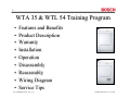
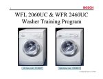
WTA 35 & WTL 54
Dryer Training Program
Vented model - WTA3510UC
702_58300000141665_ara_en_a
Condensation model - WTL5410UC
1st Edition/Revision 3 (4/11/03)
2
WTA 35 & WTL 54 Training Program
•
•
•
•
•
•
•
•
•
Features and Benefits
Product Description
Warranty
Installation
Operation
Disassembly
Reassembly
Wiring Diagram
Service Tips
702_58300000141665_ara_en_a
1st Edition/Revision 3 (4/11/03)
3
Features and Benefits
• Anti-crease feature
• Smooth stainless steel drum - won’t rust & is
gentle to clothes
• Auto-dry with 2 digital moisture sensors and 3
temperature sensors
• Moisture and temperature sensors automatically
determine when laundry is dry, preventing overdrying and damaging clothing.
• Regular/Cotton - 6 settings
• Permanent Press - 5 settings
• Reverse tumble action
• Spanish and French fascia inserts (WTA
3510/WTL 5410)
• UL listed (U.S. & Canada)
702_58300000141665_ara_en_a
1st Edition/Revision 3 (4/11/03)
4
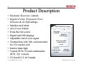
Product Description
• Electronic Duotronic controls
• Regular/Cotton, Permanent Press,
Delicates & Air fluff settings
• Stainless steel drum
• Anti-Crease feature
• Extra-fine lint screen
• Digital and LED displays
• Adjustable end of cycle signal
• Terminal box with 30A cord and outlet
for 15A washer cord
• Interior drum light
• Vented (WTA 35) and condensation
(WTL 54) versions
• UL listed (U.S. & Canada)
702_58300000141665_ara_en_a
Auto or timed dry settings
Electronic
controls
Digital &
LED displays
Easily accessible
extra-fine lint
screen
Vented &
condensation
versions
Interior
drum light
1st Edition/Revision 3 (4/11/03)
5
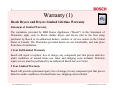
Warranty (1)
Bosch Dryers and Dryers Limited Lifetime Warranty
Statement of Limited Warranty
The warranties provided by BSH Home Appliances ("Bosch") in this Statement of
Warranties apply only to Bosch clothes dryers and dryers sold to the first using
purchaser by Bosch or its authorized dealers, retailers or service centers in the United
States or Canada. The Warranties provided herein are not transferable, and take place
from date of installation.
1 Year Full Limited Warranty
Bosch will repair or replace, free of charge, any component part that proves defective
under conditions of normal home use, labor and shipping costs included. Warranty
repair service must be performed by an authorized Bosch Service Center.
2 Year Limited Warranty
Bosch will provide replacement parts, free of charge, for any component part that proves
defective under conditions of normal home use, shipping costs included.
702_58300000141665_ara_en_a
1st Edition/Revision 3 (4/11/03)
6
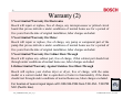
Warranty (2)
5 Year Limited Warranty On Electronics
Bosch will repair or replace, free of charge, any microprocessor or printed circuit
board that proves defective under conditions of normal home use for a period of
five years from the date of original installation, labor charges excluded.
5 Year Limited Warranty On Motor
Bosch will repair or replace, free of charge, any pump or component part of the
pump that proves defective under conditions of normal home use for a period of
five years from the date of original installation, labor charges excluded.
5 Year Limited Warranty On Cabinet Rust-Through
Bosch will replace any cabinet part, free of charge, if that cabinet part should rust
through under conditions of normal home use, labor charges excluded.
Lifetime Limited Warranty Against Stainless Steel Rust-Through
Bosch will replace your clothes dryer or dryer, free of charge, with the same
model or a current model that is equivalent or better in functionality if the drum
should rust through under conditions of normal home use, labor charges excluded.
For location of nearest repair depot call 1-800-944-2904 from 5:00 AM - 5:00 PM
M-F (Pacific time)
702_58300000141665_ara_en_a
1st Edition/Revision 3 (4/11/03)
7
Warranty -- Serial # Label
The serial # label, located on the rear of the dryer (on the right
side), shows necessary warranty information.
Serial #
label
NOTE: There is another label
on the inside of the door, but it
doesn’t show the serial #.
• Model # - “WTA3500UC/13”.
•
Serial # - “FD 8104”. To find when the product type
was built, add 20 to the 1st two digits to get the year
(81 + 20 = 101 Æ product type was built in 2001).
The last two digits show the month (04 = April).
702_58300000141665_ara_en_a
Factory serial # - Can convert
factory serial # to FD # for
warranty use. 1st 2 digits show
factory # (47 = Nauen), 3rd digit
shows year (1 = 2001), 4th & 5th
digits show month built (04 =
April). So, serial # starting with
“47104…0008397” = dryer built @
Nauen with FD 8104 30108.
1st Edition/Revision 3 (4/11/03)
8
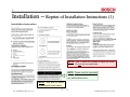
Installation -- Reprint of Installation Instructions (1)
NOTE: Use 4” metal duct (flexible or rigid) with these
dryers. Do not use non-metal duct.
NOTE: Dryers must be grounded
to reduce the risk of shock should
any malfunctions occur.
NOTE: Be sure to follow
all national & local codes.
702_58300000141665_ara_en_a
1st Edition/Revision 3 (4/11/03)
9
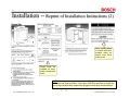
Installation -- Reprint of Installation Instructions (2)
Don’t install dryers
in closets with solid
wooden doors as
dryers must have
make-up air.
Dryers must be
installed on level,
solidly constructed
floors.
HINT: Washers and dryers are both rated 15A @ 240VAC. Washers have
15A cords and plugs provided. Dryers have 30A cords provided to handle the
power requirements when washers are plugged into the dryer terminal boxes.
702_58300000141665_ara_en_a
1st Edition/Revision 3 (4/11/03)
10
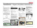
Installation -- Reprint of Installation Instructions (3)
HINT:
Use as few
elbows as possible.
702_58300000141665_ara_en_a
HINT: Don’t exceed
maximum duct lengths
shown in Table 1.
1st Edition/Revision 3 (4/11/03)
11
Installation -- Reprint of Installation Instructions (4)
4-wire connection
CAUTION: Dryers must
be grounded to reduce
the risk of shock.
702_58300000141665_ara_en_a
HINT: The dryer uses a
NEMA 10-30P 240V,
30A, 4-wire plug, which
mates to a NEMA 1030R outlet (receptacle).
CAUTION: When moving
a dryer, screw in the feet
(leveling legs) first so they
won’t be damaged.
1st Edition/Revision 3 (4/11/03)
12
Installation -- Reprint of Installation Instructions (5)
CAUTION: When moving a dryer, screw in the feet
(leveling legs) first so they won’t be damaged.
702_58300000141665_ara_en_a
1st Edition/Revision 3 (4/11/03)
13
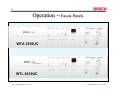
Operation -- Fascia Panels
WTA 3510UC
WTL 5410UC
702_58300000141665_ara_en_a
1st Edition/Revision 3 (4/11/03)
14
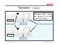
Operation -- Controls
Both have Regular/Cotton,
Permanent Press, Timed
Dry, Heated Dry, Air Fluff
& Delicates settings.
WTA 3510UC
Digital Display
Timed Cycles
Selector knob
Auto-Cycles Selector knob
WTL 5410UC
Timed Cycles
Selector knob
702_58300000141665_ara_en_a
1st Edition/Revision 3 (4/11/03)
15
Operation -- Cleaning Lint Filter
Lint Filter
The lint filter should be cleaned after each use or If the Lint Filter light becomes illuminated and the
buzzer sounds during operation of the dryer:
1. Immediately stop the dryer by depressing the On/Off button.
2. Depress the Door button and open the door.
3. Remove the filter.
4. Clean the filter.
5. Replace the filter.
6. Let the dryer cool down.
7. Close the door.
8. Press the Start button to restart the dryer.
702_58300000141665_ara_en_a
1st Edition/Revision 3 (4/11/03)
16
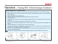
Operation -- Cleaning WTL 54 Heat Exchanger (Condenser)
Heat Exchanger (WTL 54 models only)
The heat exchanger should be cleaned 3–4 times a year; more often if used frequently. To clean the heat exchanger:
1. With the dryer turned off and disconnected from the electrical supply. Disconnect the power cord by grasping the
plug, not the cord.
2. Depress the Door button and open the door.
3. Press the button for opening the heat exchanger/inlet panel, as shown in Figure 6.
4. Open the panel fully.
5. Turn the retainers on each side of the heat exchanger towards each other, in the direction of the arrows as shown
in Figure 7.
6. Remove the heat exchanger by slowly pulling it forward and out of the dryer.
7. Clean the heat exchanger thoroughly with water. Allow the water to run freely through the heat exchanger. See
Figure 8.
8. Allow heat exchanger to dry thoroughly before reinserting into the dryer.
9. Once the heat exchanger is completely dry, reinsert it into the dryer. The handle must be underneath the heat
exchanger. Turn the retainers back to their original position.
10. Close the heat exchanger/inlet panel by pressing firmly on both the upper left and right hand sides, as shown in
Figure 9, until it snaps into place.
Note: The dryer door can only be closed if the heat exchanger/inlet panel is properly closed and locked in place.
702_58300000141665_ara_en_a
1st Edition/Revision 3 (4/11/03)
17
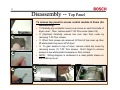
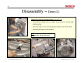
Disassembly -- Top Panel
To remove top panel to access control module & frame (for
disassembly):
1
2
2
702_58300000141665_ara_en_a
• c Carefully pry out plastic covers over screw on each front side of
dryer cover. Then, remove each T-20 Torx screw (total of 2).
• d (Optional) Carefully remove two rear clips from cover by
removing T-20 Torx screws.
• e When front screws are removed, tilt front of top cover up, then
lift white plastic top cover off of dryer.
• f To gain access to top of dryer, remove metal top cover by
removing seven (7) T-20 Torx screws. Don’t forget to remove
screws in two white plastic bumpers on front corners.
• NOTE: Wiring diagram is contained in a clear plastic sleeve on
the metal top cover.
3
4
4
1st Edition/Revision 3 (4/11/03)
18
Disassembly -- Fascia Panel
To remove fascia panel to access display module &
frame (for disassembly), carefully pry panel toward front
of dryer and lift panel up. Don’t break plastic tabs.
NOTE: Also need
to separate wire
harness & door
latch cable from
front
panel
&
display module.
702_58300000141665_ara_en_a
1st Edition/Revision 3 (4/11/03)
19
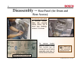
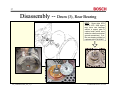
Disassembly -- Rear Panel (for Drum and
Rear Access)
To remove rear panel
to access heater,
NTC R2, Hi-Limit
safety cutout, fan &
drum rear bearing),
remove 12 screws.
To remove heater,
remove heater cover,
then remove two (2)
screws at top of heater
assembly and one (1)
screw at wire harness.
NOTE: Heaters cycle
on and off as needed
to keep temperatures
at appropriate levels.
Heater cover with ratings
702_58300000141665_ara_en_a
1st Edition/Revision 3 (4/11/03)
20
Disassembly -- Front Panel (1) (for Drum and
Front Access)
Removing front panel screws
Removing door hinges
.
.
.
.
.
702_58300000141665_ara_en_a
.
.
.
HINT: Remove front panel to
access drum, display module,
R3 NTC & door latch.
To remove front panel, remove three (3) T-20
Torx screws @ top of panel and five (5) T-20
Torx screws around door face frame. See red
dots for screw locations.
HINT: Carefully pry out white
cap to access T-20 Torx
screw underneath door.
1st Edition/Revision 3 (4/11/03)
21
Disassembly -- Front Panel (2) (for Drum and
Front Access)
The door face frame
lifts up and out with
the NTC attached -disconnect the NTC
connector.
NTC R3 in bottom of door face frame
Removing
door latch
HINT: To remove door
latch from front panel,
remove two (2) T-10
Torx screws.
HINT: Remove door latch and disconnect
NTC R3 wire harness before removing
door face frame (from front panel).
702_58300000141665_ara_en_a
1st Edition/Revision 3 (4/11/03)
22
Disassembly -- Side Panels (for Drum and
Right Side Access)
To remove side panels to
access drum & drive
motor:
Unscrewing
side panel
screws
Removing
side panels
• Remove four (4) T-20
Torx panel screws from
rear of dryer.
• Remove one (1) T-20
Torx screw from top front
of dryer.
• Then carefully lift panels
up and out.
HINT: Remove right side panel to
access drum drive motor, belts/pulleys,
heater connector & motor capacitor.
702_58300000141665_ara_en_a
1st Edition/Revision 3 (4/11/03)
23
Disassembly -- Frame (1)
To access the drum, the frame must be partially disassembled.
TO DISASSEMBLE FRAME (to access
drum):
• c Remove top, fascia & side panels (with
1
To remove
inner frame,
lift it up and
out.
door).
•
d Remove drum drive belt.
•
See next page for rest of procedure.
Frame with fascia, front & side panels removed.
To remove belt,
remove
motor
tensioning spring,
then slide belt off
of front of drum.
1
702_58300000141665_ara_en_a
2
1st Edition/Revision 3 (4/11/03)
24
Disassembly -- Frame (2)
3
TO DISASSEMBLE FRAME to
access drum (continued):
• e After the side panels have
been removed, remove one (1)
long T-20 Torx screw from the
front of the base on each side
(total of 2 screws).
•
f Remove front frame rail
screws from front of dryer.
•
4
702_58300000141665_ara_en_a
g Remove front frame screws
from top of dryer.
5
1st Edition/Revision 3 (4/11/03)
25
Disassembly -- Drum (1)
REMOVING DRUM FROM FRAME:
• If not done already, disconnect wire harnesses hindering
removing drum and place them out of the way. Leave the
control module (with wire harnesses) mounted to the side
frame.
• Lift out front panel from frame.
• Remove front frame rails.
702_58300000141665_ara_en_a
1st Edition/Revision 3 (4/11/03)
26
Disassembly -- Drum (2)
REMOVING DRUM FROM FRAME (continued):
• If not done already, remove heater (rear) cover to access rear
drum bearing.
• Unscrew main nut on rear bearing to release drum from frame.
• Carefully lift drum out from frame.
HINT: Use a 13mm socket or wrench on
the main nut on the rear of the drum.
702_58300000141665_ara_en_a
1st Edition/Revision 3 (4/11/03)
27
Disassembly -- Drum (3), Rear Bearing
HINT:
Some older WTA
3500 & WTL 5400 dryers
may have rear bearings
without a copper plate &
carbon brush (which were
added to enhance electrical
ground connections). If so,
the rear bearing should be
replaced with kit # 183897.
702_58300000141665_ara_en_a
1st Edition/Revision 3 (4/11/03)
28
Disassembly -- WTA 35 Drum Drive Motor
To disassemble drum drive motor:
•
Remove heater cover on rear of dryer.
Remove right side panel.
•
Release belt tension spring and small belt.
•
Using a 13mm wrench or socket on fan blade
and an adjustable wrench on pulley, loosen and
remove fan blade from motor shaft.
•
Remove (“horseshoe”) drum motor clamp by
removing two screws.
•
Remove belt tensioning mount by removing two
screws.
•
Disconnect terminal connector from motor.
•
Remove motor from dryer.
702_58300000141665_ara_en_a
1st Edition/Revision 3 (4/11/03)
29
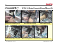
Disassembly -- WTL 54 Drain Pump & Drum Motor (1)
WTA 35
shown
WTA 35
shown
WTA 35
shown
Remove rear cover & right side panel
HINT: Carefully remove rear
cover to avoid damaging
gasket.
Bring a # 167651
gasket for any WTL 54 repair
in case gasket gets damaged.
702_58300000141665_ara_en_a
Push latch to unhook spring.
1st Edition/Revision 3 (4/11/03)
30
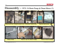
Disassembly -- WTL 54 Drain Pump & Drum Motor (2)
Disconnect drain pump wires
Drum motor clamp removed
702_58300000141665_ara_en_a
Slide drive belt off pulley
Remove spring holder
Pull out motor clamp
Unscrew pump cover screw
1st Edition/Revision 3 (4/11/03)
31
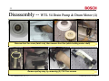
Disassembly -- WTL 54 Drain Pump & Drum Motor (3)
Disconnect hose Remove pump cover Disconnect motor wires
Remove float
702_58300000141665_ara_en_a
Remove rear fan (13mm socket)
Remove drain pump
Remove front insulation
1st Edition/Revision 3 (4/11/03)
32
Disassembly -- WTL 54 Drain Pump & Drum Motor (4)
Remove front fan cover (twist ccw), then remove front fan (while holding motor shaft)
Remove pulley assy. by removing (2) T-20 Torx screws
702_58300000141665_ara_en_a
1st Edition/Revision 3 (4/11/03)
33
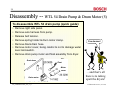
Disassembly -- WTL 54 Drain Pump & Drum Motor (5)
HINT: Without removing drum, pulley
assy. screws access is tight. Use a
ratcheting screwdriver for tight locations.
Exposed drum drive motor
Remove drum motor
Push drum drive motor
toward rear of dryer.
HINT: If necessary, pry out motors
carefully (using wood or a tool
which won’t damage the dryer).
Disassembled drum drive motor
702_58300000141665_ara_en_a
You’re done!!
1st Edition/Revision 3 (4/11/03)
34
Disassembly -- WTL 54 Drain Pump & Drum Motor (5)
To disassemble WTL 54 drain pump (quick guide):
• Remove right side panel.
• Remove wire harness from pump.
• Release belt tension.
• Remove spring holder & drum motor clamp.
You da man!
• Remove black drain hose.
• Remove motor cover, being careful to not to damage water
level microswitch.
• Remove drain pump motor and float assembly from dryer.
Drain hose
Float
Motor
cover
Drain motor
702_58300000141665_ara_en_a
…and that’s all
there is to taking
apart the dryers!
1st Edition/Revision 3 (4/11/03)
35
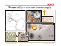
Reassembly -- Rear Main Drum Bearing (1)
HINT:
Make sure rear
bearing nut is tight -- if
not, dryer can squeal
when drum turns.
702_58300000141665_ara_en_a
1st Edition/Revision 3 (4/11/03)
36
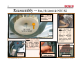
Reassembly -- Rear Main Drum Bearing (2)
HINT: Rear bearing kit #
183897 includes a copper
plate & carbon brush to
enhance electrical ground
connections.
Rear bearing kit # 183897.
HINT:
Some older WTA
3500 & WTL 5400 dryers
may have rear bearings
without a copper plate &
carbon brush (which were
added to enhance electrical
ground connections). If so,
the rear bearing should be
replaced with kit # 183897.
702_58300000141665_ara_en_a
1st Edition/Revision 3 (4/11/03)
37
Reassembly -- Fan, Hi-Limit & NTC R2
HINT: If fan nut
won’t tighten down
adequately, install
a lockwasher.
HINT:
On WTL 54
condensation dryers,
make sure the rear
seal
is
installed
properly to avoid any
moisture
leaking.
Always bring a gasket
when doing any WTL
54 repairs.
NOTE: Hi-Limit (high
temp cutout), located
on heater housing,
trips @ 212ºF (WTA
35) or 248ºF (WTL
54). To reset Hi-Limit,
press red button.
Resetting
Hi-Limit
702_58300000141665_ara_en_a
NTC R2 (on top of
heater housing)
Heater plug
1st Edition/Revision 3 (4/11/03)
38
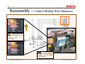
Reassembly -- Control Module Wire Harnesses
OK
HINT: Make sure there
is no gap between the
orange
and
pink
connectors.
Wrong
702_58300000141665_ara_en_a
NOTE:
If the orange
connector isn’t reattached
properly, the E3 heater
won’t come on.
1st Edition/Revision 3 (4/11/03)
39
Reassembly -- Drum Interior Light
3
Plastic
tabs
I’ve seen
the light!
2
1
Remove fascia panel (with display module) to access light,
taking care not to damage panel plastic tabs (photos 1-3).
4
5
6
Remove light cover (located above
door panel next to On/Off & Door
switch assembly).
702_58300000141665_ara_en_a
Pull out light socket (with connectors) and change light bulb.
1st Edition/Revision 3 (4/11/03)
40
Reassembly -- Terminal Box
NOTE: Fuse holders for SC-15 15A fuses
aren’t available and must be bought locally.
702_58300000141665_ara_en_a
1st Edition/Revision 3 (4/11/03)
41
WTA 35/WTL 54 Circuit Diagram
HINT: “Mains” is the
European term for
“power”.
HINT:
This circuit
diagram is used for
WTA 3500UC, WTA
3510UC, WTL 5400UC
& WTL 5410UC dryers.
NOTE: Heaters cycle
on and off as needed
to keep temperatures
at appropriate levels.
(WTL 5400 UC & 5410UC)
702_58300000141665_ara_en_a
1st Edition/Revision 3 (4/11/03)
42
WTA 35 /WTL 54 Wiring Diagram
HINT: “Mains” is the
European term for
“power”.
HINT:
This wiring
diagram is used for
WTA 3500UC, WTA
3510UC, WTL 5400UC
& WTL 5410UC dryers.
(WTL 5400UC & WTL 5410UC)
NOTE: Heaters cycle on and off as needed to keep
temperatures at appropriate levels.
702_58300000141665_ara_en_a
1st Edition/Revision 3 (4/11/03)
43
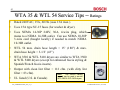
WTA 35 & WTL 54 Service Tips -- Ratings
•
Rated 240VAC, 15A, 60 Hz (uses 13A max.).
•
Uses 15A type SC-15 fuses (for washer & dryer).
•
Uses NEMA 14-30P 240V, 30A, 4-wire plug, which
mates to a NEMA 14-30R outlet. Can use NEMA 10-30P
3-wire cord (bought locally) if needed to match NEMA
10-30R outlet.
•
WTL 54 max. drain hose length = 15’ (180”) & max.
drain hose height = 3-1/2’ (43”).
•
WTA 3510 & WTL 5410 dryers are similar to WTA 3500
& WTL 5400 dryers (except for enhanced fascia styling &
Spanish/French fascia inserts).
•
Output with clean lint filter = 112 cfm. (with dirty lint
filter = 83 cfm).
HINT:
This service training
•
UL listed (U.S. & Canada)
702_58300000141665_ara_en_a
manual can be used to service
WTA 3500 & WTL 5400 dryers.
1st Edition/Revision 3 (4/11/03)
44
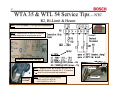
WTA 35 Service Tips -- Drum Drive Motor
Replacing drive belt
HINT: Remove right side panel to access drum drive motor,
belts/pulleys, heater connector & motor capacitor.
702_58300000141665_ara_en_a
WTL 54
WTA 35
1st Edition/Revision 3 (4/11/03)
45
WTL 54 Service Tips -- Drum Drive Motor
Drum drive motors on WTL 54 condensation dryers
are different and are installed differently than WTA 35
vented dryers to avoid water leaking, provide space
for the drain pump and provide a condenser fan.
Motor
capacitor
Moto
r
conn
e ct o
r plu
gs
CAUTION: When installing WTL 54 drum drive motors, be
careful to not damage cover seal to prevent water leakage.
HINT: Remove right side panel to access drum drive motor,
belts/pulleys, heater connector & motor capacitor.
702_58300000141665_ara_en_a
1st Edition/Revision 3 (4/11/03)
46
WTL 54 Service Tips -- Pump Motor
WTL 54 condensation dryers have drain
pumps to eliminate the condensed water.
HINT: Pump motor resistance
measurement is ~ 110 - 136Ω.
HINT: Remove right side panel to
access pump motor.
702_58300000141665_ara_en_a
Drain hose connection
on right rear of dryer.
1st Edition/Revision 3 (4/11/03)
47
WTA 35 & WTL 54 Service Tips -- NTC
R2, Hi-Limit & Heater
HINT: NTC R2 reads ~ 21 kΩ @ room temperature.
NOTE: Heaters cycle on and off as needed
to keep temperatures at appropriate levels.
Hi-Limit
Heater cover with ratings
E2 = 800W @ 240V (draws ~ 3A)
E3 = 1900W @ 240V (draws ~ 7A)
HINT: Measure heater E3 between terminals 8 & 5
and heater E2 between terminals 8 & 7. If resistance
= ∞, reset Hi-Limit thermostat and remeasure.
Resetting
Hi-Limit
702_58300000141665_ara_en_a
HINT: Hi-Limit (safety cutout) trips @:
• 100ºC (212ºF) for WTA 35
• 120ºC (248ºF) for WTL 54
Top of heater housing
NTC R2
Hi-Limit
1st Edition/Revision 3 (4/11/03)
48
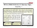
WTA 3500/3510 UC/13 Service Tips -Timed Dry
WTA 3500/3510 UC/13 vented dryers have Timed Dry cycles which use
less energy than WTA 3500 UC/04 - UC/10 dryers (to meet Canadian
energy requirements). These dryers can take longer to dry laundry during
Timed Dry. This doesn’t affect WTL 54 condensation dryers -- they do not
have a reduced heat output during Timed Dry cycles.
The Timed Dry cycles are intended for drying delicates
and hand washables.
When drying cotton and
permanent press fabrics, Auto-cycles (i.e. sensor
controlled drying) should be used. Using Auto-cycles,
WTA 3500/3510 UC/13 vented dryers heat to full
capacity and sense when clothes are dry, drying clothes
quickly and safely.
NOTE:
WTA 3500 UC/04,
UC/08 & UC/10 dryers used
control module # 265677, which
provided full heating during
Timed Dry.
702_58300000141665_ara_en_a
NOTE: WTA 3500 & WTA 3510
UC/13 dryers use control module #
481590, which provides reduced
heating during Timed Dry to meet
Canadian energy requirements.
1st Edition/Revision 3 (4/11/03)
49
WTA 35 Service Tips
-- Whistling Dryers
WTA 3500/3510 vented dryers can
occasionally whistle if one or more of
the vent covers has worked loose or
wasn’t installed securely.
To eliminate whistling from WTA 35 vented
dryers, reattach vent covers to dryers with
silicone caulk. Use a non-adhesive type
which will allow vent covers to be moved at a
later date.
HINT: Use silicone caulk to fasten
vent covers whenever installing or
repairing WTA 35 vented dryers.
702_58300000141665_ara_en_a
1st Edition/Revision 3 (4/11/03)
50
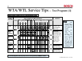
WTA/WTL Service Tips -- Test Program (1)
WTA 35 & WTL 54 dryers have test programs enabling them to selfdiagnose problems, including listing the last fault code.
To enter/exit test program for WTA 35 & WTL 54 dryers:
♦ Rotate Auto-cycle and Timed cycle knobs to Off position.
♦ Push and hold Start and Delicate buttons at the same time, then turn dryer on by pushing On/Off button. After pushing
On/Off button, keep holding Start and Delicate buttons until Start light flashes rapidly. Dryer is now in the test program.
♦ Lights will flash for drying faults -- fault shown will be the last fault code on the dryer (see fault chart on next page).
♦ When test program has been entered:
♦ Start light flashes rapidly.
♦ Select individual parts to test by rotating Auto-cycle knob as shown on next page.
♦ Don’t rotate Auto-cycle knob or push any button while individual tests are being run (so tests won’t stop).
♦ Once part to test has been selected, start test by pushing Start button. Start light will stay on continually while tests
are running. Push Start button again to end any test. Tests have finished once Start light flashes rapidly again.
♦ To exit test program, push Start button (while Start light flashes rapidly).
NOTE: Fault displayed
will be 1st fault that
occurred since last time
dryer was turned on.
Timed cycle
knob
702_58300000141665_ara_en_a
Auto-cycle
knob
1st Edition/Revision 3 (4/11/03)
51
WTA/WTL Service Tips -- Test Program (2)
Test parts individually as follows:
♦ Indicating lights & digital display – To start test, rotate Auto-cycle knob to Regular/Cotton Extra Dry, then push Start button. To
end test, rotate Auto-cycle knob out of Regular/Cotton Extra Dry position.
Cycle buttons & selector switches – To start test, rotate Auto-cycle knob to Regular/Cotton Very Dry, then push Start button. To
end test, push Start button again (since test doesn’t end).
♦ Pump, motor, heater & NTC’s – To start test, rotate Auto-cycle knob to Regular/Cotton Regular Dry, then push Start button. Test
ends automatically.
♦ Sensor conductance – To start test, rotate Auto-cycle knob to Regular/Cotton Light Dry, then push Start button. To end test, push
Start button again (since test doesn’t end).
Fault
Drying time too long
Possible Causes
Flashing Lights
Anti-Crease/
End
Control module failed.
Moisture sensor(s) failed.
Hi-Limit (“overheat”) thermostat tripped and failed to
reset.
Water level switch failed (WTL 54 only).
Supply voltage too low.
Overheating
Control module failed.
Heater failed.
Extra Dry
R3 NTC failed (short or open circuited)
NTC # R3 failed.
Damp Dry
R2 NTC failed (short or open circuited)
NTC # R2 failed.
Regular Dry
Condensed water not pumped out
(WTL 54 condensation models only)
Pump failed.
702_58300000141665_ara_en_a
Digital Display
E1
1st Edition/Revision 3 (4/11/03)
52
WTA/WTL Service Tips -- Test Program (3)
SELECTOR
KNOB
KNOB PROGRAMS
KNOB
POSITION
LIGHTS
Drying
Program
Selector
Knob
Off
NOTE: Red
Regular/
Cotton Very
Dry lights stay
lit during this
test no matter
what program
selector
position is
chosen – no
other Regular/
Cotton or
Permanent
Press lights
comes on.
Regular/Cotton Very Dry
Regular/Cotton Extra Dry
Damp
Dry
Regular
Dry
Extra
Dry
Cycle Buttons &
Selector
Switches Test
Chart
AntiCrease/End
On
On
Regular/Cotton Regular Dry
NOTES:
On
Regular/Cotton Light Dry
•
Pushing "START" button
after test has ended will
repeat it.
•
Door can be opened (if
desired) during this test.
•
Delicates, End of Cycle
Signal and Cycle Time
Minutes
lights stay lit
whenever button underneath
them is pushed and held.
Digital display does not
come on during this test.
On
Regular/Cotton Econo Dry
On
Regular/Cotton Damp Dry
On
Permanent Press Econo Dry
On
Permanent Press Light Dry
On
Permanent Press Regular Dry
On
On
On
On
On
•
Timed Cycle
Knob
NOTE:
program
selector knob
MUST be
straight up for
tests to run.
Permanent Press Very Dry
On
Permanent Press Extra Dry
On
Timed cycle Heated Dry
On
On
On
On
Timed cycle
On
Timed cycle
On
Timed cycle Air Fluff
702_58300000141665_ara_en_a
On
On
On
On
1st Edition/Revision 3 (4/11/03)
53
WTA/WTL Service Tips -- Test Program (4)
Pump, motor, heater & NTC’s Test Sequence Chart
PART
TESTED
TEST ORDER & TIME (SECONDS)
START
15
3
Pump
5
5
5
2
2
5
29
NOTES
END
5 1 5 1 5 1 5 1 5
START
OF
TEST
Motor –
right
rotation
Motor –
off
Motor –
left
rotation
END
OF
TEST
For WTL 54
condensation
dryer only
During 29
second drum
reversing cycle,
drum runs for 5
seconds on / 1
second off –
check drum
rotation with
door open.
Heater
(E2)
Feel for heat
with door open.
Heater
(E3)
Feel for heat
with door open.
NOTES:
• Test
ends
automatically.
Pushing Start
button after test
has ended will
repeat it.
• Opening
door
stops test –
closing
door
resumes
test.
To
check if
drum is turning
and if heat is
coming out of
drum, run test
with door open
by tripping door
latch (by gently
pushing it with a
screwdriver).
To exit test program (from any test), turn unit off by pressing "ON/OFF" button.
702_58300000141665_ara_en_a
1st Edition/Revision 3 (4/11/03)
54
WTA/WTL Service Tips -- Test Program (5)
Sensor Conductance Test
HINTS:
• Tests can be run with door closed. Opening door during testing stops the test.
• To run 2nd test with sensors and drum connected, remove top panel and connect jumper
to copper braids (for two "brushes" touching outside of drum).
• Drum must be empty during these tests – damp clothes in drum will give wrong results.
• Lights won't flash during this test.
To exit test program (from
any test), turn unit off by
pressing "ON/OFF" button.
LIGHTS SHOWING CONDUCTANCE OF MOISTURE SENSORS
Test
"Drying" light
"Damp Dry" light
Comments
Drying
Damp Dry
No fault
Drying
Damp Dry
Fault – short circuit
Drum empty – with sensors and drum connected
Drying
Damp Dry
No fault
HINT: Remove top panel and jumper between copper
Drying
Damp Dry
Fault – open circuit or
circuit resistance is too high
Drum empty –sensors and drum not connected
braids (to "brushes" touching outside of drum).
HINT: Using the test program can cut down repair
times & eliminate repeat calls from misdiagnosing
problems. The pump, motor, heaters, NTC’s and
moisture sensor conductance tests are more helpful
than the buttons, knobs, lights and display tests.
702_58300000141665_ara_en_a
1st Edition/Revision 3 (4/11/03)
55
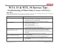
WTA 35 & WTL 54 Service Tips -Troubleshooting of Minor Faults (Customer Self-Help 1)
SELF-HELP
Dryers may exhibit problems that are unrelated to a malfunction of the dryer itself. The following table may serve to answer your
question about a problem you are having without having to call a serviceman.
PROBLEM
POSSIBLE CAUSE
‘‘On/Off’’ Indicator light does not come on.
• The ‘‘On/Off’’ button has not been depressed.
• A fuse may have blown or a circuit breaker tripped. Replace fuse or reset
circuit breaker at your fuse box/breaker box.
• The plug is not correctly or only loosely inserted into the receptacle.
Dryer does not start.
•
•
•
•
•
Cycle has not been selected.
“Start” button has not been depressed.
Door is not closed properly.
Room temperature is below 32 °F (0 °C)
If necessary, switch the machine off and wait 5 seconds before switching it
on again. Select the cycle again and depress “Start”.
Cycle is interrupted and ‘‘Lint Filter’’ light is
illuminated and buzzer sounds.
•
•
•
Clean Lint Filter as described in section titled CARE and CLEANING.
(WTA models) Check exhaust vent to see if it is blocked or too long.
(WTL models) Clean heat exchanger as described in section titled CARE and
CLEANING.
(WTL models) Check air inlet to make sure it is not blocked.
•
Cycle is interrupted, buzzer sounds, one or
several cycle indicators are flashing.
Indicates faulty operation:
• Clean the Lint Filter, check the exhaust duct length (WTA models),
• Switch the dryer off, wait for it to cool down and then restart.
Drying level not reached or drying time too
long.
•
•
702_58300000141665_ara_en_a
Clean the Moisture sensors in the drum as described in section titled CARE
and CLEANING.
If there is a power failure for an extended period the cycle must be restarted.
1st Edition/Revision 3 (4/11/03)
56
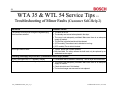
WTA 35 & WTL 54 Service Tips -Troubleshooting of Minor Faults (Customer Self-Help 2)
PROBLEM
POSSIBLE CAUSE
The laundry is not dry even though the highest drying
level has been selected.
• The drum is too full.
• The laundry was too wet when placed in the dryer.
• The room is not adequately ventilated. Make sure there is an adequate
supply of fresh air.
• The lint filter is blocked and should be cleaned.
• (WTA models) The exhaust vent is blocked or too long.
• (WTL models) The air inlet is blocked.
Drum light does not work
• “On/Off” button has not been pressed.
• Bulb has failed. For safety reasons the bulb must only be replaced by an
authorized service agent.
Following items apply only to the WTL (Condensation Electric Dryer) models
Cycle is interrupted and ‘‘E1’’ appears in display
• Condensate hose is blocked in some way. Turn off dryer and check hose.
Humidity level in room increases greatly
• The room is not adequately ventilated. Make sure there is an adequate
supply of fresh air.
• Check air inlet to see if it is blocked.
• The heat exchanger was removed but not replaced.
702_58300000141665_ara_en_a
1st Edition/Revision 3 (4/11/03)
57
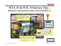
WTA 35 & WTL 54 Service Tips -Resistance Measurements from Control Module (1)
Disconnect & measure pink
2-pin connector to measure
heater E2 (800W). Heater
E2 should read 71 - 76 Ω.
WARNING!
Unplug dryer
before making
any resistance
measurements.
2
1
Disconnect & measure pin 2 (top)
of orange 2-pin connector & pin 1
(bottom) of pink 2-pin connector to
measure heater E3 (1900W).
Heater E3 should read 27 - 31 Ω.
Disconnect & measure 2-pin
connector (not shown) to measure
drain pump (WTL 54 models).
Pump should read ~ 110 - 136 Ω
702_58300000141665_ara_en_a
WTA 3510
model shown
1st Edition/Revision 3 (4/11/03)
58
WTA 35 & WTL 54 Service Tips -Resistance Measurements from Control Module (2)
Disconnect & measure white 2-pin
connector to measure NTC R2 (@
heaters). NTC R2 should read 18 - 22 kΩ.
1
Disconnect & measure white 3pin connector between pins 1-3
(pin 1 is at left) to measure NTC
R3 (@ door frame). NTC R3
should read 9 - 11 kΩ.
1
Disconnect & measure yellow 3-pin connector to measure
drum motor (with fan). Motor should read (pin 1 is at bottom):
• Pins 1-2:
19 - 25 Ω (WTL 54)
• Pins 1-2:
25 - 29 Ω (WTA 35)
• Pins 1-3:
18 - 23 Ω (WTL 54)
• Pins 1-3:
25 - 30 Ω (WTA 35)
WTA 3510
model shown
WARNING! Unplug dryer before making any resistance measurements.
702_58300000141665_ara_en_a
1st Edition/Revision 3 (4/11/03)
59
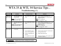
WTA 35 & WTL 54 Service Tips -Troubleshooting (1)
Fault code
Damp Dry
light flashes
Problem
NTC # R3 (@ bearing
shield) failed
Possible Cause
NTC (temperature sensor)
failed.
NOTE: When viewing wiring
diagram, see NTC # R3.
Regular Dry
light flashes
NTC # R2 (@ heaters)
failed
Solution
NOTE: NTC resistances:
NTC (temperature sensor)
failed.
NOTE: When viewing wiring
diagram, see NTC # R2.
Heater (dryer
overheated)
9 – 11 kΩ @ 59ºF – 221ºF
Check voltage at and wiring to NTC. Turn
off dryer, measure NTC resistance and
replace faulty NTC.
NOTE: NTC resistances:
Extra Dry
light flashes
Check voltage at and wiring to NTC. Turn
off dryer, measure NTC resistance and
replace faulty NTC.
18 – 22 kΩ @ 59ºF – 392ºF
Lint filter blocked.
Clean lint filter.
Vent is blocked or vent
hose is too long (WTA 35).
Clean vent and vent hose. If vent hose is
too long, shorten hose.
Dryer is overloaded with
laundry.
Empty clothes from dryer.
Fan impeller has loosened.
Tighten fan impeller. If fan impeller cannot
be tightened, replace it.
WARNING! Unplug dryer before starting any repairs.
702_58300000141665_ara_en_a
1st Edition/Revision 3 (4/11/03)
60
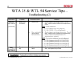
WTA 35 & WTL 54 Service Tips -Troubleshooting (2)
Fault code
Extra Dry
light flashes
Problem
Heater (dryer
overheated)
Possible Cause
Heater failed.
Solution
Check voltage at and wiring to heater. Turn off
dryer, measure heater resistance and replace faulty
heater.
NOTE: Heater resistances:
(continued)
Drum motor failed
(or drum drive
belt has broken).
62 – 67 Ω (800W - E2 on wiring diagram)
25 – 29 Ω (1900W – E3 on wiring diagram)
Check voltage at and wiring to drum motor. Turn off
dryer, measure motor resistance and replace faulty
motor. If drum drive belt has broken or is
excessively worn, replace it.
NOTE: Drum motor resistances (see wiring diagram):
AntiCrease/End
light flashes
Drying time too
long
Control module
failed.
19 – 25 Ω (between points X2.2-X2.3 for WTL 54)
18 – 23 Ω (between points X2.2-X2.4 for WTL 54)
25 – 29 Ω (between points X2.2-X2.3 for WTA 35)
25 – 30 Ω (between points X2.2-X2.4 for WTA 35)
Check voltage at and wiring to module. Turn off
dryer, and replace faulty module.
WARNING! Unplug dryer before starting any repairs.
702_58300000141665_ara_en_a
1st Edition/Revision 3 (4/11/03)
61
WTA 35 & WTL 54 Service Tips -Troubleshooting (3)
Fault code
Problem
Anti-Crease/End
light flashes
(continued)
Possible Cause
Solution
Moisture sensor(s)
failed.
Run moisture sensor conductance test. Check voltage
at and wiring to sensors. Turn off dryer and replace
faulty sensor(s).
Water level switch
failed (WTL 54 only).
Check voltage at and wiring to Hi-Limit. Turn off dryer,
measure Hi-Limit resistance and replace faulty Hi-Limit.
Hi-Limit ("overheat")
thermostat tripped
and failed to reset.
Reset Hi-Limit 1 . If still no heat, check voltage at and
wiring to Hi-Limit. Turn off dryer, measure Hi-Limit
resistance and replace faulty Hi-Limit.
Supply voltage too
low.
Have customer upgrade power system to provide
consistent voltage to dryer during heating (need min.
198V).
st
NOTE: Hi-Limit trips @ 248ºF (WTL 54) or 212ºF (WTA 35).
E1
Pump failed
(WTL 5400
condensation
dryer only)
Pump failed.
Check voltage at and wiring to pump. Turn off dryer,
measure pump resistance (110 – 136 Ω) and replace
faulty pump.
---
Dryer won't run
or indicator
lights won't
come on (no
power to dryer)
Dryer not turned on.
Turn "on/off" switch on.
No power to dryer.
Check customer circuit breaker, fuse box or power
connections.
Dryer fuse has
blown.
Unscrew holder cap & replace fuse (15A, type SC-15).
WARNING! Unplug dryer before starting any repairs.
702_58300000141665_ara_en_a
1st Edition/Revision 3 (4/11/03)
62
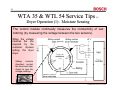
WTA 35 & WTL 54 Service Tips -Dryer Operation (1): Moisture Sensing
The control module continually measures the conductivity of wet
clothing (by measuring the voltage between the two sensors).
When the voltage
matches the one
required by the
customer dryness
setting, the dryer
stops.
(ground)
Sliding
contacts
(brushes) contact
the inner and outer
drums to give the
voltage readings.
702_58300000141665_ara_en_a
1st Edition/Revision 3 (4/11/03)
63
WTA 35 & WTL 54 Service Tips -Dryer Operation (2): NTC Locations
Two NTC sensors measure
the air temperature to
prevent overheating.
• NTC R2 -- Measures the
air temperature in front of
the heater.
• NTC R3 -- Measures the
air temperature at the dryer
door.
Top of heater housing
NTC R2
NTC R3 in bottom of door face frame
Hi-Limit
702_58300000141665_ara_en_a
HINT: Keeping lint filter &
vent hoses clean of lint will
keep NTC’s from tripping
unnecessarily.
1st Edition/Revision 3 (4/11/03)
64
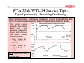
WTA 35 & WTL 54 Service Tips -Dryer Operation (3): Preventing Overheating
The control module continually measures drying temperatures and
turns off heaters as needed to lower temperatures to proper levels.
The control module
drops the heat setting
down
one
level
whenever overheating
occurs and whenever
the
drum
rotates
counterclockwise.
• From 3 (heater E2
+ E3) to 2 (heater
E3 only)
Temp.
Lowering temperature during drum ccw rotation
E2 + E3
E3 only
Off
Temp.
Correcting temperature overshoot
• From 2 (heater E3
only) to 0 (off - no
heat).
NOTE: Heaters cycle on and off as
needed to keep temperatures at
appropriate levels.
702_58300000141665_ara_en_a
1st Edition/Revision 3 (4/11/03)