1
PCL®-II Programmer’s Reference Manual
5525B/31/32 Line Matrix Printer
5525B/31/32 Line Matrix Printer
PCL®-II Programmer’s Reference Manual
P/N 422932-001
Compaq® makes no representations or warranties of any kind regarding this
material, including, but not limited to, implied warranties of merchantability
and fitness for a particular purpose. Compaq shall not be held responsible for
errors contained herein or any omissions from this material or for any
damages, whether direct, indirect, incidental or consequential, in connection
with the furnishing, distribution, performance or use of this material. The
information in this manual is subject to change without notice.
This document contains proprietary information protected by copyright. No
part of this document may be reproduced, copied, translated or incorporated
in any other material in any form or by any means, whether manual, graphic,
electronic, mechanical or otherwise, without the prior written consent of
Compaq.
COPYRIGHT 1999, COMPAQ COMPUTER CORPORATION
All rights reserved.
Trademark Acknowledgements
IBM and Proprinter are registered trademarks, and PC-DOS is a trademark of
International Business Machines Corporation.
Compaq is a registered trademark of Compaq Computer Corporation.
Epson is a registered trademark of Seiko Epson Corporation.
Hewlett-Packard, HP and PCL are registered trademarks of Hewlett-Packard
Company.
IGP, PGL, LinePrinter Plus, and Printronix are registered trademarks of
Printronix, Inc.
QMS is a registered trademark, and Code V is a trademark of Quality Micro
Systems, Inc.
This product uses Intellifont Scalable typefaces and Intellifont technology.
Intellifont is a registered trademark of Agfa Division, Miles Incorporated
(Agfa).
CG, Garth Graphic, Intellifont, and Type Director are registered trademarks,
and Shannon and CG Triumvirate are trademarks of Agfa Division, Miles
Incorporated (Agfa). CG Bodoni, CG Century Schoolbook, CG Goudy Old
Style, CG Melliza, Microstyle, CG Omega, and CG Palacio are products of
Agfa Corporation. CG Times, based on Times New Roman under license
from The Monotype Corporation Plc is a product of Agfa.
Univers is a registered trademark of Linotype AG and/or its subsidiaries.
Letraset is a registered trademark, and Aachen, Revue and University Roman
are trademarks of Esselte Pendaflex Corporation.
Futura is a registered trademark of Fundición Tipográfica Neufville, S.A.
ITC Avant Garde Gothic, ITC Benguiat, ITC Bookman, ITC Century, ITC
Cheltenham, ITC Clearface, ITC Galliard, ITC Korinna, ITC Lubalin Graph,
ITC Souvenir, ITC Tiepolo, ITC Zapf Chancery, and ITC Zapf Dingbats are
registered trademarks of International Typeface Corporation.
Albertus, Gill Sans, and Times New Roman are registered trademarks, and
Monotype Baskerville is a trademark of The Monotype Corporation Plc,
registered in the U.S. Pat. and TM office and elsewhere.
Hiroshige and Marigold are trademarks of AlphaOmega Typography, Inc.
Table of Contents
1 Introduction............................................................. 9
About This Guide ................................................................................. 9
Warnings and Special Information ................................................ 9
Related Product Information ......................................................... 9
Software Features ............................................................................... 10
2 HP PCL-II ............................................................. 11
Introduction .......................................................................................... 11
HP PCL-II Emulation Default Settings........................................... 12
Switching Between the Emulations ............................................... 12
Configuring the PCL-II Emulation with Control Codes......................... 13
Printer Feature Set Compatibility .................................................. 13
General Information ...................................................................... 14
Escape Sequences ....................................................................... 15
Programmable Reset .................................................................... 18
Character Font Selection .............................................................. 19
Printing in the Hex 80 through Hex FF Region.............................. 22
Print Pitch Selection ...................................................................... 22
Character Style Selection.............................................................. 22
Character Density Selection.......................................................... 23
Switching Character Fonts ............................................................ 25
Display Functions Mode ................................................................ 26
Self-test ......................................................................................... 26
Print Mode Selection ..................................................................... 26
Line Spacing ................................................................................. 27
Vertical Forms Control (VFC) ........................................................ 27
Standard (Computed) VFC............................................................ 27
Programmable VFC....................................................................... 29
Logical Page Length Selection...................................................... 37
Text Length (Vertical Margin) Selection ........................................ 38
Perforation Skip Mode................................................................... 38
Horizontal Margin Selection .......................................................... 39
Transparent Print Data .................................................................. 39
Cursor Control ............................................................................... 40
Raster Graphics ............................................................................ 41
Underlining .................................................................................... 42
Table of Contents
Character Overstrike ..................................................................... 43
Bar Codes ..................................................................................... 43
US Postnet Barcodes .................................................................... 52
4.0 CPI (20 Bars per inch) US POSTNET Bar Code .................... 55
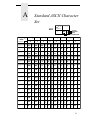
A Standard ASCII Character Set ............................. 57
1
Introduction
About This Guide
Your printer comes equipped with the standard Hewlett-Packard® Printer
Control Language (PCL®-II) emulation. This manual explains the emulation in
detail.
The Programmer’s Reference Manual is designed so that you can quickly find
the information you need to use and configure your Compaq® 5525B/31/32
Series printer.
Warnings and Special Information
Read and comply with all information highlighted under special headings:
WARNING
CAUTION
IMPORTANT
Conditions that could harm you as well as damage the equipment.
Conditions that could damage the printer or related equipment.
Information vital to proper operation of the printer.
NOTE: Information affecting printer operation.
Related Product Information
Refer to the following books for printer operation:
•
Compaq 5525B/31/32 Line Matrix Printer User’s Manual
Provides information about installing and using your printer, basic
operational procedures, configuration instructions, and troubleshooting
guidelines. Describes the keys on the control panel and provides quick
reference information on routine printer operations such as loading paper
and replacing ribbons.
•
Compaq 5525B/31/32 Line Matrix Printer LinePrinter Plus Programmer’s
Reference Manual
Covers the host control codes and programming information for the
LinePrinter Plus® emulations, including P-Series, IBM® Proprinter® XL
and Epson® FX.
•
Compaq 5525B/31/32 Line Matrix Printer Maintenance Manual
This manual is not shipped with the printer, but can be ordered. It explains
how to maintain and repair the 5525B/31/32 Series printer at the field
service level of maintenance. This manual covers alignments and
adjustments, preventive and corrective maintenance, troubleshooting,
and basic principles of operation.
9
Chapter
1
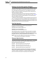
Software Features
Software Features
The PCL-II emulation software provides the following features:
10
•
Graphics and a selection of print densities. You can enable graphics
mode and specify a density mode (dots per inch).
•
Print Attributes. Characters can be bold, italic, double high, double wide,
etc.
•
Page Formatting. PCL-II commands allow you to set line spacing, page
length, and vertical forms control.
•
Font Typefaces. Also referred to as print modes. The five typefaces
include Near Letter Quality (NLQ), Data Processing (DP), High Speed
(HS), OCR A, and OCR B.
•
Character Sets. Forty-seven character sets are available. You can print
the character sets in the different print modes. (OCR A and B character
sets must be printed in OCR A and OCR B print modes.)
•
Bar codes. Several bar codes are available, including Code 3 of 9,
Industrial 2 of 5, Interleaved 2 of 5, UPC A, EAN 8, EAN 13, UCC/EAN128, UPCE, Royal Mail, Postnet 11.3 cpi, and Postnet 4 cpi.
2
HP PCL-II
Introduction
This chapter describes the HP® PCL-II emulation host control codes that are
supported for your 5525B/31/32 Series printer. Emulation refers to the ability
of a printer to execute the commands of a particular printer control language.
A printer control language is the coding system used to convey, manipulate,
and print data. It contains character codes and command sequences that
configure the emulation. In this manual, the terms emulation, printer protocol,
and printer control language are synonymous.
In the HP PCL-II emulation mode, your printer can print files coded for the HP
PCL-II printer control language. To select the PCL-II emulation mode as the
active printer emulation, select PCL-II in the ACTIVE EMULATION menu and
then the PCL-II menu will appear under the EMULATION menu, as described
in the Compaq 5525B/31/32 Line Matrix Printer User’s Manual .
The PCL-II emulation provides many configurable parameters. The default
parameter values for this emulation are shown in Table 1. You can modify the
emulation parameter values in two ways:
•
The PCL-II host control codes. An extensive set of PCL-II control code
commands can be sent to the printer from an attached host computer via
the host data stream. Most of this chapter is devoted to describing the
PCL-II control code commands.
•
The printer configuration menus. You can modify a subset of the PCL-II
emulation parameters using the printer configuration menus and control
panel keys as described in the Compaq 5525B/31/32 Line Matrix Printer
User’s Manual.
A parameter value set by a host control code overrides a value set from the
printer’s control panel.
NOTE: Configuration values selected from the menus or via host control
codes can be saved to memory so that they will not be lost when you
power off the printer. The menu selection for saving a configuration to
memory is described in the Compaq 5525B/31/32 Line Matrix Printer
User’s Manual.
11
Chapter
2
Introduction
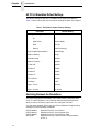
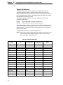
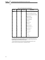
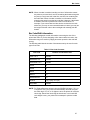
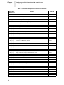
HP PCL-II Emulation Default Settings
The factory settings for the PCL-II emulation menu options are shown in
Table 1. Host control codes can override the settings for these menu options.
Table 1. PCL-II Menu Option Factory Settings
Parameter
Default Setting
Primary/Secondary Character Set
ID
0
Symbol Set
Roman-8(8U)
Pitch
10.0 cpi
Density
Data Processing
Page Length Representation
Inches/Page
Graphics Density
60 dpi
Perforation Skip
Disable
Display Functions
Disable
LF after CR
Disable
CR after LF
Enable
CR after FF
Enable
CR after VT
Enable
PTX Linefeed
Disable
LPI Adjust
6 LPI
Page L. /Lines
66 lines
Page L. /Inches
11 Inches
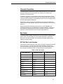
Switching Between the Emulations
The printer supports four emulations: PCL-II (the default), LinePrinter Plus,
Code V™ and IGP®/PGL®. The LinePrinter Plus has three protocols from
which to choose: P-Series, Proprinter III XL, and Epson FX-1050.
You can switch between PCL-II and any of the LinePrinter Plus protocols by
sending one of the following commands:
ESC%-00000X
ESC%-00001X
ESC%-00002X
SFCC|};K0
12
Switches from PCL-II to P-Series
Switches from PCL-II to Proprinter III XL
Switches from PCL-II to Epson FX-1050
Switches from any of the LinePrinter Plus emulations
to PCL-II
Printer Feature Set Compatibility
NOTE: The SFCC is the Special Function Control Code. From the P-Series
protocol, this code is selectable from the front panel. The default
value is hex 01. For the Proprinter and Epson emulations, the SFCC
is always the ESC (hex 1B) character.
Configuring the PCL-II Emulation with Control Codes
The remainder of this chapter describes the PCL-II printer control language
codes that may be sent from a host computer attached to the printer.
The escape (ESC) control code is used to select most of the programmable
features.
Commands and control codes sent from a host system override settings in the
configuration menus. However, any configuration settings from host control
codes will be gone once the printer is powered off (or reset to the default
values). Host control codes are never reflected in the PCL-II configuration
menu. In order to save a configuration, it is necessary to select the desired
options from the front panel and save the options to one of the printers eight
user-selectable configurations. The User’s Manual describes the menu option
for saving changes to the printer memory.
Printer Feature Set Compatibility
PCL-II standardizes printer features and user access of these features,
providing compatibility between HP printers. PCL-II is structured in five
feature levels:
•
•
•
•
•
Level I
Print and Space
Level II
EDP
Level III
Word Processing
Level IV
Page Formatting
Level V
Enhanced Page Formatting
Each PCL level supersedes features of the levels below it. The 5525B/31/32
printers are Level II printers, meaning that all applications for Level I and II
printers will operate correctly on your printer with no modifications.
In addition to supporting Level I and Level II features, the printer supports a
limited set of additional features that may not be supported by other HP
products. Applications written using these additional features may not operate
as intended on other Hewlett-Packard printers which do not have these
capabilities.
13
Chapter
2
Configuring the PCL-II Emulation with Control Codes
General Information
Programmatic Printer Control
Control codes and multi-character escape sequences are used to control the
printers.
The printers execute command parameters in the order they are received.
Therefore, the order of the parameters is significant. Unrecognized escape
sequences are ignored in their entirety and may cause erroneous printing
since the printer may be unable to perform the requested operation.
Logical and Physical Pages
The limits of the logical page determine the area in which printing can take
place. Logical page length is set programmatically (in lines per page).
Physical page length is set via the control panel and indicates the actual size
of a single page. The physical page length cannot be changed
programmatically. Refer to the User’s Manual for more information.
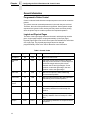
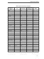
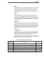
Table 2. Control Codes
Function
Symbol
Binary
Level
Backspace
BS
1000
II
Move one column left.
Horizontal
Tab
HT
1001
V
Move the current active position to the next
tab stop on the current line. The tab stops are
at the left margin and every 8th column
between the left and right margins. If new
position crosses the right margin, the new
position is set to the right margin.
Line Feed
LF
1010
I
Move to next print line while maintaining
current column position
Form Feed
FF
1100
I
Move to first line at top of the next page while
maintaining current column position
Carriage
Return
CR
1101
I
Move to the left margin on current print line
Shift Out
SO
1110
I
Select following characters from the current
secondary character font until receipt of a
Shift In
Shift In
SI
1111
I
Select following characters from the current
primary character font until receipt of a Shift
Out
Escape
ESC
11011
I
The following characters are a special control
sequence
14
Description
Escape Sequences
Escape Sequences
An escape sequence consists of the ESC control code followed by one or
more characters in succession. Both two-character and structured escape
sequences control the printer. Two-character escape sequences take the
form ESCX, where X is a character from the ASCII table (0 through ~).
Structured escape sequences take the following form:
ESCXy[parameter]Z
This sequence is explained below:
ESCXy
Prefix. This part of the escape sequence indicates that the
escape sequence is structured and also specifies which type of
control is being performed. “X” is referred to as the structured
character; “y” is referred to as the group character.
Parameter This string of ASCII characters specifies a value (either numeric
or alphanumeric).
Z
Terminator. This ASCII character indicates the function to which
the previous parameter value applies. If this character is lower
case (a,b,c, etc.), it indicates a combined escape sequence,
meaning that more structured information will follow. If the
character is upper case (A,B,C, etc.), it terminates the escape
sequence string.
NOTE: Brackets [ ] are shown in many of the escape sequences for
clarification purposes, but are not actually part of the escape
sequence. For example, the brackets in the escape sequence for
selecting page length (ESC&l[1-128]P) specify a range of values (1
through 128) for page length. To specify a page length of 35 lines, the
escape sequence ESC&l35P would be sent to the printer.
Combining Escape Sequences
Structured escape sequences can be combined to save keystrokes.
Combining sequences involves adding the parameter value and terminator of
one or more sequences to another escape sequence. Structured sequences
can be combined only if their prefixes are identical. When a parameter/
terminator of one sequence is added to another sequence, all of the
terminators except the last should be lower case. For example, to set the left
and right margins using two separate escape sequences, the following two
sequences would be sent:
Set left margin at position 10
ESC&a10L
Set right margin at position 99
ESC&a99M
Using one combined escape sequence, the following would be sent to the
printer:
ESC&a10l99M
15
Chapter
2
Configuring the PCL-II Emulation with Control Codes
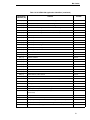
Table 3 lists the escape sequences you can use with the printer. Note that the
brackets [ ] used in these escape sequences are for clarification purposes
only (the brackets are not actually part of the commands).
Table 3. Line Printer Escape Sequences
Escape Sequence
Explanation
Page No.
PCL LEVEL I
ESCE
Software reset
18
ESCY
Display mode on
26
ESCZ
Display mode off
26
ESCz
Self test
26
ESC*rA
Raster graphics start
41
ESC*b[#]W[data]
Raster graphics data
41
ESC*rB
Raster graphics end
41
ESC&d[DEFGLMNOTUVW\}^]
Underline mode on
42
ESC&d[@CHIJKPQRSWXZ[]
Underline mode off
42
ESC&11L
Perf skip mode on
38
ESC&10L
Perf skip mode off
38
ESC&k[0,2]S
10 and 16.67 cpi
26
ESC[(,)] [#ID]
Primary/Secondary font symbol set
19
ESC[(,)]s[Cpi]H
Primary/Secondary font cpi
22
ESC&1[6,8]D
6/8 lpi
26
ESC&1[1-128]P
Page length in lines
37
ESC&1[1-128]F
Text length in lines
38
ESC&a[print position]L
Left margin set
39
ESC&a[print position]M
Right margin set
39
ESC&p[#]X
Transparent mode
39
ESC&a[#]R
Move to absolute row position
40
ESC&a[#]C
Move to absolute column position
40
ESC&a[+#]R
Move to relative row position
40
ESC&a[+/-#]C
Move to relative column position
40
PCL LEVEL II
16
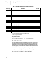
Escape Sequences
Table 3. Line Printer Escape Sequences (continued)
Escape Sequence
Explanation
Page No.
PCL LEVEL III
ESC[(,)]s[0,1]S
Italics for primary/secondary font
22
ESC[(,)]s[0,1,-1]Q
Density for primary/secondary font
22
ESC&k4S
12 cpi selection
26
ESC*t[70,140]R
Raster graphics vertical and horizontal dpi
selection
41
ESC*r[60,70,120,140]L
Raster graphics horizontal dpi selection
41
ESC*r[72,144]V
Raster graphics vertical dpi selection
41
ESC&10V
Move to TOF of physical page, VFC channel 0.
27
ESC&1[1-16]
Select VFC channel
29
ESC&1[#bytes]W[data]
Program VFC
29
ESC*z[#]H
Bar code height
43
ESC*z[#]Q
Bar code PDF position
43
ESC*z[#]V
Bar code type selection
43
ESC*z[<bar data>]Z
Bar code data
43
ESC*b[#]Y
Move # raster lines
41
ESC&k8S
Double size print mode on
26
17
Chapter
2
Configuring the PCL-II Emulation with Control Codes
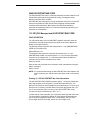
Programmable Reset
The programmable reset escape sequence (ESCE) causes the printer to eject
paper to the top-of-form (position 0,0) if not already at top-of-form. This
command resets all current printer configuration values to the following
states. The printer remains on-line after a programmable reset. When the
printer is reset, it is set to a known state as follows:
18
•
Primary and secondary character sets (fonts) as configured from the
control panel.
•
•
Vertical line spacing (6/8 LPI) as configured from the control panel.
•
•
Data buffer is printed and then the buffer is cleared.
•
•
•
•
•
Margins set at maximum limits and/or Left margin set at first column (0).
•
•
•
•
•
Display functions off and Underline enhance disabled.
Paper moves to the next Top of Form position (if not currently at Top of
Form).
Standard VFC channel assignments selected as defined by physical page
length.
Physical page length remains as configured from the control panel.
Logical page length = physical page length
Text length = logical page length minus one inch
All character font attributes (symbol set, pitch, style, and density) default
to the character font configured from the control panel.
Perforation skip mode as configured from the control panel.
Enable/Disable Label Card as configured from control panel.
Printronix linefeed emulation as configured from control panel.
Raster graphics horizontal resolution as configured from the control
panel. Vertical resolution set to 72 dots per inch.
Character Font Selection
Character Font Selection
The printer can print several different character sets (fonts). By performing a
printer self-test, you can see which fonts are installed in your printer. You may
specify any of these fonts from an application. On the self-test printout, each
available character font is printed along with a parameter number to the left of
the printed font.
There are two ways to select a font from those available:
•
By entering the parameter number via the control panel (function 1 =
primary character set; function 2 = secondary character set)
•
By specifying the attributes of the desired fonts using escape sequences.
The list below contains the font attributes, listed in order of descending
priority:
•
•
•
•
Symbol Set (ASCII, Roman-8, Line Draw, etc.)
Pitch (10,12,13.3,15,16.67, 20)
Style (Upright/Italic)
Density (High-Speed, Near Letter Quality)
The attributes are specified for both primary and secondary fonts so that you
may switch between the primary and secondary fonts using the Shift Out (SO)
and Shift In (SI) control codes. Notice that the only difference between the
primary and secondary font escape sequences is the direction of the
parentheses. The left parenthesis “(“ is used for primary fonts and the right
parenthesis “)” for secondary. Upon receiving these font attribute commands,
the printer selects the best fitting font from those available.
It is not necessary to specify all four font attributes when selecting a font. If
any of the attributes are not specified, the printer defaults to those attributes
last specified (or, if none have been specified, from the control panel default
font). For example, if you wish to select a font without selecting a print pitch,
the print pitch last specified will be in effect. If you had not previously specified
a print pitch, the printer will use the print pitch of the default font that was last
specified from the control panel (provided that the particular symbol set
selected is available in the current pitch).
The escape sequences used for specifying the character font attributes are
explained in the following paragraphs.
19
Chapter
2
Configuring the PCL-II Emulation with Control Codes
Symbol Set Selection
The printer allows you to select a symbol set. A symbol set is a set of
characters that are mapped to certain locations in the printer’s memory.
Symbol sets differ from one another in the characters contained in the set and
in their locations within memory. The default symbol set is that of the default
font specified from the control panel.
The following escape sequences are used to specify the primary and
secondary symbol sets:
ESC(ID
Select symbol set for primary character font
ESC)ID
Select symbol set for secondary character font
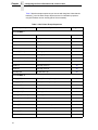
Table 4 lists the ID’s needed to select each symbol set. For example, to select
the Roman-8 symbol set for the primary font, you would send the ESC(8U
escape sequence. To select OCR-B for the secondary font, you would send
ESC)1O to the printer.
An ASCII symbol set table is provided in Appendix A.
NOTE: Any number of fonts may be printed on each line, but to do this, each
font must be the same pitch and typeface. That is, only one print
pitch, or typeface is allowed per line.
Table 4. Symbol Set Selection
Symbol Set
Name
ID
Classification
Printable in hex
80-9F Range
Mode
Roman-8*
8U
8-Bit
No
1
Turkish-8
8T
8-Bit
No
1
Arab-8
8V
8-Bit
No
1
Cyrillic-8
8R
8-Bit
No
1
ASCII
0U
7-Bit
No
0
Math Symbol
0A or 0M
7-Bit
No
0
Line Draw Set
0B or 0L
7-Bit
No
0
ISO Den/Nor
0D
7-Bit
No
0
Roman Ext Char
0E
7-Bit
No
0
ISO UK
1E
7-Bit
No
0
ISO France
0F
7-Bit
No
0
ISO German
0G
7-Bit
No
0
Hebrew
0H
8-Bit
No
1
Japan ASCII
0K
7-Bit
No
0
Katakana
1K
8-Bit
No
1
Block Char
1L
7-Bit
No
0
20
Character Font Selection
Table 4. Symbol Set Selection (continued)
Symbol Set
Name
ID
Classification
Printable in hex
80-9F Range
Mode
OCR-A
0O
7-Bit
No
0
OCR-B
1O
7-Bit
No
0
ISO Swe/Fin
0S
7-Bit
No
0
ISO Spain
1S
7-Bit
No
0
ISO Italian
0I
7-Bit
No
0
ISO Portugu
4S
7-Bit
No
0
Latin-1
0N
8-Bit
No
1
Latin-2
2N
8-Bit
No
1
Latin-5
5N
8-Bit
No
1
Latin-6
6N
8-Bit
No
1
Baltic
19L
8-Bit
No
1
PC-8 DanNor
11U
8-Bit
Yes
2
PC-8 Code 437
10U
8-Bit
Yes
2
PC-850 MtLi
12U
8-Bit
Yes
2
PC-851 Lt/Gk
12G
8-Bit
Yes
2
PC-852 Lat2
17U
8-Bit
Yes
2
PC Turkish
9T
8-Bit
Yes
2
PC Hebrew
15H
8-Bit
Yes
2
PC Lat/Ara
10V
8-Bit
Yes
2
PC Cyrillic
3R
8-Bit
Yes
2
Win 3.1 Latin-1
19U
8-Bit
Yes
2
Win 3.1 Latin-2
9E
8-Bit
Yes
2
Win 3.1 Latin-5
5T
8-Bit
Yes
2
Math-8
8M
8-Bit
No
1
PS Math
5M
8-Bit
No
1
Greek-7
12N
8-Bit
No
1
Postnet 4
15Y / 0K
7-Bit
No
1
Postnet 11.25
1K
7-Bit
No
1
Greek-8
8G
8-Bit
No
1
Hebrew-8
8H
8-Bit
No
1
Katakana-8
8K
8-Bit
No
1
21
Chapter
2
Configuring the PCL-II Emulation with Control Codes
Printing in the Hex 80 through Hex FF Region
The printer exhibits different behaviors as it processes characters in the hex
80 through FF range. Behavior is based upon the symbol set of the active
font. If the symbol set of the active font is 7-bit, characters in the hex 80
through FF range will be ignored. If the symbol set is 8-bit, the printer will
attempt to process the characters.
There are two different types of 8-bit sets. Some have characters that are
printable in the hex 80 through 9F region, while others do not. (See Table 4).
If the active symbol set does not have printables in the hex 80 through 9F
range, the characters are ignored.
To determine symbol set properties, perform a symbol set print from the PCL
menu. 7-bit sets print only one line of characters, while 8-bit sets print two. 8bit sets, with printables in the hex 80 through 9F range, print characters in the
space below the control code on the first line. Those without printables in that
range leave the area under the control codes blank.
Print Pitch Selection
Print pitch is specified using the following escape sequences:
ESC(s[5,10,12,13.3,15,16.7,20.0]H
Select print pitch for primary character font
ESC)s[5,10,12,13.3,15,16.7,20.0]H
Select print pitch for secondary character font
When specifying a pitch, if no font with the exact size specified is available,
the next larger pitch will be designated. If a larger pitch does not exist, the
pitch will be set to 16.67. Only one pitch per line may be selected. The default
print pitch is that of the primary font specified from the control panel.
NOTE: Refer to the User’s Manual to see which pitches are available for
different symbol set and typeface combinations.
Character Style Selection
The printer has two types of character styles: upright and italic. The following
escape sequences select either the upright or the italic print style for the
primary and secondary character fonts:
ESC(s0S
Selects the upright style for the primary font
ESC(s1S
Selects the italic style for the primary font
ESC)s0S
Selects the upright style for the secondary font
ESC)s1S
Selects the italic style for the secondary font
Italics cannot be selected or saved from the control panel. The printer will
default to the upright style when the printer is first powered on. Changing
emulations, loading a configuration, or sending the ESCE command to the
printer will cancel the italic style for the primary and secondary fonts.
22
Character Density Selection
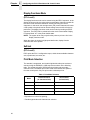
Character Density Selection
(PCL Level III)
Standard-density print, high-density print, and high-speed draft printing can
be specified using the following escape sequences:
Primary Selection
ESC(s0Q
Select Standard-Density (12 x 9 dot matrix, 120 x 72 dpi) for the
primary font
ESC(s1Q
Select High-Density (18 x 12 dot matrix, 180 x 96 dpi) for the
primary font
ESC(s-1Q Select High-speed Draft Printing (12 x 6 dot matrix, 120 x 48 dpi)
for the primary font
Secondary Selection
ESC)s0Q
Select Standard-Density (12 x 9 dot matrix, 120 x 72 dpi) for the
secondary font
ESC)s1Q
Select High-Density (18 x 12 dot matrix, 180 x 96 dpi) for the
secondary font
ESC)s-1Q Select High-speed Draft Printing (12 x 6 dot matrix, 120 x 48 dpi)
for the secondary font
The default density is that of the default font specified from the control panel.
If the symbol set selected is not available in the requested density, the printer
will print blank space. However, OCR-A, OCR-B, and Postal Barcodes force
density changes to ensure scanability.
When draft printing is selected, the printer prints less dots vertically (5 dots).
This reduction in dots results in an increase in print speed of up to 30%.
For example, to cue high-density ASCII:
ESC(0UESC(s1Q
To cue high-speed draft with Roman Extension:
ESC(0EESC(s-1Q
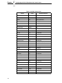
The following table lists all the Symbol Sets available to the PCL II Emulation.
Each Symbol Set is followed by its selection Code, and the Densities(Pitches)
that it is available in. With the exception of OCR-A and OCR-B, selecting a
symbol set in a Density combination not listed in the chart below will result in
spaces being printed in place of the desired character.
23
Chapter
2
Configuring the PCL-II Emulation with Control Codes
Table 5. Available Symbol Sets
Name
24
Code
Density (Pitches)
Roman-8
8U
HS DP NLQ
Turkish-8
8T
HS DP NLQ
Arab-8
8V
HS(5,10) DP NLQ
Cyrillic
8R
HS(5,10) DP NLQ
ASCII
0U
HS DP NLQ
Math Symb
0A/0M
HS DP NLQ
Line Draw Set
0B/0L
DP
ISO Den/Nor
0D
HS DP NLQ
Roman Ext
0E
HS DP NLQ
ISO UK
1E
HS DP NLQ
ISO France
0F
HS DP NLQ
ISO German
0G
HS DP NLQ
Hebrew
0H
HS DP NLQ
Japanese ASCII
0K
HS DP NLQ
Katakana
1K
DP(5,10) NLQ(5,10)
Block Char
1L
DP
OCR-A
0O
OCRA(10)
OCR-B
1O
OCRB(10)
ISO Swe/Fin
0S
HS DP NLQ
ISO Spain
1S
HS DP NLQ
ISO Italian
0I
HS DP NLQ
ISO Portugu
4S
HS DP NLQ
Latin-1
0N
HS DP NLQ
Latin-2
2N
HS DP NLQ
Latin-5
5N
HS DP NLQ
Latin-6
6N
HS DP NLQ
Baltic
19L
HS DP NLQ
PC-8 DanNor
11U
HS DP NLQ
PC-8 Cd 437
10U
HS DP NLQ
PC-850 MtLi
12U
HS DP NLQ
PC-851 LtGk
12G
HS DP NLQ
Switching Character Fonts
Table 5. Available Symbol Sets (continued)
Name
Code
Density (Pitches)
PC-852 Latin2
17U
HS DP NLQ
PC Turkish
9T
HS DP NLQ
PC Hebrew
15H
HS DP NLQ
PC Lat/Ara
10V
HS(5,10) DP NLQ
PC Cyrillic
3R
HS DP NLQ
Win3.1 Lat1
19U
HS DP NLQ
Win3.1 Lat-2
9E
HS DP NLQ
Win3.1 Lat-5
5T
HS DP NLQ
Math-8
8M
DP NLQ
PS Math
5M
DP NLQ
Greek 7
12N
HS DP NLQ
Postnet 4
15Y
NLQ(4)
Postnet 11.3
1K
NLQ(11.25)
Greek-8
8G
HS DP NLQ
Hebrew-8
8H
HS DP NLQ
Katakana-8
8K
DP(5,10) NLQ(5,10)
NOTE: All fonts support the following pitches unless otherwise noted: (5, 10,
12, 13.3, 15, 16.67, 20).
Switching Character Fonts
Character fonts can be accessed using the Shift In/Shift Out (SI/SO) control
codes.
The SO (CTRL N) control code is sent to the printer to access the secondary
font; the SI (CTRL O) control code is sent to select the primary font.
25
Chapter
2
Configuring the PCL-II Emulation with Control Codes
Display Functions Mode
(PCL Level I)
The display functions mode can be entered using the ESCY sequence. In the
display functions mode, the printer prints representative character symbols for
the control code characters instead of actually executing the control
characters. In this mode, the carriage return (CR) control character will cause
a CR symbol to be printed and an actual carriage return and line feed to be
performed. The display functions mode can be exited by sending an ESCZ
sequence. The ESCZ will be printed before the mode is terminated. Display
Functions Mode “off” is the printer default state.
NOTE: The system driver may only allow the printer to print one line in the
display functions mode.
When the printer is printing in high-speed draft mode, display function
characters will not be printed.
Self-test
(PCL Level I)
ESCz prints the PCL-II configuration report, which shows available character
sets, symbol sets, bar codes, etc.
Print Mode Selection
The standard, compressed, and double-high/double-wide print modes are
selected using the ESC&1[0,2,4,8]S sequence as shown in the following
table. This escape sequence affects both the primary and secondary
character fonts. The default print mode is that of the default font specified
from the control panel. Only one print mode is allowed per line.
Table 6. Print Mode Selection
Horizontal Pitch
(in characters/inch)
Mode
Vertical Pitch
(in lines/inch)*
0
10.0
6 or 8
2
16.67
6 or 8
4
12.0
6 or 8
8**
5.0
3 or 4
* Dependent on current line spacing.
** Double high/double wide character set selection.
26
Line Spacing
Line Spacing
Vertical line spacing of 6 or 8 LPI (lines per inch) can be selected either from
the control panel or remotely using the ESC&l[6 or 8]D sequence. When the
printer is reset, the vertical line spacing is as set from the control panel. If a
parameter other than 6 or 8 is entered, the command is ignored and no line
spacing change is made.
NOTE: Changing the line spacing causes the standard VFC table to be
recalculated.
Vertical Forms Control (VFC)
Vertical forms control (VFC) is a feature which allows increased throughput by
enabling the printer to skip to predetermined print locations. Key page
locations, such as top of form, half form, double space, and triple space, are
referred to as channels (0 through 16) and are stored in a VFC “table.”
The printer has both a standard (computed) VFC and a programmable VFC.
The following paragraphs explain each in more detail.
NOTE: In most situations, the printer's standard (computed) VFC page length
setting, as determined from the front panel, meets the application
requirements. Refer to the User’s Manual for information on setting
the page length from the front panel.
Standard (Computed) VFC
The printer VFC uses the logical page and form length (text length) to
calculate the distance to be skipped for each VFC channel. This information is
then loaded into the printer's VFC “table.” The “table” is 16 channels wide and
n lines long, where n is the logical page length in number of lines. A VFC
channel contains a 1 in this table on every line it can access. If the VFC
channel cannot access the line, a 0 is placed on that line for that channel. For
example, to specify a skip to the next half form, a program would specify VFC
channel 6. Notice in the sample on page 35 that 1's are placed in the table at
the half form position (lines 1 and 9). Then, for example, if the printer has
finished printing line 2 and channel 6 is selected, the paper will be advanced
to line 9.
To use the standard VFC, perform the ESC&l[0 through 16]V sequence using
the appropriate parameter number listed in Table 7.
27
Chapter
2
Configuring the PCL-II Emulation with Control Codes
Table 7. VFC Default Channel Definitions
Prefix
ESC&l
Parameter
Terminator
0
v/V
Explanation
*Conditional Top of Physical Page
1
Top of Form (first line of text)
2
Bottom of Form (last line of text)
3
Single spacing
4
**Double spacing
5
**Triple spacing
6
Half form
7
Quarter form
8
Tenth line
9
Bottom of Form
10
Bottom of Form - 1
11
Top of Form - 1
12
Top of Form
13
Seventh line
14
Sixth line
15
Fifth line
16
Fourth line
*All escape sequences except ESC&l0V refer to the logical page rather than
the physical page. This escape sequence causes a skip to the top of the next
physical page (unless already at top of page).
**These channels cause a move to the next double/triple space line, and
therefore may not actually perform a double/triple space.
28
Programmable VFC
Programmable VFC
Programmable VFC allows the user to specify paper movement information
other than the standard VFC definitions shown in Table 7. VFC information is
stored in the memory (RAM) table just as the standard VFC is, only the bytes
of information are loaded into RAM using the following escape sequence:
ESC&l[byte count]W[VFC data]
The byte count parameter specifies the number (in decimal 0 - 255) of VFC
data bytes to expect immediately following the termination of the escape
sequence.
NOTE: An even byte count must be indicated. If an odd byte count is
indicated, the VFC table in RAM will not be overwritten and the data
bytes following the ESC sequence will be read and discarded.
VFC data is the binary data which is loaded into the VFC table in RAM. These
8-bit bytes are sent in the following order following the ESC sequence
terminator: the most significant byte of the first word followed by the least
significant byte of the first word, followed by the most significant byte of the
second word, etc. The most significant bit of each word is channel 16 and the
least significant bit of each word is channel 1.
VFC Data = (MS byte) (LS byte) (MS byte) (LS byte) . . .
(word 1 = line 1) (word 2 = line 2) . . .
Once the VFC has been loaded into the RAM table, the VFC channels are
selected using the ESC&l[0 through 16]V sequence in the same manner as
the standard VFC. The standard and programmable VFC both use the same
table in RAM. Resetting the printer causes the standard VFC to be
recalculated using the current page and text (form) length and a new table to
be overwritten in RAM. The VFC table is also recalculated when the line
spacing, text length, or page length changes.
NOTE: If the I/O is configured for 7 bit data, channels 8 and 16 cannot be
downloaded with confidence since the eighth bit is used for the
communication protocol. Selecting channels 8 or 16 for 7 bit data is
not recommended.
Special VFC Considerations
Before loading a VFC table, it is recommended that a VFC select of channel 0
be performed. This will bring the printer to the top of the physical page.
When a programmed VFC is loaded into RAM, the logical page length is
automatically calculated using the following formula:
Logical Page Length (in number of lines) = byte count /2
The example on page 35 shows a VFC table which uses “standard” VFC
definitions and also illustrates a programmable VFC.
Example: Defining a 3.5 inch form at six lines per inch.
1 inch = 6 lines x 3.5 inches = 21 lines
29
Chapter
2
Configuring the PCL-II Emulation with Control Codes
Programmable VFC Using PCL
Programmable VFC’s using PCL seem to cause a lot of problems and
misunderstandings. Most of the misunderstanding concerns the use of the
escape sequence used to set the VFC file. This escape sequence is used to
override the default VFC of the printer. This escape sequence can be hardcoded into a program or ASCII file.
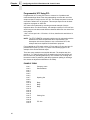
VFC’s are best understood by reviewing an actual example of how to
implement them. For this discussion, the example consists of a 3.5 inch form
at six lines per inch with several different channels defined for use on the form
to be printed.
1 inch = 6 lines per inch x 3.5 inches = 21 lines; therefore this would be a 21
line form.
NOTE: The TEXT LENGTH command could be used in conjunction with the
standard VFC and accomplish the above requirements. The
assumption is there are reasons to use a customized VFC; this
example has been simplified for clarification purposes.
First, establish the VFC length: with a 3.5” form and 6 LPI print, we have 21
potential lines of print (3.5 x 6 = 21). Refer to the following figure for an
example of the desired finished output.
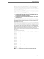
There are many methods to accomplish this task. The simplest way is to
provide a “1” in CH3 (Channel 3) for all possible print lines and simply call
CH3 for each line (including blank lines). This is called “line counting” and
leaves the burden of positioning with the programmer (adding or deleting a
line causes an adjustment elsewhere to be made).
EXAMPLE FORM
Line 1
Line 2
Line 3
Line 4
Line 5
Line 6
Line 7
Line 8
Line 9
Line 10
Line 11
Line 12
Line 13
Line 14
Line 15
Line 16
Line 17
Line 18
Line 19
Line 20
Line 21
30
Company name
Street address
Opening line
Body
Body
Body
Closing line
P.S. line
Programmable VFC
A second method involves only providing a “1” in CH3 where print will occur.
The programmer then simply calls CH3 and the blank lines are skipped.
There still is no flexibility for adding or deleting lines without VFC modification,
but line counting is minimized.
A third method involves assigning VFC channels to each section of the letter
and performing a call to CH3 within each section. To do this, the manufacturer
highly recommends following these guidelines:
•
•
CH1 should always define TOF and must be present for a valid load.
•
CH3 should be present for any potential print line except in the vertical
margin area (if any).
CH2 should always define BOF allowing for vertical margin (if any) and
must be present for valid paper out conditions.
For this example, CH1 will occur at line 1 and is aligned with the Company
Name. We will arbitrarily assign CH4 to occur at line 7 (Opening Line), CH5 to
occur at line 10 (Body), CH6 to occur on line 17 (Closing Line) and CH7 to
occur on line 20 (P.S. Line).
With the above channel assignments in mind, the programmer would call CH1
to begin the letter. After printing the name and address (using calls to CH3 to
“move” to each line) the programmer would call CH4 to skip to line 7 and print
the opening line. Next, a call is made to CH5 to skip to line 10 and print the
body, CH6 to print the closing and CH7 to print the P.S. line. This gives each
section flexibility by allowing variable sizes, limited by the physical room
available before interfering with the next section and avoiding the drudgery of
line count.
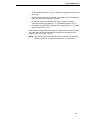
The above VFC would look like:
Channel
Line 1
Line 2
Line 3
Line 4
Line 5
Line 6
Line 7
Line 8
Line 9
Line 10
Line 11
Line 12
Line 13
Line 14
Line 15
Line 16
Line 17
Line 18
Line 19
Line 20
Line 21
1
1
2
1
3
1
1
1
1
1
1
1
1
1
1
1
1
1
1
1
1
1
1
1
1
1
4
5
6
7
8
9
10 11 12 13 14 15 16
1
1
1
1
NOTE: A “1” corresponds to a hole punched in a physical paper tape.
31
Chapter
2
Configuring the PCL-II Emulation with Control Codes
Notice that for each line channel 3 is selected, this would select a single
space advance. A 1 could be placed in any or all other channels and the VFC
would still be valid since the printer will only look at the channel selected and
advance to the next line that contained a 1 in that channel. For example, if the
printer was on line 2 and channel 7 was selected, the printer would advance
or slew down to line 20 which is the first line where there is a “1” in channel 7.
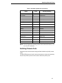
The next step would be to convert the above VFC definition into the escape
sequence format. The VFC data portion of the escape sequence reverses the
order of the channels. Once reversed, the 16 bits are then divided into two, 8bit bytes, with channel 16 being the Most Significant Bit (MSB) of the word
and channel 1 the Least Significant Bit (LSB) of the word. Refer to Table 8.
Since the escape sequence requires the VFC data to be in ASCII format this
binary data must be converted to ASCII. As in our example, many characters
may convert to “unprintable” ASCII characters (below ASCII OCTAL 037).
Refer to the ASCII Symbol Set chart in Appendix A. Entering unprintable data
can be done in several ways:
The easiest and preferred method involves using “dummy” VFC channels to
cause the converted character to become a printable one. For example,
always have bit 7 and bit 15 a “1”, thus adding %100 to the unprintable
character, and eliminating the confusion of entering unprintable data. Do not
“call” the corresponding channel bit 7 or 15 or else improper spacing will
occur.
If the VFC channels that bits 7 and 15 represent must be used, these
unprintable characters must be manipulated for data entry. In most cases, this
can be dealt with by using the DISPLAY FUNCTIONS mode of your terminal.
Type in the “ESC&l[byte count]W” followed by the ASCII characters using the
CONTROL key with the corresponding letter. (Since the CONTROL key
subtracts %100 (100 OCTAL) simply add %100 to the “unprintable” character.
For example, 00000101 converts to %5, adding %100 gives you a %105
which is an E, therefore, pressing a CONTROL E gives the desired result.)
If your terminal doesn't have a DISPLAY FUNCTIONS mode, some EDITOR
programs allow entering the OCTAL equivalents. Some editors do not allow
the user to directly enter OCTAL numbers. In this case, a “dummy” character
would be entered as the VFC data. Next, the EDITOR “CHANGE” command
would be used to change the dummy character to the desired ASCII
character. For example, place an “x” as a dummy character in the VFC data
and use the CHANGE command to replace the “x” with an ASCII 01 (SOH
character) by typing “CHANGEQ “x” to ‘01”. This would replace the “x” with
the unprintable ASCII 01; your escape sequence would appear one character
shorter without DISPLAY FUNCTIONS mode turned on.
This could also be accomplished by changing the specific column to the
ASCII character required. It is important to specify the starting and stopping
column or the CHANGE command will act as a column INSERT. For
example, if column 10 on line 2 is to be changed to an ASCII 04 you would
type “CHANGEQ 10/10 TO '04 IN 2”.
NOTE: The “ ' ” is the single quote and not the prime character.
There are several methods to enter data in the Workstation Configurator:
•
32
Entering data as a decimal number, i.e. 13 for a carriage return.
Programmable VFC
•
As an OCTAL number (one byte at a time) by preceding the number with
the % sign.
•
As a two or three character mnemonic such as BS or DC1 (see Appendix
B of the Workstation Configuration manual).
•
By entering the control characters with the up-arrow or circumflex
character preceding the character, i.e. a backspace would be an ^H.
•
By entering the actual ASCII character within single quotes, i.e. ’A’ would
equate to an OCTAL %101.
Each character entered, with the exception of multiple ASCII characters within
the single quote, MUST BE separated by commas. An example would be
“ESC, '&16W', %101, 'ABC', BS, 13”.
NOTE: Only one byte may be specified at a time in OCTAL, thus allowing a
maximum of OCTAL 377 which would place a 1 in columns 1-8.
33
Chapter
2
Configuring the PCL-II Emulation with Control Codes
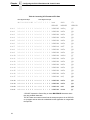
Table 8. Converting VFC Format to VFC Data
Most Significant Byte
Least Significant Byte
16 15 14 13 12 11 10 9 8 7 6 5 4 3 2 1 Octal
MSB/LSB
ASCII
CTL
MSB/LSB
MSB/LSB
Line 1
0 0 0 0 0 0 0 0 0 0 0 0 0 1 0 1 %000%005
NulEnq
@E
Line 2
0 0 0 0 0 0 0 0 0 0 0 0 0 1 0 0 %000%004
NulEot
@D
Line 3
0 0 0 0 0 0 0 0 0 0 0 0 0 1 0 0 %000%004
NulEot
@D
Line 4
0 0 0 0 0 0 0 0 0 0 0 0 0 1 0 0 %000%004
NulEot
@D
Line 5
0 0 0 0 0 0 0 0 0 0 0 0 0 1 0 0 %000%004
NulEot
@D
Line 6
0 0 0 0 0 0 0 0 0 0 0 0 0 1 0 0 %000%004
NulEot
@D
Line 7
0 0 0 0 0 0 0 0 0 0 0 0 1 1 0 0 %000%014
NulFF
@L
Line 8
0 0 0 0 0 0 0 0 0 0 0 0 0 1 0 0 %000%004
NulEot
@D
Line 9
0 0 0 0 0 0 0 0 0 0 0 0 0 1 0 0 %000%004
NulEot
@D
Line 10
0 0 0 0 0 0 0 0 0 0 0 1 0 1 0 0 %000%024
NulDc4
@T
Line 11
0 0 0 0 0 0 0 0 0 0 0 0 0 1 0 0 %000%004
NulEot
@D
Line 12
0 0 0 0 0 0 0 0 0 0 0 0 0 1 0 0 %000%004
NulEot
@D
Line 13
0 0 0 0 0 0 0 0 0 0 0 0 0 1 0 0 %000%004
NulEot
@D
Line 14
0 0 0 0 0 0 0 0 0 0 0 0 0 1 0 0 %000%004
NulEot
@D
Line 15
0 0 0 0 0 0 0 0 0 0 0 0 0 1 0 0 %000%004
NulEot
@D
Line 16
0 0 0 0 0 0 0 0 0 0 0 0 0 1 0 0 %000%004
NulEot
@D
Line 17
0 0 0 0 0 0 0 0 0 0 1 0 0 1 0 0 %000%044
Nul$
@$*
Line 18
0 0 0 0 0 0 0 0 0 0 0 0 0 1 0 0 %000%004
NulEot
@D
Line 19
0 0 0 0 0 0 0 0 0 0 0 0 0 1 0 0 %000%004
NulEot
@D
Line 20
0 0 0 0 0 0 0 0 0 1 0 0 0 1 0 0 %000%104
NulD
@D*
Line 21
0 0 0 0 0 0 0 0 0 0 0 0 0 1 1 0 %000%006
NulAck
@F
* DO NOT depress the Control Key on these BOLDFACE characters since
they are printable characters.
This VFC data can now be entered into the escape sequence in an ASCII file
or a program and can either be embedded into the application or merged with
the spool file.
34
Programmable VFC
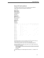
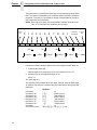
Example VFC Data Entry Methods
The example escape sequence may be created while the DISPLAY
FUNCTIONS key has been enabled as shown below.*
Top of Form
Bottom of Form
Single Spacing
Double Spacing**
Triple Spacing**
Half Form
Quarter Form
Tenth Line
Bottom of Form
Bottom of Form - 1
Top of Form - 1
Top of Form
Seventh Line
Sixth Line
Fifth Line
Fourth Line
Channels
Line 1
Line 2
Line 3
Line 4
Line 5
Line 6
Line 7
Line 8
Line 9
Line 10
Line 11
Line 12
Line 13
Line 14
Line 15
Line 16
Line 17
Line 18
Line 19
Line 20
Line 21
1
1
2
1
3
1
1
1
1
1
1
1
1
1
1
1
1
1
1
1
4
1
5
1
6
1
7
1
8
1
9
10 11 12 13 14 15 16
1 1 1 1 1
1
1
1
1
1
1
1
1
1
1
1
1
1
1
1
1
1
1
1
1
1
1
1
1
1
1
1
1
*This sample shows a 21-line VFC table at 6 LPI. The text ends at line 14,
leaving 6 blank lines (one inch) at the bottom of the page.
**These channels cause a move to the next double/triple space line.
Press the CONTROL key before each letter of the VFC data except for the
two BOLDFACE characters.
ESC&142W@E@D@D@D@D@D@L@D@D@T@D@D@D@D@D@
$@D@D@D@F
VFC data
This would display the corresponding ASCII character, i.e., the Nul for CTL
@.
35
Chapter
2
Configuring the PCL-II Emulation with Control Codes
Another method using a text editor would be to do a CHANGE command
replacement to convert the characters to ASCII characters. This is shown as:
\ADD 1
1 ESC&142WabcdefghijklmnopqrstuvwxyzABCDEFGHIJ
2 //
\CHANGEQ 7/7 TO ’00
\CHANGEQ 8/8 TO ’05
\CHANGEQ 9/9 TO ’00
.
.
.
\CHANGEQ 48/48 TO ’06
This could also be input by not entering the letters, but simply changing the
specific column to the desired ASCII character. In the above example the
“abc... HIJ” would not be entered and the CHANGE command would be used
as follows:
\CHANGEQ 7 TO '00 \CHANGEQ 8 TO '05
.
.
.
As you can see, the escape sequence for the Programmable VFC can be
quite complicated. This should only be used after attempting to satisfy VFC
requirements using the standard (computed) VFC and the TEXT and PAGE
LENGTH escape sequences.
The most common errors in successfully implementing the Programmable
VFC escape sequence usually involve improper VFC byte counting or
attempting to manipulate “unprintable” characters and getting confused.
Converting these “unprintable” characters to printable ones is the easiest way
to avoid data entry confusion.
Summary of Recommended Steps to Implement Programmable VFC
1. Layout the required VFC in a standard channel 1-16 format.
2. Reverse the resulting bit image so that channel 1 is now where channel
16 was and channel 16 is now where channel 1 was.
3. Divide this 16 bit image into two 8-bit bytes.
4. Decode these 8-bit bytes into ASCII characters using the chart in
Appendix A. If the corresponding decoded character is not a printable
character (below %37), it is highly suggested to convert to one by using a
“dummy” channel (7 and/or 15).
5. Enter these characters into the Programmable VFC escape sequence as
the VFC data. This data MUST be an even byte count and is CASE
SENSITIVE (upper/lower). As in all escape sequences, do not include the
brackets ([ ]); they are for clarification only.
36
Logical Page Length Selection
6. This escape sequence must be sent to the printer before the data by
embedding in the application or as part of an initialization string. A
programmable or hardware RESET will clear the VFC RAM causing the
printer to return to the default VFC.
NOTE: If either the RS-232E or the RS-422B interface is installed in the
printer, the interface can be configured to have such things as STRIP
NULLS AND DELETES. The Null and/or Delete character could be
used as valid characters, so the user must either combine other
channels on the same line to generate another character, or not
configure the printer to strip these characters. Another factor may be
the use of 8-bit data. If the user desires to use channels 8 and 16,
then 8-bit data must be configured. For more detail please refer to the
User’s Manual.
Logical Page Length Selection
(PCL Level II)
Two page length definitions exist for the printer; physical page length and
logical page length. The physical page length is the length of the paper in
inches. The printer also allows you to set page length in lines per page.
The logical page length is that which is received via an escape sequence and
is calculated in lines per page. Therefore, one physical page can contain
more than one logical page.
The default logical page length is the physical page length. In most cases,
formatting problems can be solved by changing the physical page length and
using the default logical page length.
NOTE: When loading a different size of form in the printer, it is usually best to
have the operator set the physical page (from the control panel) to the
actual size of the paper rather than programmatically setting the
logical page to match the length of the new form (and leaving the
physical page length at its previous value). This practice avoids
problems if a paper-out occurs.
The logical page length is set using the ESC&l[1-128]P sequence, where the
value field (1-128) is the desired number of lines per page. This command
also defaults the text length to be one inch less than the logical page length,
unless the logical page length is one inch or less, in which case the text length
is set equal to the page length. Requests for a page length of zero cause the
logical page length to equal the physical page length. Requests for a page
length greater than 128 are ignored.
Although the logical page is specified in number of lines, this number
represents the space occupied by that many lines (using the line spacing that
was effective at the time the logical page length was specified). Therefore, if a
logical page length of 66 lines is specified and the line spacing is currently at 6
LPI, the logical page length is 11 inches. If the line spacing is changed (to 8
LPI) in the middle of the page, the actual length of the page would still be 11
inches but the number of print lines would be 88 (8 LPI x 11 inches).
37
Chapter
2
Configuring the PCL-II Emulation with Control Codes
Before changing the page length, it is recommended that a VFC select of
channel 0 be performed. This will bring the printer to the top of the next
physical page (unless the printer is already at the top of the physical page).
Changing the logical page length changes the standard VFC table.
Text Length (Vertical Margin) Selection
(PCL Level II)
The length of a form within a logical page is set using the ESC&l[1-128]F
sequence, where the number of lines desired (1-128) is specified. The first
line of text is printed at the Top of Form position. The physical page length
minus the text length defines the total vertical margin (top plus bottom margin)
for the page.
If a text length of zero is received, the text length defaults to one inch less
than the logical page length. The default text length, which is invoked any time
the logical page length is changed, is one inch less than the logical page
length. If the logical page length is one inch or less, the text length is set equal
to the logical page length.
Perforation Skip Mode
(PCL Level I)
When perforation skip is enabled, the printer skips to the next Top of Form if
the bottom margin is entered following a line feed. The following escape
sequences enable and disable the perforation skip mode:
ESC&l1L
Enable perforation skip mode
ESC&l0L
Disable perforation skip mode
If a programmable VFC is enabled, the end of text is determined by the first
occurrence of channel 2. If channel 2 is completely clear, the end of text is the
end of the page (that is, there is no perforation region). The text length
defaults to one inch less than the logical page length unless the text length
has been specified with the ESC&l[1-128]F sequence.
Perforation skip mode defaults as configured from the control panel.
When the perforation skip mode is disabled, the printer will print in the margin
space below the desired bottom of text. This can be avoided if a VFC select to
the next Top of Form is performed immediately following the last desired line
of text on the page.
NOTE: Many systems perform an automatic page eject which overrides the
printer’s perforation skip mode. If the user desires to print in the
perforation skip region, the system’s automatic page eject must be
disabled.
38
Horizontal Margin Selection
Horizontal Margin Selection
Absolute left and right margin selection is accomplished using the following
escape sequences:
ESC&a[print position]L Set left margin
ESC&a[print position]M Set right margin
The print position specified indicates a decimal number in the range 0 through
131 @ 10cpi (0 - 65 for Double-size, 5 cpi, 0-219 for compressed, 16.67 cpi).
The print position represents the column using the print pitch active when the
margin is set. For example, if the character pitch is 10 characters/inch and the
left margin is set to column 20, the left margin will be two inches from the left
physical limit of the printer. If the pitch is then changed to 5 characters/inch,
the left margin would still be in the same logical position, but column 20 would
be four inches from the left physical limit of the printer instead of 2 inches.
Margins can be set at any column, regardless of the present printing position.
If the new margin selected is to the right of the current print position, then the
new setting takes effect immediately. If the new margin setting is to the left of
the current print position, then the new setting does not take effect until the
cursor is reset to zero.
The first column within a line is designated column 0. If a print position greater
(or less) than the printer’s physical limit is specified, the right (or left) margin
will be set to the limits of the printer. Power-on and set the margins to the
maximum limits.
Commands are ignored if the result would place the left margin to the right of
the right margin. The only way to move the current active position outside the
margins is by using the escape sequences for horizontal cursor control.
To release the right margin use one of the following escape sequences:
ESC&a132M for 10 cpi
ESC&a158M for 12 cpi
ESC&a175M for 13.3 cpi
ESC&a198M for 15 cpi
ESC&a220M for 16.7 cpi
Transparent Print Data
This feature allows the printing of binary data which is required in certain
applications. The escape sequence ESC&p[# of bytes]X enables the printer to
print data as in the display functions mode, except that no control codes or
escape sequences (including CR and ESCZ) are executed. The number
specified in the value field is the exact number of bytes that will be interpreted
as binary.
39
Chapter
2
Configuring the PCL-II Emulation with Control Codes
Cursor Control
Absolute and relative cursor control are provided for the printer. Cursor moves
are made in the current active pitch and current active vertical spacing. The
following escape sequences perform these functions:
Absolute Row
ESC&a#R
Move cursor to absolute row # (where # is an unsigned
integer)
Absolute Column
ESC&a#C
Move cursor to absolute column # (where # is an
unsigned integer)
Relative Row
ESC&a[+#]R
Move cursor to relative row # from current position
(where # is a signed [+ only] integer)
Relative Column
ESC&a[+/-#]C
Move cursor to relative column # from current position
(where # is a signed [+/-] integer)
NOTE: A plus (+) or minus (-) sign in front of the value indicates that the new
position is relative to the current active position. A (+) sign means the
new position is to the right (horizontal) or that paper motion is forward
(vertical). A (-) sign means that the new cursor position is to the left of
the current active position. The printer does not perform reverse
paper motion.
The vertical cursor positioning commands move the current active position to
the same column on a new line; the vertical movement is based on the active
vertical spacing.
The horizontal cursor positioning commands move the current active position
to a new column on the same line; the horizontal movement is based on the
active horizontal print pitch.
The first column/row within a line/page is column/row zero. Therefore, the
upper left-most position is position (0,0). This escape sequence ignores
margins and can therefore be used to set the current active position to any
location within the printer’s physical limits. If a request is made for a location
outside the printer’s physical limits, the current active position is moved to the
appropriate limit.
40
Raster Graphics
Raster Graphics
Graphics are sent to the printer using the following escape sequences:
ESC*t[70, 140]R
Raster graphics resolution
ESC*r#L
Horizontal raster graphics resolution
ESC*r#V
Vertical raster graphics resolution
The ESC*r#L and ESC*r#V escape sequences allow you to set the horizontal
and vertical raster graphics resolutions independently. Valid raster graphics
resolutions are 70 DPI by 72 DPI, 140 DPI by 72 DPI, 70 DPI by 144 DPI, and
140 DPI by 144 DPI. The following table lists the graphics resolution and the
corresponding escape sequence used to select that graphics resolution.
There are many different valid ways to select a given graphics resolution. The
following table lists only one of the many valid ways.
The ESC*t#R escape sequence allows you to select a graphics resolution of
either 70 x 72 dots per inch (default) or 140 x 144 dots per inch (high
resolution). For example, to specify high-resolution, you would send the
ESC*t140R escape sequence to the printer. Using the standard resolution,
the maximum amount of graphics data that can be printed is 115.5 bytes
versus 231 bytes for high-resolution.
Table 9. Graphics Resolution
Horizontal DPI
Vertical DPI
Escape Sequence
70
72
ESC*r70l72V
140
72
ESC*r140l72V
70
144
ESC*r70l144V
140
144
ESC*r140l144V
ESC*rA
Prepare for raster graphics (PCL Level I)
ESC*b[# of bytes] W[binary data] Raster data transfer (PCL Level I)
ESC*b[# of raster lines]Y
Move paper # number of raster lines
ESC*rB
Raster graphics complete (PCL Level I)
The ESC*rA sequence informs the printer that a raster graphics dump is to
follow the sequence. If the printer has received a partial line of ASCII data
before this sequence is received, this escape sequence causes the ASCII
data to be printed and a carriage return and line feed to be performed.
The ESC*b#W[binary data] sequence actually sends the raster data to the
printer. This escape sequence must be sent for each raster line to be printed.
The # of bytes parameter is the decimal number of bytes of binary graphics
data to be sent to the printer. The binary data consists of a 1 for every dot to
be printed and a 0 for every blank space.
41
Chapter
2
Configuring the PCL-II Emulation with Control Codes
The ESC*b#Y escape sequence allows you to skip multiple adjacent blank
lines. The # of raster lines parameter is the decimal number of blank raster
lines to skip. The size of the blank raster line to be skipped is equivalent to the
currently set vertical raster graphics resolution. The advantage of using this
escape sequence over sending multiple raster data transfer escape
sequences containing blank raster lines is the escape sequence is processed
faster and the paper is moved faster.
The ESC*rB sequence informs the printer that all the raster data has been
transferred.
The following example illustrates how to send three lines of raster graphics to
the printer.
ESC*rAESC*b2WDc
ESC*rA
ESC*b2W
D
c
Prepares printer for raster graphics
Indicates two bytes of data to follow
First byte of graphics data
Second byte of graphics data
ESC*b2WL@
ESC*b2W Indicates two bytes of data to follow
L
First byte of graphics data
@
Second byte of graphics data
ESC*b2W$+ESC*rB
ESC*b2W
$
+
ESC*rB
Indicates two bytes of data to follow
First byte of graphics data
Second byte of graphics data
Raster graphics complete
Many systems perform an automatic line feed after each line of data. The
system’s automatic line feed must be suppressed or else the raster lines will
not be adjacent to each other. A file equation which specifies the line length
(for example, RESC=-219) may be used to suppress the automatic line feed
along with carriage control directives, such as “+”.
Graphics files must be raster graphics files in the format described here in
order to print on the printer. To print vector graphics files, such as graphics
files created for plotters, a vector-to-raster conversion must be performed on
the data. (Vector-to-raster conversion is NOT a standard feature of the
printer.) Text and graphics cannot mix on the same line due to grid conflicts.
Raster graphics use 8-bit data.
Underlining
The ESC&dD sequence enables the automatic underlining mode. In this
mode, each printed character and space is underlined until the printer
receives an ESC&d@ sequence. The underline enhancement is disabled in
the default state. Underlining only affects forward horizontal movement such
as SP (space), DATA, or forward horizontal cursor moves; reverse
movements such as BS (backspace), CR (carriage return) and negative
horizontal cursor moves are not affected.
42
Character Overstrike
Character Overstrike
To create special symbols and underline selected portions of your output, one
character (maximum) may be printed over another on a character-bycharacter or line-by-line basis.
A character overstrike is accomplished using either the backspace control
code or a carriage return with no line feed. The overstrike print line will be held
in the print buffer and will be merged with the next line to form a single printed
line with superimposed characters.
Attempting to print more than two characters in any one print location will
result in a loss of data integrity. (Only the last two characters received will be
retained.)
When the automatic underlining enhancement is used (ESC&dD), the
underlined character is not considered an overstrike character. Therefore, if
the underlining enhancement was used to underline a character, another
character could still be printed over it without risking data loss.
Bar Codes
To print bar codes, escape sequences are sent to the printer specifying the
type of code, bar code height, bar code header information, placement
information, and bar code data. The following five escape sequences are
used for bar code printing:
ESC*z#V Bar Code Selection
This sequence selects the type of bar code to be used in subsequent printing
of bar code data. If a number other than those available is selected, the
previously selected bar code type will be used. The following table lists the
bar code types available and their corresponding value field numbers.
Table 10. Bar Code Types
Bar Code Type
Character Length
Value Field No.
Code 3 of 9 (default)
Variable
0
Industrial 2 of 5
Variable
1
Interleaved 2 of 5
Variable
4
UPC A
Fixed
8
UPC E
Fixed
9
EAN 8
Fixed
10
EAN 13
Fixed
11
UCC/EAN-128
Fixed
12
Postnet
Fixed
13, 14
Royal Mail
Variable
15, 16
43
Chapter
2
Configuring the PCL-II Emulation with Control Codes
NOTE: The Postnet Barcode types 13 & 14 print 24 bars per inch. See the
section on 256x Postal Barcodes for information on the 20 bars per
inch and 22.5 bars per inch Postal Barcodes.
ESC*z#H Bar Code Height
This escape sequence defines the height of the bar code label in tenths of an
inch as specified in the value field (#). To specify a bar code height of .8
inches, the ESC*z8H escape sequence would be sent to the printer. A zero in
the value field specifies that bar code height is determined by the current line
spacing (1/6 or 1/8 inch for 6/8 LPI respectively, or 1/3 or 1/4 inch for doublehigh/double-wide). The default bar code height is 0.6 inches.
ESC*z#C Bar Code Label Placement
This escape sequence specifies the horizontal starting location of a bar code
by specifying the column number based on the currently active print pitch.
The value field (#) indicates the absolute column position the bar code will
begin printing. A plus or minus sign in the value field is ignored. A value field
whose position is less than the current active printing position is illegal and
causes the cursor to move to the next column position to the right of the
current active printing position. When printing bar codes, always allow at least
1/4 inch margin in all directions from each bar code. This will limit the
interference from other characters and help readability. If you need to print
text and bar codes on the same line, see the “Printing Bar Codes With Text”
discussion later in this chapter.
ESC*z#Q Bar Code Header Control
This sequence specifies the placement of the bar code header. A number 1 in
the value field specifies that a header will be printed above the bar code label
and a 2 specifies that it will be placed below the bar code. A zero in the value
field specifies that no header will be printed. The printer default places the
header above the bar code.
ESC*z<Bar Code Data>Z Bar Code Label Data
This sequence sends the bar code label data in the form of an alphanumeric
string enclosed in angled brackets. The header (if enabled) will print in the
location specified by the bar code header control sequence.
NOTE: Upon termination of the bar code label data escape sequence, the
printer will print all buffered bar code data and generate a carriage
return.
The printer automatically formats the bar code, inserts start and stop bits, and
calculates and inserts checksum (if applicable-not for Code 3 of 9, Industrial 2
of 5, or Interleaved 2 of 5 ).
For UPC E bar codes, a zero (0) must be in the first position of the bar code
data.
44
Bar Codes
Printing Bar Codes
Generally, sending bar code information to the printer is performed in two
steps:
Step 1: Selecting the bar code printing specifications; bar code type, height,
and header control information.
Step 2: Moving the cursor to the desired label location and sending the bar
code data.
Step 1.
Before positioning and printing the bar code data, the type of code, height of
the label, and header placement may be specified. Once this is done, the
succeeding labels will be printed using these specifications until a new type,
height, or header control is specified. In other words, the bar code print
specifications can be sent once and need not be sent again unless the printer
is reset or new print specifications are desired. The following example
specifies the print specifications for bar codes that are 0.5 inches in height,
have a header above the label, and are printed in the UPC A code.
ESC*z8v5h1Q
ESC*z8v
5h
1Q
Select UPC A code
Label is to be .5 inches high
Places header above bar code
Notice that the last letter in the escape sequence (Q) is upper-case while the
other letters in the sequence (v and h) are lower-case. (See “Escape
Sequences” on page 15 for more information concerning combining two or
more sequences.)
Step 2.
To print a bar code label, the cursor must be placed in the desired position
and the bar code data must be sent. The following escape sequence moves
the cursor to column 25, sends the data “1234567” to the printer, and initiates
printing.
ESC*z25c<1234567>Z
ESC*z25c
<
1234567
>
Z
Places start of label at column 25
Indicates start of bar code data
Bar code data
Signals end of bar code data
Upper case Z initiates printing *
*Note that an upper-case “Z” terminator results in the bar code being printed
and an automatic carriage return (CR) being executed.
45
Chapter
2
Configuring the PCL-II Emulation with Control Codes
Printing Multiple Labels On The Same Line
Printing more than one label on the same line involves no more than
positioning the cursor and sending the data for each label to be printed. Since
the termination of the bar code data sequence (signalled by an upper-case Z)
causes the bar code to be printed and a carriage return to be executed, all of
the label information must be sent in the same escape sequence. The
following example shows an escape sequence used to print three labels on a
single line:
ESC*z5c<label1>z20c<label2>z35c<label3>Z
ESC*z5c
<label1>
z20c
<label2>
z35c
<label3>
Z
Moves cursor to column 5
Bar code data
Moves cursor to column 20
Bar code data
Moves cursor to column 35
Bar code data
Initiates printing
Printing Bar Codes With Text
When printing bar codes with text, since the printer automatically generates a
carriage return and line feed at the end of the terminating character (upper
case Z), potential problems exist. As a general rule, for each line of bar code
mixed with text, send the text information first, followed by a carriage return
without a line feed (ASCII 13), and then overlay the bar code. (The carriage
return is required so that the bar code cursor position will be correct.) The
following example illustrates how to print text and bar codes on the same line.
This example involves a three-line bar code (and three escape sequences) as
shown below:
ESC*z0v25c1q<12345>Z
ESC*z0v
25c
1q
<12345>
Z
Selects Code 3 of 9
Moves cursor to column 25
Specifies header placement above label
Bar code data
Enables printing this portion of the bar code
ESC*z75CThis is textCRESC*z0q25c<12345>Z
ESC*z75C
This is text
CR
ESC*z0q
25c
<12345>
Z
Moves cursor to column 75
Text for right of bar code
Carriage return without a line feed
Disables header for this portion
Moves cursor to column 25
Bar code data
Initiates printing this portion
ESC*z25c0q<12345>Z
ESC*z25c
0q
<12345>
Z
46
Moves cursor to column 25
Disables header for lower portion
Bar code data
Initiates printing for lower portion of label
Bar Codes
NOTE: When a header is enabled, sending one line of information causes
the printer to print two lines; one line containing the header along with
any text you may have sent in that line, and one line containing the
bar code label. When a header is enabled, no information can be
printed on the same line as the bar code label. However, if the header
is disabled, text can be placed next to the bar code label. For
example, if you want a label and also wish to enclose the bar code
with a box, you may not use automatic headers. Instead, you may set
the height of the bar code to the text height and manually print the
header.
Bar Code Width Information
The following paragraphs contain information concerning the size of the
printed bar codes. If you are designing a form that contains bar codes, this
information may prove useful in judging how much space the bar code will
occupy.
The following table lists the number of characters sent by the user for each
type of bar code:
Table 11. Bar Code Character
Bar Code
Number of Characters Sent
Code 3 of 9
Variable
Industrial 2 of 5
Variable
Interleaved 2 of 5
Variable
UPCA
11
UPCE
11
EAN8
7
EAN13
12
UCC/EAN-128
19
Postnet
5 (6), 9(10), or 11(12)
Royal Mail
Variable
NOTE: For Postnet Barcodes printed using the 5525B/31/32 style, if 5, 9, or
11 digits are sent, your printer will automatically calculate and print
the check digit. If 6, 10, or 12 digits are sent, the printer will verify the
check digit. Should the check digit be inaccurate, or an invalid bar
code length is sent, your printer will not attempt to print the invalid
data.
47
Chapter
2
Configuring the PCL-II Emulation with Control Codes
CODE 3 OF 9
A variable-length data string of up to 32 ASCII characters may be printed
using the Code 3 of 9 bar code. The string may be an odd or even length and
may use any of the standard characters (specified in MIL-STD-1189). If a
non-valid character is used in the string, a blank non-readable bar code will be
printed; non-valid characters are not substituted or deleted. The width of the
printed bar code can be approximated by the following equation:
Width in inches = (number of characters)/3.14 + 0.50
INDUSTRIAL 2 OF 5
A variable-length data string of up to 32 ASCII characters may be printed
using the Industrial 2 of 5 bar code. The string may be an odd or even length
and may use any character from 0 through 9. If a non-valid character is used
in the string, a blank non-readable bar code will be printed; non-valid
characters are not substituted or deleted. Optional checksums are not
inserted in the bar code. The width of the printed bar code can be
approximated by the following equation:
Width in inches = (number of characters)/3.7 + 0.38
INTERLEAVED 2 OF 5
A variable-length data string of up to 32 ASCII characters may be printed
using the Interleaved 2 of 5 bar code. The string may be an odd or even
length. However, if the string is an odd length, a leading zero will be inserted
to make a string of an even length. Valid data characters are 0 through 9. If a
non-valid character is used in the string, a blank non-readable bar code will be
printed; non-valid characters are not substituted or deleted. Optional
checksums are not inserted in the bar code. The width of the printed bar code
can be approximated by the following equation:
Width in inches = (even number of characters)/6.25 + 0.15
UPCA
A fixed-length data string of 11 ASCII characters may be printed using the
UPC A bar code. The string must have a length of 11 and may use any of the
standard characters 0 through 9. If a non-valid character or string length is
used, a blank non-readable bar code will be printed; non-valid characters are
not substituted or deleted. The width of the printed bar code does not vary
and is 1.56 inches.
UPCE
A fixed-length data string of 11 ASCII characters may be printed using the
UPC E bar code. The string length must be 11 and may use any of the
standard characters 0 through 9 (however, the data pattern must meet the
format of UPC E bar codes; UPC E is a shortened version of very specific
patterns printable with UPC A). If a non-valid character or string length is
used, a blank non-readable bar code will be printed; non-valid characters are
not substituted or deleted. For UPC E, a zero (0) is required in the first
position of the bar code data (the number system character). The width of the
printed bar code is not variable and is 0.81 inches.
48
Bar Codes
EAN8
A fixed-length data string of 7 ASCII characters may be printed using the EAN
8 bar code. The string length must be 7 and may use any of the standard
characters 0 through 9. If a non-valid character or string length is used, a
blank non-readable bar code will be printed; non-valid characters are not
substituted or deleted. The width of the printed bar code is not variable and is
1.25 inches.
EAN13
A fixed-length data string of 12 ASCII characters may be printed using the
EAN 13 bar code. The string length must be 12 and may use any of the
standard characters 0 through 9. If a non-valid character or string length is
used, a blank non-readable bar code will be printed; non-valid characters are
not substituted or deleted. The width of the printed bar code is not variable
and is 1.56 inches.
Royal Mail
A variable length data string may be printed using the “Royal Mail 4 State
Customer Code”. The string may use any character from 0 through 9 and
alpha characters A through Z. A complete bar code consists of a set of distinct
bars and spaces for each character followed by a checksum character and
enclosed by a unique start bar, stop bar and quiet zone. A second version of
the Royal Mail barcode prints with no stop bar, start bar or checksum
character.
UCC/EAN 128
The UCC/EAN-128 bar code contains special characters which use unique
codes to identify the leading and trailing end of the bar code. EAN/UCC 128
supports a full ASCII character set and provides standard alphanumeric
keyboard characters and control and special characters.
The UCC/EAN-128 data structure requires an Application Identifier (AI) at the
beginning of barcode data. Each AI determines the format and length of the
data which follows. Refer to Table 12 for more detail.
Table 12. UCC/EAN-128 Application Identifiers
Application
Identifier (AI)
Content
Format
00
Serial Shipping Container Code
n2+n18
02
Item Num. of Goods Within Another Unit
n2+n14
10
Batch or Lot Number
n2+an..20
11 (*)
Production Date (YYMMDD)
n2+n6
13 (*)
Packaging Date (YYMMDD)
n2+n6
15 (*)
Sell By Date (Quality) (YYMMDD)
n2+n6
17 (*)
Expiration Date (Safety) (YYMMDD)
n2+n6
49
Chapter
2
Configuring the PCL-II Emulation with Control Codes
Table 12. UCC/EAN-128 Application Identifiers (continued)
Application
Identifier (AI)
Format
20
Product Variant
n2+n2
21
Serial Number
n2+an..20
22
HIBCC = Quantity, Date, Batch and Link
n2+an..29
Lot Number (Transitional Use)
n3+n..19
240
Additional Product ID Assigned By Manufacturer
n3+an..30
250
Secondary Serial Number
n3+an..30
30
Quantity
n2+n..8
310 (***)
Net Weight, Kilograms
n4+n6
311 (***)
Length or 1st Dimension, Meters
n4+n6
312 (***)
Width, Diameter or 2nd Dimension, Meters
n4+n6
313 (***)
Depth, Thickness, Height or 3rd Dimension, Meters
n4+n6
314 (***)
Area, Square Meters
n4+n6
315 (***)
Volume, Liters
n4+n6
316 (***)
Volume, Cubic Meters
n4+n6
320 (***)
Net Weight, Pounds
n4+n6
321 (***)
Length or 1st Dimension, Inches
n4+n6
322 (***)
Length or 1st Dimension, Feet
n4+n6
323 (***)
Length or 1st Dimension, Yards
n4+n6
324 (***)
Width, Diameter, or 2nd Dimension, Inches
n4+n6
325 (***)
Width, Diameter, or 2nd Dimension, Feet
n4+n6
326 (***)
Width, Diameter, or 2nd Dimension, Yards
n4+n6
327 (***)
Depth, Thickness, Height, or 3rd Dimension, Inches
n4+n6
328 (***)
Depth, Thickness, Height, or 3rd Dimension, Feet
n4+n6
329 (***)
Depth, Thickness, Height, or 3rd Dimension, Yards
n4+n6
330 (***)
Gross Weight-Kilograms
n4+n6
331 (***)
Length or 1st Dimension, Logistics
n4+n6
332(***)
Width, Diameter, or 2nd Dimension, Meters, Logistics
n4+6
333 (***)
Depth, Thickness, Height or 3rd Dimension, Meters, Logistics
n4+n6
334 (***)
Area, Square Meters, Logistics
n4+n6
335 (***)
Gross Volume, Liters
n4+n6
336 (***)
Gross Volume, Cubic Meters
n4+n6
337 (***)
Kilograms Per Square Meter
n4+n6
340 (***)
Gross Weight, Pounds
n4+n6
341 (***)
Length or 1st Dimension, Inches, Logistics
n4+n6
342 (***)
Length or 1st Dimension, Feet, Logistics
n4+n6
343 (***)
Length or 1st Dimension, Yards, Logistics
n4+n6
23 (**)
50
Content
Bar Codes
Table 12. UCC/EAN-128 Application Identifiers (continued)
Application
Identifier (AI)
Content
Format
344 (***)
Width, Diameter, or 2nd Dimension, Inches, Logistics
n4+n6
345 (***)
Width, Diameter, or 2nd Dimension, Feet, Logistics
n4+n6
346 (***)
Width, Diameter, or 2nd Dimension, Yards, Logistics
n4+n6
347 (***)
Depth, Thickness, Height or 3rd Dimension, Inches, Logistics
n4+n6
348 (***)
Depth, Thickness, Height or 3rd Dimension, Feet, Logistics
n4+n6
349 (***)
Depth, Thickness, Height or 3rd Dimension, Yards, Logistics
n4+n6
350 (***)
Area, Square Inches
n4+n6
351 (***)
Area, Square Feet
n4+n6
352 (***)
Area, Square Yards
n4+n6
353 (***)
Area, Square Inches, Logistics
n4+n6
354 (***)
Area, Square Feet, Logistics
n4+n6
355 (***)
Area, Square Yards, Logistics
n4+n6
356 (***)
Net Weight, Troy Ounce
n4+n6
357 (***)
Net Volume, Ounces
n4+n6
360 (***)
Volume, Quarts
n4+n6
361 (***)
Volume, Gallons
n4+n6
362 (***)
Gross Volume, Quarts
n4+n6
363 (***)
Gross Volume, Gallons
n4+n6
364 (***)
Volume, Cubic Inches
n4+n6
365 (***)
Volume, Cubic Feet
n4+n6
366 (***)
Volume, Cubic Yards
n4+n6
367 (***)
Gross Volume, Cubic Inches
n4+n6
368 (***)
Gross Volume, Cubic Inches
n4+n6
369 (***)
Gross Volume, Cubic Inches
n4+n6
37
Quantity of Units Contained (For Use With AI 02 Only)
n2+n..8
400
Customer’s Purchase Order Number
n3+an..30
401
Consignment Number
n3+an..30
410
Ship To (Deliver To) Location Code Using EAN-13
n3+n13
411
Bill To (Invoice To) Location Code Using EAN-13
n3+n13
412
Purchase From (Location Code of Party From Whom Goods Are
Purchased)
n3+n13
413
Ship For UCC/EAN Location Code
n3+n13
414
EAN Location Code For Physical Identification
n3+n13
420
Ship To (Deliver To) Postal Code Within a Single Postal Authority
n3+an..20
421
Ship To (Deliver To) Postal Code With 3-Digit ISO Country Code Prefix
n3+n3+an..9
8001
Roll Products-Width, Length, Core Diameter, Direction and Splices
n4+n14
51
Chapter
2
Configuring the PCL-II Emulation with Control Codes
Table 12. UCC/EAN-128 Application Identifiers (continued)
Application
Identifier (AI)
Content
Format
8003
UPC/EAN Number and Serial Number or Returnable Asset
n4+n14+an..16
8004
UCC/EAN Serial Identification
n4+an..30
8005
Identifies the Price Per Unit of Measure
n4+n6
8006
Component of an Article
n4+n14+n2+n2
8018
Service Relation Number
n4+n18
8100
Coupon Extended Code-Number System Character and Offer
n4+n1+n5
8101
Coupon Extended Code-Number System Character, Offer and End of Offer
n4+n1+n5+n4
8102
Coupon Extended Code-Number System Character Preceded by Zero
n4+n1+n1
90
Mutually Agreed, Between Trading Partners
n2+an..30
91
Intra-Company (Internal)
n2+an..30
92
Intra-Company (Internal)
n2+an..30
93
Intra-Company (Internal)
n2+an..30
94
Intra-Company (Internal)
n2+an..30
95
Internal-Carriers
n2+an..30
96
Internal-Carriers
n2+an..30
97
Intra-Company (Internal)
n2+an..30
98
Intra-Company (Internal)
n2+an..30
99
Internal
n2+an..30
(*)To indicate only year and month, DD must be filled with “00”
(**) Plus one digit for length indication
(***) Plus one digit for decimal point indication
Data Value Representation:
a - alphabetic characters
an - alpha-numeric characters
an..3 - up to 3 alpha-numeric characters
n - numeric characters
n3 - 3 numeric characters, fixed length
n..3 - up to 3 numeric characters
US Postnet Barcodes
The printer can print barcodes in three different formats. The default, 24 bars
per inch, uses the same syntax as the other barcodes. It is suggested to use
the ESC*Z0Q command to disable placement of a header on postal barcodes.
The printer will also print barcodes using the 256X format for 20 and 22.5 bars
per inch postal barcodes. See the section on 256X - US Barcodes for more
details. 5525B/31/32 style Postnet barcodes will automatically generate the
check digit if it is not present. The 256X-compatibility barcodes require the
host to generate the check digit. If a non-valid character or string length is
used, a blank non-readable bar code will be printed; non-valid characters are
not substituted or deleted. The width of the printed bar code is not variable
and is 1.33 (5 digit), 2.17 (9 digit), or 2.59 (11 digit) inches.
52
US Postnet Barcodes
256X US POSTNET BAR CODE
The US POSTNET Bar Code is a Compaq character set which meets the US
Postal Office specifications for Postnet bar coding, including the latest
Delivery Point Bar Code, or DPBC.
US POSTNET Bar Codes print at 4.0 cpi (20 bars per inch) and 11.3 cpi (22.5
bars per inch).Both bar codes are printed by replacing normal printable
characters with vertical bars. Both options use different characters to
represent the desired bar codes, as a result the methods by which they are
produced are incompatible.
11.3 CPI (22.5 Bars per inch) US POSTNET BAR CODE
FONT SELECTION
You may select either of the US POSTNET character sets from either the
front panel or through escape sequences. (Refer to the User’s Manual for
details on front panel menus.)
The following escape sequence will configure the 11.3 cpi POSTNET BAR
CODE as a secondary font:
ESC)1KESC)s11.3H
The sequence above sets the secondary font symbol set to 11.3 cpi
POSTNET BAR CODE, and sets the pitch to 11.3 cpi. Once the Secondary
character set is configured for 11.3 cpi Postnet Bar Codes, the Shift Out
command can be used to activate the bar codes:
Shift Out: hex 0E
After the bar code is printed, the normal print mode is activated by using the
Shift In command:
Shift In: hex 0F
NOTE: It is recommended setting the US POSTNET Bar Code character set
as the secondary set, with the normal operation mode as the primary
font.
Printing 11.3 CPI US POSTNET Bar Code Information
The US POSTNET BAR CODES represent digits 0 - 9 with five vertical bars.
Each digit consists of two long bars (1’s) and three short bars (0’s). The
Delivery Point Bar Code font is designed to be printed only at 11.3 cpi or 22.5
bars per inch. A Delivery Point Bar Code is an eleven digit postal code. (For
five or nine postal bar codes, use the 4.0 cpi US POSTNET Bar Code.)
The eleven numeric characters are : ZIP + 4 + 2
To make the bar code scannable, you must add a check digit and frame bars.
The check digit is calculated by adding all of the digits and subtracting the
sum from the next highest multiple of ten. Consequently, the sum of the
eleven digits, and the check digit, will be an even multiple of ten.
53
Chapter
2
Configuring the PCL-II Emulation with Control Codes
The printer does not calculate the check digit, or automatically generate frame
bars. They must be generated by the computer resident software, and sent to
the printer. To do this, it is necessary to design a program that will convert a
pair of digits into ten vertical bars.
NOTE: Each digit is five bars, with each printable character being two bars.
Thus, 2 1/2 characters are needed to print one digit.
Frame
Bar
0
1 2
3 4 -5
1 11000 00011 00101 00110 01001
00 =
= \ (5C/h)
6
01010 01100
01 =
= ~ (7E/h)
7
8 - 9
10001
1
10010
10100
10 =
= } (7D/h)
= { (7B/h)
Correction
DigitDigit
Check
Frame
Bar
00011 00101 1
11 =
= ‘ (60/h)
= ^ (5E/h)
Perform the following steps to determine the check digit for 45834-8844-70:
1. Calculate the check digit:
Add the digits of the postal code: 4+5+8+3+4+8+8+4+4+7+0 = 51
2. Subtract from the next highest multiple of ten:
60-51 = 9
The check digit is 9.
The barcode can be created one of two ways. The first, uses the frame bars
as separate characters, the second “links” the frame bars to the first and last
characters.
Frame Bar:
Characters “45”:
Characters “83”:
Characters “48”:
Characters “84”:
Characters “47”:
Characters “09”:
Frame Bar:
Text sent to Printer:
54
Method 1:
\
(1)
}~{{{
(01001 01010)
{}~}{
(10010 00110)
}~`~{
(01001 10010)
{}~{}
(10010 01001)
}~}~}
(01001 10001)
`~}}~
(11000 10100)
^
(1)
SO\}~{{{{}~}{}~`~{{}~{}}~}~}`~}}~^SI
4.0 CPI (20 Bars per inch) US POSTNET Bar Code
Frame Bar & “4”:
Characters “58”:
Characters “34”:
Characters “88”:
Characters “44”:
Characters “79”:
“9” & Frame Bar:
Text sent to Printer:
Method 2:
{{}
(1 01001)
}}}~{
(01010 10010)
~`~{}
(00110 01001)
{}}~{
(10010 10010)
}~{{}
(01001 01001)
{~`{~
(10001 11000)
{{}
(10100 1)
SO{{}}}}~{~`~{}{}}~{}~{{}{~`{~{{}SI
For both examples, SO = Shift Out (hex 0E), and SI = Shift In (hex 0F).
4.0 CPI (20 Bars per inch) US POSTNET Bar Code
FONT SELECTION
You may select either of the US POSTNET character sets from the front
panel, or through escape sequences. (Refer to your User’s Manual for details
on front panel menus.)
The following escape sequence will configure the 4.0 cpi POSTNET BAR
CODE as a secondary font:
ESC)0K
ESC)0KESC)s4.0H
The sequence above sets the secondary font symbol set to 4.0 cpi POSTNET
BAR CODE, and sets the pitch to 4.0 cpi. Once the Secondary character set
is configured for 4.0 CPI Postnet Bar Codes, the Shift Out command can be
used to activate the bar codes:
Shift Out:
hex 0E
After the bar code is printed, the normal print mode is activated by using the
Shift In command:
Shift In:
hex 0F
NOTE: It is recommended setting the US POSTNET Bar Code character set
as the secondary set, with the normal operation mode as the primary
font.
Perform the following steps to determine the check digit for 45834-8844-70:
1. Calculate the check digit:
Add the digits of the postal code: 4+5+8+3+4+8+8+4+4+7+0 = 51
2. Subtract from the next highest multiple of ten:
60 - 51 = 9
The check digit is 9.
Text sent to Printer:
SONUL458348844709SI
SO = Shift Out (hex 0E)
NUL = Nul (hex 00)
SI = Shift In (hex 0F)
55
Chapter
56
2
Configuring the PCL-II Emulation with Control Codes
A
Standard ASCII Character
Set
B7
B6
BITS
KEY
0
B5
0
1
B4 B3 B2 B1
1 0
1
ESC
1
OCTAL
DECIMAL
HEX
33
27
1B
ASCII CHARACTER
B7
B6
0
B5
BITS
0
0
0
0
0
1
1
0
1
0
1
0
1
1
0
0
1
1
1
1
1
0
1
COLUMN
0
B4 B3 B2 B1 ROW
1
0 0 0 0
0
NUL
0
0
0
0 0 0 1
1
SOH
1
1
1
0 0 1 0
2
STX
2
2
2
0 0 1 1
3
ETX
3
3
3
0 1 0 0
4
EOT
0 1 0 1
5
0 1 1 0
DLE
DC1
(XON)
2
20
16
10
21
17
11
SP
!
3
40
32
20
41
33
21
4
0
60
48
30
1
61
49
31
5
6
@
100
64
40
P
120
80
50
A
101
65
41
Q
121
81
51
a
7
140
96
60
p
160
112
70
141
97
61
q
161
113
71
22
18
12
"
42
34
22
2
62
50
32
B
102
66
42
R
122
82
52
b
142
98
62
r
162
114
72
(XOFF)
23
19
13
#
43
35
23
3
63
51
33
C
103
67
43
S
123
83
53
c
143
99
63
s
163
115
73
4
4
4
DC4
24
20
14
$
44
36
24
4
64
52
34
D
104
68
44
T
124
84
54
d
144
100
64
t
164
116
74
ENQ
5
5
5
NAK
25
21
15
%
45
37
25
5
65
53
35
E
105
69
45
U
125
85
55
e
145
101
65
u
165
117
75
6
ACK
6
6
6
SYN
26
22
16
&
46
38
26
6
66
54
36
F
106
70
46
V
126
86
56
f
146
102
66
v
166
118
76
0 1 1 1
7
BEL
7
7
7
ETB
27
23
17
47
39
27
7
67
55
37
G
107
71
47
W
127
87
57
g
147
103
67
w
167
119
77
1 0 0 0
8
BS
10
8
8
CAN
30
24
18
(
50
40
28
8
70
56
38
H
110
72
48
X
130
88
58
h
150
104
68
x
170
120
78
1 0 0 1
9
HT
11
9
9
EM
31
25
19
)
51
41
29
9
71
57
39
I
111
73
49
Y
131
89
59
i
151
105
69
y
171
121
79
1 0 1 0
10
LF
12
10
0A
SUB
32
26
1A
*
52
42
2A
:
72
58
3A
J
112
74
4A
Z
132
90
5A
j
152
106
6A
z
172
122
7A
1 0 1 1
11
VT
1 1 0 0
12
FF
1 1 0 1
13
CR
1 1 1 0
14
SO
16
14
0E
RS
36
30
1E
.
56
46
2E
>
76
62
3E
N
116
78
4E
^
136
94
5E
n
156
110
6E
1 1 1 1
15
SI
17
15
0F
US
37
31
1F
/
57
47
2F
?
77
63
3F
O
117
79
4F
_
137
95
5F
o
157
111
6F
13
11
0B
14
12
0C
15
13
0D
DC2
DC3
ESC
FS
GS
33
27
1B
34
28
1C
35
29
1D
’
+
,
-
53
43
2B
54
44
2C
55
45
2D
;
<
=
73
59
3B
74
60
3C
75
61
3D
K
L
M
113
75
4B
114
76
4C
115
77
4D
[
\
]
133
91
5B
134
92
5C
135
93
5D
k
l
m
153
107
6B
154
108
6C
155
109
6D
173
{
123
7B
174
124
7C
|
175
}
125
7D
~
DEL
57
176
126
7E
177
127
7F
Appendix A
58
Index
A
Table, 14
Cursor control
ASCII Character Set, 57
PCL-II, 40
Available symbol sets
D
Table, 24
B
Default values
PCL-II, 12
Bar Code Types
Diskette storage of emulation configuration, 13
Table, 43
Display functions mode
Bar codes
PCL-II, 26
PCL-II, 43
E
Bar Code, US POSTNET, 256X
US POSTNET Bar Code, 53
EAN13
Bar Code, width, 49
Binary data, printing
EAN8
PCL-II, 39
C
Bar Code, width, 49
Escape sequences
Character density selection
PCL-II, 23
PCL-II, 15
Table, 16
Character font selection
F
PCL-II, 19
Character overstrike
Factory settings
PCL-II, 43
PCL-II, 12
Character Set
Font selection
ASCII, 57
11.3 cpi, US Postnet, 53
G
Character style selection
PCL-II, 22
Code selection
Bar Code
Table, 43
Configuration report, printing
General information
PCL-II, 14
Graphics Resolution
Table, 41
H
PCL-II, 26
Configuring
PCL-II, 13
Control codes
Horizontal margin selection
PCL-II, 39
59
I
Programmable reset
PCL-II, 18
Industrial 2 of 5
Programmable VFC
Bar Code, width, 48
PCL-II, 29
Interleaved 2 of 5
P-Series emulation
Bar Code, width, 48
configuring via control codes and menus, 11
Italic, character selection
factory settings, 12
PCL-II, 22
R
L
Raster graphics
Labels, multiple
PCL-II, 41
Printing, 46
reseting, PCL-II, 18
Levels, compatible, PCL-II, 13
Royal Mail barcode, 49
Line spacing
S
PCL-II, 27
M
Save Custom Sets menu option, 13
selecting fonts, attributes, 19
Manuals, related, 9
Self-test
Moving paper, VFC
PCL-II, 26
PCL-II, 29
Standard
P
Parameter, escape sequence
PCL-II, 15
PCL-II, 11
default settings, 12
levels of compatibility, 13
Perforation skip mode
PCL-II, 27
Storage of emulation configuration on diskette, 13
Switching character font
PCL-II, 25
Symbol set selection
PCL-II, 20
Table, 20
T
PCL-II, 38
Prefix, escape sequence
PCL-II, 15
Terminator, escape sequence
PCL-II, 15
Primary symbol set
Text length selection
PCL-II, 20
PCL-II, 37, 38
Print mode selection
PCL-II, 26
Print pitch selection
PCL-II, 22
Throughput increased, VFC
PCL-II, 27
Transparent print data
PCL-II, 39
Printing Bar Codes
U
Bar Codes, printing, 45
Printing hex values
Printer behavior
7-bit characters
8-bit characters, 22
60
UCC/EAN-128
Bar Code, 49
Underlining
PCL-II, 42
UPCA
4.0 cpi, 55
V
Bar Code, width, 48
UPCE
Bar Code, width, 48
Upright, character selection
PCL-II, 22
US Postnet
printing
check digits, 52
US Postnet bar code
Vertical forms control
PCL-II, 27
VFC Channel Definitions
Table, 28
Z
11.3 CPI US Postnet Bar Code, 53
61
62
5525B/31/32 Line Matrix Printer
Compaq Computer Corporation
P/N 422932-001
170117-001A