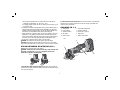
1
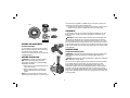
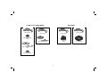
INSTRUCTION MANUAL
DC415-XE
HEAVY-DUTY 36V CORDLESS FINISHING GRINDER
1. WORK AREA
a. Keep work area clean and well lit. Cluttered and dark areas invite accidents.
b. Do not operate power tools in explosive atmospheres, such as in the
presence of flammable liquids, gases or dust. Power tools create sparks
which may ignite the dust or fumes.
c. Keep children and bystanders away while operating a power tool.
Distractions can cause you to lose control.
2. ELECTRICAL SAFETY
a. Power tool plugs must match the outlet. Never modify the plug in any
way. Do not use any adapter plugs with earthed (grounded) power tools.
Unmodified plugs and matching outlets will reduce risk of electric shock.
b. Avoid body contact with earthed or grounded surfaces such as pipes,
radiators, ranges and refrigerators. There is an increased risk of electric
shock if your body is earthed or grounded.
c. Do not expose power tools to rain or wet conditions. Water entering a power
tool will increase the risk of electric shock.
d. Do not abuse the cord. Never use the cord for carrying, pulling or
unplugging the power tool. Keep cord away from heat, oil, sharp edges
or moving parts. Damaged or entangled cords increase the risk of electric
shock.
e. When operating a power tool outdoors, use an extension cord suitable
for outdoor use. Use of a cord suitable for outdoor use reduces the risk of
electric shock.
3. PERSONAL SAFETY
a. Stay alert, watch what you are doing and use common sense when
operating a power tool. Do not use a power tool while you are tired or
under the influence of drugs, alcohol or medication. A moment of inattention
while operating power tools may result in serious personal injury.
b. Use safety equipment. Always wear eye protection. Safety equipment such
as dust mask, non-skid safety shoes, hard hat, or hearing protection used for
appropriate conditions will reduce personal injuries.
c. Avoid accidental starting. Ensure the switch is in the off position before
plugging in. Carrying power tools with your finger on the switch or plugging
in power tools that have the switch on invites accidents.
Definitions: Safety Guidelines
The definitions below describe the level of severity for each
signal word. Please read the manual and pay attention to
these symbols.
DANGER: Indicates an imminently hazardous situation
which, if not avoided, will result in death or serious injury.
WARNING: Indicates a potentially hazardous situation
which, if not avoided, could result in death or serious injury.
CAUTION: Indicates a potentially hazardous situation
which, if not avoided, may result in minor or moderate
injury.
CAUTION: Used without the safety alert symbol indicates a
potentially hazardous situation which, if not avoided, may
result in property damage.
IF YOU HAVE ANY QUESTIONS OR COMMENTS ABOUT THIS OR ANY DEWALT TOOL,
CALL US AT: 1800 654 155 (Aust) or 09 259 1111 (NZ).
SAFETY INSTRUCTIONS FOR POWER TOOLS
When using power tools, always observe the safety regulations applicable in your
country to reduce the risk of fire, electric shock and personal injury. Read the following
safety instructions before attempting to operate this product. Keep these instructions in
a safe place.
General Safety Rules
WARNING! Read all instructions. Failure to follow all instructions listed below
may result in electric shock, fire and/or serious injury. The term “power tool” in all
of the warnings listed below refers to your mains operated (corded) power tool or
battery operated (cordless) power tool.
SAVE THESE INSTRUCTIONS
1
5. BATTERY TOOL USE AND CARE
a. Ensure the switch is in the off position before inserting battery pack. Inserting
the battery pack into power tools that have the switch on invites accidents.
b. Recharge only with the charger specified by the manufacturer. A charger
that is suitable for one type of battery pack may create a risk of fire when
used with another battery pack.
c. Use power tools only with specifically designated battery packs. Use of any
other battery packs may create a risk of injury and fire.
d. When battery pack is not in use, keep it away from other metal objects like
paper clips, coins, keys, nails, screws, or other small metal objects that
can make a connection from one terminal to another. Shorting the battery
terminals together may cause burns or a fire.
e. Under abusive conditions, liquid may be ejected from the battery; avoid
contact. If contact accidentally occurs, flush with water. If liquid contacts
eyes, additionally seek medical help. Liquid ejected from the battery may
cause irritation or burns.
6. SERVICE
a. Have your power tool serviced by a qualified repair person using only
identical replacement parts. This will ensure that the safety of the power tool
is maintained.
d. Remove any adjusting key or wrench before turning the power tool on. A
wrench or a key left attached to a rotating part of the power tool may result in
personal injury.
e. Do not overreach. Keep proper footing and balance at all times. This
enables better control of the power tool in unexpected situations.
f. Dress properly. Do not wear loose clothing or jewellery. Keep your hair,
clothing and gloves away from moving parts. Loose clothes, jewellery or
long hair can be caught in moving parts.
g. If devices are provided for the connection of dust extraction and collection
facilities, ensure these are connected and properly used. Use of these
devices can reduce dust related hazards.
4. POWER TOOL USE AND CARE
a. Do not force the power tool. Use the correct power tool for your application.
The correct power tool will do the job better and safer at the rate for which it
was designed.
b. Do not use the power tool if the switch does not turn it on and off. Any
power tool that cannot be controlled with the switch is dangerous and must
be repaired.
c. Disconnect the plug from the power source before making any
adjustments, changing accessories, or storing power tools. Such preventive
safety measures reduce the risk of starting the power tool accidentally.
d. Store idle power tools out of the reach of children and do not allow
persons unfamiliar with the power tool or these instructions to operate the
power tool. Power tools are dangerous in the hands of untrained users.
e. Maintain power tools. Check for misalignment or binding of moving parts,
breakage of parts and any other condition that may affect the power tools
operation. If damaged, have the power tool repaired before use. Many
accidents are caused by poorly maintained power tools.
f. Keep cutting tools sharp and clean. Properly maintained cutting tools with
sharp cutting edges are less likely to bind and are easier to control.
g. Use the power tool, accessories and tool bits etc., in accordance with these
instructions and in the manner intended for the particular type of power tool,
taking into account the working conditions and the work to be performed.
Use of the power tool for operations different from those intended could result
in a hazardous situation.
Additional Safety Instructions
• Check that the grinding wheel backing flange has a yellow rubber ring (K)
installed, see Figure 3. Replace rubber ring if missing, damaged or worn. See
page 9 for details regarding proper accessory installation.
WARNING: The grinding wheel or accessory may loosen during coast-down of the
tool when shut off if rubber ring is missing or damaged. If grinding wheel or accessory
loosens, it may dismount from the machine and may cause serious personal injury.
• Always use proper guard with grinding wheel. A guard protects operator from
broken wheel fragments and wheel contact.
• Accessories must be rated for at least the speed recommended on the tool
warning label. Wheels and other accessories running over their rated speed can
fly apart and cause injury. Accessory ratings must always be above tool speed
as shown on tool nameplate.
2
• Hold tool by insulated gripping surfaces when performing an operation
where the cutting tool may contact hidden wiring. Contact with a “live” wire
will make exposed metal parts of the tool “live” and shock the operator.
• Do not use Type 11 (flaring cup) wheels on this tool. Using inappropriate
accessories can result in injury.
• Before using, inspect recommended accessory for cracks or flaws. If such a
crack or flaw is evident, discard the accessory. The accessory should also
be inspected whenever you think the tool may have been dropped. Flaws may
cause wheel breakage.
• Do not use circular saw blades or any other toothed blades with this tool.
Serious injury may result.
• When starting the tool with a new or replacement wheel, or a new or
replacement wire brush installed, hold the tool in a well protected area and
let it run for one minute. If the wheel has an undetected crack or flaw, it should
burst in less than one minute. If the wire brush has loose wires, they will be
detected. Never start the tool with a person in line with the wheel. This includes
the operator.
• Avoid bouncing the wheel or giving it rough treatment. If this occurs, stop the tool
and inspect the wheel for cracks or flaws.
• Direct sparks away from operator, bystanders or flammable materials. Sparks
may be produced while using a sander or grinder. Sparks may cause burns or
start fires.
• Always use side handle. Tighten the handle securely. The side handle should
always be used to maintain control of the tool at all times.
• Clean out your tool often, especially after heavy use. Dust and grit containing
metal particles often accumulate on interior surfaces and could create a hazard.
• Young children and the infirm. This appliance is not intended for use by
young children or infirm persons without supervision. Young children should be
supervised to ensure that they do not play with this appliance.
• Replacement of the supply cord. If the supply cord is damaged, it must be
replaced by the manufacturer or an authorised DEWALT Service Centre in order to
avoid a hazard.
WARNING: ALWAYS use safety glasses. Everyday eyeglasses are NOT safety
glasses. Also use face or dust mask if cutting operation is dusty. ALWAYS WEAR
CERTIFIED SAFETY EQUIPMENT:
• ANSI Z87.1 eye protection (CAN/CSA Z94.3),
• ANSI S12.6 (S3.19) hearing protection,
• NIOSH/OSHA/MSHA respiratory protection.
WARNING: Some dust created by power sanding, sawing, grinding, drilling, and
other construction activities contains chemicals known to cause cancer, birth defects
or other reproductive harm. Some examples of these chemicals are:
• lead from lead-based paints,
• crystalline silica from bricks and cement and other masonry products, and
• arsenic and chromium from chemically-treated lumber (CCA).
Your risk from these exposures varies, depending on how often you do this type of
work. To reduce your exposure to these chemicals: work in a well ventilated area, and
work with approved safety equipment, such as those dust masks that are specially
designed to filter out microscopic particles.
• Avoid prolonged contact with dust from power sanding, sawing, grinding,
drilling, and other construction activities. Wear protective clothing and wash
exposed areas with soap and water. Allowing dust to get into your mouth, eyes,
or lay on the skin may promote absorption of harmful chemicals.
WARNING: Use of this tool can generate and/or disburse dust, which may cause
serious and permanent respiratory or other injury. Always use NIOSH/OSHA approved
respiratory protection appropriate for the dust exposure. Direct particles away from
face and body.
WARNING: Always use eye protection. All users and bystanders must wear eye
protection that conforms to ANSI Z87.1.
CAUTION: When not in use, place tool on its side on a stable surface where it
will not cause a tripping or falling hazard. Some tools with large battery packs will
stand upright on the battery pack but may be easily knocked over.
WARNING: ALWAYS wear proper personal hearing protection that conforms to
ANSI S12.6 (S3.19) during use. Under some conditions and duration of use, noise
from this product may contribute to hearing loss.
3
• The label on your tool may include the following symbols. The symbols and their
definitions are as follows:
V ................. volts
A ...............amperes
Hz ............... hertz
W ..............watts
min ............. minutes
...........alternating current
no ..............no load speed
.......... direct current
.............. Class I Construction
.............earthing terminal
................... (grounded)
.............safety alert symbol
............... Class II Construction
…/min .......revolutions per minute
................... (double insulated)
BPM ..........beats per minute
• If battery contents come into contact with the skin, immediately wash area
with mild soap and water. If battery liquid gets into the eye, rinse water over the
open eye for 15 minutes or until irritation ceases. If medical attention is needed,
the battery electrolyte is composed of a mixture of liquid organic carbonates and
lithium salts.
• Contents of opened battery cells may cause respiratory irritation. Provide fresh
air. If symptoms persists, seek medical attention.
WARNING: Burn hazard. Battery liquid may be flammable if exposed to spark or
flame.
• Charge the battery packs only in DEWALT chargers.
• DO NOT splash or immerse in water or other liquids.
• Do not store or use the tool and battery pack in locations where the
temperature may reach or exceed 40˚C (105°F) (such as outside sheds or
metal buildings in summer).
WARNING: Never attempt to open the battery pack for any reason. If battery pack
case is cracked or damaged, do not insert into charger. Do not crush, drop or damage
battery pack. Do not use a battery pack or charger that has received a sharp blow, been
dropped, run over or damaged in any way (i.e., pierced with a nail, hit with a hammer,
stepped on). Damaged battery packs should be returned to service center for recycling.
WARNING: Fire hazard. Do not store or carry battery so that metal objects can
contact exposed battery terminals. For example, do not place battery in aprons,
pockets, tool boxes, product kit boxes, drawers, etc., with loose nails, screws, keys,
etc. Transporting batteries can possibly cause fires if the battery terminals
inadvertently come in contact with conductive materials such as keys, coins,
hand tools and the like. The US Department of Transportation Hazardous Material
Regulations (HMR) actually prohibit transporting batteries in commerce or on
airplanes (i.e., packed in suitcases and carry-on luggage) UNLESS they are properly
protected from short circuits. So when transporting individual batteries, make sure
that the battery terminals are protected and well insulated from materials that could
contact them and cause a short circuit.
Introduction
The DC9000-XE charger is designed to charge DEWALT battery packs in approximately
1 hour. This charger requires no adjustment and is designed to be as easy as possible
to operate. Simply place your battery pack into the receptacle of a plugged in charger
and it will automatically charge the pack.
Important Safety Instruction for Battery Packs
WARNING: For safe operation, read this manual and manuals originally supplied with
tool before using the charger.
When ordering replacement battery packs, be sure to include catalog number and
voltage. Consult the chart on the last page of this manual for compatibility of chargers
and battery packs.
The battery pack is not fully charged out of the carton. Before using the battery pack
and charger, read the safety instructions below. Then follow charging procedures
outlined.
READ ALL INSTRUCTIONS
• Do not incinerate the battery pack even if it is severely damaged or is
completely worn out. The battery pack can explode in a fire. Toxic fumes and
materials are created when lithium ion battery packs are burned.
• Do not charge or use battery in explosive atmospheres, such as in the
presence of flammable liquids, gases or dust. Inserting or removing the
battery from the charger may ignite the dust or fumes.
The RBRC™ Seal
TThe RBRC™ (Rechargeable Battery Recycling Corporation) Seal
on the lithium ion battery (or battery pack) indicates that the costs
to recycle the battery (or battery pack) at the end of its useful life
have already been paid by DEWALT.
4
• Pull by plug rather than cord when disconnecting charger. This will reduce
risk of damage to electric plug and cord.
• Make sure that cord is located so that it will not be stepped on, tripped over,
or otherwise subjected to damage or stress.
• Do not use an extension cord unless it is absolutely necessary. Use of improper
extension cord could result in risk of fire, electric shock, or electrocution.
• An extension cord must have adequate wire size (AWG or American Wire
Gauge) for safety. The smaller the gauge number of the wire, the greater the
capacity of the cable, that is 16 gauge has more capacity than 18 gauge.
When using more than one extension to make up the total length, be sure
each individual extension contains at least the minimum wire size.
MINIMUM GAGE FOR CORD SETS
For Cable length (m): 7.5
15
25
30
45
60
Use Cable with minimum rating (Amperes)
Tool Amperes
0 - 3.4
7.5
7.5
7.5
7.5
7.5
7.5
3.5 - 5.0
7.5
7.5
7.5
7.5
10
15
5.1 - 7.0
10
10
10
10
15
15
7.1 - 12.0
15
15
15
15
20
20
12.1 - 20.0
20
20
20
20
25
–
• Do not place any object on top of charger or place the charger on a soft
surface that might block the ventilation slots and result in excessive internal
heat. Place the charger in a position away from any heat source. The charger is
ventilated through slots in the top and the bottom of the housing.
• Do not mount charger on wall or permanently affix charger to any surface. The
charger is intended to use on a flat, stable surface (i.e., table top, bench top).
• Do not operate charger with damaged cord or plug — have them replaced
immediately.
• Do not operate charger if it has received a sharp blow, been dropped, or
otherwise damaged in any way. Take it to an authorized service center.
• Do not disassemble charger; take it to an authorized service center when
service or repair is required. Incorrect reassembly may result in a risk of
electric shock, electrocution or fire.
RBRC™ in cooperation with DEWALT and other battery users, has established
programs in the United States to facilitate the collection of spent lithium ion batteries.
Help protect our environment and conserve natural resources by returning the spent
lithium ion battery to an authorized DEWALT service center or to your local retailer for
recycling. You may also contact your local recycling center for information on where
to drop off the spent battery.
RBRC™ is a registered trademark of the Rechargeable Battery Recycling Corporation.
Storage Recommendations
1. The best storage place is one that is cool and dry away from direct sunlight and
excess heat or cold.
2. Long storage will not harm the battery pack or charger. Under proper conditions,
they can be stored for 5 years or more.
Important Safety Instructions for Battery Chargers
SAVE THESE INSTRUCTIONS: This manual contains important safety instructions for
battery chargers.
• Before using charger, read all instructions and cautionary markings on charger,
battery pack, and product using battery pack.
WARNING: Shock hazard. Do not allow any liquid to get inside charger.
CAUTION: Burn hazard. To reduce the risk of injury, charge only DEWALT batteries.
Other types of batteries may burst causing personal injury and damage.
CAUTION: Under certain conditions, with the charger plugged in to the power
supply, the charger can be shorted by foreign material. Foreign materials of a
conductive nature such as, but not limited to, steel wool, aluminum foil, or any
buildup of metallic particles should be kept away from charger cavities. Always
unplug the charger from the power supply when there is no battery pack in the cavity.
Unplug charger before attempting to clean.
• DO NOT attempt to charge the battery pack with any chargers other than the
ones in this manual. The charger and battery pack are specifically designed to
work together.
• These chargers are not intended for any uses other than charging DEWALT
rechargeable batteries. Any other uses may result in risk of fire, electric shock
or electrocution.
• Do not expose charger to rain or snow.
5
PROBLEM POWERLINE
When the charger is used with some portable power sources such as generators or
sources that convert DC to AC, the charger may temporarily suspend operation. The
three red lights will flash together with two fast blinks followed by a pause. This
indicates that the power souce is out of limits.
BAD BATTERY
The charger can detect a weak or damaged battery. The three red lights will flash
together with rapid blinking. The battery will no longer charge and should be returned
to a service center or a collection site for recycling.
BAD CHARGER
The charger will detect if it is not functioning properly. The three red lights will flash
together with one fast blink followed by a long blink. The charger will no longer work
and should be returned to an authorized service center or replaced.
LEAVING THE BATTERY IN THE CHARGER
The charger and battery pack can be left connected with the red lights glowing
indefinitely. The charger will keep the battery pack fresh and fully charged. This
charger features an automatic tune-up mode which equals or balances the individual
cells in the battery pack to allow it to function at peak capacity. Battery packs should
be tuned up weekly or whenever the battery no longer delivers the same amount of
work. To use the automatic tune-up mode, place the battery pack in the charger and
leave it for at least 8 hours.
• Disconnect the charger from the outlet before attempting any cleaning. This
will reduce the risk of electric shock. Removing the battery pack will not reduce
this risk.
• NEVER attempt to connect 2 chargers together.
• The charger is designed to operate on standard household electrical power.
Do not attempt to use it on any other voltage.
SAVE THESE INSTRUCTIONS
Charger
Your battery pack requires a 1 hour DEWALT charger. Be sure to read all safety
instructions before using your charger. Consult the chart on the back of this
manual for compatibility of chargers and battery packs.
Charging Procedure
1. Plug the charger into an appropriate outlet before
inserting the battery pack.
2. Insert the battery pack into the charger. The
charger is equipped with a three-light fuel gauge
that will blink according to the state of charge of
the battery pack.
3. The completion of charge is indicated by the three red lights remaining ON
continuously. The pack is fully charged and may be used at this time or left on
the charger.
0% - 33%
33% - 66%
66% - 99%
100%
Important Charging Notes
1. Longest life and best performance can be obtained if the battery pack is charged
when the air temperature is between 18°- 24°C (65°F and 75°F). DO NOT charge
the battery pack in an air temperature below +4.5°C (+40°F), or above +40.5°C
(+105°F). This is important and will prevent serious damage to the battery pack.
2. The charger and battery pack may become warm to touch while charging. This is
a normal condition, and does not indicate a problem. To facilitate the cooling of
the battery pack after use, avoid placing the charger or battery pack in a
warm environment such as in a metal shed, or an uninsulated trailer.
3. If the battery pack does not charge properly:
a. Check current at receptacle by plugging in a lamp or other appliance
b. Check to see if receptacle is connected to a light switch which turns power off
when you turn out the lights.
1st light blinks
1st light on, 2nd light blinks
1st, 2nd lights on, 3rd light blinks
1st, 2nd, 3rd lights on
Charger Diagnostics
This charger is designed to detect certain problems that can arise with the battery
packs or the charger. Problems are indicated by the three red lights flashing together
in different patterns.
6
To remove the battery pack from the tool, press the release button (J) and firmly pull
the battery pack out of the tool handle. Insert it into the charger as described in the
charger section of this manual.
c. Move charger and battery pack to a location where the surrounding air
temperature is approximately 18°- 24°C (65°F - 75°F).
d. If charging problems persist, take the tool, battery pack and charger to your
local service center.
4. The battery pack should be recharged when it fails to produce sufficient power on
jobs which were easily done previously. DO NOT CONTINUE to use under these
conditions. Follow the charging procedure. You may also charge a partially used
pack whenever you desire with no adverse affect on the battery pack.
5. Foreign materials of a conductive nature such as, but not limited to, steel wool,
aluminum foil, or any buildup of metallic particles should be kept away from
charger cavities. Always unplug the charger from the power supply when there
is no battery pack in the cavity. Unplug charger before attempting to clean.
6. Do not freeze or immerse charger in water or any other liquid.
WARNING: Shock hazard. Do not allow any liquid to get inside charger.
CAUTION: Never attempt to open the battery pack for any reason. If the plastic
housing of the battery pack breaks or cracks, return to a service center for recycling.
COMPONENTS (FIG. 2, 3)
A.
B.
C.
D.
E.
Trigger switch
Lock-Off Button
Spindle lock button
Side handle
Abrasive wheel
F.
G.
H.
I.
J.
Anti-lockup backing flange
Threaded clamp nut
Guard (Type 1, Type 27)
Battery pack
Battery release button
FIG. 2
B
I
C
INSTALLING AND REMOVING THE BATTERY PACK (FIG. 1)
NOTE: Make sure your battery pack is fully charged.
WARNING: To reduce the risk of serious personal injury, make certain the lockoff button (B), as shown under Components, is engaged to prevent switch
actuation before removing or installing battery.
E
D
FIG. 1
H
J
To install the battery pack into the tool handle, align the base of the tool with the
rails inside the tool’s handle and slide the battery pack firmly into the handle until you
hear the lock snap into place.
7
A
J
be serviced and re-assembled by a DEWALT service center. Failure to have the tool
serviced may cause brush, motor and bearing failure.
3. Re-install screws to attach the gear case to the motor housing. Tighten screws to
2.08 Nm (18 in-lbs.) torque. Overtightening could cause screws to strip.
FIG. 3
ACCESSORIES
F
It is important to choose the correct guards, backing pads and flanges to use with
grinder accessories. See pages 9 and 10 for information on choosing the correct
accessories.
WARNING: Accessories must be rated for at least the speed recommended on the
tool warning label. Wheels and other accessories running over their rated accessory
speed may fly apart and cause injury. Threaded accessories must have a 14 x 2 mm
hub. Every unthreaded accessory must have a 22.2 mm (7/8") arbor hole. If it does not,
it may have been designed for a circular saw. Use only the accessories shown on pages
9 and 10 of this manual. Accessory ratings must always be above tool speed as shown
on tool nameplate.
G
F
K
ASSEMBLY AND ADJUSTMENTS
ATTACHING SIDE HANDLE
The side handle (D) can be fitted to either side of the
gear case in the threaded holes. Before using the tool,
check that the handle is tightened securely.
To improve user comfort, the gear case will rotate 90˚
for cutting operations.
MOUNTING GUARD
MOUNTING AND REMOVING GUARD
WARNING: To reduce the risk of serious personal injury, turn tool off and and remove
battery pack before making any adjustments or removing/installing attachments or
accessories.
CAUTION: Guards must be used with all grinding wheels, cutting wheels, sanding flap
discs, wire brushes, and wire wheels.
The tool may be used without a guard only when sanding with conventional sanding
discs. DEWALT model DC415 is provided with a guard intended for use with
depressed center wheels (Type 27) and hubbed grinding wheels (Type 27). The
same guard is designed for use with sanding flap discs (Type 27 and 29) and wire
cup brushes. Grinding and cutting with wheels other than Type 27 and 29 require
different accessory guards included with tool. A Type 1 guard is provided for use with
a Type 1 wheel. Mounting instructions for these accessory guards are included in the
accessory package.
D
ROTATING THE GEAR CASE
WARNING: To reduce the risk of serious personal
injury, turn tool off and and remove battery pack
before making any adjustments or removing/installing
attachments or accessories.
1. Remove the four corner screws attaching the gear
case to motor housing.
2. Without separating the gear case from motor
housing, rotate the gear case head to desired
position.
NOTE: If the gear case and motor housing become
separated by more than 6.35 mm (1/4"), the tool must
8
115 mm (4-1/2") Grinding Wheels
Type 27 guard
Wire Wheels
Type 27 guard
Type 27 guard
Type 27 guard
Type 27 hubbed wheel
3" wire cup
brush
4" wire wheel
unthreaded backing
flange
Type 27 depressed center
wheel
threaded clamp nut
9
Sanding
Discs
115 mm (4-1/2")
Cutting Wheels
115 mm (4-1/2") Sanding
Flap Discs
rubber backing pad
Type 27 guard
sanding disc
threaded clamp nut
hubbed sanding flap
disc
Type 27 guard
Type 1 guard
Type 1 guard
unthreaded backing
flange
backing flange
backing flange
abrasive cutting wheel
diamond cutting wheel
clamp nut
clamp nut
non-hubbed sanding
flap disc
threaded clamp nut
10
OPERATION
1. Open the guard latch (L), and align the lugs (M) on the
M
guard with the slots (N) on the gear case.
2. Push the guard down until the guard lugs engage
and rotate freely in the groove on the gear case hub.
3. With the guard latch open, rotate the guard (H) into
the desired working position. The guard body should
be positioned between the spindle and the operator to N
provide maximum operator protection.
L
4. Close the guard latch to secure the guard on the
gear case. You should not be able to rotate the
guard by hand when the latch is closed. Do not
operate the grinder with a loose guard or the
clamp lever in open position.
5. To remove the guard, open the guard latch,
rotate the guard so that the lugs are aligned
H
with the slots and pull up on the guard.
NOTE: The guard is pre-adjusted to the diameter of
the gear case hub at the factory. If, after a period of
time, the guard becomes loose, tighten the
adjusting screw (O) with clamp lever in the closed
position with guard installed on the tool.
CAUTION: If the guard cannot be tightened by the
adjusting clamp, do not use the tool. To reduce the
risk of personal injury, take the tool and guard to a
O
service center to repair or replace the guard.
CAUTION: To reduce the risk of damage to the
tool, do not tighten the adjusting screw with the clamp lever in the open position.
Undetectable damage to the guard or the mounting hub may result.
NOTE: Edge grinding and cutting can be performed with Type 27 wheels designed
and specified for this purpose; 6.35 mm (1/4") thick wheels are designed for surface
grinding while 3.17 mm (1/8") wheels are designed for edge grinding. Cutting can
also be performed by using a Type 1 wheel and a Type 1 guard.
Switch
UNLOCKED
LOCK-OFF BUTTON AND TRIGGER SWITCH
Your cut-off tool is equipped with a lock-off
button (B).
To lock the trigger switch, press the lock-off
button as shown. When the lock-off button
B
is depressed to the lock icon, the unit is
locked.
Always lock the trigger switch when carrying
LOCKED
or storing the tool to eliminate unintentional
starting.
To unlock the trigger switch, press the
A
lock-off button. When the lock-off button is
depressed to the unlock icon, the unit is unlocked. The lock-off button is colored red
to indicate when the switch is in its unlocked position.
Pull the trigger switch (A) to turn the tool ON. Releasing the trigger switch turns the
tool OFF.
NOTE: This tool has no provision to lock the switch in the ON position, and should
never be locked ON by any other means.
CAUTION: Hold the side handle and body of the tool firmly to maintain control of
the tool at start up and during use and until the wheel or accessory stops rotating.
Make sure the wheel has come to a complete stop before laying the tool down.
CAUTION: Allow the tool to reach full speed before touching tool to the work
surface. Lift the tool from the work surface before turning the tool off.
SPINDLE LOCK
The spindle lock pin is provided to prevent the spindle from rotating when installing
or removing wheels. Operate the spindle lock pin only when the tool is turned off, the
battery is removed, and the wheel has come to a complete stop.
CAUTION: To reduce the risk of damage to the tool, do not engage the spindle lock
while the tool is operating. Damage to the tool will result and attached accessory may
spin off possibly resulting in injury.
11
To engage the lock, depress the spindle lock button and rotate the spindle until you
are unable to rotate the spindle further.
6.35 mm (1/4") WHEELS
raised section (pilot) fits into the center of the
wheel. If the wheel you are installing is 3.17 mm
(1/8") thick or less, place the threaded clamp nut
on the spindle so that the raised section (pilot) is
CLAMP NUT
not against the wheel.
4. While depressing the spindle lock button, tighten
the clamp nut with a wrench.
BACKING FLANGE
5. To remove the wheel, depress the spindle lock button
and loosen the threaded clamp nut with a wrench.
3.17 mm (1/8") WHEELS
NOTE: If the wheel spins after the clamp nut is
tightened, check the orientation of the threaded clamp
nut. If a thin wheel is installed with the pilot on the clamp
CLAMP NUT
nut against the wheel, it will spin because the height of
the pilot prevents the clamp nut from holding the wheel.
SURFACE GRINDING WITH GRINDING WHEELS
1. Allow the tool to reach full speed before touching the
BACKING FLANGE
tool to the work surface.
2. Apply minimum pressure to the work surface, allowing
the tool to operate at high speed. Grinding rate is
greatest when the tool operates at high speed.
3. Maintain a 20˚ to 30˚ angle between the tool and
20˚-30˚
work surface.
4. Continuously move the tool in a forward and back
motion to avoid creating gouges in the work surface.
5. Remove the tool from work surface before turning tool off. Allow the tool to stop
rotating before laying it down.
EDGE GRINDING WITH GRINDING WHEELS
WARNING: Wheels used for cutting and edge grinding may break or kick back if
they bend or twist while the tool is being used to do cut-off work or deep grinding. To
reduce the risk of serious injury, limit the use of these wheels with a standard Type
27 guard to shallow cutting and notching [less than 13 mm (1/2") in depth]. The
open side of the guard must be positioned away from the operator. For deeper cutting
with a Type 1 cut-off wheel, use a closed Type 1 guard. See pages 9 and 10 for more
information.
MOUNTING AND USING DEPRESSED CENTER GRINDING WHEELS
AND SANDING FLAP DISCS
MOUNTING AND REMOVING HUBBED WHEELS
WARNING: To reduce the risk of serious personal injury, turn tool off and and remove
battery pack before making any adjustments or removing/installing attachments or
accessories.
Hubbed wheels install directly on the 14 x 2 mm threaded spindle.
1. Thread the wheel on the spindle by hand.
2. Depress the spindle lock button and use a wrench to tighten the hub of the wheel.
3. Reverse the above procedure to remove the wheel.
CAUTION: Failure to properly seat the wheel before turning the tool on may result in
damage to the tool or the wheel.
MOUNTING NON-HUBBED WHEELS
WARNING: To reduce the risk of serious personal injury, turn tool off and and remove
battery pack before making any adjustments or removing/installing attachments or
accessories.
Depressed center Type 27 grinding wheels must be used with included flanges. See
pages 9 and 10 of this manual for more information.
F
1. Install the anti-lockup backing flange (F) on spindle
(P) with the raised section (pilot) against the wheel.
Be sure the backing flange recess is seated onto the
flats of the spindle by pushing and twisting the flange
before placing the wheel.
P
2. Place wheel against the backing flange, centering
the wheel on the raised section (pilot) of the backing
flange.
3. While depressing the spindle lock button, thread the
clamp nut (G) on spindle. If the wheel you are
installing is more than 3.17 mm (1/8") thick, place
the threaded clamp nut on the spindle so that the
G
12
1. Allow the tool to reach full speed before touching the tool to the work surface.
2. Apply minimum pressure to the work surface, allowing the tool to operate at high
speed. Grinding rate is greatest when the tool operates at high speed.
3. Position yourself so that the open-underside of the wheel is facing away from you.
4. Once a cut is begun and a notch is established in the workpiece, do not change
the angle of the cut. Changing the angle will cause the wheel to bend and may
cause wheel breakage. Edge grinding wheels are not designed to withstand side
pressures caused by bending.
5. Remove the tool from the work surface before turning the tool off. Allow the tool
to stop rotating before laying it down.
WARNING: Do not use edge grinding/cutting wheels for surface grinding
applications because these wheels are not designed for side pressures encountered
with surface grinding. Wheel breakage and serious personal injury may result.
SURFACE FINISHING WITH SANDING FLAP DISCS
1. Allow the tool to reach full speed before touching the tool to the work surface.
2. Apply minimum pressure to work surface, allowing the tool to operate at high
speed. Sanding rate is greatest when the tool operates at high speed.
3. Maintain a 5˚ to 10˚ angle between the tool and
work surface.
4. Continuously move the tool in a forward and
5˚-10˚
back motion to avoid creating gouges in the work
surface.
5. Remove the tool from work surface before turning tool off. Allow the tool to stop
rotating before laying it down.
MOUNTING SANDING BACKING PADS
WARNING: To reduce the risk of serious personal injury, turn tool off and and remove
battery pack before making any adjustments or removing/installing attachments or
accessories.
NOTE: Guard may be removed when using sanding backing pads
CAUTION: Proper guard must be reinstalled for grinding wheel, sanding flap disc,
wire brush or wire wheel applications after sanding applications are complete.
1. Place or appropriately thread backing pad (Q) on the spindle.
2. Place the sanding disc (R) on the backing pad (Q).
3. While depressing spindle lock, thread clamp nut
R
S
(S) on spindle, piloting the raised hub on the
clamp nut into the center of sanding disc and
backing pad.
4. Tighten the clamp nut by hand. Then depress
the spindle lock button while turning the sanding
disc until the sanding disc and clamp nut are
snug.
5. To remove the wheel, grasp and turn the backing
pad and sanding pad while depressing the
spindle lock button.
Q
USING SANDING BACKING PADS
Choose the proper grit sanding discs for your application. Sanding discs are available in
various grits. Coarse grits yield faster material removal rates and a rougher finish. Finer
grits yield slower material removal and a smoother finish.
Begin with coarse grit discs for fast, rough material removal. Move to a medium grit
paper and finish with a fine grit disc for optimal finish.
Coarse
16 - 30 grit
Medium
36 - 80 grit
Fine Finishing
100 - 120 grit
Very Fine Finishing
150 - 180 grit
1. Allow the tool to reach full speed before touching tool to the work surface.
2. Apply minimum pressure to work surface, allowing the tool to operate at high
speed. Sanding rate is greatest when the tool operates at high speed.
3. Maintain a 5˚ to 15˚ angle between the tool and
work surface. The sanding disc should contact
approximately 25.4 mm (1") of work surface.
5˚-15˚
4. Move the tool constantly in a straight line to prevent
burning and swirling of work surface. Allowing the
tool to rest on the work surface without moving, or
moving the tool in a circular motion causes burning and swirling marks on the
work surface.
5. Remove the tool from work surface before turning tool off. Allow the tool to stop
rotating before laying it down.
13
Precautions To Take When Sanding Paint
During clean up, children and pregnant women should be kept away from the
immediate work area.
3. All toys, washable furniture and utensils used by children should be washed
thoroughly before being used again.
1. Sanding of lead based paint is NOT RECOMMENDED due to the difficulty of
controlling the contaminated dust. The greatest danger of lead poisoning is to
children and pregnant women.
2. Since it is difficult to identify whether or not a paint contains lead without a
chemical analysis, we recommend the following precautions when sanding any
paint:
PERSONAL SAFETY
1. No children or pregnant women should enter the work area where the paint
sanding is being done until all clean up is completed.
2. A dust mask or respirator should be worn by all persons entering the work area.
The filter should be replaced daily or whenever the wearer has difficulty breathing.
NOTE: Only those dust masks suitable for working with lead paint dust and fumes
should be used. Ordinary painting masks do not offer this protection. See your
local hardware dealer for the proper N.I.O.S.H. approved mask.
3. NO EATING, DRINKING or SMOKING should be done in the work area to prevent
ingesting contaminated paint particles. Workers should wash and clean up
BEFORE eating, drinking or smoking. Articles of food, drink, or smoking should
not be left in the work area where dust would settle on them.
ENVIRONMENTAL SAFETY
1. Paint should be removed in such a manner as to minimize the amount of dust
generated.
2. Areas where paint removal is occurring should be sealed with plastic sheeting of
4 mils thickness.
3. Sanding should be done in a manner to reduce tracking of paint dust outside the
work area.
CLEANING AND DISPOSAL
1. All surfaces in the work area should be vacuumed and thoroughly cleaned daily
for the duration of the sanding project. Vacuum filter bags should be changed
frequently.
2. Plastic drop cloths should be gathered up and disposed of along with any dust
chips or other removal debris. They should be placed in sealed refuse receptacles
and disposed of through regular trash pick-up procedures.
MOUNTING AND USING WIRE BRUSHES AND WIRE WHEELS
Wire cup brushes or wire wheels screw directly on the grinder spindle without the use
of flanges. Use only wire brushes or wheels provided with a 14 x 2 mm threaded hub.
A Type 27 guard is required when using wire brushes and wheels.
CAUTION: To reduce the risk of personal injury, wear work gloves when handling wire
brushes and wheels. They can become sharp.
CAUTION: To reduce the risk of damage to the tool, wheel or brush must not touch guard
when mounted or while in use. Undetectable damage could occur to the accessory,
causing wires to fragment from accessory wheel or cup.
MOUNTING WIRE CUP BRUSHES AND WIRE WHEELS
WARNING: To reduce the risk of serious personal injury, turn tool off and and remove
battery pack before making any adjustments or removing/installing attachments or
accessories.
1. Thread the wheel on the spindle by hand.
2. Depress spindle lock button and use a wrench on the hub of the wire wheel or
brush to tighten the wheel.
3. To remove the wheel, reverse the above procedure.
CAUTION: To reduce the risk of damage to the tool, properly seat the wheel hub before
turning the tool on.
USING WIRE CUP BRUSHES AND WIRE WHEELS
Wire wheels and brushes can be used for removing rust, scale and paint, and for
smoothing irregular surfaces.
NOTE: The same precautions should be taken when wire brushing paint as when
sanding paint (Refer to Precautions To Take When Sanding Paint).
1. Allow the tool to reach full speed before touching the tool to the work surface.
2. Apply minimum pressure to work surface, allowing the tool to operate at high
speed. Material removal rate is greatest when the tool operates at high speed.
14
4. Close the guard latch to secure the on guard the
gear case cover. You should be unable to rotate
the guard by hand when the latch is in closed
position. Do not operate grinder with a loose
guard or clamp lever in open position.
5. To remove the guard, open the guard latch, rotate
H
the guard so that the lugs and slots are aligned
and pull up on the guard.
NOTE: The guard is pre-adjusted to the diameter of the
gear case hub at the factory. If, after a period of time, the
guard becomes loose, tighten the adjusting screw (O)
with the clamp lever in the closed position with guard
O
installed on the tool.
CAUTION: To reduce the risk of damage to the tool, do not
tighten adjusting screw with clamp lever in open position.
Undetectable damage to guard or mounting hub may
result.
MOUNTING CUTTING WHEELS
WARNING: To reduce the risk of serious personal injury, turn tool off and and remove
battery pack before making any adjustments or removing/installing attachments or
accessories.
CAUTION: Matching diameter threaded backing flange and clamp nut (included with
tool) must be used for cutting wheels.
1. Place the unthreaded backing flange on spindle with the raised section (pilot)
facing up. The raised section (pilot) on the backing flange will be against the
wheel when the wheel is installed. Be sure the backing flange recess is seated
onto the flats of the spindle by pushing and twisting the flange before placing the
wheel.
2. Place the wheel on the backing flange, centering the wheel on the raised section
(pilot).
3. Install the threaded clamp nut with the raised section (pilot) facing away from the
wheel.
4. Depress the spindle lock button and tighten clamp nut with a wrench.
5. To remove the wheel, grasp and turn while depressing the spindle lock button.
3. Maintain a 5˚ to 10˚ angle between the tool and work
surface for wire cup brushes.
4. Maintain contact between the edge of the wheel and
the work surface with wire wheels.
5. Continuously move the tool in a forward and back
5˚-10˚
motion to avoid creating gouges in the work surface.
Allowing the tool to rest on the work surface without
moving, or moving the tool in a circular motion causes burning and swirling
marks on the work surface.
6. Remove the tool from the work surface before turning the tool off. Allow the tool
to stop rotating before setting it down.
CAUTION: Use extra care when working over an edge, as a sudden sharp
movement of grinder may be experienced.
MOUNTING AND USING CUTTING (TYPE 1) WHEELS
Cutting wheels include diamond wheels and abrasive discs. Abrasive cutting wheels
for metal and concrete use are available. Diamond blades for concrete cutting can
also be used.
WARNING: A closed, 2-sided cutting wheel guard is included with this tool and is
required when using cutting wheels. Failure to use proper flange and guard can result
in injury resulting from wheel breakage and wheel contact. See pages 9 and 10 for
more information.
MOUNTING CLOSED (TYPE 1) GUARD
U
WARNING: To reduce the risk of serious personal
injury, turn tool off and and remove battery pack
before making any adjustments or removing/installing
attachments or accessories.
1. Open the guard latch (L), and align the lugs (T) on
T
the guard with the slots on the hub (U).
L
2. Push the guard down until the guard lug engages
and rotates freely in the groove on the gear case hub.
3. Rotate guard (H) into desired working position. The guard body should be positioned
between the spindle and the operator to provide maximum operator protection.
15
•
USING CUTTING WHEELS
WARNING: Do not use edge grinding/cutting wheels for surface grinding applications
because these wheels are not designed for side pressures encountered with surface
grinding. Wheel breakage and injury may result.
1. Allow tool to reach full speed before touching tool to work surface.
2. Apply minimum pressure to work surface, allowing tool to operate at high speed.
Cutting rate is greatest when the tool operates at high speed.
3. Once a cut is begun and a notch is established in the workpiece, do not change
the angle of the cut. Changing the angle will cause the wheel to bend and may
cause wheel breakage.
4. Remove the tool from work surface before turning tool off. Allow the tool to stop
rotating before setting it down.
Support large panels to minimize the risk of wheel pinching and kickback.
Large panels tend to sag under their own weight. Support must be placed under
the panel on both sides, near the line of cut and near the edge of the panel.
MAINTENANCE
WARNING: Shock Hazard. To reduce the risk of serious personal injury, turn
tool off and disconnect tool from power source before making any adjustments or
removing/installing attachments or accessories.
Cleaning
WARNING: Blow dirt and dust out of all air vents with clean, dry air at least once
a week. To minimize the risk of eye injury, always wear ANSI Z87.1 approved eye
protection when performing this.
CAUTION: Never use solvents or other harsh chemicals for cleaning the nonmetallic parts of the tool. These chemicals may weaken the plastic materials used in
these parts. Use a cloth dampened only with water and mild soap. Never let any liquid
get inside the tool; never immerse any part of the tool into a liquid.
Causes and Operator Prevention of Kickback
• Kickback is a sudden reaction to a pinched, bound or misaligned wheel, wire
brush or flap disc causing an uncontrolled cut-off tool to lift up and out of the
workpiece toward the operator.
• When the wheel is pinched or bound tightly by the workpiece, the wheel stalls
and the motor reaction drives the unit rapidly back toward or away from the
operator.
• Kickback is the result of tool misuse and/or incorrect operating procedures or
conditions and can be avoided by taking proper precautions as given below:
• Maintain a firm grip with both hands on the unit and position your body and
arm to allow you to resist kickback forces. Kickback forces can be controlled
by the operator, if proper precautions are taken.
• When wheel is binding, or when interrupting a cut for any reason, release the
trigger and hold the unit motionless in the material until the wheel comes to a
complete stop. Never attempt to remove the unit from the work or pull the unit
backward while the wheel is in motion or kickback may occur. Investigate and
take corrective actions to eliminate the cause of wheel binding.
• When restarting a cut-off tool in the workpiece, check that the wheel is not
engaged into the material. If wheel is binding, it may walk up or kickback from
the workpiece as the tool is restarted.
CHARGER CLEANING INSTRUCTIONS
WARNING: Shock hazard. Disconnect the charger from the AC outlet before
cleaning. Dirt and grease may be removed from the exterior of the charger using a
cloth or soft non-metallic brush. Do not use water or any cleaning solutions.
Lubrication
Your tool was properly lubricated before leaving the factory. In from two to six
months, depending upon use, take or send your tool to an authorized service
center for a complete cleaning, inspection and lubrication. Tools used constantly on
production jobs will need relubrication more often. Also, tools “out of service” for long
periods should be relubricated before being put back to work.
Repairs
This charger is not user serviceable. There are no user serviceable parts inside the
charger. Servicing at an authorized service center is required to avoid damage to static
sensitive internal components.
16
To assure product SAFETY and RELIABILITY, repairs, maintenance and adjustment
(including brush inspection and replacement) should be performed by certified
service centers or other qualified service organizations, always using identical
replacement parts.
In addition to the warranty, DEWALT tools are covered by our:
FREE ONE YEAR SERVICE CONTRACT
DEWALT will also maintain the tool for free at any time during the first year of
purchase. This includes labour, parts and lubrication required to restore the product to
sound mechanical and/or electrical condition. Normal wear parts are not covered in
this service. Carbon brushes worn more then 50% will be replaced.
NOTE: Three Year Warranty is not applicable to items deemed as consumables. Radial
arm saws are covered by a one (1) year warranty only. DEWALT Reserves the right to
review its warranty policy prior to launch of any new business development products.
30 DAY NO SATISFACTION GUARANTEE
If you are dissatisfied with any DEWALT power tool, laser or nailer, for any reason,
simply return it to the point of purchase with your sales receipt within 30 days for a
replacement unit or a full refund.
FREE WARNING LABEL REPLACEMENT: If your warning labels become illegible or
are missing, call (AUS) 1800 654 155 or (NZ) 09 259 1111 for a free replacement.
ACCESSORIES
WARNING: Since accessories, other than those offered by DEWALT, have not been
tested with this product, use of such accessories with this tool could be hazardous.
To reduce the risk of injury, only DEWALT, recommended accessories should be used
with this product.
Recommended accessories for use with your tool are available at extra cost from
your local service center. If you need any assistance in locating any accessory,
please contact DEWALT Industrial Tool Co., 20 Fletcher Road, Mooroolbark, VIC 3138
Australia or call 1800 654 155 or (NZ) 09 259 1111.
Guarantee
Applicable to hand held Power Tools, Lasers and Nailers.
Three Year Limited Warranty
DEWALT will repair, without charge, any defects due to faulty materials or
workmanship for three years from the date of purchase. Please return the complete
unit, transportation prepaid, to any DEWALT Service Centre, or any authorised
service station.
For warranty repair information, call (AUS) 1800 654 155 or (NZ) 09 259 1111.
This warranty does not apply to
• Accessories
• Damage caused where repairs have been made or attempted by others.
• Damage due to misuse, neglect, wear and tear, alteration or modification.
This warranty gives you specific legal rights and you may have other rights under the
provisions of the Consumer Guarantee Act 1993 (New Zealand only), Trade Practices
Act 1974 and State Legislation (Australia only).
17
DEWALT Battery and Charger Systems
Battery
Output
Nominal
Chargers/Charge Time
240 Volts
12 Volts
Cat. Number
Voltage
Amp Hour
97014
98014
DW9106
DW9107
DW9108
DW9115
DW9116
DW9117
DW9118
DE9116
DE9118
DW911
DC011
DW0245
DE2046
DE9000
DW9109
DW0242
DE0240-XJ
DW0240
DW9096
DE9095-XJ
DE9091-XJ
DW9091
DC9071
DE9074-XJ
DW9072
DE9071-XJ
DW9071
DW9050
DW9063
DW9062
DW9061
DW9048
DW9057
DW9046
DC9096
DC9091
DC9036
24
24
24
18
18
14.4
14.4
12
12
12
12
12
12
9.6
9.6
9.6
9.6
7.2
7.2
18
14.4
36
2.0
2.0
1.7
2.4
2.0
2.0
1.7
2.4
1.25
1.2
2.0
1.7
1.3
1.25
1.3
1.7
1.3
1.25
1.3
2.4
2.4
X
X
X
X
X
X
45
45
60
45
45
60
60
40
45
45
60
40
45
40
X
60
X
X
X
X
X
X
45
45
60
45
45
60
60
40
45
45
60
40
45
40
X
60
X
X
X
X
X
X
45
45
60
45
45
60
60
40
45
45
60
40
45
40
X
60
X
X
X
X
X
X
45
45
60
30
30
45
45
X
30
30
45
X
30
X
X
60
X
X
X
X
60
60
45
45
60
30
30
45
45
X
30
30
45
X
30
X
60
60
X
X
X
X
X
X
15
15
15
15
15
15
15
15
15
15
15
15
15
15
X
15
X
X
X
X
60
60
45
45
60
30
30
45
45
X
30
30
45
X
30
X
60
60
X
X
X
X
20
20
15
15
15
12
12
15
15
X
12
12
15
X
12
X
20
15
X
X
X
X
X
X
90
90
60
60
60
90
90
X
60
60
90
X
60
X
X
60
X
X
X
X
60
60
45
45
60
30
30
45
45
X
30
30
45
X
30
X
60
60
X
X
X
X
X
X
90
90
60
60
60
90
90
X
60
60
90
X
60
X
X
60
X
X
X
X
60
60
45
45
60
30
30
45
45
X
30
30
45
X
30
X
60
60
X
X
X
X
60
60
45
45
60
30
30
45
45
X
30
30
45
X
30
X
60
60
X
60
60
60
X
X
X
X
X
X
X
X
X
X
X
X
X
X
X
X
X
X
X
60
60
60
X
X
X
X
X
X
X
X
X
X
X
X
X
X
X
X
X
X
X
X
X
X
X
X
X
X
X
X
X
X
X
X
X
X
X
X
X
X
X
X
60
X
X
X
60
60
45
45
60
30
30
45
45
X
30
30
45
X
30
X
60
60
X
X Indicates that the battery pack is not compatible with that specific charger.
All charge times are approximate. Actual charge time may vary.
Read the instruction manual for more specific information.
The battery voltage is nominal, it can measure above or below depending on the state of charge.
DEWALT Industrial Tool Co.,
20 Fletcher Road, Mooroolbark, VIC 3138 Australia (03 8720 5100) • 5 Te Apunga Place, Mt Wellington, New Zealand (09 259 1111)
(MAY07)
Form No. 652070-00
DC415-XE
Copyright © 2007 DEWALT
The following are trademarks for one or more DEWALT power tools: the yellow and black color scheme; the “D” shaped air intake grill; the array of pyramids on the handgrip;
the kit box configuration; and the array of lozenge-shaped humps on the surface of the tool.