1
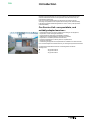
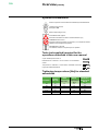
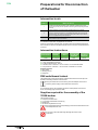
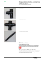
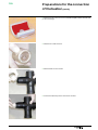
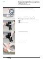
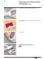
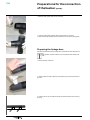
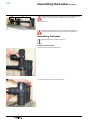
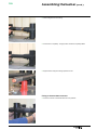
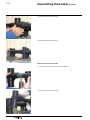
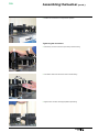
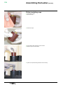
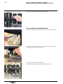
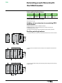
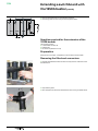
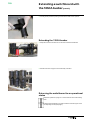
Medium Voltage Distribution FBX Assembling a 1250A busbar Instructions www.schneider-electric.com FBX Contents ■■ Introduction��������������������������������������������������������������������������������������������������������� 3 □□ Our Service Unit: our specialists, and suitably adapted services...��������������� 3 ■■ Overview�������������������������������������������������������������������������������������������������������������� 4 □□ Eco-design concept and valorization of the materials ���������������������������������� 4 □□ Responsibilities���������������������������������������������������������������������������������������������� 4 □□ Particular instructions for operations and interventions on energized equipment�� 4 □□ Other technical notices to be consulted��������������������������������������������������������� 4 □□ Symbols & conventions���������������������������������������������������������������������������������� 5 □□ Tools (not supplied) required for the operations described in this user manual��������������������������������������������������������������������������������������������������������������� 5 □□ Tightening torque values [Nm] for standard assemblies�������������������������������� 5 ■■ Preparations for the connection of the busbar ���������������������������������������������� 6 □□ Intervention levels������������������������������������������������������������������������������������������ 6 □□ Intervention Instructions��������������������������������������������������������������������������������� 6 □□ FBX switchboard lockout������������������������������������������������������������������������������� 6 □□ Supplies required for the assembly of the 1250A busbar������������������������������ 6 □□ Switchboard status����������������������������������������������������������������������������������������� 7 □□ The principles of fitting the busbar����������������������������������������������������������������� 7 □□ Preparing an intermediate connector������������������������������������������������������������� 8 □□ Preparing an end-piece connector��������������������������������������������������������������� 10 □□ Preparing the linkage bars��������������������������������������������������������������������������� 12 ■■ Assembling the busbar������������������������������������������������������������������������������������ 13 □□ Preparing the switchboard��������������������������������������������������������������������������� 13 □□ Assembling the busbar�������������������������������������������������������������������������������� 14 • Fitting an end connector����������������������������������������������������������������������������� 14 • Fitting an intermediate connector��������������������������������������������������������������� 15 • Fit the second end connector��������������������������������������������������������������������� 16 • Tightening the connectors��������������������������������������������������������������������������� 17 □□ Fit the insulating caps���������������������������������������������������������������������������������� 18 □□ Fitting the sealing covers and cleaning the bars����������������������������������������� 19 □□ Connecting the earthing braids�������������������������������������������������������������������� 20 ■■ Extending a switchboard with the 1250A busbar����������������������������������������� 21 □□ Intervention Instructions������������������������������������������������������������������������������� 21 □□ FBX switchboard lockout����������������������������������������������������������������������������� 21 □□ Addition of an extension to an existing FBX switchboard���������������������������� 21 □□ Earthing existing busbars����������������������������������������������������������������������������� 21 □□ Supplies required for the extension of the 1250A busbar���������������������������� 22 □□ Preparation��������������������������������������������������������������������������������������������������� 22 □□ Removing the fitted end connectors������������������������������������������������������������ 22 □□ Extending the 1250 A busbar����������������������������������������������������������������������� 23 □□ Returning the switchboard to an operational status������������������������������������ 23 2 AMTNoT174-02 FBX Introduction Operations and maintenance may only be carried out by personnel who have received suitable authorisation for the operations and manoeuvres they are responsible for performing. If this is not the case, please refer to our Service Unit or Training Centre. All locking-out operations must be performed according to the "General Safety Instructions booklet for Electrical Applications" UTE C 18 510 (or its equivalent outside FRANCE). Our Service Unit: our specialists, and suitably adapted services... ■■ Guarantee extension contracts in relation to the selling of new equipment, ■■ Supervision of HVA switchgear installations, ■■ Technical advice, diagnoses of the facilities, expertise, ■■ Maintenance contracts adapted to operational constraints, ■■ Systematic or conditional preventive maintenance, ■■ Corrective maintenance in case of partial or complete failure, ■■ Supply of spare parts, ■■ Overhauling of equipment and requalification of installations in order to benefit from new technologies and extend the life of your switchgear by limited investments. Contact the Schneider Electric Service Unit for diagnoses and advice: Working hours or AMTNoT174-02 33 (0)3 85 29 35 00 33 (0)3 85 29 36 30 33 (0)3 85 29 36 43 3 FBX Overview © - Schneider Electric - 2010. Schneider Electric, the Schneider Electric logo and their figurative forms are Schneider Electric registered trademarks. The other brand names mentioned within this document, whether they be copyright or not, belong to their respective holders. Eco-design concept and valorization of the materials The design and life cycle of the equipment and switchgear manufactured by Schneider Electric take environmental requirements into account (see § 7). The design and manufacture of our packaging are both in conformity with the French government decree N° 98-638 of 20 July 1998, concerning the account that is taken of environmental requirements. Responsibilities Our devices are quality controlled and tested at the factory in accordance with the standards and the regulations currently in force. Apparatus efficiency and apparatus life depend on the compliance with the installation, commissioning and operation instructions described in this user manual. Non respect of these instructions is likely to invalidate any guarantee. Local requirements especially about safety and which are in accordance with the indications given in this document, must be observed. Schneider Electric declines any responsibility for the consequences: ■■ due to the non respect of the recommendations in this manual which make reference to the international regulations in force, ■■ due to the non respect of the instructions by the suppliers of cables and connection accessories during installation and fitting operations, ■■ of any possible aggressive climatic conditions (humidity, pollution, etc.) acting in the immediate environment of the materials that are neither suitably adapted nor protected for these effects. This user manual does not list the locking-out procedures that must be applied. The interventions described are carried out on de-energized equipment (in the course of being installed) or locked out (non operational). Particular instructions for operations and interventions on energized equipment The technical performances specified by Schneider Electric must be respected. To do this, please see the Technical Characteristics Manual. When commissioning and operating the equipment under normal conditions, the General safety instructions for electrical applications must be respected, (protective gloves, insulating stool, etc.), in addition to standard operating instructions. All manipulations must be completed once started. The durations (for completing the operations mentioned) given in the maintenance tables are purely an indication and depend on on-site conditions. Other technical notices to be consulted ■■ AMTNoT110-02 ■■ AMTNoT131-02 ■■ AMTNoT132-02 4 FBX FBX (IS) FBX (IS) Guide to Civil Engineering Work Installation - Commissioning Operation - Maintenance AMTNoT174-02 FBX Overview (contd.) Symbols & conventions Code for a product recommended and marketed by Schneider Electric 21 Nm Tightening torque value Example: 21 Nm Mark corresponding to a key CAUTION! Remain vigilant! Precautions to be taken in order to avoid accidents or injury FORBIDDEN! Do not do it! Compliance with this indication is compulsory, non compliance with this stipulation may damage the equipment. INFORMATION - ADVICE Your attention is drawn to a specific point or operation Tools (not supplied) required for the operations described in this user manual 2 open-ended spanners size 10 Ratchet wrench + extension + 10 mm socket + 19 mm extended socket Torque wrench + extension + 10 mm socket + extended 19 m socket Large, flat-headed screwdriver Tightening torque values [Nm] for standard assemblies AMTNoT174-02 Diameter Plastic (PA 6.6) M6 0.8 Steel Class < 8.8 4.3 Class ≥ 8.8 ≤ 10.9 Fasteners with grease A2-70 8.8 6.6 Steel M8 1.8 10.5 21.0 15.8 M 10 3.5 14.0 42.0 35.0 M 12 6.0 - 70.0 60.0 M 16 12.0 - 170.0 134 5 FBX Preparations for the connection of the busbar Intervention levels Levels Definition 1 Operations as noted as instructions in the "Operation - Maintenance" notice, carried out by trained personal capable of intervening whilst respecting the rules of security. 2 Complex operations, requiring specific expertise and the use of support equipment in accordance with the constructor's procedures. These are carried out by the constructor himself or by a specialised technician who has received regular training by the constructor as part of the implementation of procedures and who is equipped with specific equipment. 3 All preventive and corrective maintenance, all renovation and reconstruction work is carried out by the constructor. Extensions may be put together by personnel qualified in HVA equipment and HVA/ LV substation interventions, equipped with this manual. Apart from mechanical assembly skills, the electro-technical knowledge required for the connections is similar to the skills required for the connection of a separable HVA connector. Intervention Instructions Intervention Busbar Cables Load-break switches Earthing switches Level 1 De-energized De-energized Open Closed Tools required: ■■ 1 Large, flat-headed screwdriver ■■ 2 x open-ended spanners - size 10 ■■ 1 ratchet wrench + extension + 10 mm socket + 19 mm extended socket ■■ 1 torque wrench + extension + 10 mm socket + extended 19 m socket Products required: ■■ Clean cloths ■■ Cleaning solvent ■■ Soft gloves FBX switchboard lockout The switchboard must be de-energised, all load-break switches must be open and earthed; the earthing switches must be closed. During the intervention, the time during which the adapter cones are not covered by their end plug must be reduced to a minimum. If, for whatever reason, the installation operation is interrupted for more than 24 hours, the blanking plugs must be re-fitted. Supplies required for the assembly of the 1250A busbar The supplies comprise: ■■ 2 end-piece connector kits ■■ 1 (or several) intermediate connector(s) ■■ linkage bars ■■ This document (AMTNoT174-02) The accessories boxes and the packaging around the busbar itself must be removed/opened with care. Do not use a cutter if its blade might damage the surface of the components. 6 AMTNoT174-02 FBX Preparations for the connection of the busbar (contd.) ■■ End connector. ■■ Intermediate connector. ■■ Linkage bar (2 different lengths). Switchboard status Before any interventions on the busbar, the switchboard must be installed in its final location, coupled and fixed to the floor. The busbar must be the last component fitted during the assembly operation. The switchboard must not be energised before the busbar is fitted. The principles of fitting the busbar Start by the complete assembly of the rear-most phase. For ease of photography and clarity of the operations, the description of the assembly process has been shown using the phase nearest the front of the unit. AMTNoT174-02 7 FBX Preparations for the connection of the busbar (contd.) Preparing an intermediate connector This operation must be carried out in a dust, pollution and humidity-free area. ■■ Clean the four connector apertures. ■■ Use the grease provided in packing to lubricate the inside of each aperture. ■■ Clean the two contact shells. ■■ Apply a film of grease to the contact shells (see following image). 8 AMTNoT174-02 FBX Preparations for the connection of the busbar (contd.) ■■ Grease the whole surface of each shell, with the exception of the concave side (in red on the image). ■■ Assemble the 2 shells as shown. ■■ Slide the shells into the connector. ■■ Push the shell assembly into the centre of the connector. AMTNoT174-02 9 FBX Preparations for the connection of the busbar (contd.) ■■ The passage holes must be centred within the connector. Preparing an end-piece connector This operation must be carried out in a dust, pollution and humidity-free area. ■■ Clean the three connector apertures. ■■ Grease the inside of each aperture. ■■ Clean the two contact shells. 10 AMTNoT174-02 FBX Preparations for the connection of the busbar (contd.) ■■ Apply a film of grease to the contact shells (see following image). ■■ Grease the whole surface of each shell, with the exception of the concave side (in red on the image). ■■ Clean the spacer. ■■ Assemble the 2 shells, and the spacer, as shown. This spacer must be fitted to each end piece. AMTNoT174-02 11 FBX Preparations for the connection of the busbar (contd.) ■■ Slide the shells, spacer first, into the connector. ■■ Push the shell+spacer assembly down to the base of the connector. ■■ Make sure that the passage hole is centred within the connector (See page 8). Preparing the linkage bars Check the lengths of the bars by holding them up between the mounting points on the bushing. This operation must be carried out in a dust, pollution and humidity-free area. ■■ Clean both ends of each bar. ■■ Use the grease provided in packing to lubricate the grey zones at both ends of each bar. ■■ Pose the bars on two small blocks to keep the greased sections from touching anything. 12 AMTNoT174-02 FBX Assembling the busbar Preparing the switchboard ■■ Remove the protective cover from all the bushing on a single phase. ■■ Clean each bushing. ■■ Use the grease provided in packing to grease each bushing. 10 Nm AMTNoT174-02 ■■ Screw the fastening rod onto each bushing. ■■ Tighten all rods to the correct torque level. 13 FBX Assembling the busbar (contd.) 369 499 Before assembling the busbars, check the centre to centre dimensions of the rods in order to ensure correct assembly of the switchboard. Tolerance: 0/+3mm If the centre to centre dimension of the busbars is out of tolerance, dismantle again and proceed with a new assembly of the functions. Assembling the busbar Start the assembly of the busbar at one end. Fitting an end connector ■■ Place the end-connector onto the bushing. ■■ Push the connector firmly down onto the bushing. 14 AMTNoT174-02 FBX Assembling the busbar (contd.) ■■ Fit the linkage bar into its housing. ■■ Push the bar in completely. The grey section should be completely hidden. ■■ Support the bar using the bushing's protective cover. Fitting an intermediate connector ■■ Push the connector onto the lateral bar as far as possible. AMTNoT174-02 15 FBX Assembling the busbar (contd.) ■■ Position the connector on the bushing. ■■ Insert the second bar into its housing. Fit the second end connector ■■ Push the connector onto the lateral bar as far as possible. ■■ Position the connector on the bushing. 16 AMTNoT174-02 FBX Assembling the busbar (contd.) ■■ Position the connectors on a slope for this operation. Tightening the connectors ■■ Press firmly on each connector to push it fully onto its bushing. ■■ Fit a washer then screw a bolt onto each connector fitting. ■■ Tighten each connector to the appropriate torque setting. 50 Nm AMTNoT174-02 17 FBX Assembling the busbar (contd.) Fit the insulating caps ■■ Use protective gloves. ■■ Clean the 3 caps. ■■ Grease the 3 caps. ■■ Insert a Rilsan collar vertically into the connector. ■■ Slide the cap into its final location. ■■ Tighten the cap whilst holding the Rilsan collar vertically. 18 AMTNoT174-02 FBX Assembling the busbar (contd.) ■■ Loosen the cap by one turn. ■■ Remove the Rilsan collar. ■■ Re-tighten the cap to the required torque setting. ■■ Clean any excess grease from the cap. 30 Nm Fitting the sealing covers and cleaning the bars ■■ Check, one final time, that the cap is correctly fitted. ■■ Clip the sealing cover onto each connector. AMTNoT174-02 19 FBX Assembling the busbar (contd.) ■■ Clean off any residual grease on the bars and connectors. Connecting the earthing braids ■■ Connect an earthing braid to each connector (2 x 10 mm open-ended spanners). 8.8 Nm ■■ Gather all three braids on a single function together and connect them to earth using a bolt (2 x 10 mm open-ended spanners). 8.8 Nm ■■ The earthing braids are now connected to earth. ■■ Make sure that the bushing earthing braids are connected correctly. 20 AMTNoT174-02 FBX Extending a switchboard with the 1250A busbar Intervention Instructions Intervention Busbar Cables Load-break switches Earthing switches Level 1 De-energized and earthed. De-energized Open Closed FBX switchboard lockout See instructions in § 6. Addition of an extension to an existing FBX switchboard Install the extension function in its definitive location. Couple the extension to the switchboard Fix the cubicle to the floor (see corresponding manual - § 2.4). The busbar must be the last component fitted during the assembly operation. Earthing existing busbars ■■ Couple the extension function to the FBX switchboard then fix it down to the floor. ■■ Disconnnect the 3 cables from the functional unit non-adjacent to the extension function. ■■ Connect a removable earthing device (earthing block) linking the three bushings straight to earth. AMTNoT174-02 21 FBX Extending a switchboard with the 1250A busbar (contd.) ■■ Close the load-break switch on the earthed functional unit. ■■ Use warning panels to inform everyone of the equipment status. Supplies required for the extension of the 1250A busbar The supplies comprise: ■■ 1 intermediate connector kit ■■ 3 linkage bars ■■ This document (AMTNoT174-02) Preparation See instructions in chapter " Preparations for the connection of the busbar" . Removing the fitted end connectors ■■ Carefully disassemble the fitted connectors as they will be re-used at the end of the switchboard. ■■ Use protective gloves. ■■ Clean the apertures of the three dismantled connectors using a suitable solvent. 22 AMTNoT174-02 FBX Extending a switchboard with the 1250A busbar (contd.) ■■ Use the grease provided in packing to lubricate the inside of each aperture. Extending the 1250 A busbar ■■ Keep hold of the end connectors to re-use at the end of the switchboard. ■■ See the instructions in page 21 for the assembly of the bars. Returning the switchboard to an operational status Repeat the operations in page 21 in reverse order to remove the earthing block. Energise the switchboard in accordance with the instructions given in the corresponding manual (See page 4). AMTNoT174-02 23 © 2010 Schneider Electric - All rights reserved Schneider Electric 35, rue Joseph Monier CS 30323 92506 Rueil-Malmaison Cedex, France RCS Nanterre 954 503 439 Capital social 896 313 776 € www.schneider-electric.com AMTNoT174-02 As standards, specifications and designs change from time to time, please ask for confirmation of the information given in this publication. This document has been printed on ecological paper Publishing: Schneider Electric Design: Schneider Electric Printing 12-2010