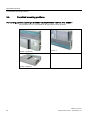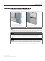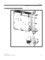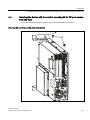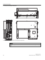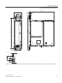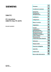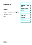
1
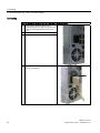
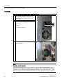
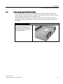
SIMATIC IPC627C 1 ___________________ Introduction 2 ___________________ Description SIMATIC Industrie PC SIMATIC IPC627C 3 ___________________ Application planning 4 ___________________ Mounting 5 ___________________ Connecting 6 ___________________ Commissioning Getting Started 7 ___________________ Troubleshooting 8 ___________________ Dimensional drawings A ___________________ Appendix 09/2011 A5E02669077-03 Legal information Legal information Warning notice system This manual contains notices you have to observe in order to ensure your personal safety, as well as to prevent damage to property. The notices referring to your personal safety are highlighted in the manual by a safety alert symbol, notices referring only to property damage have no safety alert symbol. These notices shown below are graded according to the degree of danger. DANGER indicates that death or severe personal injury will result if proper precautions are not taken. WARNING indicates that death or severe personal injury may result if proper precautions are not taken. CAUTION with a safety alert symbol, indicates that minor personal injury can result if proper precautions are not taken. CAUTION without a safety alert symbol, indicates that property damage can result if proper precautions are not taken. NOTICE indicates that an unintended result or situation can occur if the relevant information is not taken into account. If more than one degree of danger is present, the warning notice representing the highest degree of danger will be used. A notice warning of injury to persons with a safety alert symbol may also include a warning relating to property damage. Qualified Personnel The product/system described in this documentation may be operated only by personnel qualified for the specific task in accordance with the relevant documentation, in particular its warning notices and safety instructions. Qualified personnel are those who, based on their training and experience, are capable of identifying risks and avoiding potential hazards when working with these products/systems. Proper use of Siemens products Note the following: WARNING Siemens products may only be used for the applications described in the catalog and in the relevant technical documentation. If products and components from other manufacturers are used, these must be recommended or approved by Siemens. Proper transport, storage, installation, assembly, commissioning, operation and maintenance are required to ensure that the products operate safely and without any problems. The permissible ambient conditions must be complied with. The information in the relevant documentation must be observed. Trademarks All names identified by ® are registered trademarks of Siemens AG. The remaining trademarks in this publication may be trademarks whose use by third parties for their own purposes could violate the rights of the owner. Disclaimer of Liability We have reviewed the contents of this publication to ensure consistency with the hardware and software described. Since variance cannot be precluded entirely, we cannot guarantee full consistency. However, the information in this publication is reviewed regularly and any necessary corrections are included in subsequent editions. Siemens AG Industry Sector Postfach 48 48 90026 NÜRNBERG GERMANY A5E02669077-03 Ⓟ 09/2011 Copyright © Siemens AG 2011. Technical data subject to change Table of contents 1 Introduction................................................................................................................................................ 5 2 Description................................................................................................................................................. 7 3 4 5 6 7 2.1 Exterior design ...............................................................................................................................7 2.2 Operator Controls ..........................................................................................................................9 2.3 Connection elements ...................................................................................................................11 2.4 Status displays .............................................................................................................................15 Application planning................................................................................................................................. 17 3.1 Transport......................................................................................................................................17 3.2 Unpacking and checking the delivery unit ...................................................................................17 3.3 Device identification data .............................................................................................................18 3.4 Ambient and environmental conditions........................................................................................19 3.5 Permitted mounting positions.......................................................................................................20 Mounting.................................................................................................................................................. 23 4.1 Installing the device .....................................................................................................................23 4.2 Installing the device with mounting brackets ...............................................................................24 4.3 Installing the device with the vertical mounting kit .......................................................................24 4.4 Installing the device with the vertical mounting kit for PC port access from the front..................27 Connecting .............................................................................................................................................. 29 5.1 Connecting peripherals ................................................................................................................29 5.2 Connecting the 100 - 240 V AC Power Supply............................................................................30 5.3 Connecting the (24 V) DC power supply .....................................................................................33 5.4 Connecting equipotential bonding................................................................................................35 Commissioning ........................................................................................................................................ 37 6.1 Requirements for commissioning.................................................................................................37 6.2 Basic commissioning - initial startup............................................................................................38 6.3 6.3.1 Reinstalling the software..............................................................................................................38 General installation procedure .....................................................................................................38 Troubleshooting ....................................................................................................................................... 39 7.1 8 General problems ........................................................................................................................39 Dimensional drawings.............................................................................................................................. 41 8.1 Dimensional drawings of the device ............................................................................................41 SIMATIC IPC627C Getting Started, 09/2011, A5E02669077-03 3 Table of contents A Appendix.................................................................................................................................................. 45 A.1 Guidelines and declarations........................................................................................................ 45 A.2 Certificates and approvals........................................................................................................... 46 A.3 Service and support .................................................................................................................... 49 Index........................................................................................................................................................ 51 SIMATIC IPC627C 4 Getting Started, 09/2011, A5E02669077-03 Introduction 1 Purpose of this document This Getting Started documentation contains all the information you need for commissioning and using the SIMATIC IPC627C. Scope of validity of this document This documentation is valid for all supplied versions of the SIMATIC IPC627C. SIMATIC IPC627C, Operating Instructions The operating instructions are available on the supplied "Documentation and Drivers" CD. To view and print the operating instructions, run Start and follow the instructions on the screen. The operating instructions provide useful information on many topics such as the hardware expansion options, modification of the system configuration and technical data. Conventions The term "Box PC" or "device" is sometimes used to refer to the SIMATIC IPC627C product in this documentation. The abbreviation "CP" stands for CP 1616 onboard. SIMATIC IPC627C Getting Started, 09/2011, A5E02669077-03 5 Introduction SIMATIC IPC627C 6 Getting Started, 09/2011, A5E02669077-03 2 Description 2.1 Exterior design Front view ① DVI/VGA port ② On/off button ③ 2 slots for expansion modules ④ Cover for Compact Flash Card slot ⑤ COM interface ⑥ 4 USB ports ⑦ 2 RJ 45 Ethernet connections ⑧ IEC connector for AC power supply or connection for DC power supply ⑨ On / Off switch ⑩ PROFIBUS or PROFINET ports ⑪ Power supply fan ① Battery compartment ② Device fan ③ Rating label with serial number ④ Steel cover plate for the operator panel interfaces ⑤ Status display: Two part 7 segment display and two LEDs for POST code (optional) Rear view SIMATIC IPC627C Getting Started, 09/2011, A5E02669077-03 7 Description 2.1 Exterior design Side view (drive side) ① Mounting for WinAC backup battery (please use the supplied battery mount without cover for WinAC module) ② Input data of the power supply ③ Drive bay module for hard disks and DVD burner ① Connection for equipotential bonding Bottom SIMATIC IPC627C 8 Getting Started, 09/2011, A5E02669077-03 Description 2.2 Operator Controls 2.2 Operator Controls On/Off switch On/Off switch Description Switch the device on using the on/off switch. This requires that the BIOS Setup entry "After Power Failure" is set to "Power On". WARNING The on/off switch does not isolate the device from the mains! When the switch is in 0 position (Off), the device is still supplied with mains voltage in order to generated the internal auxiliary voltage for the power supply. NOTICE Terminate the operating system before shutting down the device with the on/off switch, otherwise data may be lost. SIMATIC IPC627C Getting Started, 09/2011, A5E02669077-03 9 Description 2.2 Operator Controls On/off button On/off button Description The on/off button has three functions: - Switch on the PC (press briefly 1x) - Shut down the operating system and PC (press briefly 1x) - Switch off the PC without shutting down the operating system (press and hold more than 4 seconds) = hardware reset. CAUTION Data may be lost when the PC performs a hardware reset. WARNING The on/off button does not isolate the device from the mains! Note By default, the BIOS Setup entry "After Power Failure" is set to "Power On". This means the device is switched on with the on/off switch and you do not have to operate the on/off button. SIMATIC IPC627C 10 Getting Started, 09/2011, A5E02669077-03 Description 2.3 Connection elements 2.3 Connection elements Interfaces Arrangement of the interfaces on the front of the device Item Description Description ① DVI/VGA DVI/VGA connection for CRT or LCD monitor with DVI interface, VGA via DVI/VGA adapter ② Compact Flash card Slot for Compact Flash card ③ COM Serial V.24 port ④ USB 2.0 4 ports for USB devices (only 2 ports can be simultaneously used as high current) ⑤ ETHERNET 2x RJ 45 Ethernet connection for 10/100/1000 Mbps ⑥ PROFIBUS/MPI MPI interface (RS485, electrically isolated), optional 9-pin D-sub socket (optional product model) ⑦ PROFINET CP 1616 onboard interface, three RJ45 sockets (optional product models) SIMATIC IPC627C Getting Started, 09/2011, A5E02669077-03 11 Description 2.3 Connection elements The interfaces available on the device can be uniquely identified based on their numbering. This numbering may deviate, however, from the numbering performed by the operating system. Interfaces for connecting operator panels / displays Arrangement of the interfaces ① LVDS display interface for TFT displays up to 1024 x 768 pixels ② Access to 2nd LVDS display interface for TFT displays up to 1280 x 1024 ③ USB 2.0 for front ④ Retaining screw for the steel cover plate that covers the interfaces described below. ⑤ I/O interface for connecting front panel components SIMATIC IPC627C 12 Getting Started, 09/2011, A5E02669077-03 Description 2.3 Connection elements AC power supply Position of the IEC power connector Description IEC power connector to AC power supply of the device. The maximum permitted power range is 100 VAC to 240 VAC. SIMATIC IPC627C Getting Started, 09/2011, A5E02669077-03 13 Description 2.3 Connection elements DC power supply Position of the DC power connector Description Plug connector for DC power supply of the device ① + (24 V DC) ② - (ground) ③ PE (ground terminal) SIMATIC IPC627C 14 Getting Started, 09/2011, A5E02669077-03 Description 2.4 Status displays 2.4 Status displays PROFINET status display PROFINET status display 6)352),1(7 Display Meaning LED Description SF PROFINET (optional) Status display for CP 1616 onboard OFF CP not available CP disabled No error, communication established Download in progress Link status error IO controller: IO device cannot be addressed IO controller: Duplicate IP address Slow flashing Fast flashing Exception error: Diagnostics via Web or SNMP no longer possible AN Diagnostic information available No communication established. Virtual status displays The two "virtual" CP 1616 LEDs can only be seen in the SIMATIC software and can be scanned via SNMP. PROFINET Virtual LEDs RUN CP is active STOP CP is in the stop state Flashes There are no "slow flashing" or "fast flashing" states. SIMATIC IPC627C Getting Started, 09/2011, A5E02669077-03 15 Description 2.4 Status displays Status display The status display consists of two 7-segment displays and two three-color LEDs. ① LED H1 (red, yellow, orange) ② 2 x 7-segment display ③ LED H2 (red, yellow, orange) 7 segment display LED H1 LED H2 Power On (= status display test) 88h Orange Orange BIOS self-test xxh (see BIOS post code) Off Off BIOS self-test completed 00h Off Off Operating system running or controlled by application 00h Off Off Operating system shutting down Off Off Off SIMATIC IPC627C 16 Getting Started, 09/2011, A5E02669077-03 Application planning 3.1 3 Transport Despite the device's rugged design, its internal components are sensitive to severe vibrations or shock. You must therefore protect the PC from severe mechanical stress when transporting it. You should always use the original packaging for shipping and transporting the device. CAUTION Risk of damage to the device! When transporting the PC in cold weather, it may be submitted to extreme variations in temperature. In this situation, ensure that no moisture (condensation) develops on or inside the device. If condensation has developed on the device wait at least 12 hours before you switch it on. 3.2 Unpacking and checking the delivery unit Note the following when unpacking the device: ● Check the delivery unit for any visible transport damage. ● Verify that the shipment contains the complete unit and your separately ordered accessories. Please inform your local dealer of any disagreements or transport damage. ● It is advisable not to dispose of the original packing material. Keep it in case you have to transport the unit. ● Keep the enclosed documentation in a safe place. It is required for initial commissioning and is part of the device. SIMATIC IPC627C Getting Started, 09/2011, A5E02669077-03 17 Application planning 3.3 Device identification data 3.3 Device identification data The device can be clearly identified with the help of this identification data in case of repairs or theft. Enter the following data in the table below: ● Serial number: The serial number (S VP...) is found on the rating plate. Rating plate ● Order number of the device ● Ethernet addresses: The Ethernet addresses of the device are printed on the device and are stored in the BIOS Setup (F2 key) under "Advanced > Peripheral Configuration". ● Microsoft Windows "Product Key" on the "Certificate of Authenticity" (COA). The COA label is bonded to the device. The Product Key is always required to reinstall the operating system. COA label Serial number: S VP ... Order No. 6ES7647-6C... Microsoft Windows Product Key Ethernet address 1 Ethernet address 2 CP 1616 onboard layer 2 SIMATIC IPC627C 18 Getting Started, 09/2011, A5E02669077-03 Application planning 3.4 Ambient and environmental conditions 3.4 Ambient and environmental conditions When you plan your project, take note of the following points: ● Observe the climatic and mechanical environmental conditions specified in the technical specifications of your operating instructions. ● This device was designed for use in a normal industrial environment. Without additional protective measures (such as the provision of clean air), SIMATIC Box PCs may not be operated in harsh environments that are subject to caustic vapors or gases. ● At least 100 mm space should be left free around the ventilation slots, in order that the PC receives sufficient ventilation. ● Do not cover the vent slots of the device. ● The device together with its AC power supply fulfils the requirements for fire protected enclosures according to EN 60950-1. Therefore it can be installed without any additional fire protective covering. ● The device with DC power supply does not fulfill the requirements according to EN 60950-1 in the power supply unit area. The device must therefore be installed in such a ways is part of an operating area with restricted access (e.g. a locked switchgear cabinet, control panel or server room). ● Always observe the mounting positions permitted for this device. ● The connected or built-in peripherals should not introduce negative field voltage in excess of 0.5 V into the device. WARNING Failure to adhere to these conditions when mounting the system voids the approvals based on UL 60950-1, UL 508 and EN 60950-1! SIMATIC IPC627C Getting Started, 09/2011, A5E02669077-03 19 Application planning 3.5 Permitted mounting positions 3.5 Permitted mounting positions PC mounting positions according to UL60950-1/UL508/EN60950-1/CSA22.2 No. 60950-1 An inclination of ± 20° is permitted for all approved mounting positions. Position 1 (preferred) Position 2 Position 3 (desktop) SIMATIC IPC627C 20 Getting Started, 09/2011, A5E02669077-03 Application planning 3.5 Permitted mounting positions Additional PC mounting positions according to UL508/CSA 22.2 No. 142 An inclination of ±15° is allowed in this mounting position. Position 4 (interfaces facing down) CD/DVD drive may not be operated. Position 5 (interfaces facing up) CD/DVD drive may not be operated. Note CD/DVD and floppy drives cannot be operated in this position. The CD drawer opens upward or downward which can lead to mechanical damages in the drawer mechanism. NOTICE When using the device in the area of Industrial Control Equipment (UL 508), ensure that the it is classified as "Open Type". A mandatory requirement for approval or operation according to UL 508 is therefore installation of the device in an enclosure certified for UL 508. NOTICE Mounting positions 4 and 5 are also permitted for the Information Technology Equipment area when the device is mounted in an enclosure that fulfills the requirements stipulated by sections 4.6 and 4.7.3 of IEC/UL/EN/DIN EN 60950-2. SIMATIC IPC627C Getting Started, 09/2011, A5E02669077-03 21 Application planning 3.5 Permitted mounting positions SIMATIC IPC627C 22 Getting Started, 09/2011, A5E02669077-03 4 Mounting 4.1 Installing the device The device is particularly suitable for installation in consoles, switch cabinets and switchboards. WARNING Function test while installing the device in machines or execute systems Following the results of a risk analysis, additional protection equipment on the machine or the system is necessary to avoid endangering persons. With this, especially the programming, configuration and wiring of the inserted I/O modules have to be executed, in accordance with the necessary risk analysis identified safety performance (SIL, PL or Cat.). The intended use of the device has to be secured. The correct use of the device has to be verified with a function test on the system. This test can detect programming, configuration and wiring errors. The test results have to be documented and if necessary inserted into the relevant inputs. SIMATIC IPC627C Getting Started, 09/2011, A5E02669077-03 23 Mounting 4.2 Installing the device with mounting brackets 4.2 Installing the device with mounting brackets Screw-mounting the brackets Two angle brackets are included in the product package. You can attach these to the PC enclosure using six M3 x 6 mm screws. ① Mount the brackets onto the device using the included M3 screws with a max. insertion depth of 5 mm (included in package). Instructions for wall mounting Mounting examples Material Hole diameter Mounting Concrete 8 mm diameter, 60 mm depth Dowel: 8 mm, 50 mm screws 4 mm, 50 mm Plasterboard (min. 13 mm thick) 14 mm diameter Tilting dowel diameter 4 mm min. length 50 mm Metal (min. 2 mm thick) 5 mm diameter Metal screws diameter 4 mm min. length 15 mm WARNING Ensure that the wall is capable of bearing four times the total weight of the device (including the brackets and expansion modules). The total weight is approx. 7 kg. 4.3 Installing the device with the vertical mounting kit The optional vertical mounting kit allows space-saving installation of the device. SIMATIC IPC627C 24 Getting Started, 09/2011, A5E02669077-03 Mounting 4.3 Installing the device with the vertical mounting kit Securing the vertical mounting plate to the device SIMATIC IPC627C Getting Started, 09/2011, A5E02669077-03 25 Mounting 4.3 Installing the device with the vertical mounting kit 1. Remove the equipotential bonding screw ① from the device and attach it with the vertical 2. Attach the vertical mounting plate with four M4 screws and three M3 screws to the device mounting plate ②. Note Please note the information in the following section Permitted mounting positions (Page 20). SIMATIC IPC627C 26 Getting Started, 09/2011, A5E02669077-03 Mounting 4.4 Installing the device with the vertical mounting kit for PC port access from the front 4.4 Installing the device with the vertical mounting kit for PC port access from the front The optional vertical mounting kit allows space-saving installation of the device. Securing the vertical mounting plate to the device SIMATIC IPC627C Getting Started, 09/2011, A5E02669077-03 27 Mounting 4.4 Installing the device with the vertical mounting kit for PC port access from the front 1. Secure the vertical mounting plate ① on the device using five M4 screws: two screws on top ② and three (not shown in figure) on the bottom of the device. Note Please note the information in the following section Permitted mounting positions (Page 20). SIMATIC IPC627C 28 Getting Started, 09/2011, A5E02669077-03 Connecting 5.1 5 Connecting peripherals Note before connecting NOTICE Connect only peripheral devices approved for industrial applications to EN 61000-6-2:2005. Note Hot-plug peripheral devices (USB) may be connected while the PC is in operation. CAUTION Peripheral devices that are incapable of hot-plugging may only be connected after the device has been disconnected from the power supply. CAUTION Strictly adhere to the specifications in the manuals for the peripheral devices. NOTICE The connected or built-in peripherals should not introduce a negative field voltage into the device. A negative field voltage greater than 0.5 V to ground on the + 3.3 VDC / + 5 VDC / + 12 VDC power rail due to a connected or integrated component can prevent normal operation or even destroy the computer. When measuring the negative field voltage, remember the following: The computer must be switched off and the power cable should be plugged in. During the measurement, all cables from the plant to the computer should be connected. All other components in the plant must be active. SIMATIC IPC627C Getting Started, 09/2011, A5E02669077-03 29 Connecting 5.2 Connecting the 100 - 240 V AC Power Supply 5.2 Connecting the 100 - 240 V AC Power Supply Note before connecting the device Note The varying voltage power supply module is designed for operation on 120/230/240 V AC networks. The setting of the voltage range takes place automatically. WARNING Do not connect or disconnect power and data cables during thunderstorms. WARNING The device is designed for operation on grounded power supply networks (TN networks to VDE 0100, Part 300, or IEC 60364-3). Operation on ungrounded or impedance-grounded power networks (IT networks) is prohibited. WARNING The permitted nominal voltage of the device must conform with local mains voltage. CAUTION The mains connector must be disconnected to fully isolate the device from mains. Ensure easy access to this area. A master mains disconnect switch must be installed if the device is mounted in a switch cabinet. Always ensure free and easy access to the power inlet on the device or that the safety power outlet of the building installation is freely accessible and located close to the device. Note The power supply contains an active PFC (Power Factor Correction) circuit to conform to the EMC guidelines. Uninterruptible AC power systems (UPS) must supply a sinusoidal output voltage in the normal and buffered mode when used with SIMATIC PCs with an active PFC. UPS characteristics are described and classified in the standards EN 50091-3 and IEC 62040-3. Devices with sinusoidal output voltage in the normal and buffered mode are identified with the classification "VFI-SS-...." or "VI-SS-....". SIMATIC IPC627C 30 Getting Started, 09/2011, A5E02669077-03 Connecting 5.2 Connecting the 100 - 240 V AC Power Supply Localized information For countries other than the USA and Canada: 230 V supply voltage This device is equipped with a safety-tested power cable which may only be connected to a grounding outlet. If you choose not to use this cable, you must use a flexible cable of the following type: Min 18 AWG conductor cross-section and 15-A / 250-V shockproof connector. The cable set must be compliant with the safety regulations and stipulated IDs of the country where the system is to be installed. For the USA and Canada: For the United States and Canada, a CSA or UL-listed power cord must be used. The connector must be compliant with NEMA 5-15. 120 V AC power supply To be used is a flexible power cord approved to UL and with CSA label, and which has the following features: Type SJT with three leads, min. 18 AWG conductor cross-section, max. 4.5 m in length and parallel ground contact connector 15 A, min. 125 V. 240 VAC power supply Use a flexible power cord which is approved to UL and CSA, and which has the following features: Type SJT with three conductors, min. 18 AWG conductor cross-section, max. length 4.5 m, and tandem grounded connector 15 A, min. 250 V. SIMATIC IPC627C Getting Started, 09/2011, A5E02669077-03 31 Connecting 5.2 Connecting the 100 - 240 V AC Power Supply Connecting How to connect the device to the 120 V AC / 230 V AC power supply 1 Ensure that the ON/OFF switch is in "0" position (Off) when you plug in the power cord in order to avoid unintentional startup of the device. 2 Connect the IEC connector 3 Connecting the power cord to the power socket 4 Fasten the cable with the supplied power plug latch ①, if necessary. SIMATIC IPC627C 32 Getting Started, 09/2011, A5E02669077-03 Connecting 5.3 Connecting the (24 V) DC power supply 5.3 Connecting the (24 V) DC power supply Note before connecting the device WARNING Only connect the device to 24 V DC power supply systems which meet the requirements of a safe extra-low voltage (SELV); in addition, a protective conductor must be connected. The conductors must withstand the short-circuit current of the 24 V DC power source, so that a short-circuit will not damage the cable. Only connect cables with a minimum crosssection of 1.3 mm2 (AWG16) and a maximum cross-section of 3.3 mm2 (AWG12). NOTICE The 24 V DC power source must be adapted to the input data of the device (see specifications). SIMATIC IPC627C Getting Started, 09/2011, A5E02669077-03 33 Connecting 5.3 Connecting the (24 V) DC power supply Connecting Steps for connecting the device to the 24 V DC power supply 1 Ensure that the ON/OFF switch is in the '0' (OFF) position to prevent unintentional startup of the device when connecting it to the 24 V power supply. 2 Switch off the 24 V DC power source. 3 Insert the DC power plug. ① DC 24 V ② ground ③ protective conductor 4 Fasten the cable with the supplied power plug latch, if necessary. Note Reverse-polarity protection The DC power supply (24V) has a mechanism to protect against reverse polarity. In the event the 24 V DC lines are reversed (24 V DC nominal (-15% / +20%) and connected to ground, the device will not sustain any damage. The device will simply fail to turn on. After the power supply has been connected correctly, the device will again be ready to operate. SIMATIC IPC627C 34 Getting Started, 09/2011, A5E02669077-03 Connecting 5.4 Connecting equipotential bonding 5.4 Connecting equipotential bonding The equipotential bonding terminal (M4 thread) on the device (large surface, large-area contact) must be connected to the PE conductor of the cabinet or system in which the device is to be installed. The minimum cross-section is 5 mm2. The equipotential bonding terminal is necessary to protect the device and improves the discharge of interference generated by external power cables, signal cables or cables to the I/O modules. Connecting equipotential bonding Connect the equipotential bonding terminal on the device (large surface, large-area contact) to the central grounding point of the cabinet in which the device is installed. The minimum cross-section is 5 mm2. SIMATIC IPC627C Getting Started, 09/2011, A5E02669077-03 35 Connecting 5.4 Connecting equipotential bonding SIMATIC IPC627C 36 Getting Started, 09/2011, A5E02669077-03 Commissioning 6.1 6 Requirements for commissioning CAUTION Risk of damage to the device! Make sufficient allowances for the device to acquire room temperature before you put it into use. If condensation has developed on the device wait at least 12 hours before you switch it on. Note The device features an off/off switch and an on/off button. By default, the BIOS Setup entry "After Power Failure" is set to "Power On". This means that the device is turned on using the on/off switch. If the BIOS Setup entry is set to "Stay Off" or "Last state" and the on/off switch is set to "I" (ON), the device can only be turned on by pressing the on/off button. ● Connect the peripherals, such as the keyboard, mouse, monitor and the power supply, before putting the device into operation. ● The operating system you ordered for your device is already installed on the hard disk. SIMATIC IPC627C Getting Started, 09/2011, A5E02669077-03 37 Commissioning 6.2 Basic commissioning - initial startup 6.2 Basic commissioning - initial startup The PC operating system is automatically set up the first time you switch on the device. Procedure: 1. Set the ON / Off switch to I position (On). The PC performs a POST. During the self-test, this message appears: Press <F2> go to SETUP Utility Press <F12> go to Bootmanager 2. Wait until this message is cleared, then follow the instructions on the screen. 3. Type in the Product Key as required. You find this key on the "Certificate of Authentication", in the "Product Key" line. NOTICE The PC may not be switched off when you run setup. Do not change the default BIOS settings, otherwise the operating system setup may become corrupted. 4. Automatic restart After you have entered all necessary information and after the operating system setup is completed, the PC is automatically restarted and displays the user interface of the relevant operating system. When you switch on the PC now, the user interface of the operating system or logon dialog of the operating system (with Windows Embedded Standard 2009) is automatically opened when the startup routine is completed. 6.3 Reinstalling the software 6.3.1 General installation procedure If your software gets corrupted, you can reinstall your software using the Recovery CD, the Documentation and Drivers CD and the Restore DVD. Recovery CD: Contains the tools for setting up hard disk drives and the operating system. Documentation and Drivers CD: Contains the documentation and the hardware drivers. Restore DVD: Contains a hard disk image file with the original factory software (operating system with installed hardware drivers). SIMATIC IPC627C 38 Getting Started, 09/2011, A5E02669077-03 7 Troubleshooting 7.1 General problems This chapter provides you with tips on how to localize and troubleshoot frequently occurring problems. Problem Possible cause Remedy The device is not operational There is no power supply to the device. Check the power supply, the network cable and the power plug. Check if the On/Off switch is in the correct position. Device is being operated outside the specified ambient. conditions Check the ambient conditions. After transport in cold weather, wait approximately 12 hours before switching on the device. Settings in the BIOS Setup are incorrect Check the settings in the BIOS Setup "SATA Configuration" submenu Check the setting in the BIOS Setup Boot menu. Windows no longer boots The external monitor remains dark. The monitor is switched off. Switch on the monitor. The monitor is in "power save" mode. Press any key on the keyboard. The brightness button has been set Increase the screen brightness. For detailed to dark. information, refer to the monitor operating instructions. The power cord or the monitor cable is not connected. Check whether the power cord has been properly connected to the monitor and to the system unit or to the grounded shockproof outlet. Check whether the monitor cable has been properly connected to the system unit and to the monitor. If the monitor screen still remains dark after you have performed these checks, please contact your technical support team. The mouse pointer does not appear on the screen. The mouse driver is not loaded. Check if the mouse driver is correctly installed. The mouse is not connected. Check whether the mouse lead is connected to the system unit. If you are using an adapter or extension for the mouse lead, check the connectors. Should the mouse cursor still not be visible onscreen after completing these checks and measures, contact technical support. SIMATIC IPC627C Getting Started, 09/2011, A5E02669077-03 39 Troubleshooting 7.1 General problems Problem Possible cause Wrong time and/or date on the PC. Remedy 1. Press <F2> during the boot sequence to open BIOS Setup. 2. Set the time and date in the setup menu. Although the BIOS setting is OK, the time and data are still wrong. The backup battery is dead. Replace the backup battery. USB device not responding. The USB ports are disabled in your Use a different USB port or enable the port. BIOS. Operating system does not support Enable USB Legacy Support for the mouse and the USB port. keyboard. For other devices you need the USB drivers for the respective operating system. DVD: The front loader does not open. The device is switched off or the open/close button is disabled by a software application. Emergency removal of the data medium: 1. Switch off the device 2. Insert a pointed object, a pin for example, or an opened paper clip into the emergency extraction opening of the drive. Apply slight pressure to the contact until the front loader opens. 3. Pull the loader further out. The RAID software reports the RAID is not activated following errors: The RAID plug-in failed to load, because the drive is not installed. The Serial ATA plug-in failed to load, because the driver is not installed correctly. The Intel® Matrix Storage Console was unable to load a page for the following reason: – A plug-in did not provide a page for the selected device – A plug-in failed to load RAID is activated In this case, the messages have no negative influence on the device function and can be ignored. Acknowledge the messages. Re-install the software from the supplied Documentation and Drivers DVD. After changing the hard disk, RAID array does not have highest the system does not boot from boot priority the RAID array Set the RAID array to be first in the boot order After changing the hard disk, "unused" is indicated for the relevant SATA port The system was booted without a functioning hard disk (the removable cartridge was possibly not turned on) Reboot the system with a functioning hard disk Computer does not boot or "Boot device not found" is displayed The boot device is not first in the Change the boot priority of the boot device in the boot priority in the BIOS setup or is Boot menu of the BIOS setup or permit boot device excluded as a boot device in the boot priority SIMATIC IPC627C 40 Getting Started, 09/2011, A5E02669077-03 Dimensional drawings 8.1 Figure 8-1 8 Dimensional drawings of the device Dimensional drawing for mounting with angle bracket SIMATIC IPC627C Getting Started, 09/2011, A5E02669077-03 41 Dimensional drawings 8.1 Dimensional drawings of the device Figure 8-2 Dimensional drawing for mounting without angle bracket NOTICE When mounting devices with optical drives or WinAC backup batteries change the fitting depth. SIMATIC IPC627C 42 Getting Started, 09/2011, A5E02669077-03 Dimensional drawings 8.1 Dimensional drawings of the device 9 9 Figure 8-3 Dimensional drawings for vertical mounting (model without DVD burner and without WinAC backup battery) SIMATIC IPC627C Getting Started, 09/2011, A5E02669077-03 43 Dimensional drawings 8.1 Dimensional drawings of the device NOTICE When mounting devices with optical drives or WinAC backup batteries change the fitting depth. Figure 8-4 Dimensional drawing for installation with the vertical mounting kit for PC port access from the front SIMATIC IPC627C 44 Getting Started, 09/2011, A5E02669077-03 A Appendix A.1 Guidelines and declarations Notes on CE marking The following applies to the SIMATIC product described in this documentation: EMC directive The devices fulfill the requirements for the EC directive "2004/108/EEC Electromagnetic Compatibility" and are designed for the following applications as per the CE marking: Fields of application Requirement for Emitted interference Immunity to interferences Residential, business and trade areas and small businesses. EN 61000-6-3: 2007 EN 61000-6-1: 2007 Industry EN 61000-6-4: 2007 EN 61000-6-2: 2005 The device is also compliant with EN 61000-3-2:2006 (harmonic currents) and EN 61000-3-3:1995 +A1:2001 +A2:2005 (voltage fluctuation and flicker) standards. Low-voltage directive The devices comply with the requirements of the EC Directive 2006/95/EC "Low Voltage Directive". Conformance with this directive has been verified according to EN 60950-1: 2006 +A11:2009. Declaration of Conformity The EC declaration of conformity and the corresponding documentation are made available to authorities in accordance with the EC directives stated above. Your sales representative can provide these on request. Note the installation guidelines The installation guidelines and safety instructions given in this documentation have to be noted during commissioning and operation. Connecting peripherals Noise immunity requirements to EN 61000-6-2 are met if connected peripherals are suitable for industrial applications. Peripheral devices are only be connected via shielded cables. SIMATIC IPC627C Getting Started, 09/2011, A5E02669077-03 45 Appendix A.2 Certificates and approvals A.2 Certificates and approvals Information on the rating plate Note The currently valid approvals are to be found on the device rating plate. ISO 9001 certificate The Siemens quality management system for all production processes (development, production and sales) meets DIN ISO 9001:2000 requirements. This has been certified by DQS (the German society for the certification of quality management systems). Q-Net certificate no.: DE-001108 QM Software License Agreement The device is shipped with preinstalled software. Please observe the respective license agreements. Approvals for the USA, Canada and Australia Product safety The following approval is available for the device: Underwriters Laboratories (UL) to Standard UL 60950-1, Report E11 5352 and Canadian Standard C22.2 no. 60950-1 (I.T.E), or to UL508 and C22.2 no. 142 (IND.CONT.EQ) SIMATIC IPC627C 46 Getting Started, 09/2011, A5E02669077-03 Appendix A.2 Certificates and approvals EMC USA Federal Communications Commission Radio Frequency Interference Statement This equipment has been tested and found to comply with the limits for a Class A digital device, pursuant to Part 15 of the FCC Rules. These limits are designed to provide reasonable protection against harmful interference when the equipment is operated in a commercial environment. This equipment generates, uses, and can radiate radio frequency energy and, if not installed and used in accordance with the instruction manual, may cause harmful interference to radio communications. Operation of this equipment in a residential area is likely to cause harmful interference in which case the user will be required to correct the interference at his own expense. Shielded Cables Shielded cables must be used with this equipment to maintain compliance with FCC regulations. Modifications Changes or modifications not expressly approved by the manufacturer could void the user's authority to operate the equipment. Conditions of Operations This device complies with Part 15 of the FCC Rules. Operation is subject to the following two conditions: (1) this device may not cause harmful interference, and (2) this device must accept any interference received, including interference that may cause undesired operation. CANADA Canadian Notice This Class A digital apparatus complies with Canadian ICES-003. Avis Canadian Cet appareil numérique de la classe B est conforme à la norme NMB-003 du Canada. AUSTRALIA This product meets the requirements of the standard EN 61000-6-3:2007 Generic standards - Emission standard for residential, commercial and light-industrial environments. SIMATIC IPC627C Getting Started, 09/2011, A5E02669077-03 47 Appendix A.2 Certificates and approvals cULus approval, Hazardous Location +$=/2& CULUS Listed 7RA9 IND. CONT. EQ. FOR HAZ. LOC. Underwriters Laboratories Inc., to ● UL 508 (Industrial Control Equipment) ● CSA C22.2 No. 142 (Process Control Equipment) ● ANSI/ISA 12.12.01 (Hazardous Location) ● CSA-213 (Hazardous Location) APPROVED for Use in ● Cl. 1, Div. 2, GP. A, B, C, D T4A ● Cl. 1, Zone 2, GP. IIC T4 Read the following information Note This product must be installed according to the NEC (National Electric Code) stipulations. When used in environments according to class I, division 2 (see above), the device must be mounted in an enclosure that corresponds to at least IP54 according to EN 60529. SIMATIC IPC627C 48 Getting Started, 09/2011, A5E02669077-03 Appendix A.3 Service and support A.3 Service and support You can find additional information and support for the products described on the Internet at the following addresses: ● Technical support ● Support request form ● After-sales information system for SIMATIC PC / PG ● SIMATIC Documentation Collection ● Your local representative ● Training center ● Industry Mall When contacting your local representative or Technical Support, please have the following information at hand: ● Order number of the device (MLFB) ● BIOS version (industry PC) or image version (HMI device) ● Installed additional hardware ● Installed additional software Tools & downloads Please check regularly if updates and hotfixes are available for download to your device. The downloads are available on the Internet under "After Sales Information System SIMATIC PC/PG" (see above). See also Contacts (http://www.siemens.com/automation/partner) SIMATIC Guide manuals (http://www.siemens.com/simatic-tech-doku-portal) SITRAIN homepage (http://www.sitrain.com) Online support request form: (http://www.siemens.com/automation/support-request) Industry Automation and Drive Technologies - Homepage (http://www.siemens.com/automation/service&support) Industry Mall, the ordering system for automation and drive technology (http://mall.automation.siemens.com) After sales information system from SIMATIC IPC (http://www.siemens.com/asis) SIMATIC IPC627C Getting Started, 09/2011, A5E02669077-03 49 Appendix A.3 Service and support SIMATIC IPC627C 50 Getting Started, 09/2011, A5E02669077-03 Index 2 24 V DC power supply, 14 Connecting, 33 A AC power supply, 13 B Bottom, 8 C CE marking, 45 Certificates, 46 Certifications, 46 Certifications and approvals, 19 COA label, 18 Compact Flash card, 11 Connecting 24 V DC power supply, 33 Peripherals, 29, 45 Power supply 120/230 V AC, 30 Connection components, 11 D Declaration of Conformity, 45 Device Unpacking, 17 Diagnostics Troubleshooting, 39 Dimensional drawings Device, 41 Display interfaces, 12 DVI/VGA port, 11 E EMC, 47 EMC directive, 45 Equipotential bonding terminal, 35 ETHERNET interface, 11 F First commissioning, 38 Front view, 7 I Identification data, 18 IEC power connector, 13 Installing the device, 23 Interfaces, 11 COM, 11 ETHERNET, 11 Operator panels, 12 PROFIBUS/MPI, 11 USB, 11 VGA, 11 L Localized information, 31 Low-voltage directive, 45 M Monitoring Status displays, 15 O On/off button, 10 On/Off switch, 9 Operating system First commissioning, 38 Operator panels, 12 SIMATIC IPC627C Getting Started, 09/2011, A5E02669077-03 51 Index P Peripherals, 29 Connecting, 45 Permitted mounting positions, 20 Power supply, 13, 30 IEC power connector, 13 PROFIBUS/MPI interface, 11 R Rating plate, 18, 46 Rear view, 7 Restart, 38 S Screw-mounting the brackets, 24 Serial interface, 11 Side view, 8 Status display, 16 Status displays, 15 Supply voltage, 31 T Transport, 17 Troubleshooting/FAQs, 39 U USB interface, 11 V Vent slots, 19 Vertical mounting, 24 Front interfaces, 27 VGA port, 11 SIMATIC IPC627C 52 Getting Started, 09/2011, A5E02669077-03