1
SERVICE MANUAL
CODE: 00ZSF1014SM1E
Copier
MODEL
SF-1014
CONTENTS
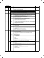
[ 1 ] GENERAL DESCRIPTION . . . . . . . . . . . . . . . . . . . . . . . . . . . . . . . . . . . . . . . . . . 1-1
[ 2 ] PRODUCT SPECIFICATIONS . . . . . . . . . . . . . . . . . . . . . . . . . . . . . . . . . . . . . . . 2-1
[ 3 ] EXTERNAL VIEW AND INTERNAL STRUCTURE . . . . . . . . . . . . . . . . . . . . . . . 3-1
[ 4 ] UNPACKING AND INSTALLATION . . . . . . . . . . . . . . . . . . . . . . . . . . . . . . . . . . 4-1
[ 5 ] GENERAL DESCRIPTIONS OF EACH SECTION . . . . . . . . . . . . . . . . . . . . . . . 5-1
[ 6 ] DISASSEMBLY AND ASSEMBLY
. . . . . . . . . . . . . . . . . . . . . . . . . . . . . . . . . . . 6-1
[ 7 ] ADJUSTMENTS . . . . . . . . . . . . . . . . . . . . . . . . . . . . . . . . . . . . . . . . . . . . . . . . . . 7-1
[ 8 ] SIMULATIONS . . . . . . . . . . . . . . . . . . . . . . . . . . . . . . . . . . . . . . . . . . . . . . . . . . . 8-1
[ 9 ] SELF DIAGNOSTICS . . . . . . . . . . . . . . . . . . . . . . . . . . . . . . . . . . . . . . . . . . . . . 9-1
[10] SERVICE AT MEMORY TROUBLE AND
[10] MAIN CONTROL PWB REPLACEMENT . . . . . . . . . . . . . . . . . . . . . . . . . . . . . 10-1
[11] MAINTENANCE . . . . . . . . . . . . . . . . . . . . . . . . . . . . . . . . . . . . . . . . . . . . . . . . . 11-1
[12] ELECTRICAL SECTION . . . . . . . . . . . . . . . . . . . . . . . . . . . . . . . . . . . . . . . . . . 12-1
Parts marked with "!" is important for maintaining the safety of the set. Be sure to replace these parts with specified
ones for maintaining the safety and performance of the set.
SHARP CORPORATION
This document has been published to be used
for after sales service only.
The contents are subject to change without notice.
CONTENTS
[ 1 ] GENERAL DESCRIPTION
...................
1. Features . . . . . . . . . . . . . . . . . . . . . . . . . . . . . . . . . . . .
2. Target users . . . . . . . . . . . . . . . . . . . . . . . . . . . . . . . . .
3. System outline . . . . . . . . . . . . . . . . . . . . . . . . . . . . . . . .
[ 2 ] PRODUCT SPECIFICATIONS
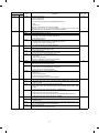
(4) Lens (Fixed focus lens) . . . . . . . . . . . . . . . . .5-3
(5) Lens home position sensor (LHPS) . . . . . . . .5-3
(6) Lens base . . . . . . . . . . . . . . . . . . . . . . . . . . . .5-3
(7) Lens drive shaft . . . . . . . . . . . . . . . . . . . . . . .5-4
(8) Lens drive wire . . . . . . . . . . . . . . . . . . . . . . . .5-4
(9) No. 4/5 mirror base . . . . . . . . . . . . . . . . . . . .5-4
(10) Mirror motor . . . . . . . . . . . . . . . . . . . . . . . . . .5-4
(11) Mirror home position sensor (MHPS) . . . . . . .5-4
(12) No. 2/3 mirror base . . . . . . . . . . . . . . . . . . . .5-4
(13) Copy lamp unit . . . . . . . . . . . . . . . . . . . . . . .5-4
(14) Thermal fuse . . . . . . . . . . . . . . . . . . . . . . . . .5-4
(15) Reflector . . . . . . . . . . . . . . . . . . . . . . . . . . . . .5-4
(16) Exposure adjustment plates . . . . . . . . . . . . . .5-4
(17) Mirror base drive wire . . . . . . . . . . . . . . . . . . .5-4
(18) Lens drive motor . . . . . . . . . . . . . . . . . . . . . .5-4
(19) AE sensor . . . . . . . . . . . . . . . . . . . . . . . . . . . .5-4
5-2. Basic operations . . . . . . . . . . . . . . . . . . . . . . . . . . .5-4
6. Copy process . . . . . . . . . . . . . . . . . . . . . . . . . . . . . . . . .5-6
(1) Photoconductor . . . . . . . . . . . . . . . . . . . . . . . . . . .5-6
(2) Process diagram . . . . . . . . . . . . . . . . . . . . . . . . . . .5-6
(3) Actual process . . . . . . . . . . . . . . . . . . . . . . . . . . . .5-7
(4) Transit of photoconductor drum surface
potential . . . . . . . . . . . . . . . . . . . . . . . . . . . . . . . .5-11
(5) Process correction system . . . . . . . . . . . . . . . . . .5-12
1) Outline of the correction system . . . . . . . . . . .5-12
2) Correction operation . . . . . . . . . . . . . . . . . . . .5-12
1-1
1-1
1-1
1-1
. . . . . . . . . . . . . . . 2-1
1. Basic specifications . . . . . . . . . . . . . . . . . . . . . . . . . . . 2-1
2. Details of each section . . . . . . . . . . . . . . . . . . . . . . . . . 2-1
3. Supplies . . . . . . . . . . . . . . . . . . . . . . . . . . . . . . . . . . . . 2-3
[ 3 ] EXTERNAL VIEW AND INTERNAL
STRUCTURE . . . . . . . . . . . . . . . . . . . . . . . . . . . . . . .
1.
2.
3.
4.
5.
6.
7.
External view and internal structure . . . . . . . . . . . . . . .
Operation panel . . . . . . . . . . . . . . . . . . . . . . . . . . . . . . .
Cross section . . . . . . . . . . . . . . . . . . . . . . . . . . . . . . . .
Switches, sensors, detectors . . . . . . . . . . . . . . . . . . . .
Clutches, solenoids . . . . . . . . . . . . . . . . . . . . . . . . . . .
Motors . . . . . . . . . . . . . . . . . . . . . . . . . . . . . . . . . . . . . .
PWBs . . . . . . . . . . . . . . . . . . . . . . . . . . . . . . . . . . . . . .
[ 4 ] UNPACKING AND INSTALLATION
. . . . . . . . . 4-1
1. Packing drawing . . . . . . . . . . . . . . . . . . . . . . . . . . . . . .
2. Installation . . . . . . . . . . . . . . . . . . . . . . . . . . . . . . . . . .
(1) Environment . . . . . . . . . . . . . . . . . . . . . . . . . . . . . . .
(2) Space around the machine . . . . . . . . . . . . . . . . . . .
(3) Installing table . . . . . . . . . . . . . . . . . . . . . . . . . . . . .
(4) Power source . . . . . . . . . . . . . . . . . . . . . . . . . . . . . .
(5) Grounding . . . . . . . . . . . . . . . . . . . . . . . . . . . . . . . .
3. Installation procedure . . . . . . . . . . . . . . . . . . . . . . . . . .
(1) Optical system unlocking . . . . . . . . . . . . . . . . . . . . .
(2) Cassette setting . . . . . . . . . . . . . . . . . . . . . . . . . . . .
(3) Developer setting . . . . . . . . . . . . . . . . . . . . . . . . . . .
(4) Toner supply . . . . . . . . . . . . . . . . . . . . . . . . . . . . . .
(5) Toner density sensor level check . . . . . . . . . . . . . .
(6) Accessory attachment . . . . . . . . . . . . . . . . . . . . . . .
4. Locking procedure for transit or repacking . . . . . . . . . .
(1) No.2/No.3 mirror unit (Mirror base B) lock . . . . . . .
(2) No.4/no.5 mirror unit (Mirror base C) lock . . . . . . .
5. Optional multi bypass feeder unit Installation Manual . .
(1) Open the upper unit of the main copier unit. . . . . . .
(2) Release the lock for the manual bypass unit and
remove the manual bypass unit. . . . . . . . . . . . . . . .
(3) Mount the multi bypass feeder unit onto
the main copier unit. . . . . . . . . . . . . . . . . . . . . . . . .
[ 5 ] GENERAL DESCRIPTIONS OF
EACH SECTION . . . . . . . . . . . . . . . . . . . . . . . . . . . .
1.
2.
3.
4.
3-1
3-1
3-2
3-3
3-4
3-5
3-6
3-7
Paper feed section . . . . . . . . . . . . . . . . . . . . . . . . . . . .
Separation, transport section . . . . . . . . . . . . . . . . . . . .
Fuser, paper exit section . . . . . . . . . . . . . . . . . . . . . . .
Developer section . . . . . . . . . . . . . . . . . . . . . . . . . . . .
4-1. General descriptions . . . . . . . . . . . . . . . . . . . . . . .
(1) Two-component developer . . . . . . . . . . . . . .
(2) Two-component magnetic brush
development . . . . . . . . . . . . . . . . . . . . . . . . .
(3) Developing bias . . . . . . . . . . . . . . . . . . . . . .
5. Optical system . . . . . . . . . . . . . . . . . . . . . . . . . . . . . . . .
5-1. General descriptions . . . . . . . . . . . . . . . . . . . . . . .
(1) Original table . . . . . . . . . . . . . . . . . . . . . . . .
(2) Copy lamp . . . . . . . . . . . . . . . . . . . . . . . . . .
(3) Mirror . . . . . . . . . . . . . . . . . . . . . . . . . . . . . .
4-1
4-1
4-1
4-2
4-2
4-2
4-2
4-3
4-3
4-3
4-4
4-5
4-5
4-5
4-6
4-6
4-6
4-6
4-6
[ 6 ] DISASSEMBLY AND ASSEMBLY
. . . . . . . . . . . 6-1
1. Paper feed section, paper transport section,
power section . . . . . . . . . . . . . . . . . . . . . . . . . . . . . . . . .6-1
1-1. Paper feed unit . . . . . . . . . . . . . . . . . . . . . . . . . . .6-1
1-2. Paper feed roller ass’y removal . . . . . . . . . . . . . .6-1
1-3. Separation roller . . . . . . . . . . . . . . . . . . . . . . . . .6-2
1-4. Takeup roller, paper feed roller . . . . . . . . . . . . . .6-2
1-5. Resist roller . . . . . . . . . . . . . . . . . . . . . . . . . . . . . .6-3
1-6. Transport belt . . . . . . . . . . . . . . . . . . . . . . . . . . . .6-4
1-7. Socket holder unit . . . . . . . . . . . . . . . . . . . . . . . . .6-4
1-8. Lower unit PWB . . . . . . . . . . . . . . . . . . . . . . . . . .6-4
1-9. Cassette paper empty detector (CPED1) . . . . . . .6-4
1-10. Power unit . . . . . . . . . . . . . . . . . . . . . . . . . . . . . . .6-4
2. Manual paper feed section . . . . . . . . . . . . . . . . . . . . . . .6-5
2-1. Manual paper feed roller, manual takeup roller . . .6-5
2-2. Reverse rotation roller ass’y . . . . . . . . . . . . . . . . . .6-5
3. Fuser section . . . . . . . . . . . . . . . . . . . . . . . . . . . . . . . . .6-6
3-1. Fuser unit removal . . . . . . . . . . . . . . . . . . . . . . . . .6-6
3-2. Heater lamp replacement . . . . . . . . . . . . . . . . . . . .6-6
3-3. Upper heat roller ass’y removal . . . . . . . . . . . . . . .6-7
3-4. Upper separation pawl replacement . . . . . . . . . . . .6-7
3-5. Lower cleaning roller and
lower heat roller replacement . . . . . . . . . . . . . . . . .6-7
3-6. Scraper replacement . . . . . . . . . . . . . . . . . . . . . . .6-8
3-7. Thermistor/thermostat removal . . . . . . . . . . . . . . . .6-8
4. Optical system . . . . . . . . . . . . . . . . . . . . . . . . . . . . . . . .6-9
4-1. Copy lamp replacement . . . . . . . . . . . . . . . . . . . . .6-9
4-2. Copy lamp unit replacement . . . . . . . . . . . . . . . . . .6-9
4-3. Mirror base drive wire replacement . . . . . . . . . . . .6-9
4-4. Lens and lens drive wire replacement . . . . . . . . .6-10
4-5. No. 4/5 mirror unit and
peripheral parts replacement . . . . . . . . . . . . . . . .6-11
4-6
4-7
5-1
5-1
5-2
5-2
5-2
5-2
5-2
5-2
5-2
5-3
5-3
5-3
5-3
5-3
I
5.
6.
7.
8.
4-6. Optical unit removal . . . . . . . . . . . . . . . . . . . . . .
4-7. Other parts in the optical system . . . . . . . . . . . . .
4-8. Light adjustment plate/temperature fuse
removal . . . . . . . . . . . . . . . . . . . . . . . . . . . . . . .
Drum section . . . . . . . . . . . . . . . . . . . . . . . . . . . . . . .
5-1. Drum unit removal . . . . . . . . . . . . . . . . . . . . . . . .
Developer section . . . . . . . . . . . . . . . . . . . . . . . . . . .
6-1. Developer unit removal . . . . . . . . . . . . . . . . . . . .
6-2. Developer cartridge removal . . . . . . . . . . . . . . .
6-3. Toner motor removal . . . . . . . . . . . . . . . . . . . . .
6-4. Toner density sensor . . . . . . . . . . . . . . . . . . . . .
Operation panel section/medium cabinet . . . . . . . . . .
Major parts in the frame side . . . . . . . . . . . . . . . . . . . .
8-1. Ozone filter . . . . . . . . . . . . . . . . . . . . . . . . . . . . .
8-2. Optical unit cooling fan removal . . . . . . . . . . . . .
8-3. Ventilation fan motor . . . . . . . . . . . . . . . . . . . . .
8-4. Transport roller clutch . . . . . . . . . . . . . . . . . . . .
8-5. Paper exit sensor . . . . . . . . . . . . . . . . . . . . . . . .
6. User simulations . . . . . . . . . . . . . . . . . . . . . . . . . . . . . .8-12
6-11
6-11
[ 9 ] SELF DIAG
1.
2.
3.
4.
5.
6-12
6-13
6-13
6-13
6-13
6-13
6-13
6-14
6-14
6-14
6-14
6-14
6-15
6-15
6-15
[10] SERVICING AT MEMORY TROUBLE AND
MAIN CONTROL PWB REPLACEMENT . . . .10-1
1.
2.
3.
4.
5.
..............................
Outline . . . . . . . . . . . . . . . . . . . . . . . . . . . . . . . . . . . . . .
Purpose . . . . . . . . . . . . . . . . . . . . . . . . . . . . . . . . . . . . .
Operating procedure . . . . . . . . . . . . . . . . . . . . . . . . . . .
Purpose list . . . . . . . . . . . . . . . . . . . . . . . . . . . . . . . . . .
Details of simulations . . . . . . . . . . . . . . . . . . . . . . . . . .
. . . . . . . . . . . . . . . . . . . . . . . . . . . . .11-1
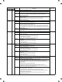
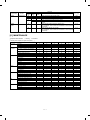
[12] ELECTRICAL SECTION
. . . . . . . . . . . . . . . . . . . .12-1
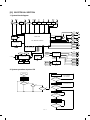
1. System block diagram . . . . . . . . . . . . . . . . . . . . . . . . . .12-1
2. System operation at power ON . . . . . . . . . . . . . . . . . . .12-1
3. Main circuit . . . . . . . . . . . . . . . . . . . . . . . . . . . . . . . . . .12-2
(1) Block diagram . . . . . . . . . . . . . . . . . . . . . . . . . . . .12-2
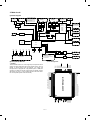
(2) CPU (IC110) M37702 . . . . . . . . . . . . . . . . . . . . . .12-2
1 Outline . . . . . . . . . . . . . . . . . . . . . . . . . . . . . . .12-2
2 Pin arrangement . . . . . . . . . . . . . . . . . . . . . . .12-2
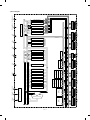
3 Block diagram . . . . . . . . . . . . . . . . . . . . . . . . .12-3
4 CPU: M37702 (IC110) pin signals . . . . . . . . . .12-4
(3) Start/stop control circuit . . . . . . . . . . . . . . . . . . . .12-5
(4) Heater lamp control circuit . . . . . . . . . . . . . . . . . .12-6
1 General . . . . . . . . . . . . . . . . . . . . . . . . . . . . . .12-6
(5) Driver circuit (Solenoid, magnetic clutch) . . . . . . .12-7
1 General . . . . . . . . . . . . . . . . . . . . . . . . . . . . . .12-7
2 Operation . . . . . . . . . . . . . . . . . . . . . . . . . . . .12-7
(6) Stepping motor drive circuit . . . . . . . . . . . . . . . . .12-7
1 General . . . . . . . . . . . . . . . . . . . . . . . . . . . . . .12-7
(7) AE (Auto Exposure) sensor circuit . . . . . . . . . . . .12-7
(8) Toner supply motor drive circuit . . . . . . . . . . . . . .12-8
(9) Reset IC (IC113) . . . . . . . . . . . . . . . . . . . . . . . . . .12-8
1 Outline . . . . . . . . . . . . . . . . . . . . . . . . . . . . . . .12-8
2 Operation . . . . . . . . . . . . . . . . . . . . . . . . . . . .12-8
(10) Copy lamp control section . . . . . . . . . . . . . . . . . .12-9
4. Operating section . . . . . . . . . . . . . . . . . . . . . . . . . . . .12-11
(1) Outline . . . . . . . . . . . . . . . . . . . . . . . . . . . . . . . .12-11
(2) Display circuit . . . . . . . . . . . . . . . . . . . . . . . . . . .12-12
1 Block diagram . . . . . . . . . . . . . . . . . . . . . . . .12-12
2 Operation . . . . . . . . . . . . . . . . . . . . . . . . . . .12-12
(3) LED display . . . . . . . . . . . . . . . . . . . . . . . . . . . .12-13
5. Power section . . . . . . . . . . . . . . . . . . . . . . . . . . . . . .12-13
(1) Signal name and output voltage . . . . . . . . . . . . .12-13
. . . . . . . . . . . . . . . . . . . . . . . . . . . . . 7-1
1. Developer section . . . . . . . . . . . . . . . . . . . . . . . . . . . . 7-1
(1) MG roller main pole position adjustment . . . . . . . . . 7-1
(2) Adjustment of clearance between DV doctor and
MG roller . . . . . . . . . . . . . . . . . . . . . . . . . . . . . . . . . 7-2
2. Optical section . . . . . . . . . . . . . . . . . . . . . . . . . . . . . . . . 7-3
A. Adjustments list . . . . . . . . . . . . . . . . . . . . . . . . . . . . 7-3
B. Notes . . . . . . . . . . . . . . . . . . . . . . . . . . . . . . . . . . . . 7-3
C. Adjustment contents . . . . . . . . . . . . . . . . . . . . . . . . 7-6
(1) Lens . . . . . . . . . . . . . . . . . . . . . . . . . . . . . . . . . . 7-6
(2) Mirror . . . . . . . . . . . . . . . . . . . . . . . . . . . . . . . . 7-7
(3) Image distortion adjustment . . . . . . . . . . . . . . . 7-8
(4) Copy image center position adjustment . . . . . 7-12
(5) Focus adjustment (Resolution adjustment) . . . 7-14
(6) Copy magnification ratio adjustment . . . . . . . . 7-15
(7) Uniformity adjustment . . . . . . . . . . . . . . . . . . . 7-18
(8) Image loss/void area adjustment . . . . . . . . . . . 7-18
3. COPY DENSITY ADJUSTMENT . . . . . . . . . . . . . . . . 7-23
(1) Copy density adjustment timing . . . . . . . . . . . . . 7-23
(2) Note for copy density adjustment . . . . . . . . . . . . 7-23
(3) Necessary items for the copy density adjustment 7-23
(4) Copy density adjustment mode . . . . . . . . . . . . . . 7-23
(5) Copy density adjustment procedure . . . . . . . . . . 7-23
A. Test chart (UK0G-0162FCZZ) setting . . . . . . 7-23
B. Normal copy mode (Non-toner-save mode)
copy density adjustment . . . . . . . . . . . . . . . . 7-23
C. Normal copy mode (Toner save mode)
copy density adjustment . . . . . . . . . . . . . . . . 7-24
D. Photo copy mode (Non-toner-save mode)
copy density adjustment . . . . . . . . . . . . . . . . 7-24
E. Auto copy mode (Non-toner-save mode)
copy density adjustment . . . . . . . . . . . . . . . . 7-24
F. Auto copy mode (Toner save mode) copy
density adjustment . . . . . . . . . . . . . . . . . . . . . 7-25
(6) Copy density adjustment table . . . . . . . . . . . . . . 7-26
4. Others . . . . . . . . . . . . . . . . . . . . . . . . . . . . . . . . . . . . . 7-27
(1) Transfer charger wire installation . . . . . . . . . . . . 7-27
(2) How to adjust the separation corona valtage . . . 7-27
(3) How to adjust the developing bias voltage . . . . . 7-27
1.
2.
3.
4.
5.
General . . . . . . . . . . . . . . . . . . . . . . . . . . . . . . . . . . . . .10-1
Purpose . . . . . . . . . . . . . . . . . . . . . . . . . . . . . . . . . . . .10-1
Remedies . . . . . . . . . . . . . . . . . . . . . . . . . . . . . . . . . . .10-1
Set value recording sheet . . . . . . . . . . . . . . . . . . . . . . .10-4
Memory simulation list . . . . . . . . . . . . . . . . . . . . . . . . .10-5
[11] MAINTENANCE
[ 7 ] ADJUSTMENTS
[ 8 ] SIMULATIONS
. . . . . . . . . . . . . . . . . . . . . . . . . . . . . . . . . .9-1
Summary/purpose . . . . . . . . . . . . . . . . . . . . . . . . . . . . .9-1
Operation . . . . . . . . . . . . . . . . . . . . . . . . . . . . . . . . . . . .9-1
Clearing the self diag display . . . . . . . . . . . . . . . . . . . . .9-1
Self diag contents . . . . . . . . . . . . . . . . . . . . . . . . . . . . . .9-2
Conditions for the JAM display . . . . . . . . . . . . . . . . . . . .9-7
8-1
8-1
8-1
8-1
8-2
8-3
II
[1] GENERAL DESCRIPTION
1. Features
[Small]
• Compact design
• Small area for operation
[Speedy]
• Warm-up time 30 sec or less, the first copy 5.9 sec ∼ the fastest in
the class.
[Soft]
• The energy save mode reduces the total power consumption.
• Ozone generation is limited.
• Use of materials which can be recycled.
User simulation
The user can select the desired operating conditions easily. Auto
clear time, power save mode time, power save mode warm up time
can be set by the user simulation.
2. Target users
Average copy volume of 2,000 ∼ 3,000 sheets/month (max. 15,000
sheets/month)
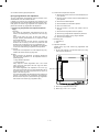
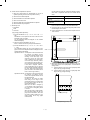
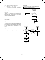
3. System outline
Zooming range
(64 ~ 129%)
Single manual feed (Standard)
50
250-sheet tray
50-sheet multi manual feed unit (SF-MF14)
(Option)
1–1
(10) Void width
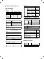
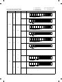
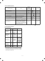
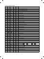
[2] PRODUCT SPECIFICATIONS
1. Basic specifications
Void area
(1)
Type:
Table top
(2)
Copy speed
Paper size
Normal
Enlargement
Reduction
B4
11 sheets/min
10 sheets/min
12 sheets/min
A4 (Landscape)
14 sheets/min
10 sheets/min
12 sheets/min
B5 (Landscape)
14 sheets/min
10 sheets/min
12 sheets/min
10″ × 14″
11 sheets/min
10 sheets/min
12 sheets/min
Legal
11 sheets/min
10 sheets/min
12 sheets/min
Letter
(Landscape)
14 sheets/min
10 sheets/min
12 sheets/min
(4)
Reduction
Enlargement
Lead edge
3.0mm or less
Lead edge
3.0mm or less
Side (front)
3.0mm or less
Side (front)
3.0mm or less
Side (front)
3.0mm or less
Rear edge
1mm ∼ 3.0mm
Rear edge
1mm ∼ 3.0mm
Rear edge
1mm ∼ 3.0mm
Lead edge
3.0mm max.
Lead edge
5.0mm max.
Lead edge
2.5mm max.
Side (front)
3.0mm max.
Side (front)
5.0mm max.
Side (front)
2.5mm max.
Rear edge
4.0mm max.
Rear edge
6.0mm max.
Rear edge
3.0mm max.
Image
loss
(11) Paper exit
Paper exit tray capacity
Note: Copy speeds in the enlargement/reduction copy are the
same in all the rates.
(3)
Normal
Lead edge
3.0mm or less
(12) External view
Warm-up time
Normal
30 sec or less (20 °C, 65%RH, rated
voltage)
(Preheat YES/NO)
10sec or less (Preheat mode)
Max. 30sec (auto power shut off mode)
Jam recovery time
8sec (Conditions: Standard condition
after 60sec of leaving after opening
the door.)
W × D × H (mm) OC top
500 × 492 × 288
Occupying area
500 + 257 (paper exit tray) +
205 (option Multi paper feed
unit)
W (mm)
D (mm)
Weight
492
About 27.4 kg
(13) Power source
First copy time
First copy time from
each paper feed port
100 sheets
Tray: 5.9sec
Manual: 5.9sec
Voltage
100V, 110V, 120V, 127V, 220V, 220 ∼ 230V,
230 ∼ 240V, 240V
Frequency
50/60Hz common
(14) Power consumption
(5)
(6)
Jam recovery time: 5 sec (Condition: Jam in a section except
for the fuser section, within 6.0 sec from
door open, standard condition.)
Multi copy
Max. quantity of multi copy
(7)
99 sheets
Original
Max. power consumption
1.4 kW
Average power consumption when operating
(Ref. value)
582.4 Wh
Power consumption in standby (Ref. value)
72.5 Wh
Power consumption in pre-heating (Ref. value)
47.7 Wh
Power consumption in auto power shut off
(Ref. value)
14.8 Wh
Max. original size
B4/10″ × 14″
Original reference
position
Left side, about 12mm from the rear
Auto OFF mode (Ref. value)
Dry heater connected
Dry heater not connected
9.5 Wh
0 Wh
Detection
NO
Energy consumption efficiency
49.4 Wh
Detection size
AB series
Note: Max. value when an option is installed.
Inch series
(8)
Copy magnification ratio
Fixed
ratio
AB series
Inch series
Zoom width
(9)
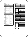
2. Details of each section
3R+3E/129, 122, 115, 81, 70, 64%
(1)
2R+2E/129, 117, 78, 64%
64 ∼ 129%
Paper feed
Copying size
(Max. ∼ Min.)
Exposure
Exposure mode
Auto/Manual/Photo
Manual steps
9 steps
2–1
AB series
B4 ∼ A6 (Postcard)
Inch series
10 × 14 ∼ 5 1/2 × 8 1/2
Paper feed system
1 tray + single manual feed
Paper feed capacity
250 sheets × 1
•
AB series
Each paper
feed port
Tray
(2)
Paper feed
size
Paper
weight
B4 ∼ A5
56 ∼
(Landscape) 80g/m2
Single
B4 ∼ A6
manual feed postcard
(Portrait)
52 ∼
130g/m2
* For paper of 104 ∼
130g/m2, A4 or smaller.
Optical section
Paper
feed
position
Light source
Halogen lamp
Exposure system
Slit exposure by moving the
light source
Recommended Front
recycle paper
Magnification ratio changing
system
By changing the lens
position and scan speed.
No. 2 original,
OPH, label,
recommended
recycle paper,
postcards
Lens
Fixed focus lens
Special paper
Side
(3)
Process section
Multi
manual
feed (OP)
•
•
•
B4 ∼ A5
56 ∼
(Landscape) 80g/m2
When in
single
paper
feed
B4 ∼ A6
52 ∼
130g/m2
* For paper of 104 ∼
2
130g/m , A4 or smaller.
Recommended Side
recycle paper
Recommended Side
recycle paper,
No. 2 original,
OPH label
Paper feed
size
10 × 14 ∼
5 1/2 × 8
1/2
Paper
weight
15 ∼ 21 lbs.
14 ∼ 34.5
lbs.
* For paper of 28 ∼
Special paper
Side
•
34.5lbs, letter size or
smaller.
Multi
manual
feed (OP)
•
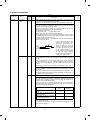
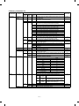
Copy mode
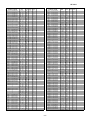
Simulations
No.
Grid
voltage
Standard
8-02
–750V
Photo
8-03
–460V
Toner save
8-04
–634V
•
Side
–50.0µA ± 4µA
Developer section
Paper
feed
position
Recommended Front
recycle paper
No. 2 original,
OHP.
recommended
recycle paper
Discharge plate/separation pawl
Charge/Transfer
charger applied
voltage
(4)
Single
10 × 14 ∼
manual feed 5 1/2 × 8
1/2
•
(–) DC scorotron system
Main charger
grid voltage
Inch series
Tray
(–) DC scorotron system
Transfer system
Separation
system
When in
multi
paper
feed
Each paper
feed port
Charging system
Developing system
Two-component developing
system
Toner density detection
system
Magnetic sensor system
Toner box capacity
Toner 210 ±5g
Developing bias
DC–200V±3V
Developer
Material
Iron powder carrier
Charging system
Negatively charged by friction
Toner
Charging system
When in
multi
paper
feed
10 × 14 ∼
5 1/2 × 8
1/2
When in
single
paper
feed
10 × 14 ∼
5 1/2 × 8
1/2
15 ∼ 21 lbs.
Recommended
recycle paper
(5)
Positively charged by friction
Fuser section
Fusing system
14 ∼ 34.5
lbs.
* For paper of 28 ∼
No. 2 original,
OHP, label,
recommended
recycle paper
Side
180°C
Heater lamp
100V
Halogen lamp 1000 W × 1 pc.
110V
Halogen lamp 1000 W × 1 pc.
120V
Halogen lamp 1000 W × 1 pc.
127V
Halogen lamp 1000 W × 1 pc.
220V
Halogen lamp 1000 W × 1 pc.
230V
Halogen lamp 1000 W × 1 pc.
240V
Halogen lamp 1000 W × 1 pc.
34.5lbs, letter size or
smaller.
(6)
Drive section
Main motor
standard
2–2
Heat roller system
Upper heat roller surface
temperature
3-phase full wave drive, DC brushless
Rating: DC32V, max. 1.32A, 1500 rpm
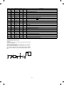
3. Supplies
Middle and South America
No.
Name
1
OPC drum kit
2
Black developer
3
Black toner
4
Heat roller kit
Content
OPC drum
Cleaning blade
Black developer (560g)
x 1
x 1
x 10
Black toner cartridge (200g)
x 10
Upper heat roller
Upper fusing separation pawl
Fusing bearing (F)
Fusing bearing (R)
Roller stopper
Lower heat roller
Lower fusing separation pawl
x
x
x
x
x
x
x
1
3
1
1
2
1
4
Product name
Life
SF114DR
50K
SF114LD
(SF114DVx10)
SF114LT
(SF114Tx10)
60K × 10
6K × 10
SF214HR
(For LAG: SF214HR1)
80K
Note 1: The heat roller kit for this series is common with the previous
models SF-2314/2414/2514.
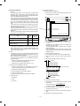
4 Supply storing condition
Environmental conditions
Observe the following environmental conditions to ensure the copy
quality and machine performance.
(%)RH
1 Standard condition
20 ∼ 25 °C, 65 ±5% RH
90
2 Operational condition
(%)RH
85
10
60
40
-5
(˚C)
Storage period:
OPC drum
Max. 36 months from production
Developer/Toner
Max. 24 months from production
20
10
30 35
(˚C)
5 Identification of production number
A. OPC drum
3 Shipping condition of copier (within 2 weeks)
The lot no. is of 10 digits. Each digit indicates as follows. This number
is printed on the F side flange.
(%)RH
1
90
60
2
3
4
5
6
7
8
9
1 Numeral
Indicates the OPC drum sensitivity.
2 Alphabet
Indicates the model code. "M" is the code for this model.
20
3 Numeral
The end digit of the year of coating.
-20
30 45
(˚C)
4 Numeral or X, Y, Z
Indicates the month of coating.
X means October, Y November, and Z December.
5 6 Numeral
Indicates the day of coating.
7 Numeral or X, Y, Z
Indicates the month of packing.
X means October, Y November, and Z December.
8 9 Numeral
Indicates the day of packing.
2–3
10
F Alphabet
Indicates the factory of production. "A" is the code for Nara plant.
B. Developer and toner
The lot number of toner is put on the individual cartridge package and
on the group package, and that of toner is put on the bag and the
group package.
The lot number is of 7 digits, each digit indicating as follows:
1
2
3
4
5
6
7
1 Alphabet
Indicates the factory of production.
2 Numeral
Indicates the end digit of the year of production.
3 4 Numeral
Indicates the month of production.
5 6 Numeral
Indicates the day of production.
7 Numeral
Indicates the sub lot number.
Normal
C
A
B
1
2
3
4
When a change is made on the product in the same operation system:
Normal
1
C
5
2
A
6
3
B
7
4
8
A,B,C: Operation system
2–4
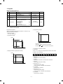
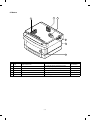
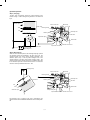
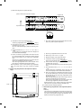
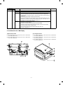
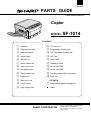
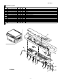
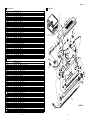
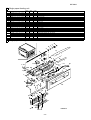
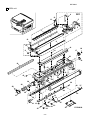
[3] EXTERNAL VIEW AND INTERNAL STRUCTURE
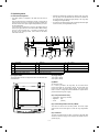
1. External view and internal structure
1
2
4
3
5
9
8
7
6
Upper unit
Lower unit
10
No.
1
4
7
F
I
Name
No.
Photoconductive drum
2
5
8
G
J
Exit tray
Operation panel
Power switch
Fusing unit lever
11
13
12
Name
Document cover
Manual bypass
Front cover
Toner cartridge
Release lever
3–1
14
No.
3
6
9
H
Name
Document glass
Manual bypass guide
Paper tray
Fusing unit
2. Operation panel
SF-1014
1
2
3
5
6
7
129%
117%
100%
78%
64%
AUTO
1 2 3 4 5
4
No.
Name
8
9
10
51/2x81/2 81/2x11 ZOOM
81/2x11 10x14
11
12
13
14
C
%
81/2x14 81/2x11
81/2x11 51/2x81/2
1
2
3
4
6
7
8
9
15
5
0
16
No.
Name
No
17
Name
1
Auto/manual/photo key and indicators
2
Light and dark keys and exposure
indicators
4
Developer replacement required
indicator
5
Misfeed indicator
6
Toner required indicator
7
F
I
L
Copy ratio selector key and indicators
8
G
J
M
Zoom keys
9
H
K
ZOOM indicator
Copy quantity display
Clear key
Zero/readout key
Copy ratio display key
Power save indicator
Print button and READY indicator
3–2
3
Maintenance required indicator
10-key pad
Tray select key and indicators
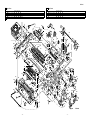
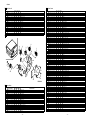
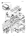
3. Cross section
3
4
5
6
7
8
9
10 11
12
2
13
14
15
16
1
17
18
34
19
20
21
22
23
33 32
No.
1
4
7
F
I
L
O
R
U
X
[
^
Name
No.3 mirror
Cleaner unit
No.1 mirror
No.6 mirror
No.4 mirror
Manual paper feed roller
Tray paper feed takeup roller
Tray paper feed roller
Resist roller
Suction belt
Lower heat roller
31 30 29 28 27 26
No.
2
5
8
G
J
M
P
S
V
Y
\
Name
No.2 mirror
Discharge lamp
Copy lamp
Blank lamp
No.5 mirror
Manual feed take-up roller
Tray transport follower roller
Option tray transport roller
Transfer charger
Upper heat roller
Lower separation pawl
Heater lamp
3–3
25 24
No
3
6
9
H
K
N
Q
T
W
Z
]
Name
Drum separation pawl
Main charger unit
Lens unit
Developer magnet roller
Developer tank
Manual paper feed follower roller
Transport roller (Upper)
Resist roller
Photoconductor drum
Lower cleaning roller
Upper separation pawl
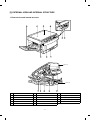
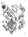
4. Switches, sensors, detectors
3
2
5
1
4
7
6
No.
Abbreviation
Function
Type
Operation
1
2
3
4
5
6
POD
Paper out sensor
Transmission photo sensor
H when paper is sensed.
MHPS
Mirror home position sensor
Transmission photo sensor
H at the home position.
LHPD
Lens home position sensor
Transmission photo sensor
H at the home position.
PWD
Paper size (large/small) sensor
Transmission photo sensor
L with the large size.
PPD
Paper transport sensor
Transmission photo sensor
L when paper is sensed.
CPED1
Tray paper empty sensor
Transmission photo sensor
H when paper is present.
7
PID (MFD1)
Paper sensor for Manual paper feed unit
(only single Manual Paper feed unit)
Transmission photo sensor
L when the cover is open.
3–4
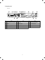
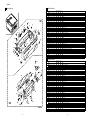
5. Clutches, solenoids
1
2
6
3
5
4
No.
1
2
3
4
5
6
Abbreviation
Name
Function and operation
PSPS
Paper separation solenoid
For paper separation solenoid drive
RRC
Resist roller clutch
For resist roller rotation
TRC
Transport roller clutch
For transport roller rotation
MPFS
Manual paper feed solenoid
For takeup roller pressing
CPFC1
Tray paper feed clutch
For paper feed roller rotation
MPFC
Multi paper feed clutch
For multi paper feed roller rotation
3–5
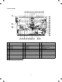
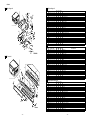
6. Motors
2
1
3
5
4
6
No.
Abbreviation
Name
Function
Type
For ventilation of the fuser unit.
For cooling the machine and removing ozone.
DC brushless
1
VFM
Paper exit fan motor
2
3
4
5
6
CFM
Cooling fan motor
For cooling the optical system
DC brushless
MM
Main motor
For the main body drive and the option drive
DC brushless
LM
Lens motor
For the optical lens drive
DC stepping
MRM
Mirror motor
For the optical mirror base drive
DC brushless
TM
Toner motor
For toner supply
DC synchronous
3–6
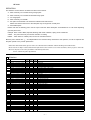
7. PWBs
8
2
1
3
4
5
6
7
No.
1
2
3
4
5
6
7
8
Name
AC circuit PWB
Description
AC power input
Discharge lamp PWB
Discharge lamp drive
Main PWB
Main body control
AE PWB
Document density auto exposure detection
Blank lamp PWB
Blank lamp control
Lower unit PWB
Lower unit parts control
High voltage PWB
Supply of the process high voltage and the developer bias voltage.
Operation PWB
Operation input, display control
3–7
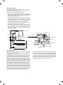
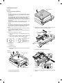
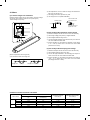
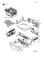
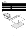
2. Installation
[4] UNPACKING AND INSTALLATION
Installation conditions
The following installing conditions must be satisfied to assure the
normal operations of the machine.
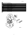
1. Packing drawing
(1) Environment
1 Keep the machine away from direct sunlight and avoid installation near a window or in a bright place.
(Draw the curtain and close the blind shutter completely.)
The plastic parts and the original cover may be deformed by direct
sunlight. Avoid installation near a window even with frosted glass.
2 Avoid installation in high temperature or high humitity environments. Also, avoid installation where temperature or
humidity may change quickly. (e.g., near an air conditioner).
Otherwise copy papers may be dampened and condensation may
be generated in the machine. This may result in paper jams or
poor copy quality.
(Ideal conditions):
(Temperature/humidity range): 15°C ∼ 30°C (59°F ∼ 86°F),
20% ∼ 85%
65% for 35°C (95°F)
List of packing materials and accessories
Name
The best suitable conditions for machine
operation:
20°C ∼ 25°C: 65 ±5%RH
Q’ty
1
Packing case
1
2
Body
1
% RH
3
Polyethylene bag for paper exit tray
1
85
4
Vinyl sheet for body
1
65
5
Bottom case
1
Humidity
6
Bottom case pad (L)
1
7
Bottom case pad (R)
1
8
AC cord sleeve
1
9
Paper exit tray
1
10
Instruction Manual
1
20
15
(59˚)
4–1
30 35 ˚ C (˚F)
(86˚) (95˚)
3 Avoid installation where there is a lot of dust or vibrations.
If dust enters the machine, it may degrade copy quality and cause
malfunctions.
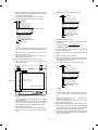
(2) Space around the machine
Allow a space of about 15 cm (6 inches) between the rear side of the
machine and the wall for ventilation of the cooling fan. Also allow
sufficient space around the machine for operations.
4 Avoid installation on an unstable surface.
To assure the proper operations, install on a level surface.
(3) Installing table
Use a level (UKOGM0054CSZZ) to install the machine horizontally.
(Allowable tilt: 5 mm between the front and rear frames)
(Note) If the machine is not installed horizontally, toner density control may not function properly. This may result in poor copy
quality.
(4) Power source
1 The power source should be the rated voltage ±10% with the
capacity corresponding to the max. power consumption.
5 Install in a well ventilated place.
2 Do not use an extension cord, or operate any other equipment
from the same wall outlet.
6 Avoid installation where there is inflammable gases or ammonium gases.
Installation near a diazonium copier may degrade copy quality and
cause malfunctions.
(5) Grounding
To avoid electrical hazard, use the properly grounded wall outlet only.
(Carrying the machine)
When carrying the machine, remove the copy tray and hold the dent
portions on the bottom.
7 Install near a power outlet.
4–2
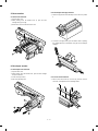
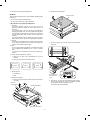
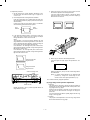
3. Installation procedure
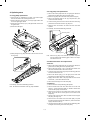
(2) Cassette setting
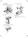
(1) Optical system unlocking
1 Pull out the cassette.
Lift the cassette and slowly pull it out from the copier until it stops.
1 Unlock the No.2/No.3 mirror unit.
Remove the No.2/No.3 mirror unit fixing screw (1 pc.) on the left
side of the copier.
Mirror unit fixing screw
2 Loading copy paper.
Set the copy papers in the cassette. Do not exceed the limit line
indicator.
2 Unlock the No.4/No.5 mirror unit.
Remove the No.4/No.5 mirror unit fixing screws (2 pcs.) on the
right side of the copier.
Mirror unit fixing screw
Gently insert the cassette fully into the copier.
[In the case of SF-1014 with SF-MF14 (Optional) equipped.]
Open the paper feed tray on the right side of the copier.
Remove the No.4/No.5 mirror unit fixing screws (2 pcs.).
Then close the paper feed tray.
Mirror unit fixing screw
4–3
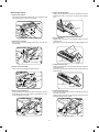
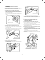
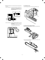
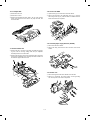
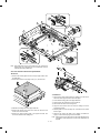
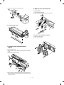
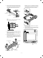
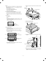
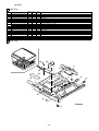
5 Remove the developer tank.
Slightly open the pawl which is fixing the developing unit and the
developer tank with a screw driver, and pull out the developer
tank.
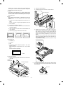
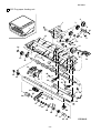
(3) Developer setting
1 Open the front cabinet.
Push the front cabinet open buttons which are on the left and right
sides of the copier, and open the front cabinet.
Developing unit
Front cabinet open button
Developing
tank
Pawl
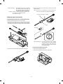
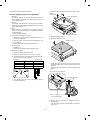
6 Supply developer.
Supply a bag of developer to the developer supply port of the
developing unit.
At that time, move the bag of developer to supply developer evenly.
2 Open the toner cartridge.
While pressing the toner cartridge release lever (B), open the
toner cartridge.
Release lever (B)
Developing
Developing unit
Toner cartridge
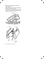
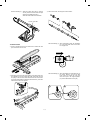
7 Install the developer tank.
Insert the developer tank to the developing unit along the guide of
the developing unit.
At that time, check that the developer tank is securely fixed in the
developing unit.
3 Remove the toner cartridge.
Slowly turn the toner cartridge clockwise to remove.
2
Developing unit
1
Developing tank
8 Install the developing unit.
Slowly insert the developing unit into the copier along the guide of
the copier until it stops.
Tighten the fixing screw which was removed in procedure (D), and
fix the developing unit to the copier.
4 Remove the developing unit.
Loosen the fixing screw (step screw) which is fixing the copier and
the developing unit, and slowly pullout the developing unit and
Lenz hold Plate from the copier.
Fixing screw
(step screw)
Fixing screw
(step screw)
Lenz hold plate
1
2
2
1
Developer unit
Developer unit
4–4
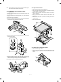
(4) Toner supply
(5) Toner density sensor level check
1 Shake the toner cartridge up and down.
Shake the toner cartridge up and down 9 to 10 times.
1 Turn on the power switch of the copier.
2 Adjust the developer level.
(a) Perform the key operations of simulation 25 sub 2.
2 Install the toner cartridge.
Install the toner cartridge to the copier along the guide of the
copier.
Turn the toner cartridge counterclockwise to lock.
C
0
2
0
C
5
2
With the above key operations, simulation 25 is performed and
the developer is stirred for 3 minutes.
1
(b) After stirring the developer for 3 minutes, the toner density
level is read by the main PWB.
During stirring, the toner density sensor level is displayed on
the MULTI COPY display. (Range: 1 ∼ 99)
[Note] If the simulation is cancelled during execution, the
automatic reading cannot be performed. Do not cancel
the simulation during execution.
2
3 Supply toner.
Remove the sheet from the toner cartridge and supply toner.
Slowly return the toner cartridge to the original position.
(c) Press the CLEAR key three times to cancel simulation 25.
c
c
(6) Accessory attachment
Attach the copy tray.
4 Close the front cabinet.
4–5
c
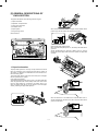
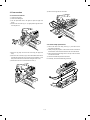
4. Locking procedure for transit or
repacking
In general, reverse the procedures in "3. Installation procedure." For
the optical system lock, perform the following procedure.
(1) No.2/No.3 mirror unit (Mirror base B) lock
1 Perform locking with the unit at its home position (normal copy
position) with the power ON and with the mirror stopped and with
the external covers installed.
Mirror unit fixing screw
2 Lock the unit with the mirror unit fixing screw. (The hole in the left
cabinet)
2 Open the paper feed tray at the right side of the body, and fix the
unit with two fixing screws. (Two holes in the right cabinet)
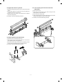
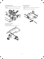
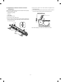
5. Optional multi bypass feeder unit
Installation Manual
(1) Open the upper unit of the main copier unit.
Mirror unit fixing screw
1 Press the release buttons on the left and right sides of the main
copier unit’s front cover, then open the front cover.
2 Push the upper half release lever (green) to the right and down,
then gently open the upper unit.
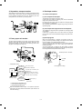
(2) No.4/no.5 mirror unit (Mirror base C) lock
(2) Release the lock for the manual bypass unit and
remove the manual bypass unit.
1 Turn off the power at the 64% position. Perform locking with the
external fitting installed.
1 Release the manual bypass unit by pressing upward on the rock
claws (green; 2 locations) which lock it in place in the main copier
unit’s upper unit.
The manual bypass unit will come out toward you slighly.
2 Open the paper feed tray at the right side of the body, and fix the
unit with two fixing screws. (Two holes in the right cabinet)
2 Pull out upon the manual bypass unit to remove it from the main
copier unit.
Manual bypass unit
Mirror unit fixing screw
[SF-1014 with SF-MF14 (Optional) equipped.]
1 Turn off the power at the 64% position. Perform locking with the
external fitting installed.
Rock claw (latch)
4–6
Rock claw (latch)
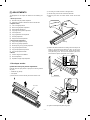
(3) Mount the multi bypass feeder unit onto the
main copier unit.
1 Slide the positioning pins which project from the multi bypass
feeder unit in to the grooves in the main copier unit, then push the
multi bypass feeder unit into place to in stall it.
At this time, to be sure that the multi bypass feeder unit is securely
installed, push down once more on the fourcorners of the unit. (If it
has not been securely installed, "CH" may appear in the COPIES
MADE display when the power is turned on.)
Multi bypass feeder unit
Rock claw (latch)
Rock claw
(latch)
Positioning pins
Positioning pins
Multi bypass
feeder unit
2 Close the upper unit of the main copier unit.
4–7
[5] GENERAL DESCRIPTIONS OF
EACH SECTION
The general descriptions of the following sections are given:
1 Paper feed section
2 Separation, transport section
3 Fuser, paper exit section
4 Developer section
When the CPCF turns off, rotation is stopped, and the takeup roller is
pushed up by the roller release arm spring to the position.
5 Optical system
6 Image forming section
Internal structure
5
6
3
(Manual paper feed operation) Multi
When the solenoid B (MPFS) turns on, the takeup roller falls and the
gate rises.
Almost simultaneously the solenoid A (MPFC) turns on and the
takeup roller and the paper feed roller turns to perform the paper feed
operation.
4
2
1
1. Paper feed section
The paper feed system is in two ways: the tray feed and the manual
feed. The cassette is of the universal type and has the capacity of
250 sheets. It is attached and detached at the front cabinet, that is,
the front loading system.
The manual paper feed is single for the this model. (The multi paper
feed unit (SF-MF14) is an option.)
(Tray paper feed operation)
The cassette paper feed clutch (CPFC) turns on, the paper feed roller
shaft, the paper feed roller, and the takeup roller rotate. At the same
time, the roller release arm is lowered by the limiter spring. As a
result, the takeup roller falls by its own weight to reach the paper
surface, performing the paper feed operation.
ON
When the PPD turns on, the MPFS turns off and the RRC turns on.
Almost simultaneously the MPFC turns off to return the roller and the
gate to the initial state.
OFF
5–1
2. Separation, transport section
4. Developer section
After passing the resist roller section, the paper is transported to the
transfer section. After transfer, the paper is separated from the drum
by the separation electrode and the drum separation pawl, then
transported to the fuser section by the transport belt.
4-1. General descriptions
(1) Two-component developer
The developer is composed of toner and carrier.
Carrier serves as a medium for attaching toner onto the electrostatic
image on the photoconductor drum.
By stirring toner and carrier, they are rubbed to be charged positive
(+) and negative (–) respectively.
Since developer will deteriorate to degrade copy quality, it should be
replaced regularly.
(2) Two-component magnetic brush development
The rotatable non-magnetic sleeve is provided over the magnet roller
and is rotated.
Carrier forms a magnetic brush on the sleeve surface by magnetic
force to attach toner onto the electrostatic image on the photoconductor drum.
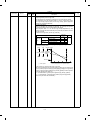
(3) Developing bias
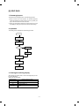
3. Fuser, paper exit section
When the photoconductor is charged and exposed to light (exposure), the surface potential (voltage) of the photoconductor will not
be lost completely. (The residual potential remains.)
Toner is attracted to the photoconductor by this residual potential,
dirtying the photoconductor. As a result, a dirty copy of white background is generated.
To prevent against this, a voltage of the same polarity and higher
than the residual potential is applied to the MG roller, preventing toner
from being attached to the photoconductor surface.
The toner image transferred on the paper is fused by the heat and
pressure of the upper and the lower heat rollers. After fusing, discharge static electricity on the paper with the discharge brush. Then
the paper is discharged to the copy tray.
Residual potential < DV BIAS
MG roller
DV BIAS
-200V
Toner
Carrier
•
Temperature control
Thermistor
CPU
Heat roller
Heater lamp
(Heater trouble)
Self diag display
•
•
•
*
Thermostat
Developing bias voltage
Heat roller surface
temperature detection
The heat roller is heated by the
heater lamp.
(When the heat roller surface
temperature is 180 C˚ or lower,
the heater lamp is actuated)
Contact open (*)
Abnormal high
temperature
Abnormally high temperature (H3)
Abnormally low temperature (H4)
Thermistor disconnection (H2)
When the thermostat contact is open, it is required to press the
reset button in the upper side of the thermostat. (The contact is not
reset automatically.)
5–2
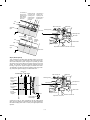
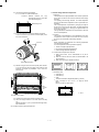
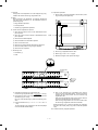
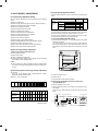
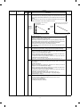
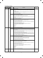
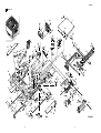
5. Optical system
5-1. General descriptions
• The optical system is composed
of the fixed focus lens and six
mirrors.
Since the fixed focus lens is employed, No.4/No. 5 mirror base is
moved as well as the lens to change the distance between the
document and the drum (OID, Original Image Distance) for reduction and enlargement.
To move the lens and No.4/No. 5 mirror unit, he stepping motor is
driven by the signal from the main control PWB to allow zooming
of 0.70 to 1.22 (inch series: 0.64 ∼ 1.29) with 1% increment. (The
SF-2314 has no zooming function, and its lens and No.4/No.5
mirror base are fixed.)
4
5
16
3
15
10
•
Exposure is adjusted by changing the voltage of the copy lamp.
The copy lamp unit is provided with the AE sensor for detection of
the original density to adjust the light quantity of the copy lamp
according to the original density.
•
For exposure, the slit exposure system is employed where the light
source is moved. (The original table is fixed.)
11
2
1
17
9
7
12
6
8
13
14
1
Copy lamp
2
Reflector
3
No. 1 mirror
4
No. 2 mirror
5
No. 3 mirror
6
Lens
7
No. 4 mirror
8
No. 5 mirror
9
No. 6 mirror
F
No. 2/No. 3 mirror base unit
G
Copy lamp unit
H
No. 4/No. 5 mirror base unit
I
Mirror motor
J
Lens/No. 4/No.5 mirror base drive motor
K
Lens home position sensor
L
Mirror home position sensor
M
Auto exposure sensor
(1) Original table
(2) Copy lamp
The original table is fixed, and originals are set to the left frame side
as the reference.
100V system (285W)
200V system (285W)
(3) Mirror
Six mirrors are used.
No. 1 mirror is provided in the copy lamp, No. 2/3 mirrors at the
No.2/3 mirror base, No. 4/5 mirrors at the No. 4/5 mirror base. The
No.2/3 mirror base is scanned during copying. The No.4/5 mirror
base is moved to change the distance between the original and the
photoconductor during zoom copying.
(4) Lens (Fixed focus lens)
• Construction (One group 3 lenses)
• Brightness (F8)
• Focus
(175mm)
(5) Lens home position sensor (LHPS)
This sensor is used to sense the lens position. The sensor output
signal serves as the basic signal to control the copy magnification
ratio.
(6) Lens base
The lens is mounted to this lens base. It is moved in the paper feed
direction in reduction copying, and in the paper exit direction in enlargement copying.
5–3
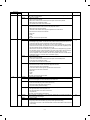
(7) Lens drive shaft
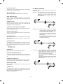
5-2. Basic operations
This shaft is to control the optical axis of the lens in zoom copying.
The lens follows on the slide base shaft.
(Relationship among the original, the lens and the image in each
magnification ratio)
Normal copy: The distance between the surface of original on the
table glass and the lens is made equal to the distance
between the lens and the exposure surface of the
photoconductor to make the original and the image
equal to each other.
(8) Lens drive wire
The wire is used to drive the lens base and the 4/5 mirror base.
(9) No. 4/5 mirror base
The No. 4/5 mirror is installed to this base. It is moved in zoom
copying in order to fit the distance between the original and the
photoconductor.
(10) Mirror motor
The mirror motor is a stepping motor, and used to move the copy
lamp unit and the No. 2/3 mirror base in order to obtain the rpm
corresponding to each magnification ratio.
(11) Mirror home position sensor (MHPS)
Used to sense the home position of the copy lamp unit. This sensor is
a photo transmission type sensor.
Enlargement copy: The lens is nearer to the original when compared
with the normal copy to shorten the distance between the original surface and the lens.
The No. 4/5 mirror base is positioned further
away from the lens to increase the distance between the lens and the exposure surface of the
photoconductor.
The distance between the original and the exposure surface of the photoconductor is greater
than that in the normal copy.
(12) No. 2/3 mirror base
The No. 2/3 mirrors are attached to this base. The mirror base is
scanned by the mirror motor.
(13) Copy lamp unit
This is composed of No. 1 mirror, the thermal fuse, the copy lamp,
the exposure adjustment plate, and the reflector, and is scanned by
the mirror motor.
(14) Thermal fuse
The thermal fuse is closely attached to the reflector in order to
prevent against abnormal temperature rise in the optical system. In
case of abnormal temperature rise, the power for the copy lamp is
turned off.
100V system (117°C)
200V system (117°C)
(15) Reflector
Reduction copy: When compared with the normal copy, the lens
comes closer to the photoconductor to increase the
distance between the original and the lens. The
distance between the lens and the exposure surface of the photoconductor is decreased.
The No. 4/5 mirror base is positioned further away
from the lens.
The distance between the original and the exposure
surface of the photoconductor is longer than that in
the normal copy.
Light from the copy lamp is reflected onto the original.
(16) Exposure adjustment plates
Four exposure adjustment plates are attached to the copy lamp unit
to adjust the exposure balance in the front and the rear frame direction.
(17) Mirror base drive wire
This wire is used to transmit the drive power of the mirror motor to the
copy lamp unit and the No. 2/3 mirror base to scan the mirror base.
(18) Lens drive motor
This is a stepping motor, which is used to move the lens and the No.
4/5 mirror base.
(19) AE sensor
The original density is detected with the intensity of the copy lamp
light reflected from the original. The measurement area is the mirror
base scan area of about 100mm at the center.
The element is a photo diode.
5–4
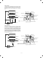
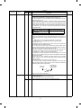
(Optical system dirt correction)
The SF-1014 perform dirt correction by changing the copy lamp intensity according to the dirt degree in the optical system (the copy lamp
unit, No. 1 mirror, No.2 mirror, No.3 mirror) to prevent against remarkable degrading of copy quality.
The reference value is the AE sensor output value which is obtained
when the reference plate is exposed with the copy lamp voltage of
67.7V (135.4V) at power ON.
This value is checked with sim 44-02.
The mirror base scan speed (mirror motor rpm)
is changed to zoom.
The lens and the mirror are
moved to zoom.
Copy paper
feed direction
The mirror scan speed is changed to zoom.
Mirror scan speed
Drum rotating speed < Mirror scan speed
Reference plate (Glass holder)
Table glass
Enlargement
Copy lamp light quantity "UP"
The lens
and the
mirror are
move to
zoom.
Original
Automatic exposure
sensor
CPU
Reference value
> Measured value
Correction data output
Reduction
(Copy lamp control in each copy density)
[MAX. 85V(170V)]
80
70
CLV
(Copy lamp
application
voltage)
60
50
40
[MIN. 40V(80V)]
(V)
EX1
2
3
4
EX5
5–5
6. Copy process
(1) Photoconductor
• This model uses OPC (organic
photoconductor) as photoconduc-
tive material.
OPC layer
CTL (Electric charge moving layer)
CGL (Electric charge generating layer)
Aluminum layer
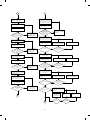
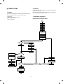
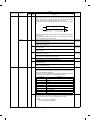
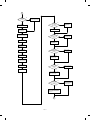
(2) Process diagram
Original
Mirror lens
Copy lamp
High voltage unit
Main corona unit
Discharge lamp
Blank lamp
Exposure
Charging
Discharging
Exposure
High voltage unit
Toner
Development
Waste toner collection
Paper exit
Developer
Cleaning
Cleaning blade
Separation
Fusing
Manual paper feed
Drum upper
image/paper
synchronization
Separation
Resist roller
Paper feed roller
Transportroller
Paper cassette
Transfer
Heat roller
Separation corona unit
Heater lamp
High voltage unit
Transfer charger
Image forming process
High voltage unit
Main corona unit
Blank lamp
Discharge lamp
Developer unit
Cleaning blade
MG roller
Resist roller
Seperation pawl
Seperation corona unit Transfer corona unit
5–6
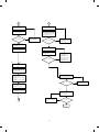
Paper transport path
(3) Actual process
Step 1 (charging)
The OPC drum is negatively charged by corona discharge of the
transfer charger . Positive charges are generated in the aluminum
layer.
Aluminum layer
Main corona unit
Blank lamp
OPC drum
CGL
Discharge lamp
CTL
Developer unit
Cleaning blade
MG roller
Seperation pawl
Resist roller
Seperation corona unit Transfer corona unit
Transfer corona unit
High voltage unit
Step 2 (Discharging)
When the OPC drum is exposed to the discharge lamp light, positive
and negative charges are generated in the OPC drum CGL. The
negative charges move to the positive charges generated in the
aluminum layer in step 1, and the positive charges move to the
negative charges on the OPC drum surface charged in step 1. The
positive charges and the negative charges are neutralized each other
in the aluminum layer and on the OPC drum surface. As a result, the
OPC drum surface potential becomes 20V ∼ 30V.
Discharge lamp
Main corona unit
Light
Blank lamp
Discharge lamp
OPC drum
Developer unit
Cleaning blade
MG roller
CTL
Resist roller
CGL
Seperation pawl
Aluminum layer
Seperation corona unit Transfer corona unit
By performing step 1 (Charging) and step 2 (Discharging), the
photoconductor itself is initialized to stabilize the drum surface potential.
5–7
Step 3 (Main Charging)
By negative discharging of the main charger, uniform negative charges are applied to the OPC drum surface.
The OPC drum surface potential is controlled by the screen grid
voltage to maintain the grid voltage at a constant level.
•
When the drum surface potential is lower than the grid voltage,
electric charges generated by discharging of the charger go
through the screen grid to charge the drum surface potential until it
becomes equal to the grid voltage.
•
When the drum surface potential virtually reaches the grid potential
level, electric charges generated by discharging of the charger
flows through the electrode of the screen grid to the high voltage
unit grid voltage output circuit, thus always maintaining the drum
surface potential at a level virtually equal to the grid voltage.
•
The main corona unit employs the scorotron system to charge the
photoconductor surface to a certain level uniformly.
In addition, the conventional corona wire is replaced with the
corona charging mechanism by saw-teeth plate (stainless steel
plate of 0.1 mm thick). In corona discharge, oxygen molecules in
the air are ionized to generate ozone (O3). The mechanism restrict
the generation of ozone.
Main corona unit
Main corona unit
High voltage unit
Blank lamp
Discharge lamp
Screen grid
Developer unit
Cleaning blade
MG roller
CTL
Resist roller
CGL
OPC drum
Seperation pawl
Aluminum
layer
Seperation corona unit Transfer corona unit
Step 4 (Exposure)
Light from the copy lamp is radiated on the document, and the optical
image of the document is reflected by the mirrors and projected
through the lens to the OPC drum.
The lighter portion of the document reflects more light (high intensity)
to the OPC drum, and the darker portion of the document reflect less
light (low intensity) to the OPC drum. Positive or negative charges are
generated in the CGL of the OPC drum where lights are radiated.
Negative charges generated in the CGL move towards the positive
charges in the aluminum layer generated in step 3. While the positive
charges in the CGL move towards the negative charges on the CPU
drum surface generated in step 3. Therefore, positive charges and
negative charges are neutralized in the aluminum layer and the OPC
drum surface at the light radiating position, decreasing the OPC drum
surface potential. The CGL electric charge generating amount increases in proportion to the document density, that is, reflected light
intensity (the OPC drum surface intensity). Therefore, electric charges are generated less in the CGL layer corresponding to the lighter
density of document (higher intensity of the OPC drum surface), and
a greater quantity of the negative charges on the OPC drum surface
is neutralized, decreasing the OPC drum surface potential more.
On the contrary, electric charges are generated more in the CGL
layer corresponding to the darker density of document (lower intensity
of the OPC drum surface), and less quantity of the negative charges
on the CPU drum surface is neutralized, decreasing the OPC drum
surface less. Therefore, the OPC drum surface potential corresponding to the lighter portion of the document is lower, and that corresponding to the darker portion of the document is higher. Latent
static-electricity images are formed in the above manner.
5–8
Low intensity in
the area corresponding to the
darker density
portion of the
document
Medium intensity
in the area corresponding to the
medium density
portion of the
document
HIgh intensity in
the area corresponding to the
lighter density of
the document
CTL
CGL
Main corona unit
Aluminum
layer
Blank lamp
Discharge lamp
OPC drum
Developer unit
Cleaning blade
MG roller
Surface potential
(High)
CTL
Surface
potential
(Medium)
CGL
Surface
potential
(Low)
Resist roller
Seperation pawl
Aluminum
layer
Seperation corona unit Transfer corona unit
OPC drum
Step 5 (Development)
Toner is attached to the latent static-electricity images on the drum
surface to change them to visible images. The two-component magnetic brush development system charges toner positively by friction
with carriers, and toner is attached to negative charges on the drum
surface. The potential in the darker document projecting area (low
intensity) is high (much negative charges) and attracts more toner.
The potential in the lighter document projecting portion (high intensity) is low (less negative charges), and attracts less toner.
OPC drum
Aluminum layer
CGL CTL
Main corona unit
Higher surface
potential
(Much negative
(charges)
Blank lamp
Discharge lamp
Developer unit
Cleaning blade
Medium surface
potential
(Less negative
(charges)
MG roller
MG roller
Resist roller
Lower surface
potential
(No negative
(charges)
Seperation pawl
-200V
Seperation corona unit Transfer corona unit
High voltage unit
bias voltage
At that time, a bias of –200V is applied to the MG roller (magnet
roller), which is provided for preventing toner from being attracted by
the residual voltage (about –80V to –100V) in the lighter portion after
exposure.
5–9
Step 6 (Transfer)
The transfer paper is charged higher than the OPC drum surface
potential by strong negative discharge of the transfer charger, making
the binding force between the transfer paper and toner stronger than
that between the drum and toner, attracting toner to the transfer
paper.
Aluminum
layer
Main corona unit
Blank lamp
OPC drum
Discharge lamp
CGL
CTL
Toner
Developer unit
Cleaning blade
Transfer paper
MG roller
Seperation pawl
Resist roller
Seperation corona unit Transfer corona unit
Transfer corona unit
High voltage unit
Step 7 (Separation)
After transfer, the copy paper and the drum are negatively charged.
Since, however, the negative potential of the copy paper is higher
than that of the drum, a attraction force is applied between the drum
and the copy paper. To avoid this, AC corona is applied to the copy
paper by the separation charger to decrease the copy paper potential
to the same level as the drum surface potential. The attraction between the copy paper and the drum is weakened by this, allowing
separation of the copy paper by its own extending force. If the copy
paper is not separated by the separation charger, it is separated by
the separation pawl mechanically.
Main corona unit
Aluminum
layer
OPC drum
Blank lamp
Discharge lamp
CGL
CTL
Toner
Developer unit
Cleaning blade
MG roller
Transfer paper
Seperation pawl
Resist roller
Seperation corona unit Transfer corona unit
Seperation corona unit
High voltage unit
5 – 10
Step 8 (Cleaning)
Residual toner on the drum is removed by the cleaning blade. The
removed toner is sent to the waste toner container by the waste toner
transport screw.
Blade
CTL CGL
Aluminum layer
Main corona unit
Blank lamp
Discharge lamp
Developer unit
Cleaning blade
MG roller
Resist roller
Seperation pawl
Residual toner
OPC drum
Seperation corona unit Transfer corona unit
Step 9 (Discharging)
When the OPC drum is exposed to the discharge lamp light, positive
and negative charges are generated in the OPC drum CGL. The
negative charges generated in the CGL move towards the residual
positive charges in the aluminum layer, while the positive charges in
the CGL move towards the residual negative charges on the OPC
drum surface. Therefore, the positive and the negative charges are
neutralized in the aluminum layer and on the OPC drum surface,
removing the residual charges on the OPC drum surface. As a result,
the OPC drum surface potential becomes 20V ∼ 30V.
Discharge lamp
Main corona unit
Blank lamp
Discharge lamp
Developer unit
OPC drum
Residual charge
Cleaning blade
MG roller
CTL
Resist roller
CGL
Aluminum layer
Seperation pawl
Residual charge
Seperation corona unit Transfer corona unit
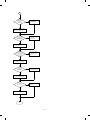
(4) Transit of photoconductor drum surface potential
Transfer
Separate
(OFF)
Clean
DL
Charge
Exposure
BL
Develop
Transfer
-800V
Dark area
-600V
-400V
Developing
bias voltage
-200V
Light area
Residual potential
T (Time)
5 – 11
Separate
Clean
DL
(5) Process correction system
1) Outline of the correction system
This model is provided with the correction system for the optical unit
and the photoconductor drum unit. The combination of the two correction systems provides stable clear copy.
These functions are to maintain the copy quality for a long time and to
correct the characteristics of the parts, and are controlled by the
software and invisible from the outside.
2) Correction operation
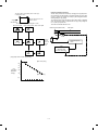
1. Photoconductor drum unit correction (Photoconductor
drum sensitivity correction)
Change the tickness of the carrier transport layer (CTL).
By the developper.
By the cleaner blade.
Cleaner
Develop
OPC drum
Fig. 1
(NEW)
(USED)
Wear down
CTL
CTL
CGL
CGL
Fig. 2
Manual mode exposure 1
VCL
Photo mode exposure 1
Manual mode exposure 5
Correction level
(CL voltage)
Photo mode exposure 5
Correction level is initialized by Simulation 46 or
by replacing the photoconductor drum.
0
100
200
Fig. 3
300
400
500
min
Drum rotating time
The photoconductor drum is subject to mechanical stress by the
cleaning blade, resulting in wear in the OPC layer. In addition to that,
the photoconductor drum receives optical stress from the copy lamp.
These stresses reduce the photo sensitivity of the photoconductor
drum, producing unnecessary dirt copy. This trouble is removed by
adjusting the copy lamp voltage. For this model, however, to reduce
the number of service calls, the copy lamp voltage is automatically
dropped according to the reduction in the photo sensitivity of the
photoconductor drum to correct it.
The drum rotating time from installation of a new photoconductor
drum is counted by the timer and the copy lamp voltage is corrected
in every mode. (Refer to Fig. 3.)
The correction is performed within the range of the max. supply voltage of the copy lamp. (The rotating time of the photoconductor drum
can be checked with Simulation 44-4.)
* The correction level is initialized by Simulation 46 or by replacing
the photoconductor drum.
* Replace the OPC drum for every 40K copies. After replacement,
be sure to reset the drum count value to "0" with SIM 24-7.
The replacement timing of the OPC drum is indicated by lighting
the OPC drum replacement lamp. The copy count of the OPC
drum can be checked with SIM 22-12.
5 – 12
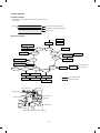
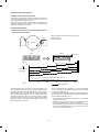
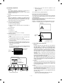
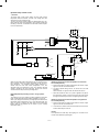
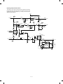
2. Optical unit correction (Dirt correction)
Referance refrection plate
Table glass
Diagram of correction system in the optical section
AE sensor
(Next to the lens)
Referance refrection plate
Copy
lamp
Mirror
AE SENSOR
MAIN CONTROL PWB
CPU
EE-PROM
Timer
AMP
AC power supply unit
(Copy lamp control circuit)
A/D
converter
Copy lamp control
clock generator
Driver
The purpose of this correction is to maintain the copy density even
though the optical unit is contaminated and to reduce troublesome
cleaning of the optical unit.
When the lamp, the mirror, and the reflector are dirtied with dusts and
toner, the light quantity radiated to the photoconductor drum is
reduced, increasing the copy density and producing unnecessary
background copy.
The above trouble is removed by changing the copy lamp voltage to
adjust the copy density. It, however, requires serviceman’s operation.
In this model, the AE sensor senses dirt on the copy lamp, the mirror,
and the reflector, and the copy lamp light quantity is changed according to the dirt level to reduce the change in the copy density due to
the optical unit dirt.
When the optical parts are dirtied, the reflection rate is reduced to
reduce the quantity of light which is passed to the optical dirt sensor.
In this manner the dirt level is sensed.
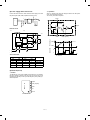
Copy lamp
referance control
level
Arithmetic unit
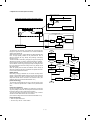
START
The scanner starts
initializing.
Copy lamp voltage
0.3V (0.6V) up
The scanner unit stops
at the standard reflection
plate position.
Correction mode ?
NO
Copy lamp ON
Copy lamp ON
(67.7V/135V)
NO
YES
YES
Copy lamp ON
(67.7V/135V)
Sensor output =
Reference level
(DSENS) ?
NO
Sensor output
< Reference level
(DSENS) ?
YES
Optical dirt sensor
reference level
(DSENS) memory
Copy lamp voltage
0.3V (0.6V) down
No correction is made.
Copy lamp ON
[Initial setting]
After making a copy by Simulation 46, the scanner unit stops at the
position of the standard reflection plate on the back of the document
stopper to light the copy lamp at a certain level, and the AE sensor
output level at that time is recorded as the reference value. (The
reference value can be checked with Simulation 44-2.)
NO
Copy lamp voltage
correction
[Correction timing]
END
The correction is performed after the copy cycle after turning on the
power, or after the specified time of rotation of the photoconductor
drum.
[Correction operation]
The same operation as the initializing is performed to change the
copy lamp voltage until the AE sensor output level reaches the same
level as the reference value, performing the correction.
The copy lamp voltage is revised to a new value at every correction,
and the new value will be used in the next correction.
(The correction voltage value can be checked with Simulation 44-3.)
[Correction timing]
•
•
Sensor output =
Reference level
(DSENS) ?
When the power is turned on.
Once for every 155 min. of drum rotation.
5 – 13
Copy lamp correction
voltage calculation
Sensor output =
Reference level
(DSENS) ?
YES
YES
2 Disconnect the CN-B connector of the lower PWB, remove the
paper feed unit fixing screws (4 pcs.), and lift the paper feed unit
to remove.
[6] DISASSEMBLY AND ASSEMBLY
The descriptions of this chapter are divided into the following sections:
1. Paper feed section, paper transport section, power section
2. Manual paper feed section
3. Fuser section
4. Optical system
5. Drum section
6. Developer section
7. Operation panel/medium cabinet
8. Major parts in the frame side
1. Paper feed section, paper transport
section, power section
1-1. Paper feed unit
1 Open the front cover and open the body. Release the right and
the left lock levers and pull out the manual paper feed unit.
1-2. Paper feed roller ass’y removal
1 Disconnect the connector of the magnetic clutch in the rear frame
side.
2 Remove the hook section of the paper feed roller bearing in the
front frame side by using a screwdriver.
3 Remove the roller release arm spring from the paper feed frame.
2
3
4
6–1
1
4 Remove the bearing in the rear frame and remove the paper feed
roller ass’y.
1-3. Separation roller
1 Remove the paper feed unit and remove the separation roller.
Note for assembly (1): Hang the roller release arm spring on the
spring hook of the roller release arm. Attach the paper feed roller ass’y to the
paper feed unit, and hang the spring on
the paper feed frame.
A
A
Note for assembly (2): Attach the paper feed roller ass’y so that
the paper feed roller clutch faces the
lower frame.
When attaching the paper feed unit, insert
it in the base unit hole of the copier.
1-4. Takeup roller, paper feed roller
1 Remove the paper feed roller ass’y, and remove the takeup roller.
2 Remove the roller holder, the stop ring, and the bearing, then
remove the paper feed roller.
6–2
3 Remove the clutch, and the gear as shown below:
Note for assembly (1): Attach the paper feed roller so that the
one-way clutch in the rear frame side. (Be
careful to the installing direction.)
Attach the roller holder as shown below:
One-way clutch side
Note for assembly (1): When assembling, attach the positioning
pin of the resist roller clutch in the direction of paper exit.
1-5. Resist roller
1 Insert a screwdriver into the front frame hole to release the lock
pawl, and remove the TC case.
Note for assembly (2): When assembling the resist roller ass’y to
the copier, attach it over the PS roller
lower mylar and rotate the mylar and
return the mylar to the original position.
(To prevent deformation of the mylar)
2 Disengage the hook section of the bearing in the front frame side,
lift it upward and remove towards the upper frame side. Remove
the spring in the rear frame side. Disconnect the CN-E connector
in the lower frame PWB unit. Slide the resist roller ass’y to the rear
frame side and remove it upwards.
1
6–3
2
1-6. Transport belt
1-8. Lower unit PWB
1 Remove the fuser unit.
1 Open the body up, and remove the rear lower cabinet.
2 Remove the TC case.
2 Remove the connector, the PWB fixing screw (1 pc.), and the
CN-F fixing screws (2 pcs.). Slide the lower unit PWB to the front
frame side and remove it upwards.
3 Remove the transport belt drive shaft in the TC case from the
holder, and remove the drive shaft in the paper exit side, and
remove the belt.
1-9. Cassette paper empty detector (CPED1)
1 Remove the rear lower cabinet.
2 Remove the fixing screw and the CN-D connector, and remove
CPED1.
1-7. Socket holder unit
1 Remove the CN-C connector of the lower unit PWB, the grounding wire, and the red high voltage lead wire (for separation
electrode) which in the socket holder.
2 Remove the two fixing screws in the paper feed side, remove the
pawl from the positioning hole in the paper exit side, and slide it in
the direction of paper feed to remove.
1-10. Power unit
1 Remove the upper and the lower cabinets in the rear side.
2 Remove 12 connectors, two fixing screws, and the grounding
wire. Lift the power unit to remove it upwards.
6–4
4 Remove the manual arm and the E-ring, and remove the manual
paper feed roller.
Note for assembly (1):
When attaching the harness, be careful to
the connector color and the lead wire
color. (Carefully refer to the indication on
the PWB for connection of the harness.)
Example: YE (WH) → Yellow connector and white lead wire
YE = Yellow, WH = White, BK = Black,
GR = Green, BL = Blue
Note: Gear 20T has a positioning pin. When removing the
manual arm, be careful not to miss the positioning pin.
Gear 20T (Positioning pin included)
2. Manual paper feed section
2-1. Manual paper feed roller, manual takeup roller
1 Remove the manual paper feed unit from the copier.
2 Remove the roller auxiliary spring, the manual solenoid connector,
the E-rings in the front and the rear frames, and the bearing.
Remove the manual roller ass’y together with the solenoid holder.
Arrow mark
Note for assembly (1): The manual paper feed roller is provided
with the one-way clutch. When attaching
it, attach so that the arrow mark on the
roller is in the E-ring side. (Be careful to
the installing direction.)
2-2. Reverse rotation roller ass’y
3 Remove the manual feed takeup roller from the manual arm.
1 Remove the manual feed roller ass’y.
2 Remove the reverse roller ass’y from the roller holder.
6–5
8 Remove an E-ring and two connectors.
3. Fuser section
3-1. Fuser unit removal
1 Open the front panel
2 Remove the table glass.
3 Turn the open/close lever to the right and open the upper unit
slowly.
4 Remove the connectors (2 pin × 2), slightly lift the right side of the
unit and pull it out.
3-2. Heater lamp replacement
1 Remove the fuser cover fixing screw (1 pc.), and slide it to the
front side, and remove it.
2 While pushing the projection of the Faston terminal connected to
the thermostat, remove the lead wire from the connected section.
5 Move the copy lamp unit to the left of the body (the paper exit
side).
3 Remove the lamp holder fixing screw on the top of the rear frame,
and remove the holder.
6 Disconnect the connector (2-pin) of the dehumidifier heater which
extends from the dark box cover. Insert a long screwdriver (+) into
that port and remove the screw which is fixing the fuser cover.
4 Pull out the heater lamp from the front frame.
For assembly, reverse the disassembly procedures.
7 Remove the fuser cover in the direction of arrow A.
A
6–6
3-3. Upper heat roller ass’y removal
3-5. Lower cleaning roller and lower heat roller
replacement
1 Remove the bearing fixing screws (2 pcs.) in the front and the rear
frames.
1 Remove the fuser unit.
2 Put the paper guide to the paper exit side and separate the
separation pawl from the roller and fix it.
2 Remove the CL roller springs (2 pcs.) which is fixing the lower
cleaning roller from the hook section.
3 Rotate the fixing screw section of the bearing about 45 degrees
below and pull it upwards.
3 Remove the lower cleaning roller.
4 Lift the paper exit guide, and remove the lower heat roller without
making contact between the roller and the scraper.
For assembly, reverse the disassembly procedures.
For assembly. reverse the disassembly procedures.
3-4. Upper separation pawl replacement
1 Remove the fuser unit and remove the cover.
2 Place the fuser unit so that the paper guide is in the lower side.
(The separation pawl is in the upper side.)
3 Remove the tension spring, hold the tip of the separation pawl and
remove it from the supporting section, and tilt it to remove.
For assembly, reverse the disassembly procedures.
6–7
3-6. Scraper replacement
3-7. Thermistor/thermostat removal
1 Remove the upper fuser unit.
2 Remove the paper exit paper guide fixing screw (step screw) in
the front frame side, and remove the paper exit paper guide.
Press this projection to desassemble
Paper exit paper guide
3 Remove the scraper hook section from the paper exit paper guide,
and remove the scraper.
* Note for assembly
Scraper
Note: When attaching the scraper, be careful not to deform it. Also
be careful to check that the scraper hook section is completely
inserted into the paper exit paper guide.
6–8
•
Be sure to bring the thermistor center into contact with the heat
roller.
•
Clean and remove foreign materials from the thermistor surface
with alcohol.
4. Optical system
4-2. Copy lamp unit replacement
4-1. Copy lamp replacement
1 Remove the manual paper feed unit, the right upper cabinet, the
glass holder, the table glass, and the operation panel.
2 Move the copy lamp unit to the frame notch (refer to the figure).
1 Open the body up. Release the lock lever of the manual paper
feed unit and remove the manual paper feed unit.
3 Remove the terminal section of the copy lamp lead wire. (One
screw and insertion terminal)
2 Remove the fixing screws (2 pcs.) in the right upper cabinet, and
remove the right upper cabinet.
4 Loosen the fixing screw of the front and the rear frame wire, fixing
plate and remove the wire from the copy lamp unit.
3 Remove the fixing screws (4 pcs.) of the glass holder, and remove
the glass holder.
5 Slide the whole unit forward, and remove the rear frame side
upwards.
4 Remove the table glass.
For assembly, reverse the disassembly procedures.
Wire fixing screw
Wire fixing screw
5 While pushing the copy lamp electrode in the rear frame, remove
the copy lamp.
Note: When the copy lamp unit is removed, the position adjustment
must be required when attaching again. Refer to the adjustment item for the work.
4-3. Mirror base drive wire replacement
<Removal>
1 Remove the manual paper feed unit, the right upper cabinet, the
glass holder, the table glass and the operation panel.
2 Remove the fixing screws (2 pcs.) of the left upper cabinet, and
slide to the rear frame side to remove the cabinet.
3 Loosen the fixing screw of the copy lamp unit wire fixing plate, and
remove the wire from the unit.
4 Remove the tension spring (7 in the figure) of the mirror base
drive wire in the paper exit side from the hook section.
5 Slightly shift the mirror base to the paper feed side, and remove
the terminal 1 of the mirror base drive wire.
6 Remove the wire fixing screw of the drive pulley.
<Installation>
For assembly, reverse the disassembly procedure.
1 Set the mirror base to the positioning plate position.
Note: Be careful to the direction of the copy lamp installation.
2 Set the terminal side of the mirror base drive wire on the hook
section 1, turn the mirror base pulley 2 outside to wind the wire
around the drive pulley from the above.
3 Wind the wire 8 turns from the outside to the inside of the drive
pulley, and put the 7th turn into the groove, and fix it with a screw
temporarily.
4 Pass the wire under the mirror base and wind around the paper
exit pulley (the larger one).
5 Pass the wire to the inside of the mirror base pulley, and pass
through the paper exit pulley (the smaller one), then fix the tension
spring to the hook section 7.
6 Check that the mirror base is in contact with the positioning plate,
and tighten the wire fixing screw of the drive pulley.
6–9
2
5
4
7
2
7
6
6
3
5
5
4
1
2
5
1
3
2
Note: After replacement of the mirror base drive wire, perform the
vertical skew copy adjustment, the focus adjustment, and the
horizontal skew copy adjustment.
4-4. Lens and lens drive wire replacement
<Removal>
1 Remove the manual paper feed unit, the right upper cabinet, and
the table glass.
2 Remove the dark box cover fixing screw (1 pc.) and the cover.
<Installation>
1 Pass the lens drive shaft through the carriage unit, and set the
shaft to the shaft support section of the base plate.
2 Fix the shaft mounting plate in the paper feed side.
3 Store the lens unit projection in the lens guide rail.
4 Set the lens drive wire on the carriage unit.
5 Align the No.4/5 mirror zoom cam and the carriage unit to the
normal copy position
3 Shift the lens carriage unit to the paper feed side.
6 Manually hold and fix the carriage unit, and wind the wire around
the drive gear.
4 Remove the tension spring of the lens drive wire from the hook
section, and remove the wire.
7 Wind the wire around the pulley, pull it slightly and attach the
spring to it, and set the spring on the hook section.
5 Remove the shaft mounting plate in the paper feed side, and
remove the shaft and the carriage unit.
Note: When the lens unit is removed, the right angle adjustment, the
magnification ratio adjustment, and the focus adjustment are
required.
6 – 10
Note: When the lens drive wire is removed, the magnification adjustment and the focus adjustment are required.
4-6. Optical unit removal
4-5. No. 4/5 mirror unit and peripheral parts
replacement
2 Remove the right cabinet, the left cabinet, the operation panel, the
medium cabinet, and the rear cabinet.
1 Remove the drum unit and the developer unit.
3 Remove three connectors A from the sensors in the rear as
shown in the figure.
1 Remove the manual paper fed unit, the right upper cabinet, and
the table glass.
4 Remove connector B between the mirror motor and the main
PWB (CN-C).
2 Remove the dark box cover fixing screw (1 pc.) and remove the
cover.
3 Remove the mirror holder spring.
5 Remove two snap bands C which are binding cables of the
operation panel.
4 Remove the shaft mounting plate, pull out the shaft towards the
paper feed side, and remove No. 4/5 mirror unit.
6 Remove the optical unit .
C
A
B
A
5 Remove the fixing screw of the center section of the drive pulley,
and remove the pulley.
4-7. Other parts in the optical system
1 Remove the rear upper cabinet.
2 Remove the CN-C connector of the main PWB and the fixing
screws (2 pcs.), and pull out the mirror motor towards the rear
frame.
6 Remove the CN-E connector of the main PWB, remove the drive
motor fixing screws (2 pcs.), and remove the No.4/5 mirror unit
from the mounting section (square hole in the base plate).
For assembly, reverse the disassembly procedures.
6 – 11
3 Remove the connector and the fixing screw (1 pc.), and remove
the mirror home position sensor (MHPS) towards the rear frame.
4-8. Light adjustment plate/temperature fuse
removal
4 Remove the connector and the fixing screw and pull out the lens
home position sensor (LHPS) towards the rear frame.
1 Remove the document glass.
2 Remove the parts as shown in the figure.
5 Remove the fixing screw (1 pc.) of the upper frame and the screw
and the connector in the rear frame, then remove the main PWB.
6 Remove the connector, the manual paper feed unit, the right
upper cabinet, the table glass, and the dark box cover. Remove
the fixing screw from the above and remove the AE sensor
towards the front frame side.
For assembly, reverse the disassembly procedures.
6 – 12
5. Drum section
6-2. Developer cartridge removal
5-1. Drum unit removal
1 Place the magnet roller of the developer unit on the box to protect
it.
1 Open the front cover.
2 While pressing down the release lever A, open the toner
cartridge slowly. (Arrow B)
3 Remove the screw and remove the drum unit.
A
2 As shown in the figure below, open the section which is pressing
the cartridge pawl with a screwdriver, and pull out the developer
cartridge.
B
6. Developer section
6-1. Developer unit removal
1 Open the front cover.
2 While pressing down the release lever, open the toner cartridge
slowly and remove it.
3 Loosen the step screw A.
6-3. Toner motor removal
4 Pull out the developer unit.
1 Remove four short screws A and one long screw B, and the
connector, and separate the toner cartridge section.
A
6 – 13
2 Remove two screws C and remove the motor.
8. Major parts in the frame side
8-1. Ozone filter
1 Remove the document glass.
2 Remove the black sheet and remove the ozone filter.
6-4. Toner density sensor
8-2. Optical unit cooling fan removal
1 Remove the rear cabinet.
2 Remove as shown below.
7. Operation panel section/medium
cabinet
1 Open the front cabinet.
2 Remove three screws A and two harnesses from the operation
panel.
3 Remove the operation panel unit.
A
A
B
A
B
4 When removing the medium cabinet, first remove the process unit
and the developer unit then remove four screws B and remove
the medium cabinet.
6 – 14
8-3. Ventilation fan motor
8-5. Paper exit sensor
1 Remove the optical unit. (For details, refer to "4. Optical unit
removal.")
1 Open the front panel.
2 Move the open/close lever to the right and open the upper unit
slowly.
2 As shown in the figure below, remove the ventilation fan motor.
3 Remove the sensor as shown in the figure below.
8-4. Transport roller clutch
1 Remove the rear cabinet.
2 Remove the transport clutch as shown in the figure below.
6 – 15
[7] ADJUSTMENTS
2 Tie a string to a needle as shown in the figure below.
The descriptions of this chapter are divided into the following sections:
4 Mark the point where the needle makes contact with the MG
3 Hold the string and move the needle to the MG roller.
roller.
1. Developer section
(1)
MG roller main pole position adjustment
(2)
Adjustment of clearance between DV doctor and MG roller
2. Optical section
(1)
Lens unit angle adjustment
(2)
Mirror unit angle/position adjustment
(3)
Image distortion adjustment
(4)
Copy image center position adjustment
(5)
Focus adjustment
(6)
Copy magnification ratio adjustment
(7)
Uniformity adjustment
(8)
Image loss/void area adjustment
3. Copy density adjustment
(1)
Copy Density adjustment timing
(2)
Note for copy density adjustment
(3)
Necessary thing for copy density adjustment
(4)
Copy density adjustment mode
(5)
Copy density adjustment procedure
(6)
Copy density adjustment table
Marking
5 Measure the distance between the marking and the developer unit
bottom A and check that the distance is within 15.1mm. If the
measured distance is outside the range, loosen the MG adjustment plate fixing screw, and move the adjustment plate in the
arrow direction to perform procedures 3 to 5 again.
4. Others
(1)
Transfer charger wire installation
(2)
DV bias adjustment
(3)
Separation charger output adjustment
1. Developer section
(1) MG roller main pole position adjustment
If the MG roller main pole position is improper, the following troubles
may occur:
•
•
A
Insufficient copy density
Toner splash
15.1mm
1 Remove the DV unit from the body and remove the DV cover.
DV cover
6 Tighten the MG adjustment plate fixing screw.
7–1
4 Press the DV doctor in the arrow direction and tighten the DV
(2) Adjustment of clearance between DV doctor
and MG roller
doctor fixing screw.
5 Check that the clearance of the DV doctor is 0.625 ±0.03mm in
If the clearance between the DV doctor and the MG roller is improper,
the following troubles may occur:
•
•
•
the range of 30mm width under the DV doctor fixing screw.
Insufficient copy density
0.625±0.03mm
Copy dirt
Toner splash
1 Remove the DV cover.
2 Loosen the DV doctor fixing screw.
3 Insert a 0.625mm thickness gauge into the clearance between the
MG roller and the DV doctor in the range of 30mm width under the
DV doctor fixing screw.
MG
A
Note: When adjusting, be careful not to scratch the DV doctor.
A
30mm
30mm
7–2
2. Optical section
A. Adjustments list
Classification
No.
(1)
Parts installation
position
(2)
Adjustment content
Lens
Mirror
a
a
b
Copy picture quality
(3)
a
Image distortion adjustment
b
(4)
(5)
(6)
Copy image center position adjustment
Focus adjustment (Resolution
adjustment)
Copy magnification ratio adjustment
a
b
c
(7)
(8)
Uniformity adjustment
Image loss, void area adjustment
a
b
Lens unit right angle adjustment
No.4/5 mirror unit right angle
adjustment
No. 4/5 mirror unit drive cam position
adjustment
Horizontal image distortion adjustment
Vertical image distortion adjustment
Vertical copy magnification ratio
adjustment (normal copy)
Vertical copy magnification ratio
adjustment (zoom copy)
Horizontal copy magnification ratio
adjustment (zoom copy)
Copy image position adjustment
Lead edge void area adjustment
End edge void area adjustment
Adjustment
value/Standard
value
Necessary
special tool
Ref.
page
—
—
7-6
—
—
7-7
—
—
7-8
—
—
7-8
—
—
7-11
0 ±1.5 mm
—
7-12
*
—
7-14
100 ±0.8%
—
7-15
100 ±0.9%
—
7-16
100 ±0.8%
—
7-16
—
—
7-18
*
—
7-19
*
—
7-23
* For details, refer to the Ref. page.
B. Notes
When performing the adjustment, observe the following notes:
START
1)
Observe the sequence of procedures shown in the flowchart
below.
2)
Adjustment can be started midway in the flowchart only if all the
previous items have been properly adjusted.
3)
If the content of an adjustment item in the flowchart is changed,
all the following items must be adjusted accordingly.
Any adjustment item is based on the previous adjustment items
and relates to the following adjustment items.
4)
(1)-a
(2)-a
Adjust the lens unit inclination
to zero.
Execute Sim26-08 to set the lens
reference position set value in the
zoom copy mode.
Adjust No.4/5 mirror unit inclination
to zero.
(2)-b
"Sim" in the flowchart stands for "Simulation."
Check the lens No. (OL No.)
Obtain the lens reference position set
value from the lens No. table.
Set to the normal copy state in the
normal copy mode and set the lens
unit to the normal position. Then fix the
No.4/5 mirror drive cam position to the
specified position.
Fix the blank lamp to the center.
Execute Sim48-1 to set the lens
reference position set value.
(4)
Fix the lens center position adjustment
rail at the center temporarily.
Obtain the lens reference position set
value in the zoom copy mode from the
lens No. table.
(5)
Fix No.4/5 mirror position to the
center.
1
Standard setting value in the sim48-1 and 26-8 (Reference)
Lens No.
–1
0
1
2
3
4
5
6
7
8
9
10
11
12
sim48
77
75
73
72
70
68
67
65
63
61
60
58
56
55
6
7
8
9
10
11
12
13
sim26-8
0
1
2
3
4
5
Lens No.
13
14
15
16
17
18
sim48
53
51
49
48
46
44
sim26-8
14
15
16
17
18
19
7–3
1'
2'
(3)-a
Make a test chart. (Draw a rectangle
NO
on B4 or 8 1/2" x 14" paper.)
(5)
With the document cover open,
make a 90% copy on B4 or
8 1/2" x 14"paper.
Use the test chart (UKOG-0089CSZZ)
or the resolution chart to make a NO
100%
copy on B4 or 8 1/2" x 14" paper so
that the resolution patterns are copied
at the center and the four corners.
Check the resolution at the center
and the four corners.
Check horizontal image distortion.
The
distances at the
right and the left of the horizontal
copy image line and the black background
made by the blank lamp are equal
to each other.
NO
Change the relative positions of
the rear or the front frame side
scanner drive pulley and the
shaft, and adjust horizontal
image distortion.
(6)-a
With the document cover closed,
make a 10% copy on B4 or
8 1/2" x 14" paper.
Change No.4/5 mirror positions
to adjust focus.
YES
Compare the scale and its copy
image size.
Check that the right corner and the left
corner angles of the copy image are
right angles.
Is the
right corner angle
of the copy image equal
to the left corner
angle ?
NO
Set the scale along the document
reference plate (vertical to the paper
transport direction) and make a 100%
copy on B4 or 8 1/2" x 14" paper.
YES
(3)-b
Is the center
resolution more than
5.0 lines/mm and are the corner
resolutions more than
4.5 lines/mm ?
YES
NO
Change the height balance of
right and left scanner slide rails,
and adjust so that the corner
angles of the copy image
rectangle are equal to each
other.
NO
Are they the same size ?
Is the copy
image greater than the
actual scale ?
NO
YES
(6)-b
Make a copy on B4 or 8 1/2" x 14"
paper at the max. enlargement ratio.
(Zoom model only)
YES
With the document cover closed,
make a 100% copy on B4 or
8 1/2" x 14" paper.
Check that the max. enlargement ratio
matches with the copy image size.
Set the Sim26-8 set value smaller.
Check the copy image vertical
distortion.
//9/
Are the
four angles of the copy
image rectangle right
angles ?
Set the Sim48-1 set value greater.
Set the Sim48-1 set value smaller.
Set the Sim26-8 set value greater.
YES
NO
Are the
enlargement ratio and
the copy image size
matched ?
Change No. 4/5 mirror height
balance and adjust vertical
image distortion.
Is the copy
image greater for the
enlargement ratio ?
NO
YES
(6)-c
YES
NO
Set the scale in the paper transport
direction, and make a copy on B4 or
8 1/2" x 14" paper at 100%.
Make a test chart. (Draw a rectangle at
(4) the center of B4 or 8 1/2" x 14" paper in
the longitudinal direction.)
Set the test chart to the document
positioning reference plate, and make
a 100% copy on B4 or 8 1/2" x 14"
paper by cassette paper feed.
Compare the scale and its copy
image size.
Set Sim48-2 set value smaller.
Set the Sim48-2 set value greater.
YES
Check that the copy image is at the
center of the copy paper.
Are they the same size ?
NO
Is the copy
image greater
than the actual
scale ?
NO
YES
Is the
copy image at the
center of the copy
paper ?
NO
Change the lens rail position so
that the copy image comes at
the center of the copy paper.
YES
Is the SPF installed ?
YES
Set a document with the fixed size
images in the SPF mode and make
a copy on B4 or 8 1/2" x 14" paper
at 100%.
NO
Compare the scale and
the copy image in the
paper transport direction.
2
Set the Sim48-3 set value
smaller.
Set the Sim48-3 set value
greater.
YES
YES
3
7–4
Are they the
same size ?
NO
Is the copy
image greater than
the actual scale ?
NO
3'
4'
Use a half-tone document and make a
100% copy on B4 or 8 1/2" x 14"
paper in the half tone mode.
Make copies at the max. enlargement
ratio and the min. enlargement ratio.
(7)
Measure the distances between the
copy image lead edge and the copy
paper lead edge of the max. enlargement copy and the min. enlargement
copy, and compare the two.
Check the uniformity.
Is the uniformity OK ?
NO
Change the installing position of
the exposure adjustment plate
to adjust the uniformity.
0 ± 1.0 mm ?
NO
Change the Sim50-1 set value A
so that the difference is within
the specified range.
YES
Put the scale to the document
reference plate and set in the paper
transport direction.
Make a 100% copy with Sim50-1.
Set the Sim45 set value to "0."
Measure the distance between the
copy image lead edge and the copy
paper lead edge.
0 ± 1.0 mm ?
(8)-a
Change the Sim50-1 set value
B so that the difference is
within the specified range.
(SF-2414/2514)
NO
Change the Sim50-1 set value
A so that the difference is
within the specified range.
(SF-2314)
YES
YES
Set the Sim50-1 set values A and B
to "0."
Make a copy on B4 or 8 1/2" x 14"
paper at the max. enlargement ratio
and the min. reduction ratio in the
document table mode.
(8)-b
Measure the distance between the
copy image lead edge and the paper
lead edge of each copy.
L1 = Distance in the max. enlargem
ent ratio
L2 = Distance in the min. reduction
ratio
Make a 100% copy in the document
table mode and check the lead edge
void area. (Document table mode)
0 +3
-0 mm ?
Calculate the Sim50-1 set value from
the following formula.
A = 8.243 x (L1 - L2)
B = 16.0668 x L2 -7.9661 x L1
YES
NO
Set the Sim50-1 set values A and B.
Use a black color document and
make a 100% copy on the A4 or
8 1/2" x 14" paper
YES
4
Change the Sim45-1 set value
to adjust the end edge void
area.
NO
1 ~ 3mm ?
YES
End
7–5
NO
Change the Sim45-1 set value
to adjust the void area.
C. Adjustment contents
Optical unit cover
(1) Lens
a. Lens unit right angle adjustment
I. Summary
By setting the optical axis of the copier body and that of the lens
in parallel with each other, copy image distortion due to the lens
can be reduced.
The horizontal angle of the lens unit slide shaft is changed by
changing the position of the lens unit slide shaft fixing plate.
This adjustment is performed not by checking a copy image, but
by visual measurement with the mark on the optical unit base as
the reference.
The copy image distortion must be adjusted not only in this
adjustment but also in the mirror parallelism adjustment.
II. Purpose
The purpose of this adjustment is to reduce copy image distortion due to the lens by setting the optical axis of the copier body
and the optical axis of the lens in parallel with each other.
4) Hold section A of the lens unit slide, and move the lens unit
side section to the mark on the optical unit base.
III. Note
The copy image distortion adjustment is completed by making a
copy and adjusting parallelism of the mirror.
For that purpose, this adjustment must have been properly performed.
Section A
IV. Cases when the adjustment is required
1) When the lens or the lens unit is disassembled or its part is
replaced.
2) When the copy image is distorted as follows (because of
different copy magnification ratios in different sections):
Large copy
magnification ratio
Normal copy
magnification ratio
Document
Copy
Small copy
magnification ratio
Optical unit
base
V. Necessary tool
Mark
* Screwdriver (+)
VI. Adjustment procedure
1) Remove the right upper side cabinet and the document reference plate.
5) Loosen the lens unit slide shaft fixing screw.
Document
reference plate
Document table glass
B
A
Center mark
Lens unit slide shaft
fixing plate
Right upper side cabinet
2) Remove the document glass.
A
B
6) Fix the lens unit slide shaft fixing plate in the center mark
position.
3) Remove the optical unit cover.
7–6
VII. Troubles caused by improper adjustment
2) Remove the document glass.
(2) Mirror
Optical unit cover
There are following adjustments of parts installation positions related
to the mirror.
* No. 4/5 mirror unit right angle adjustment
* No. 4/5 mirror unit drive cam position adjustment
a. No. 4/5 mirror unit right angle adjustment
I. Summary
Copy image distortion caused by No. 4/5 mirror unit van be
reduced by setting the optical axis of the copier and No. 4/5
mirror unit.
The horizontal angle of the lens unit slide shaft is adjusted by
changing the position of No. 4/5 mirror nit slide shaft fixing plate.
This adjustment is performed not by checking a copy image but
by visual measurement with the optical unit base plate as the
reference.
Copy image distortion must be adjusted ont only in this adjustment but also in the No. 1/2 scanner unit parallelism adjustment.
II. Purpose
The purpose of this adjustment is to eliminate copy image distortion by setting the optical axis of the copier and that of the No.
4/5 mirror unit in parallel with each other.
3) Loosen the fixing screw of the No. 4/5 mirror unit slide shaft
fixing plate.
III. Note
The copy image distortion adjustment is completed by making a
copy and adjusting the parallelism of No. 1 and No. 2 scanner
units.
For that purpose, this adjustment must have been properly performed.
IV. Cases when the adjustment is required
1) When No. 4/5 mirror unit is disassembled or its part is
replaced.
2) When the copy image is distorted as follows:
Document
Copy A
Copy B
B
A
V. Necessary tools:
* Screwdriver (+)
No. 4/5 mirror unit
slide shaft fixing
screw
* Scale
VI. Adjustment procedure
1) Remove the right upper side cabinet and the document reference plate.
A
B
4) Move the No. 4/5 mirror unit slide shaft fixing plate in directions A and B so that the No. 4/5 mirror unit side is in parallel
with the optical unit frame side plate, and fix it.
Use a scale to check the parallelism.
Document
reference plate
Document table glass
Right upper side cabinet
7–7
VII. Trouble caused by improper adjustment
5) Loosen the No. 4/5 mirror unit drive cam fixing screw without
moving the lens unit drive gear.
b. No. 4/5 mirror unit drive cam position adjustment
I. Summary
The copy magnification ratio and focus are properly adjusted by
matching the lens unit movement and the No. 4/5 mirror movement.
This adjustment is performed by changing the relative positions
of the lens unit drive gear and the No. 4/5 mirror unit drive cam.
II. Purpose
The purpose of this adjustment is to adjust the relative positions
of the lens unit drive gear and the No. 4/5 mirror unit drive cam
and to adjust the copy magnification ratio and the focus.
Cam
III. Note
IV. Cases when the adjustment is required
Do not move
1) When the lens and the No. 4/5 mirror drive section are disassembled or its part is replaced.
Cam fixing screw
2) When the focus is improper though the copy magnification
ratio is proper, or vice versa.
6) Turn the No. 4/5 mirror unit drive cam without moving the
lens unit drive gear so that the cam positioning hole is fit with
the reference hole in the optical unit frame.
V. Necessary tools
* Screwdriver (+)
Requires changing relative
position of cam and gear
when having an out of focus
copy in the enlargement
reduction copy mode
* M4 x 20 screw
VI. Adjustment procedure
1) Set the copy magnification ratio to 100%, and set the lens
unit to the position for 100% copy magnification ratio.
Standard fixing position
2) Remove the right side cabinet and the document reference
plate.
Document
reference plate
Document table glass
Frame
Cam fixing
screw
Reference
hole
Do not move.
7) Pass the M4 x 20 screw through the No. 4/5 mirror unit drive
cam positioning hole and fix the screw to the frame without
turning the cam.
8) Tighten the cam fixing screw to fix the No. 4/5 mirror unit
drive cam to the lens unit drive gear without moving the lens
unit drive gear.
Right upper side cabinet
3) Remove the document glass.
9) Remove the screw which was fixed to the frame in procedure
7).
4) Remove the optical unit cover.
Optical unit cover
VII. Troubles caused by improper adjustment
(3) Image distortion adjustment
There are following two types of image distortion.
* Horizontal image distortion
* Vertical image distortion
Image distortion is generated mainly by insufficient parallelism of the
mirror and misalignment of the lens optical axis.
In this model, image distortion is adjusted by adjusting parallelism of
each mirror.
a. Horizontal image distortion adjustment
7–8
I. Summary
This adjustment is to adjust horizontal image distortion by setting
the horizontal optical axis of the copier and the horizontal optical
axis of each mirror in parallel with each other. The relative positions of the front frame and the scanner unit drive pulley of the
frame are changed to perform the above adjustment.
2) Remove the document glass.
Install the No. 1 and No. 2 scanner units to the specified positions, adjust the mechanical horizontal parallelism, and perform
the final adjustment while making copies.
3) Loosen the fixing screw of the No. 1 scanner unit wire.
II. Purpose
The purpose of this adjustment is to reduce horizontal image
distortion by setting the horizontal optical axis of the copier and
the No. 1 and No. 2 scanner unit horizontal optical axis in parallel with each other.
Wire fixing screw
III. Note
Before starting this adjustment, the following items must have
been completed. If not, this adjustment cannot reduce image
distortion.
* The lens unit right angle adjustment must have been completed.
* The No. 4/5 mirror unit right angle adjustment must have
been completed.
IV. Cases when the adjustment is required
1) When the No. 1 and No. 2 scanner units are disassembled or
their part is replaced.
Wire fixing screw
2) When the scanner unit drive section is disassembled or its
part is replaced.
4) Manually turn the scanner unit drive gear to bring No. 2
scanner unit into contact with No. 2 scanner unit positioning
plate. When No.2 scanner unit makes contact with No.2
scanner unit positioning plate in the rear frame side simultaneously, the mechanical parallelism of No.2 scanner unit is
proper.
If one side of No.2 scanner unit makes contact with No.2
scanner unit positioning plate and the other side does not,
the parallelism is improper.
If the parallelism is improper, perform the procedure of step
5).
3) When the copy image is distorted as shown below:
Document
Copy A
Copy B
V. Necessary tools
* Screwdriver (+)
* Hex wrench
* Scale
* Test chart for distortion adjustment (Make a chart shown
below by yourself.)
Draw a rectangle on a paper (B4 or 8 1/2" x 14") as shown
below.
Be sure to make four right angles.
L=10mm
VI. Adjustment procedure
1) Remove the right upper side cabinet and the document reference plate.
Document
reference plate
Document table glass
5)
Loosen the scanner unit drive pulley setscrew in the side where
No.2 scanner unit does not make contact with No.2 scanner unit
positioning plate.
Set screw
Scanner unit drive pulley
Right upper side cabinet
7–9
6)
Procedures 1) to 8) are for adjustment of mechanical
horizontal parallelism. No.1 scanner unit and No.2 scanner
unit are fixed to the specified positions and the mechanical
horizontal parallelism of No.2 scanner unit is adjusted.
Without moving the scanner unit drive pulley shaft, manually turn the scanner unit drive pulley in the same side of the
loosened setscrew. When it makes contact with No.2 scanner unit positioning plate, tighten and fix the setscrew.
Do not move
the shaft.
No.2 scanner unit
Positioning plate
Scanner unit drive pulley
(Note)
Allow a clearance of about 0.5mm between the scanner
unit drive pulley and the positioning E-ring.
Then the optical horizontal parallelism must be adjusted in
the following procedures.
9)
Set the image distortion check chart on the document table,
and make a reduction copy (90%) on an B4 or 14" x 8 1/2"
paper with the document cover open.
0.5mm
7)
8)
Manually turn the scanner unit drive gear to bring No.2
scanner unit into contact with the positioning plate, and
perform the procedure of step 4).
Repeat procedures of steps 4) to 7) until the parallelism of
No.2 scanner unit is properly set.
50mm
With No.2 scanner unit being in contact with No.2 scanner
unit positioning plate, and insert the 1.0 mm spacer between No.1 scanner unit and upper-R frame, bring No.1
scanner unit into contact with upper-R frame, and fix it to
the scanner unit drive wire.
No.1 scanner unit
Upper-right frame
B4 or "11 x 14" size
paper
Wire fixing
screw
Wire fixing
screw
1.0mm spacer
7 – 10
10) Check the horizontal image distortion.
If LL = LR, there is no horizontal distortion.
b. Vertical image distortion adjustment
I. Summary
This adjustment is to adjust parallelism of the vertical optical axis
of the copier and that of each mirror to eliminate vertical image
distortion.
For adjusting vertical image distortion, the overall adjustment
and the right-left balance adjustment must be performed independently.
The overall adjustment is performed by changing the height of
No.4/5 mirror unit in the front frame side. The right-left balance
adjustment is performed by changing the right-left balance of
No.2 scanner unit rail.
The right-left balance adjustment must be performed in advance
to the overall adjustment.
LL and LR = Distance between the copy
horizontal line and the outer edge
of the black background
LL
LR
Black background
11) If LL is not equal to LR, perform the following procedure.
Loosen the setscrew of the scanner unit drive pulley in the
front or the rear frame.
II. Purpose
The purpose of this adjustment is to set parallelism of the vertical optical axis of the copier and that of No.4/5 mirror unit and
No.2 mirror unit to eliminate vertical image distortion.
III. Note
Before performing this adjustment, the following adjustments
must have been completed.
If not, this adjustment cannot be performed properly.
* The lens unit right angle adjustment
* No.4/5 mirror unit right angle adjustment
* Horizontal image distortion adjustment
Set screw
IV. Cases when the adjustment is required
1) When No.4/5 mirror unit is disassembled or its part is
replaced.
2) When the scanner unit drive section is disassembled or its
part is replaced.
3) When the copy image is distorted as follows:
Scanner unit drive pulley
12) Without moving the scanner unit drive pulley shaft, manually turn the scanner unit drive pulley whose setscrew was
loosened, and adjust the parallelism of No.1 and No.2
scanner units.
Document
Copy C
Copy D
V. Necessary tools
* Screwdriver (+)
* Screwdriver (–)
* Scale
* Test chart for distortion adjustment (Make by yourself.)
Draw a rectangle on A4 or 8 1/2" x 11" paper as shown
below:
Be sure to make four right angles.
No.2
scanner
unit.
L
No.1
scanner
unit
L
L
L = 10mm
Do not move the shaft.
L
Scanner unit drive pulley
13) Tighten the set screw of the scanner unit drive pulley.
14) Check the image distortion in the same manner as step
10).
Repeat procedures 11) to 14) until horizontal image distortion is eliminated.
VII. Troubles caused by improper adjustment
7 – 11
VI. Adjustment procedure
4) Change the height of the roller in No.4/5 mirror unit front
frame side to adjust the vertical image distortion.
If the copy image is tilting as shown in sample (X) below,
lower No.4/5 mirror unit. If it is tilting as shown in sample (Y)
below, lift No.4/5 mirror unit.
1) Set the test chart for image distortion adjustment on the
document glass, and make a normal copy on a paper of A4
or 8 1/2" x 11".
2) Check image distortion in the right and the left sides.
If the both vertical lines are in parallel with each other, the
right-left distortion balance is proper. (However, there may be
some distortion.)
If all the four angles are right angles, there in no distortion
and the following procedures are not required.
Small
distortion
Large
distortion
(X)
(Y)
3) If the right-left distortion balance is improper, loosen the
fixing screw of No.2 scanner unit rail to change and adjust
the right-left balance of No.2 scanner unit rail.
(Note)
This procedure is to have the balance between the right
image distortion and the left image distortion, which does not
mean to eliminate the image distortion. Change the height of
No.2 scanner unit rail in the greater distortion side.
If the distortion in the lead edge side (when viewed in the
paper transport direction) is greater, change the height of the
left rail of No.2 scanner unit.
If the distortion in the rear edge side (when viewed in the
paper transport direction) is greater, change the height of the
right rail of No.2 scanner unit.
5) Make a copy to check the vertical image distortion.
If the four angles are right angles, the adjustment is completed.
Change the right side
height of the rail.
Change the left side
height of the rail.
Repeat procedures 4) and 5) until the vertical image distortion is eliminated.
Scanner unit fixing screw
(Note) If a vertical image distortion is not eliminated with
procedure 4), change the overall height of No.2
scanner unit rail. Then repeat procedures 1) to 5).
VII. Troubles caused by improper adjustment
(4) Copy image center position adjustment
I. Summary
The optical axis is changed by changing the lens rail position to
optically align the document table and the vertical position of the
copy image on the copy paper.
When the lens rail position is changed, the lens position in the
front and the rear frame direction is changed to change the
optical axis.
As a result, the document table is optically aligned with the copy
image on the copy paper.
Scanner unit rail
Repeat procedures 2) and 3) until the right-left balance of
image distortion is proper.
II. Purpose
The purpose of this adjustment is to set the copy image center
at the vertical center of the copy paper.
7 – 12
III. Note
Before performing this adjustment, the following adjustment
must have been completed. If not, this adjustment cannot be
performed properly.
* Lens unit right angle adjustment
* No.4/5 mirror unit right angle adjustment
5) Remove the right side cabinet and the document reference
plate.
Document
reference plate
Document table glass
* Image distortion adjustment
IV. Cases when the adjustment is required
1) When the lens unit is disassembled or its part is replaced.
2) When the lens rail is disassembled or its part is replaced.
3) When the copy image is shifted from the vertical center of the
paper.
V. Necessary tool
* Screwdriver (+)
* Scale
* Test chart for center position adjustment (Make a chart
shown below by yourself.)
Draw a line in the paper transport direction at the center of A4
or 8 1/2" x 11" paper.
Right upper side cabinet
6) Remove the document glass.
7) Remove the optical unit cover.
Optical unit cover
Center
Copy paper
(A4 or 8 1/2" x 11")
VI. Adjustment procedure
1) Set the test chart for center position adjustment at the document reference position.
2) Make a normal copy (100%) on A4 or 8 1/2" x 11" paper.
3) Check that the image of the line is at the center of the paper.
(Standard: 0±1.5mm)
1.5mm or less
Copy image
(Copy A)
8) Loosen the lens rail fixing screw, and slide the lens rail back
and forth.
Folding of copy paper
Shift
1.5mm or less
Folding of copy paper
(Copy B)
Lens rail
Copy image
Shift
4) If the image of the line is not at the center of the paper,
perform the following procedure.
Fixing screw
Lens unit
9) Make a copy and check that the image line is at the center of
the paper. If not, repeat the procedures 1) to 9) until the
image line comes at the center of the paper.
7 – 13
VII. Troubles caused by improper adjustment
4) Remove the right cabinet and the document reference plate.
(5) Focus adjustment (Resolution adjustment)
Document
reference plate
Document table glass
I. Summary
The distance between the document and the photoconductor
drum is changed by changing No.4/5 mirror unit drive lever position to adjust the focus.
II. Purpose
The purpose of this adjustment is to correct the lens variations
and the optical section dimensional variations to have good copy
images with a proper focus.
III. Note
Before performing this adjustment, the following adjustment
must have been completed. If not, this adjustment cannot be
performed properly.
* Image distortion adjustment
Right upper side cabinet
IV. Cases when the adjustment is required
5) Remove the document glass.
1) When the lens or the mirror unit is disassembled or any one
of their parts is replaced.
6) Remove the optical unit cover.
2) When the scanner unit drive section is disassembled or its
part is replaced.
Optical unit cover
3) When a copy image of improper focus is obtained.
V. Necessary tools
* Screwdriver (+)
* Test chart (One with the resolution adjustment chart)
VI. Adjustment procedures
1) Set the test chart on the document table.
2) Make a normal copy (100%) on A4 or 8 1/2" x 11" paper.
3) Check that resolutions at the copy paper center and the four
angles are as shown in the table below:
(Standard)
(Unit: lines/mm)
Normal (100%)
Enlargement
Reduction
Copy center
5.0
5.0
4.5
Corner
4.5
4.5
3.6
(Copy)
4.5
Check
the corners.
5.0
7) Loosen the fixing screw of No.4/5 mirror unit drive lever to
change the position of No.4/5 mirror unit drive lever or No.4/5
mirror unit.
In this case, do not shake No.4/5 mirror unit, just change its
position.
2.8
3.2
5.6
No.4/5 mirror rive lever fixing screw
3.6
6.3
7.1
4.0
8.0
9.0
9.1
9.2
9.2
9.2
9.2
9.2
No.4/5 mirror drive lever
If any resolution is out of the above specifications, perform
the following procedures.
No.4/5 mirror unit frame
8) Make a copy and check that the resolutions are in the
specified range.
If any resolution is out of the specified range, repeat procedures 1) to 8).
7 – 14
IV. Cases when the adjustment is required
VII. Troubles caused by improper adjustment
1) When the lens and the mirror unit are disassembled or the
part is replaced.
(6) Copy magnification ratio adjustment
The copy magnification ratio adjustment must be performed in the
vertical direction and in the horizontal direction.
In addition, the horizontal copy magnification ratio adjustment must
be performed both in the document table mode and in the SPF mode.
Firstly perform the vertical copy magnification ratio adjustment, then
perform the horizontal copy magnification ratio adjustment.
2) When the scanner unit drive section is disassembled or the
part is replaced.
a. Vertical copy magnification ratio adjustment (Normal
copy)
6) When the position of the lens home position sensor is
changed.
3) When the main PWB is replaced.
4) When the RAM in the main PWB is replaced.
5) When "U2" trouble occurs.
I. Summary
The vertical copy magnification ratio adjustment must be performed in the normal (100%) copy mode and in the zoom copy
mode.
In the normal (100%) copy mode, the lens home position is
changed voluntarily with simulations 48-1 to adjust the vertical
copy magnification ratio.
In the zoom copy mode, the lens shift ratio is changed with
simulations 48-1 according to the lens home position set with
simulations 48-1 to adjust the zoom copy magnification ratio.
The vertical copy magnification ratio adjusted in this procedure
is used for the horizontal copy magnification ratio adjustment.
7) When the lens home position sensor is replaced.
8) When the copy image distortion adjustment is performed.
9) When the center position of copy image is adjusted.
10) When the focus is adjusted.
V. Necessary tools
* Screwdriver (+)
* Scale
VI. Adjustment procedure
(Normal (100%) copy mode: Vertical copy magnification ratio
adjustment)
II. Purpose
The purpose of this adjustment is to fit the displayed copy magnification ratio with the actual copy image size.
1) Set the scale vertically on the document table. (Use a long
scale for precise adjustment.)
III. Note
Before performing this adjustment, the following adjustments
must have been completed. If not, this adjustment cannot be
performed properly.
* Image distortion adjustment
* Focus adjustment
Firstly adjust the vertical magnification ratio in the normal
(100%) copy mode, then adjust in the zoom copy mode. Never
reverse the sequence.
The vertical magnification ratio adjustment in the zoom copy
mode must be performed when the vertical magnification ratio in
the normal (100%) copy mode is proper but the copy size is not
proper in the zoom copy mode.
The vertical magnification ratio adjustment must be performed in
advance to the horizontal copy magnification ratio adjustment.
Never reverse the sequence. (The horizontal copy magnification
ratio is based on the vertical copy magnification ratio.)
Scale
2) Set the copy magnification ratio to 100%.
3) Make a copy on A3 or 11" x 17" paper.
7 – 15
4) Measure the length of the copied scale image.
(When a 100mm scale is used as the original.)
Original scale
mm
1/2mm
HARDDENCD
STAINLESS
JAPAN
10
20
100
110
120
130
140
150
Shizuoka
Paper feed direction
mm
1/2mm
HARDDENCD
STAINLESS
JAPAN
10
20
100
110
120
130
140
150
Shizuoka
Reference
Comparison point
Copy
110
5) Calculate the vertical copy magnification ratio.
1) Set a scale vertically on the document table as shown below:
(Use a long scale for precise adjustment.)
Copy image size
Vertical copy magnification ratio =
x 100 (%)
Original size
6) Check that the actual copy magnification ratio is within the
specified range (100 ±0.8%).
If it is out of the specified range, perform the following procedures.
7) Execute simulations 48-1. (C → 0 → 0 → C → 48 → CB → 1
→ CB)
The set vertical copy magnification ratio will be displayed in
the COPIES SELECTED display.
2) Set the copy magnification ratio to the max. level.
8) Enter a new vertical copy magnification ratio with the numeric
key and press PRINT button. The above procedure changes
the lens home position and the vertical copy magnification
ratio.
When the copy magnification ratio is set to a larger value, the
actual copy magnification ratio becomes larger.
When the copy magnification ratio is set to a smaller value,
the actual copy magnification ratio becomes smaller.
3) Make a copy on A4 or 8 1/2" x 11" paper.
4) Measure the length of the copied scale image.
5) Calculate the vertical copy magnification ratio.
Vertical copy magnification ratio =
Copy image size
x 100 (%)
Original size
6) Check that the actual copy magnification ratio is within the
specified range (129 ±0.9%).
If it is out of the specified range, perform the following procedures.
Repeat procedures 1) to 8) until the vertical copy magnification
ratio in the normal (100%) copy mode is within the specified
range.
7) Execute simulations 26-8. (C → 0 → 0 → C → 26 → CB → 8
→ CB)
The set vertical copy magnification ratio in the zoom copy
mode will be displayed in the COPIES SELECTED display.
b. Vertical copy magnification ratio adjustment (Zoom
copy)
8) Enter a new vertical copy magnification ratio with the numeric
key and press PRINT button. The above procedure changes
the lens shift ratio and the vertical copy magnification ratio in
the zoom copy mode.
When the copy magnification ratio is set to a larger value, the
actual copy magnification ratio becomes larger.
When the copy magnification ratio is set to a smaller value,
the actual copy magnification ratio becomes smaller.
Repeat procedures 1) to 8) until the vertical copy magnification
ratio in the zoom copy mode is within the specified range.
Scale
VII. Troubles caused by improper adjustment
c. Horizontal copy magnification ratio adjustment (Zoom
copy)
I. Summary
The horizontal copy magnification ratio adjustment must be performed in the document table copy mode. In the document table
copy mode, scanning speed is changed with simulations 48-2 to
adjust the horizontal copy magnification ratio.
7 – 16
II. Purpose
The purpose of this adjustment is to fit the displayed copy magnification ratio with the actual copy magnification ratio.
VI. Adjustment procedure
1) Set the scale on the document table as shown below. (Use a
long scale for precise adjustment.)
III. Note
Before performing this adjustment, the following adjustments
must have been completed. If not, this adjustment cannot be
performed properly.
* Image distortion adjustment
* Focus adjustment
* Vertical copy magnification adjustment
IV. Cases when the adjustment is required
1) When the lens and the mirror unit are disassembled or the
part is replaced.
Scale
2) When the scanner unit drive section is disassembled or the
part is replaced.
3) When the main PWB is replaced.
4) When the RAM in the main PWB is replaced.
5) When "U2" trouble occurs.
6) When the copy image distortion adjustment is performed.
7) When the center position of copy image is adjusted.
8) When the focus is adjusted.
V. Necessary tools
2) Set the copy magnification ratio to 100%.
* Screwdriver (+)
3) Make a copy on A3 or 11" x 17" paper.
* Scale
4) Measure the length of the copied scale image.
110
Original scale
mm
1/2mm
HARDDENCD
STAINLESS
JAPAN
10
20
100
110
120
130
140
150
Shizuoka
mm
1/2mm
HARDDENCD
STAINLESS
JAPAN
10
20
100
110
120
130
140
Paper feed
direction
150
Shizuoka
Reference
Comparison point
Copy
8) Enter a new horizontal copy magnification ratio with the
numeric key and press PRINT button. The above procedure
changes the lens home position and the horizontal copy
magnification ratio.
When the copy magnification ratio is set to a larger value, the
actual copy magnification ratio becomes larger.
When the copy magnification ratio is set to a smaller value,
the actual copy magnification ratio becomes smaller.
5) Calculate the horizontal copy magnification ratio.
Horizontal copy magnification ratio =
Copy image size
Original size
x 100 (%)
6) Check that the actual copy magnification ratio is within the
specified range (100 ±0.8%).
If it is out of the specified range, perform the following procedures.
7) Execute simulations 48-2. (C → 0 → 0 → C → 48 → CB → 2
→ CB)
The set horizontal copy magnification ratio will be displayed
in the COPIES SELECTED display.
Repeat procedures 1) to 8) until the horizontal copy magnification ratio in the normal (100%) copy mode is within the specified
range.
VII. Troubles caused by improper adjustment
7 – 17
5) Make a copy in the same manner as procedure 2), and
check the uniformity.
Repeat procedures 1) to 5) until proper uniformity is obtained.
(7) Uniformity adjustment
I. Summary
The uniformity adjustment is performed by changing the exposure plate position attached to No.1 scanner unit.
The above procedure changes the balance of light quantity
radiated onto the document.
VII. Troubles caused by improper adjustment
(8) Image loss/void area adjustment
II. Purpose
The purpose of this adjustment is to have uniform copy density.
The image loss/void area adjustment is performed by the combination
of the copied image position adjustment on the copy paper and the
void area adjustment.
Since the image loss and the void area are closely related each other,
they must be adjusted simultaneously.
(Definitions of image loss and void area)
Void area: Empty (white) area on a copy paper (without toner on it)
Image loss: The quantity (length) of an image lost on a copy paper.
III. Note
When this adjustment is performed, the exposure will be
changed. Therefore, the copy density adjustment must be performed after this adjustment. Also, this adjustment must be performed always before the copy density adjustment.
IV. Cases when the adjustment is required
1) When the reflector is replaced.
(Document)
2) When the copy lamp is replaced.
3) When the exposure adjustment plate is disassembled or
replaced.
4) In maintenance
V. Necessary tools
* Screwdriver (+)
* A4 or 8 1/2" x 11" paper
(Copy)
* Half-tone paper of A4 or 8 1/2" x 11" or larger
VI. Adjustment procedure
Paper lead
edge
1) Set a half-tone paper of A4 or 8 1/2" x 11" on the document
table.
2) Set the exposure level to the min. level in the photo mode,
and make a copy on A4 or 8 1/2" x 11" paper.
Li
3) Check the uniformity. If there is any unevenness, perform the
following procedures.
Lv
4) Move the exposure adjustment plate of the lighter copy section towards Y or move the exposure adjustment plate of the
darker copy section towards X.
Li: Lead edge image loss
Lv: Lead edge void area
(In some cases, Lv >
= Lv)
a. Copy image position adjustment
I. Summary
In order to adjust the copy image position on a copy paper, the
lead edge position of an image on the photoconductor for the
lead edge position of a document on the document table is
changed with simulations 50-1, and the relative position of the
paper to the image position on the photoconductor is changed.
In the models which have no zoom copy functions, however, the
lead edge position of an image on the photoconductor for the
lead edge position of a document on the document table is not
changed.
The relative position of the paper is changed at OFF timing of
the scanner home position sensor after starting scanning to adjust the copy image position on the paper.
After adjusting the copy image position with the above procedure, the M.C grid OFF timing for the lead edge position of an
image on the photoconductor is changed with simulations 45-1
to adjust the void area.
(Example)
If a copy shown below is made, move the front frame side of
the sub exposure adjustment plate in the direction of X to
adjust the exposure balance.
Less exposure
(Dark copy)
Paper exit
direction
Half-tone copy
[Fig. 1]
Standard fixing position
Hole
(Center)
II. Purpose
The purpose of this adjustment is to improve separation in the
photoconductor section and in the fuser section and reduce dirt
on the fuser section pawl by obtaining the max. effective copy
area and the paper void area.
Exposare
adjusting plate
Y
Y
Y
Y
X
X
X
X
III. Note
If the proper void area is not obtained, the separation ability in
the photoconductor section may be degraded and dirt on the
fuser section pawl may be increased.
Before performing this adjustment, the following adjustments
must have been completed. If not, this adjustment cannot be
performed properly.
* Adjustment of paper pressure against the resist roller
(Sim 51-2 set value must be properly set.)
Exposare adjusting plate
7 – 18
IV. Cases when the adjustment is required
Use the paper tray select key to select the display of adjustment value A, adjustment value B, and to select the set
mode.
1) When the optical section is disassembled or its part is
replaced (including the scanner home position sensor).
2) When the main PWB is replaced.
3) When the RAM in the main PWB is replaced.
4) When "U2" trouble occurs.
5) When the resist roller unit is disassembled or replaced.
6) When the blank lamp is replaced.
Display lamp
Display content/set mode
Copier tray cassette paper feed
lamp ON.
Adjustment value A
Copier tray cassette paper feed
lamp BLINKS.
Adjustment value B
4) Set adjustment value A, adjustment value B to "0."
Enter "0" with the numeric key and press PRINT button.
V. Necessary tools
* Screwdriver
* Scale
* Test chart
5) Press the scale onto the document alignment plate and set
it horizontally as shown below:
6) Execute simulations 50-1 to make several copies at each of
129% and 64%.
(Copy image position adjustment)
1) Execute simulations 45-1. (C → 0→ 0 → 45 → CB → 1 →
CB)
Simulations 45 is to adjust the size of the void area in the
lead edge of the copy paper.
The set adjustment value is displayed on the COPIES
SELECTED display.
2) Set the set value of simulations 45-1 to "0."
Enter "0" with the numeric key and press PRINT button.
3) Execute simulations 50-1. (C → 0 → 0 → C → 50 → CB →
1 → CB)
This simulation adjusts the copy image position for the
paper. One of the set adjustment values is displayed on the
COPIES SELECTED display.
Scale
Adjustment value A: Corresponds to the time interval from
the scanner unit starting and the
scanner home position sensor OFF to
reaching at the lead edge of the
document. That is, this is the value
used to determine the optical document lead edge reference position,
and it must be fit with the edge section of the document reference plate.
If this value is improper, when the
copy magnification ratio is changed,
the copy image lead edge position for
the copy paper edge will fluctuate.
(Does not exist in the models which
have no zoom copy functions.)
7) Measure the distance from the paper lead edge to the copy
image lead edge of each copied papers, and calculate the
average value.
L1: Average distance (mm) from 129% copied paper lead
edge to the copy image lead edge
L2: Average distance (mm) from 64% copied paper lead
edge to the copy image lead edge
Adjustment value B: Corresponds to the time interval from
the scanner unit starting and the
scanner home position sensor OFF to
the resist roller ON.
According to this value, the paper
feed timing for the image on the
photoconductor drum is changed and
the copy image position on the copy
paper is also changed.
When the set value is changed by
"1," the position of the copy image on
the copy paper is changed by about
0.123 mm.
When the set value is made greater,
the copy image position for the copy
paper moves backward. When the
set value is made greater, the copy
image position for the copy paper
moves forward.
L1
mm
1/2mm
10
20
30
Scale image lead edge
Enlargement copy (x 1.54)
7 – 19
L2
LB
10
20
30
50
40
60
70
10
20
30
40
50
60
70
Scale image lead edge
Scale image lead edge
Reduction copy (x 0.64)
8) Enter the measure values in procedure 7) into the formula
below to calculate adjustment value A and adjustment
value B.
A = 8.2423 x (L1 – L2)
B = 16.0568 x L2 – 7.9661 x L1
Reduction copy (x 0.64)
13) Make a 100% copy, and check that the copy image lead
edge is in the range of 0 ±1.5 mm from the paper lead edge
position reference.
If it is out of the above range, change adjustment value B
and repeat procedure 13) until it is within the above range.
9) Set the adjustment values obtained in procedure 8).
10) Execute simulations 50-1 to make several copies at each of
129% and 64%.
11) Measure the distance from the paper lead edge to the copy
image lead edge of each copied papers (129% and 64%),
and calculate the average value.
Copy scale image
12) Check that the difference between the distance from the
copy paper lead edge to the copy image lead edge of
129% copy and that of 64% copy is in the range of 0 ± 1.0
mm.
If the difference is out of the above range, change adjustment value A and repeat procedures 10) and 12) until the
difference is within the above range.
If adjustment value A is improper, the copy image lead
edge position fluctuates in proportion to the copy magnification ratio.
mm
1/2mm
Paper lead edge
LA-LB
=±1.0mm
10
20
20
0±1.0mm
LA
mm
1/2mm
10
30
Scale image lead edge
Enlargement copy (x 1.54)
7 – 20
30
VI. Adjustment procedure
(Lead edge void area adjustment)
b. Void area adjustment
I. Summary
The copy image position on the copy paper is adjusted with
simulations 50-1, then the main corona grid ON timing for the
image lead edge on the photoconductor is changed with simulations 45 to adjust the lead edge void area.
In concrete, in the case of the document table mode, the adjustment is performed by changing the time interval from the scanner motor ON to the main corona grid ON. In the case of the
SPF mode, the adjustment is performed by changing the time
interval from the SPF resist roller ON to the main corona grid
ON.
On the other hand, the rear edge void is adjusted by varying the
OFF timing of the main corona grid after the PPD detects the
rear edge of paper and turns off.
There are two kinds of the rear edge void adjustment. One is in
the tray paper feed mode, and the other is in the manual paper
feed mode.
Selection of the adjustment mode is made by the paper feed unit
select button and the display lamp.
Mode
Paper
tray
Manual
Paper feed
unit lamp
Lead edge void amount adjustment mode
Light
—
Read edge void amount adjustment mode
(Tray feed)
Blink
—
Read edge void amount adjustment mode
(Manual paper feed)
—
Blink
1) Press the scale onto the document alignment plate and set
it horizontally as shown below:
Scale
B4 or "14 x 8½" paper
2) Execute simulations 45-1. (C → 0 → 0 → C → 45 → CB →
1 → CB)
Simulations 45-1 is to adjust the size of the void area in the
lead edge of the copy paper.
The set adjustment value is displayed on the COPIES
SELECTED display.
Press the paper feed unit select button to light the tray
paper feed lamp and set the machine to the lead edge void
adjustment mode.
II. Purpose
The purpose of this adjustment is to improve separation in the
photoconductor section and in the fuser section and reduce dirt
on the fuser section pawl by obtaining the max. effective copy
area and the proper void area.
III. Note
If the proper void area is not obtained, the separation ability in
the photoconductor section may be degraded and dirt on the
fuser section pawl may be increased.
Before performing this adjustment, the following adjustment
must have been completed. If not, this adjustment cannot be
performed properly.
3) Set the adjustment value to "99."
Enter "99" with the numeric key, and press PRINT button.
4) With the document cover open, make several copies at
100%.
5) Measure the lead edge void area of each copy.
* Adjustment of paper pressure against the resist roller
(Sim 51-2 set value must be properly set.)
Void area
* Adjustment of copy image position (Sim 50-1, A, B)
IV. Cases when the adjustment is required
1) When the optical section is disassembled or its part is
replaced (including the scanner home position sensor).
Copy scale image
mm
1/2mm
10
20
30
2) When the main PWB is replaced.
3) When the RAM in the main PWB is replaced.
4) When "U2" trouble occurs.
5) When the resist roller unit is disassembled or replaced.
Black background edge
V. Necessary tools
Paper lead edge
* Screwdriver
* Scale
6) Calculate the average void area.
* Test chart
7) Calculate the void area adjustment value from the formula
shown below.
Current set value (99) –
current void area (mm)
0.123
= Adjustment value (Decimal point rounded)
8) Set the adjustment value obtained in procedure 7).
(Decimal point rounded off)
9) With the document cover open, make several copies at
100%.
10) Measure the copy lead edge void area.
7 – 21
11) Measure the distance from the paper lead edge to the copy
image lead edge of each copied papers (129% and 64%),
and calculate the average value.
(Not required for the models without zoom functions.)
5) Measure the end edge void area of each copy.
Void area
12) Check that the void area is within the specified range.
Void area
mm
1/2mm
10
20
30
Copy scale image
mm
1/2mm
10
20
30
Black background edge
Paper end edge
6) Calculate the average void area.
Black background edge
7) Calculate the void area adjustment value from the formula
shown below.
Paper lead edge
Standard:
Current set value (99) –
0 +3 mm
–0
current void area (mm)
0.123
= Adjustment value (Decimal point rounded)
If the void area is outside the specified range, change the
set value of simulations 45 and repeat procedures 9) to
12).
8) Set the adjustment value obtained in procedure 7).
(Decimal point rounded off)
9) With the document cover open, make several copies at
100%.
When the set value is changed by "1," the void area is
changed by about 0.123 mm.
When the set value is made greater, the void area becomes greater, and vise versa.
10) Measure the copy end edge void area.
11) Measure the distance from the paper end edge to the copy
image lead edge of each copied papers (129% and 64%),
and calculate the average value.
(End edge void area adjustment) Tray paper feed mode
1) Set a scale and A4 or 8 1/2" x 11" paper on the document
table as shown below:
12) Check that the void area is within the specified range.
Void area
mm
1/2mm
10
20
30
Scale
Black background edge
Paper end edge
B4 or "14 x 8½" paper
Standard:
1 ∼ 3 mm
If the void area is outside the specified range, change the
set value of simulations 45 and repeat procedures 9) to
12).
2) Execute simulations 45. (C → 0 → 0 → C → 45 → CB → 1
→ CB)
The set adjustment value is displayed on the COPIES
SELECTED display.
Press the paper feed unit select button to blink the cassette
paper feed lamp and to set the machine to the end edge
void adjustment mode in the cassette paper feed mode.
When the set value is changed by "1," the void area is
changed by about 0.123 mm.
When the set value is made greater, the void area becomes greater, and vise versa.
(End edge void area adjustment) Manual paper feed tray mode
1) Press the paper feed unit select button to blink the manual
paper feed lamp and to set the machine to the rear edge
void adjustment mode in the manual paper feed mode.
3) Set the adjustment value to "99."
Enter "99" with the numeric key, and press PRINT button.
4) With the document cover open, make several copies at
100%.
2) Perform the end edge void adjustment in the manual paper
feed mode similarly with the end edge void adjustment in
the tray paper feed mode.
7 – 22
3. COPY DENSITY ADJUSTMENT
(4) Copy density adjustment mode
(1) Copy density adjustment timing
The copy density adjustment must be performed in the following five
mode:
The copy density adjustment must be performed in the following
cases:
✱
✱
✱
✱
✱
✱
✱
✱
✱
When in maintenance.
When the high voltage unit output current or voltage is adjusted.
When the developing bias voltage is adjusted.
When the copy lamp is replaced.
When the optical section is cleaned.
When an optical part is replaced.
When the optical section is disassembled.
When the photoconductor drum is replaced.
When the developer is replaced.
✱
✱
✱
✱
✱
✱
When the AE sensor is replaced.
When the main control PWB is replaced.
When the EEPROM on the main control PWB is replaced.
When the memory trouble (U2) occurs.
When a part of the copy lamp control circuit is replaced.
When the AC power source PWB is replaced.
Exposure
level
1
5
1
5
1
5
1
5
1
5
Copy density adjustment mode
Original
table copy
mode
Normal mode Non-toner-save mode
Toner save mode
Photo mode Non-toner-save mode
Auto mode
Non-toner-save mode
Toner save mode
Sim No
46-1
(5) Copy density adjustment procedure
The copy density is adjusted by using Simulations 46 to change the
exposure level and the copy lamp voltage in each copy mode.
The copy density adjustment must be performed in the five modes.
To select each mode, use the copy mode select key.
A. Test chart (UK0G-0162FCZZ) setting
1) Set the test chart and B4 (14″ × 8 1/2″) white paper on the original
table as shown below.
The sensing area of the AE sensor is about 120 mm wide from
the rear frame side edge on the original table glass. Place the
white paper on that area, but keep the test chart away from that
area.
(2) Note for copy density adjustment
1) Necessary procedures before adjustment
✱
✱
✱
✱
Clean the optical section.
Clean the AE sensor.
Clean or replace the charger wire.
Check that the high voltage section voltage and the developing
bias voltage are in the specified range.
120mm
White paper
Test chart
2) Note
✱ The auto mode copy density adjustment must be performed after
the normal mode copy density adjustment. Never reverse the sequence.
(3) Necessary items for the copy density adjustment
Front side
✱ Test chart
(Use one of the following three: UKOG-0162FCZZ, UKOG0089CSZZ, KODAK GRAY SCALE)
✱ B4 (14″ × 8 1/2″) white paper
2) Close the document cover.
3) Execute Sim 47.
4) Cancel the Sim 47 after off the copy lamp.
1
2
3
4
5
6
7
8
9
10
W
B. Normal copy mode (Non-toner-save mode) copy
density adjustment
1) Enter the simulations 46-1 mode.
2) Set the adjustment mode to the normal copy mode (Non-tonersave mode).
(Press the copy mode select key to light the normal copy mode
lamp.)
Test chart comparison
UKOG-0162FCZZ
DENSITY No.
1
UKOG-0089CSZZ
DENSITY No.
0.1
KODAK GRAY
SCALE
2
3
4
5
6
7
8
9
10
W
0.5 1.9
0
19
A
Copy mode lamp
0.2
0.3
Copy density display lamp
EXPOSURE
1
2
3
4
AUTO
MANUAL
PHOTO
SHARP CORPORATION
MADE IN JAPAN
1 2 3 4 5
Lighting
Copy mode Copy density
select key adjustment key
7 – 23
TRAY SELECT
Copy sheet display
COPY RATIO
129%
51 2 x 81 2 81 2 x 11
117%
81 2 x 11 10 x 14
100%
78%
64%
8 1 2 x 14 81 2 x 11
ZOOM
%
8 1 2 x 1 1 51 2 x 81 2
3) Set the density level to "1" with the copy density adjustment key.
(The currently set copy lamp voltage level will be displayed on the
COPIES SELECTED display.)
Copy mode lamp
Copy density display lamp
EXPOSURE
AUTO
MANUAL
PHOTO
C. Normal copy mode (Toner save mode) copy density
adjustment
1) Set the adjustment mode to the normal copy mode (Toner save
mode). (Press the copy mode select key to light the normal copy
mode lamp and the photo copy mode lamp.)
Copy sheet display
TRAY SELECT
1 2 3 4 5
Lighting
COPY RATIO
129%
5 1 2 x 8 1 2 8 1 2x 1 1
117%
8 1 2 x 11 10 x1 4
100%
78%
64%
81 2 x 14 81 2 x 11
Copy mode lamp
Copy density display lamp
Copy sheet display
ZOOM
%
EXPOSURE
AUTO
MANUAL
PHOTO
81 2 x 11 5 1 2 x 8 1 2
TRAY SELECT
1 2 3 4 5
Lighting
Copy mode Copy density
select key adjustment key
COPY RATIO
129%
51 2 x 81 2 81 2 x11
117%
81 2 x 11 10 x14
100%
78%
64%
81 2 x 14 81 2 x 11
ZOOM
%
81 2 x 11 51 2 x 81 2
Copy mode Copy density
select key adjustment key
4) Press the print button to make a copy.
Check the gray scale copy to insure that "6" is slightly copied and
"5" is not copied.
When the copy density is too dark, increase the copy lamp voltage
level.
When the copy density is too light, decrease the copy lamp voltage level.
Enter a new set value of the copy lamp voltage level with the
numeric keys and press the print button, then the entered value
will be set and the copy density will be adjusted according to the
set value.
1
2
3
4
5
6
7
8
9
10
Adjust in the same manner as the above copy density adjustment
procedures i the normal mode (Non-toner-save mode).
D. Photo copy mode (Non-toner-save mode) copy density
adjustment
There is no toner save mode in the photo copy mode.
1) Set the adjustment mode to the photo copy mode.
(Press the copy mode select key to light the photo copy mode
lamp.)
W
Copy mode lamp
EXPOSURE
Slightly copied
AUTO
MANUAL
PHOTO
Not copied
5) Set the copy density level to "5" with the copy density adjustment
key.
(The currently set copy lamp voltage level will be displayed on the
COPIES SELECTED display.)
Copy mode lamp
Copy density display lamp
EXPOSURE
AUTO
MANUAL
PHOTO
1 2 3 4 5
Lighting
3
4
5
51 2 x 81 2 81 2x 11
81 2 x11 10 x14
100%
78%
64%
81 2 x 14 81 2 x11
ZOOM
%
81 2 x 11 51 2 x 81 2
Check the gray scale copy to insure that "7" is slightly copied and
"6" is not copied.
When the copy density is too dark, increase the copy lamp voltage
level.
When the copy density is too light, decrease the copy lamp voltage level.
Enter a new set value of the copy lamp voltage level with the
numeric keys and press the print button, then the entered value
will be set and the copy density will be adjusted according to the
set value.
COPY RATIO
129%
51 2 x 81 2 81 2 x 11
117%
81 2x 11 10 x14
100%
78%
64%
81 2 x 14 81 2 x 11
ZOOM
%
81 2 x11 51 2 x 81 2
Lighting
6
1 2 3 4 5
COPY RATIO
129%
117%
Copy mode Copy density
select key adjustment key
1
2
TRAY SELECT
Lighting
6) Press the print key to make a copy.
Check the gray scale copy to insure that "2" is clearly copied and
"1" is not copied.
When the copy density is too dark, increase the copy lamp voltage
level.
When the copy density is too light, decrease the copy lamp voltage level.
Enter a new set value of the copy lamp voltage level with the
numeric keys and press the print button, then the entered value
will be set and the copy density will be adjusted according to the
set value.
1
Copy sheet display
Copy sheet display
TRAY SELECT
Copy mode Copy density
select key adjustment key
Copy density display lamp
7
8
9
10
2
3
4
5
6
7
8
9
10
W
Slightly copied
Not copied
E. Auto copy mode (Non-toner-save mode) copy density
adjustment
1) Set the adjustment mode to the auto copy mode (Non-toner-save
mode). (Press the copy mode select key to light the auto copy
mode lamp.)
W
Copied
Not copied
7 – 24
F. Auto copy mode (Toner save mode) copy density
adjustment
Copy mode lamp
Copy density display lamp
EXPOSURE
AUTO
MANUAL
PHOTO
Lighting
Copy sheet display
TRAY SELECT
1) Set the adjustment mode to the auto copy mode (Toner save
mode).
(Press the copy mode select key to light the auto copy mode lamp
and the photo copy mode lamp.)
COPY RATIO
1 2 3 4 5
129%
51 2 x 81 2 81 2 x 11
117%
81 2 x11 10 x14
100%
78%
64%
81 2 x 14 81 2 x11
ZOOM
%
81 2 x 11 51 2 x 81 2
Copy mode Copy density
select key adjustment key
120mm
White paper
2) Set the density level to "1" with the copy density adjustment key.
(The currently set copy lamp voltage level will be displayed on the
COPIES SELECTED display.)
Copy mode lamp
Copy density display lamp
EXPOSURE
AUTO
MANUAL
PHOTO
Test chart
Copy sheet display
TRAY SELECT
COPY RATIO
1 2 3 4 5
Lighting
129%
51 2 x 81 2 81 2 x 11
117%
81 2 x11 10 x14
100%
78%
64%
81 2 x 14 81 2 x11
ZOOM
%
Front side
81 2 x 11 51 2 x 81 2
Copy mode Copy density
select key adjustment key
3) Set the copy lamp voltage level set value to "0."
Enter the new set value with the numeric key and press the print
button, then the entered value will be set. (Be sure to set to "0.")
Copy mode lamp
EXPOSURE
4) Set the copy density level to "5" with the copy density adjustment
key.
(The currently set copy lamp voltage level will be displayed on the
COPIES SELECTED display.)
Copy mode lamp
Copy density display lamp
EXPOSURE
AUTO
MANUAL
PHOTO
129%
51 2 x 81 2 81 2 x11
117%
81 2 x 11 10 x14
100%
78%
64%
Lighting
Lighting
2
3
4
5
51 2 x 81 2 81 2 x 11
117%
81 2x 11 10 x14
100%
78%
64%
81 2 x 14 81 2 x 11
ZOOM
%
81 2 x11 51 2 x 81 2
Adjust the copy density in the same manner as the Photo copy mode
(Non-toner-save mode) copy density adjustment.
ZOOM
%
81 2 x 14 81 2 x 11
81 2 x 11 51 2 x 81 2
Lighting
6
COPY RATIO
129%
Copy mode Copy density
select key adjustment key
5) Press the print button to make a copy.
Check the gray scale copy to insure that "3" is slightly copied and
"1" is not copied.
When the copy density is too dark, increase the copy lamp voltage
level.
When the copy density is too light, decrease the copy lamp voltage level.
Enter a new set value of the copy lamp voltage level with the
numeric keys and press the print button, then the entered value
will be set and the copy density will be adjusted according to the
set value.
1
1 2 3 4 5
TRAY SELECT
Copy sheet display
COPY RATIO
1 2 3 4 5
Copy mode Copy density
select key adjustment key
AUTO
MANUAL
PHOTO
Copy sheet display
TRAY SELECT
Copy density display lamp
7
8
9
10
W
Slightly copied
Not copied
7 – 25
A : Auto copy mode
P : Photo copy mode
N : Normal copy mode
(6) Copy density adjustment table
Copy mode
Mode display
Density level
N.TS : Non-toner-save mode
TS : Toner save mode
Test chart copy density
1
2
3
4
5
6
7
8
9
10
W
1
Slightly copied
Not copied
N.TS
N
1
2
3
4
5
6
7
8
9
10
W
5
6
7
8
9
10
W
W
5
Copied
Not copied
Normal
1
2
3
4
1
Slightly copied
Not copied
TS
N&P
1
2
3
4
5
6
7
8
9
10
5
6
7
8
9
10
W
5
Copied
Not copied
1
2
3
4
1
Slightly copied
Not copied
Photo
N.TS
P
1
2
3
4
5
6
7
8
9
10
W
5
6
7
8
9
10
W
8
9
10
W
5
Copied
Not copied
1
N.TS
A
1
2
3
4
5
Slightly copied
Not copied
Auto
1
2
3
4
5
6
7
1
Slightly copied
Not copied
TS
A&P
5
7 – 26
4. Others
b After replacement, be sure to clean the charger wire with alcohol.
(1) Transfer charger wire installation
c After wiping with alcohol, wipe with a dry cloth.
Install the transfer charger wire as shown below. (Clean the charger
wire at every 40K copies and replace it at every 80K copies.)
Transfer charger unit (TC unit)
d Use charger wire of 70µ (DWIR-0466CSZZ).
(Be sure to use alcohol only.)
Cut the wire at the
root of the screw
Tension spring
Wind two turns and
tighten the screw
2~3mm
(2) How to adjust the separation corona voltage
1) Install the developer unit and OPC drum unit into the main body.
2) Set the hight voltage probe (1000:1) to digital multimeter.
3) Set the digital multimeter range to DC V.
10 0.5
4) Connect the digital multimeter to the SHVG check pin on the lower
unit control PWB and chassis GND.
5) Execute simulation 8-7 and adjust the separation corona voltage
to 3.5 ± 0.35v by rotates VR1 on the lower unit control PWB.
(SHVG turns on 30 sec)
(3) How to adjust the developing bias voltage
1) Install the developer unit and OPC drum unit into the main body.
2) Set the digital multimeter range to DC 500V.
3) Connect the digital multimeter to the developing bias output terminal on the lower unit control PWB and chassis GND.
(Note for replacement of the charger wire)
a Do not twist or deform the charger wire.
Charger wire
Improper
4) Execute simulation 8-1 and adjust the developing bias voltage to
–200 ± 3v by rotates VR2 on the lower unit control PWB.
(Developing bias turns on 30sec)
Charger wire Improper
CORONA VOLTAGE IN THE EACH COPY MODE
MAIN CORONA UNIT
TRANSFER CORONA
VOLTAGE (V)
SEPAREATION CORONA
VOLTAGE (V)
780
–5.3Kv
+2.7Kv
780
–5.3Kv
+2.7Kv
–5.3Kv
478
–5.3Kv
+2.7Kv
NORMAL
–5.3Kv
660
–5.3Kv
+2.7Kv
AE
–5.3Kv
660
–5.3Kv
+2.7Kv
COPY MODE
N.T.S
T.S
MAIN CORONA VOLTAGE
(V)
MAIN CORONA GRID
VOLTAGE (V)
NORMAL
–5.3Kv
AE
–5.3Kv
PHOTO
7 – 27
2. Purpose
[8] SIMULATIONS
The purpose of the simulations feature is to improve serviceability in
repairs and adjustments.
Since the mechanical adjustments can be performed electrically, the
above purpose is achieved with low costs.
1. Outline
This model is equipped with the simulations feature which allows the
following operations with the keys on the operation panel:
1)
2)
3)
4)
3. Operating procedure
Adjustments
Setting of specifications and functions
Resetting trouble codes
Checking operations
Simulations operating procedure
Start
Press the clear key
Press the zero key
Press the zero key
Press the clear key
All lamps and indicators
on the operation panel go off.
Ready for entry of the main
test command number
Enter the main test command
number with numeric keys
The main simulations
number is displayed on the
copy quantity display
Is there a sub code?
YES
Press the print key
NO
"00" blinks on the copy
quantity display. Ready for
entry of the sub code.
Press the print key
Enter the sub code with
numeric keys
Press the print key
The set adjustment value or
the counter value is displayed
on the copy quantity display
NO
Is the test
command for operation
check?
YES
To change the set adjustment
value or the counter value,
enter a new value with numeric
keys
Operations according to the
simulations are performed
Enter a new main code
The main code is display on
the copy quantity display
The entered value is displayed
on the copy quantity display
YES
Press the print key
The new set value is stored
Do you
perform another
simulations?
YES
Is the main
code same?
NO
Press the clear key
All the lamps and indicators
on the operation panel go off.
Ready for entry of the main
simulations number
Press the clear key
End
8–1
NO
NO
Is the sub
code display?
YES
Press the clear key
4. Purpose list
Purpose
Section
Main
Sub
Function
Adjustments
Paper feed section
Optical section
51
26
45
46
47
48
2
8
1
1
Resist amount adjustment
Copy magnification ratio adjustment (zooming)
Lead edge void amount setting
Copy density (exposure level) adjustment
AE sensor characteristics value data auto input
Front-rear direction magnification ratio adjustment (Vertical direction)
Paper transport direction magnification ratio adjustment (Horizontal direction)
Lead edge image position adjustment
Developing bias voltage check
Auto developer adjustment
MC/TC output check (Normal mode)
MC/TC output check (Photo mode)
MC/TC output check (Toner save mode)
Separation charger (SC)
MC/TC/SC output check
Exposure correction in enlargement copy of 120% or more
Resist quantity adjustment
Destination setting
CE standards setting
Manual copy mode setting
Main motor operation mode setting at warming up
Fuser temperature setting
Fuser temperature setting (in power save)
Correction mode setting
Counter value reset
Maintenance cycle setting
Maintenance cycle display
Counter value display
Counter value reset
Counter value display
Counter value reset
Counter value display
Counter value display
Developer
Process
SPF
Setting
Specifications
Paper feed section
Fuser section
Counter
Process
Maintenance
counter
Drum counter
Developer counter
Total counter
Operation
check
General
(Aging mode)
Paper feed section
Optical section
Operation panel
Fuser section
Process
Developer section
Trouble
cancel
50
8
25
8
48
51
26
26
26
43
44
20
21
22
22
24
22
42
22
1
2
1
1
2
2
3
4
7
9
4
2
6
30
12
13
1
2
1
1
1
2
1
7
12
1
6
0 Key
(Does not enter the
simulation mode.)
7
1
4
6
30
1
2
1
1
2
3
4
5
3
5
1
5
2
5
4
5
6
2
44
2
3
4
10
25
1
14
16
Ref.
page
8-3
8-4
8-5
8-6
8-7
8-5
8-3
8-7
8-8
8-9
—
Warm-up time display and aging
Omitting warm-up
Intermittent operation aging
Main body sensor operation check
Option tray sensor operation check
Mirror base scan operation check
Optical system sensor operation check
Lens operation check
Lens operation aging
Copy lamp lighting operation
LED lighting check
Heater lamp lighting check
Discharge lamp lighting check
Blank lamp lighting check
Separation pawl auto operation check
Optical system dirt correction reference value display
Optical system dirt correction voltage correction value display
Photoconductor drum rotation time display
Toner motor auto operation check
Toner density sensor operation check/toner density monitor
Cancel of troubles other than U2
U2 trouble cancel
8–2
8-12
8-9
8-10
8-11
5. Details of simulations
Contents
Purpose/kind
Adjustment
Section
Paper feed
section
Main
code
Sub
code
51
2
Ref. page
Description
Used to adjust contact pressure between paper and the main body resist
roller. (Amount of paper buckle at the resist roller)
Change the set value when the shift between the paper and the image varies.
(Operation/procedure)
When the simulation key operation is performed, the currently set value is
displayed on the COPIES SELECTED display.
Enter the set value with the numeral key and press the print button, and the
entered set value will be stored in the main PWB RAM.
The standard set value is 25.
Tray paper feed mode:
Tray paper feed lamp ON
Manual paper feed mode: Manual paper feed lamp ON
The set value corresponds to the time interval between when the paper detector (PPD/SPPD) in front of the main body resist roller detects paper and when
the transport roller (TRC/SPFC) turns off.
The greater this time interval is, the greater the contact pressure between the
paper and the resist roller is.
@ The time interval can be set. The
greater the time interval is, the
greater the contact pressure bePPD
tween the paper and the resist
(SPPD)
roller is. If the contact pressure is
TRC
too great, a paper jam may occur.
(SPFC)
If the contact pressure is too
small, variations of image position
for the copy paper becomes
greater. This must be adjusted according to the paper quality.
Optical unit
26
8
Used to adjust the copy magnification ratio in zoom copy.
The lens shift amount in zoom copy is changed to provide suitable magnification ratio.
There is a slight variation in each lens focal distance. If the lenses are shifted
in a same amount in zoom copy, suitable magnification ratio may not be
obtained. To correct this, therefore, each lens is shifted according to its focal
distance.
The lens must be shifted in accordance with its focal distance in zoom copy,
7-16
(Operation/Procedure)
When the simulation key operation is performed, the currently set lens number
is displayed.
Enter the lens number with the ready lamp ON and press the print button, and
the entered number will be stored in the main PWB RAM. The lens number is
in proportion to the lens focal distance.
45
1
Used to adjust the copy paper lead edge void and the rear edge void amount.
(Operation/procedure)
When the simulation key operation is performed, warming-up operation is
performed. After completion of warming up, the currently set void amount is
displayed on the COPIES MADE display.
Use the tray select key to select between the lead edge void amount adjustment and the rear edge void amount adjustment mode. The upper tray lamp
will change as shown in the table below.
Mode
Paper cassette
lamp
Manual Paper
feed lamp
Lead edge void amount adjustment
mode
Light
—
Read edge void amount adjustment
mode (Paper tray)
Blink
—
Read edge void amount adjustment
mode (Manual Paper feed)
—
Blink
Enter the set value with the numeral keys and press the PRINT button, and
the set value will be stored.
The standard set value is 50. The void area increases 0.123mm for an increase of the set value by 1.
8–3
7-19
Contents
Purpose/kind
Adjustment
Section
Optical unit
Main
code
Sub
code
46
1
Ref. page
Description
Used to adjust the copy density (exposure level) and the copy density gradient
(exposure gradient) in each copy mode.
The exposure level is changed by changing the copy lamp applying voltage.
The adjustment points are exposure levels "1" and "5" in each copy mode.
The copy density (exposure level) and the copy density gradient (exposure
gradient) can be adjusted arbitrarily.
(Operation/procedure)
When the simulation key operation is performed, the currently set exposure
level will be displayed on the COPIES SELECTED display.
Select exposure level "1" or "5" with the copy density adjustment key, and
enter the set value with the numeral keys and press the print button. Then the
set value is stored.
To select each copy mode, use the copy mode key.
Exposure
Sim No
level
Original
Normal mode Non-toner-save mode
1
5
46-1
table copy
Toner save mode
1
5
mode
Photo mode Non-toner-save mode
1
5
Auto mode
Non-toner-save mode
1
5
Toner save mode
1
5
Copy density level (exposure level (copy lamp applying voltage) to operation
panel density display level)
Copy density adjustment mode
Great
Exposure
Small
Light
MAX 85V (170V)
A
Copy lamp
Copy
application
density
voltage
A'
Dark
B'
MIN 40V (80V)
1
( ): 200V system
B
2
3
4
5
Density display level in the operation panel
In the manual copy mode and the photo copy mode
Set point A (exposure level (copy lamp applying voltage) at copy density level
"1") and point B (exposure level (copy lamp applying voltage) at copy density
level "5"), and the exposure gradient (copy density gradient) and the exposure
level (copy density level) will be set.
A – B characteristic: A great exposure gradient (copy density gradient).
A′ – B′ characteristic: A small exposure gradient (copy density gradient).
Point A and point B can be set arbitrarily.
8–4
7-26
Contents
Purpose/kind
Adjustment
Section
Optical unit
Main
code
Sub
code
47
Ref. page
Description
Used to store the characteristics of the AE sensor and the optical section for
the change in the copy lamp applying voltage. The exposure level in the auto
copy mode is automatically determined by the stored data and the document
density.
This simulation is used to correct the output characteristics of the AE sensor
output characteristics, which differ in different machines.
7-26
AE sensor output to copy lamp application
voltage characteristics (AE copy mode)
Copy lamp application voltage to AE sensor
output characteristics
(When simulation 47 is performed)
Copy lamp
application
voltage
AE sensor
output level
(AE sensor
light receotion
amount)
[V]
[V] 80(160)
50(100)
Copy lamp application voltage (Exposure amount)
Dark
Light
AE sensor output level (Document density)
(Operation/procedure)
When the simulation key operation is performed, the scanner unit performs
initializing and feeds about 10cm and stops.
When the print button is pressed again, the copy lamp applying voltage changes from 80V (160V) to 50V (100V) by the increment of 5V. The AE sensor
output characteristics at that time are stored in the main PWB RAM.
At that time, the AE sensor gain is automatically adjusted.
This operation must be performed before the copy density adjustment in the
auto copy mode.
48
1
Used to adjust the vertical (Machine front to rear) copy magnification ratio.
The adjustment is performed by changing the lens home position arbitrarily.
7-15
(Operation/procedure)
When the simulation key operation is performed, the currently set value is
displayed on the COPIES SELECTED display.
Enter the adjustment value with the numeric key and press the print button,
and the value will be stored in the main PWB RAM.
It is required to make a copy and adjust. However, the rough input value can
be obtained from the following formula:
Input value = Current set value + Magnification ratio correction rate × 10
2
Used to adjust the horizontal magnification ratio.(Lead to Trail)
The adjustment is performed by changing the scanning speed of the scanner
(mirror motor).
(Operation/procedure)
When the simulation key operation is performed, the currently set value is
displayed on the COPIES SELECTED display.
Enter the adjustment value with the numeric key and press the print button,
and the value will be stored in the main PWB RAM.
It is required to make a copy and adjust. However, the rough input value can
be obtained from the following formula:
Input value = Currently set value + copy magnification ratio x 10
Copy magnification ratio = (Document length – Copy image length) ÷
Document length x 100 [%]
4
Exposure correction in enlargement copy of 120% or more
Exposure correction voltage in enlargement copy of 120% or more
V = V + N * 0.3V Normal N = 0
V: Reference copy lamp voltage
v: Voltage after exposure correction
8–5
7-16
Contents
Purpose/kind
Adjustment
Section
Optical unit
Main
code
Sub
code
50
1
Ref. page
Description
Used to adjust the copy image position on the copy paper.
7-19
(Operation/procedure)
The adjustment is performed by changing the three set values A, B.
The zoom machine has two set values, the SPF machine three, but the
normal machine only one.
When the simulation key operation is performed, warming-up is performed
and the ready lamp is lighted. Then the currently set value is displayed on the
COPIES SELECTED display. In the case of the zoom machine, there are
three set values. Every time when the tray select key is pressed, set values A,
B is displayed in turn. In this case, the pause lamp status allows monitoring
the three set values.
Display lamp
Set value
Copier tray cassette paper feed
lamp BLINKS.
B (Only in the zoom machine).
Tray cassette paper feed lamp ON
A
Set all three set values A, B to "0", make copies at 64% and 129% and
measure the shift between the copy paper lead edge and the copy image. Put
the measure values into the following formulas to obtain the rough values of A
and B.
L1 = Shift between 129% copy paper lead edge and copy image (mm)
L2 = Shift between 64% copy paper lead edge and copy image (mm)
A = 8.2423 x (L1 – L2)
It corresponds to the time required for the scanner to reach the document lead
edge image position from starting scanning.
It is, in other word, the value used to determine the optical position of the
document lead edge reference position of the document table, and must be
fitted to the edge section of the document reference plate.
If this value is not proper, the distance between the copy image lead edge and
the purpose edge is varied when the copy magnification ration is varied.
B = 16.0568 x L2 – 7.9661 x L1 (Only in the zoom model)
It corresponds to the timer required for the resist roller (RRC) to turn on from
when the scanner started scanning and reached the optical document lead
edge reference position.
This set value is used to determine the paper feed timing for the image
position on the OPC drum, and the relationship between the paper and the
image is changed.
C = 8.0906 x L3 (timer value) (Only in the SPF machines)
This set value is used to change the paper feed timing for the scanning start
timing (the image position on the OPC drum), and to change the relationship
between the paper and the image position.
Reaching the
document lead
edge position
Mirror unit
scan start
A
B
RRC ON
In the non zoom model only set value "A"
Developer unit
8
1
Used to check the developing bias voltage.
(Operation/procedure)
The developing bias voltage is outputted for 30 sec.
7-30
25
2
Used for initial setting of toner density when replacing developer.
4-5
8–6
Contents
Purpose/kind
Adjustment
Section
Main
code
Sub
code
Developer unit
25
2
Ref. page
Description
(Operation/procedure)
After 3 minutes from start of stirring of the DV unit after the main motor
rotation, toner density is sampled 16 times during 8 sec, and the average
value is stored as the toner density reference value in the RAM.
With this reference value as the threshold value, the toner density is controlled.
4-5
M.M
DV.Bias
3mi n
8sec 500msec
(Note) Do not perform this simulation except for when replacing the developer
with a new one.
If this simulation is performed in the other case, overtoning or undertoning
may occur, resulting in a poor copy quality.
Process
8
2
Used to check the voltage of the main charger and the transfer charger in the
manual and auto copy mode.
Grid voltage
–750±10V
The main charger and the transfer charger unit are turned on for 30 sec in the
manual and auto copy mode.
3
Used to check the voltage of the main charger and the transfer charger in the
photo copy mode.
Grid voltage
–459.9±10V
The main charger and the transfer charger unit are turned on for 30 sec in the
photo copy mode.
4
Used to check the voltage of the main charger and the transfer charger in the
manual and auto copy mode..
Grid voltage
–634.4±10V
The main charger and the transfer charger unit are turned on for 30 sec in the
toner save mode. (manual and auto copy mode)
7
Used to check the separation charger voltage.
The separation charger unit is turned on for 30 sec.
9
Used to check the voltage of the main charger, the transfer charger, and the
separation charger.
The main charger unit, the transfer charger unit, and the separation charger
unit are turned ON for 30 sec.
Setting
Specifications
26
6
Used to set the destination.
(Operation/procedure)
When the simulation key operation is performed, the code number of the
currently set destination is displayed.
Enter the code number corresponding to the desired destination and press the
print button, and the specifications for the destination will be set.
Code No.
30
Destination
00
Japan
01
SEC
02
SECL
03
SEEG
04
SUK
05
SCA
06
Other inch series
07
Other AB series
08
LAG
Setting for CE standards
After pressing the print switch, the currently set code is displayed. Enter the
following set code with the 10-key pad and press the print switch.
0: non CE
1: CE (Set to 1 for the areas of 200V/50Hz.
1: CE (Set to 0 for the areas of 100V/60Hz.)
8–7
7-30
Contents
Purpose/kind
Setting
Section
Paper feed unit
Main
code
Sub
code
26
12
Ref. page
Description
Used to set the manual paper feed mode.
There are two operation modes: auto and manual. Either of the two can be
set.
(Operation/procedure)
When the simulation key operation is performed, the code number of the
currently set operation mode is displayed.
Enter the code number corresponding to the desired operation mode and
press the print button, and the operation mode will be set.
Fuser unit
26
13
Code number
Operation mode
Operation
1
Manual
When the print button is pressed,
copying is started.
0
Auto
When copy paper is set, coping is
automatically started.
Used to set the operation mode of the main motor in warming up.
There are two operation modes: auto and manual. Either of the two can be
set.
(Operation/procedure)
When the simulation key operation is performed, the code number of the
currently set operation mode is displayed.
Enter the code number corresponding to the desired operation mode and
press the print button, and the operation mode will be set.
Code number
43
1
Operation mode
Operation
0
Normal mode
The main motor rotates until the
process cleaning is completed.
1
Long mode
The main motor keeps rotating
until completion of warming up.
Used to set the fusing temperature.
(Operation/procedure)
When the simulation key operation is performed, the lower two digits of the
currently set temperature is displayed on the COPIES SELECTED display.
(Example: 75 ——— 175 °C)
Pressing the paper select key under that state allows selection of fusing
temperature by the increment of 5 °C. To set the temperature, press the print
button. (Standard set value: 85 ——— 185°C)
2
Used to set the fusing temperature in the power save mode.
(Operation/procedure)
When the simulation key operation is performed, the lower two digits of the
currently set temperature is displayed on the COPIES SELECTED display.
Pressing the paper select key under that state allows selection of fusing
temperature by the increment of 5 °C. To set the temperature, press the print
button.
*00 → 05 → 10 → 85 → 90 → 95 *: Standard set value
Process
44
1
Used to set the correction modes.
(Operation/procedure)
When the simulation key operation is performed, the code number of the
currently set mode is displayed on the COPIES SELECTED display. Enter the
code number corresponding to the desired correction mode and press the
print button, and the mode will be set.
Code
Correction mode
2
Optical system dirt correction enable
4
Photoconductor drum membrane wear correction enable
10
Toner correction control
Set the total of codes of above modes.
Factory setting is "16."
8–8
Contents
Purpose/kind
Counter
Section
Copy count
Main
code
Sub
code
22
1
Ref. page
Description
Used to check the maintenance count value.
(Operation/procedure)
The maintenance count value is displayed dividedly by two digits three times
on the COPIES SELECTED display.
There is a pause between any two displays. After the longest pause, the top
two digits are displayed.
Maintenance
2
Used to check the set maintenance cycle (maintenance preset counter).
20
1
Used to reset the maintenance counter.
21
1
Used to set the maintenance cycle.
(Operation/procedure)
After performing the simulation key operation, enter the code number corresponding to the desired maintenance cycle listed below.
Code
No.
Maintenance lamp ON cycle
Photoconductor lamp ON cycle
1
Every 10,000 copies
Every 40,000 copies
2
Every 20,000 copies
Every 40,000 copies
3
Every 40,000 copies
Every 40,000 copies
4
Lamp not ON
Lamp not ON
Set to "4" when shipping.
Drum count
Developer
count
Operation
check
Paper feed unit
24
7
Drum count data is reset.
22
12
Used to check the drum counter value inside the installed OPC drum unit.
42
1
Used to reset the developer count value.
22
6
Used to display the developer count value.
30
1
Used to check the operations of the sensors and detectors in the paper feed
section, and their related circuits.
The operations of the sensors and the detector in the paper feed section can
be monitored by the lamps on the operation panel.
(Operation/procedure)
ON/OFF of the sensors and detectors in the paper feed section can be
monitored with the lamps on the operation panel.
Sensor name
Paper size detector (PWD)
2
Display lamp
Toner empty lamp
Resist detector (PPD)
Jam lamp
Paper exit detector (POD)
OPC drum lamp
Tray open/close detector (PED1)
No.1 paper feed cassette lamp
Manual paper feed detector (PID)
Manual paper feed lamp
Used to check the operations of the sensors and detectors in the option tray
and their related circuits.
The operations of the sensors and detectors in the option tray can be
monitored with the display lamps on the operation panel.
(Operation/procedure)
ON/OFF of the sensors and detectors in the option tray can be monitored with
the lamps on the operation panel.
The operations of the sensors and detectors in the option tray can be
monitored with the lamps on the operation panel. Used to check the operations of the sensors.
Sensor name
Display lamp
Option tray cover open/close detector (CSDSW)
Toner empty lamp
Option tray paper feed sensor (CSPPD)
Jam lamp
Option tray open/close detector (CPED2)
Upper tray lamp
Option tray detector (OCSD)
Lower tray lamp
8–9
3-4
Contents
Purpose/kind
Operation
check
Section
Optical unit
Main
code
Sub
code
1
1
Ref. page
Description
Used to check the operation of the scanner unit and its control circuit.
(Operation/procedure)
When the print button is pressed, scanning is performed at the speed corresponding to the currently set copy magnification ratio.
The copy magnification ratio can be set arbitrarily.
2
Used to check the operations of the sensors and detectors in the optical unit
and their related circuits.
(Operation/procedure)
ON/OFF of the sensors and detectors in the optical unit can be monitored with
the lamps on the operation panel.
Sensor name
3
Display lamp
Mirror home position sensor (MHPS)
OPC drum lamp
Lens home position sensor (LHPS)
Toner empty lamp
Used to check the operation of the lens unit and its control circuit.
(Operation/procedure)
The lens unit moves to each position of the following copy magnification ratios
continuously, and stops at each position for about 0.5 sec.
The copy magnification ratio corresponding to each stop position of the lens is
displayed on the operation panel.
10% → Reduction 1 → Reduction 2 → Enlargement 1 → Enlargement 2 →
100%
4
Used to check the operation of the optical unit and its control circuit.
(Operation/procedure)
The operation of simulation 1-3 is repeatedly performed.
5
3
Used to check the operation of the copy lamp and its control circuit.
(Operation/procedure)
The copy lamp lights up for first one sec at full power, and lights for 4 sec at
the currently set exposer level (copy density).
EXP1~5 voltage
Full power
CLV
1sec
Operation unit
5
1
4sec
Used to check the operations of the lamps on the operations panel and their
control circuits.
(Operation/procedure)
All display lamps on the operation panel turns on for 5 sec.
Fuser unit
5
2
Used to check the operation of the heater lamp and its control circuit.
(Operation/procedure)
The heater lamp turns on for 500ms, and off for 500ms five times repeatedly.
Process
5
4
Used to check the operation of the discharge lamp and its control circuit.
(Operation/procedure)
The discharge lamp lights up for 30 sec.
5
Used to check the operation of the blank lamp and its control circuit.
(Operation/procedure)
The blank lamps lights up sequentially from the rear frame side to the front
frame side, and all the lamps light up for 10 sec.
Operation
check
6
2
Used to check the operation of the OPC separation pawl solenoid and its
control circuit.
(Operation/procedure)
The OPC separation pawl solenoid repeats 0.5 sec ON and 0.5 sec OFF
twenty times.
8 – 10
3-4
Contents
Purpose/kind
Operation
check
Section
Process
Main
code
Sub
code
44
2
Used to display the reference value of the optical system dirt correction.
This value affects the process correction system. For details, refer to the
descriptions on the process correction system.
5-5
5-13
3
Used to display the reference value of the optical system dirt correction.
5-13
Description
Ref. page
(Operation/procedure)
When the simulation key operation is performed, the current correction
amount is displayed in hexadecimal number on the COPIES SELECTED display.
The decimal number converted from the hexadecimal number shows the actually corrected copy lamp voltage.
Example --- 1d] : 2.9V correction
4
Used to display rotating time of the photoconductor drum.
This value affects the process correction system. For details, refer to the
descriptions on the process correction system.
(Operation/procedure)
When the simulation key operation is performed, the current rotating time of
the photoconductor drum is displayed in the unit of minute on the COPIES
SELECTED display.
Developer unit
10
Used to check the operation of the toner motor and its control circuit.
(Operation/procedure)
The toner motor turns on for 30 sec.
25
1
Used to check the operation of the sections other than the optical unit and to
check the operation of the toner density sensor.
(Operation/procedure)
The main motor rotates and the units connected to the main motor operate
accordingly. The output level of the toner density sensor is displayed on the
COPIES SELECTED display.
Operation
check
Trouble code
resets
Gereral
(Aging mode)
7
14
1
Warm-up time display and aging
When this simulation is executed, warm-up is started, and the warm-up time is
counted every second and displayed on the copy quantity display. At completion of warm-up, counting is stopped and RPL is lighted.
Press CA key to clear the warm-up time display, set the desired copy quantity
and press the PRINT button, and copying will be performed to make the set
quantity of copies.
4
Omitting warm-up
When this simulation is executed, the machine goes into the ready state (RPL
on).
6
Intermittent aging
When this simulation is executed, warm-up is started.
After completion of warm-up, set the copy quantity and press the PRINT
button, and copying will be performed to make the set quantity of copies.
Used to cancel troubles other than self diag U2 trouble code.
(Operation/procedure)
After cancellation of the trouble code, the simulation is also automatically
cancelled.
16
Used to cancel the self diag U2 trouble code.
(Operation/procedure)
After cancellation of the trouble code, the simulation is also automatically
cancelled.
8 – 11
5-12
6. User simulation
B) Auto power shut off mode (The energy-saving effect is greater
than the preheat mode. The machine enters this mode after passing a certain time from completion of copying. When, however, the
machine is temporarily stopped by paper jam, paper empty, toner
empty (with the toner supply lamp ON), etc., the machine does not
enter this mode.)
[Specifications which does not conform to International
EnergyStar]
A) Preheat mode (The machine enters this mode after passing a
certain time from completion of the final operation.)
•
The fusing section temperature is lower than the normal ready
state.
•
•
The fan speed is reduced. (Patent avoidance)
•
Preheat is terminated when any operation is made (key input,
cassette loading, original setting, or other operation which the
machine can detect). The energy-saving lamp blinks. At the same
time, the fusing section temperature rises to the copy ready level
within 10 sec.
The energy-saving lamp is turned on and the other display lamps
are also turned on. (Including the ready lamp.)
•
•
•
Power supply is stopped only to the fusing section.
•
When the print button is pressed, the auto power shut off is terminated and the energy-saving lamp blinks. At the same time, the
fusing section temperature rises to the copy ready level within 10
sec.
•
The time from completion of the auto off mode to turning off of the
energy-saving lamp after returning to the ready state is the same
as the max. warm-up time after turning on the power.
The fan speed is reduced. (Patent avoidance)
The energy-saving lamp is turned on, and the other lamps are
turned off.
@ Time
required to enter the preheat mode or auto off mode and
cancellation of the mode can be set by the user program. (For
details, refer to the descriptions on the user program.)
Energy-saving mode
Machine state
Auto start from D, E
A. Warmup
B. Ready
C. Copying
D. Preheating
(@1)
E.Auto power
shut off mode
F. Resetting
G. Reversed
(Reset)
ON
F
ON
F
ON
F
ON
F
OFF
D
ON
F
ON
F
Blink
OFF
D
OFF
D
ON
F
ON
F
Blink
Blink
Ready lamp
ON
F
ON
F
OFF
D
ON
F
OFF
D
ON
F
OFF
D
Power switch
ON
ON
ON
ON
ON
ON
ON
Operation panel
Energy-saving LED
@1: When the copy button is pressed during preheating, the machine enters the state of "G. Reserved."
Auto start function
Even during warming up or during resetting after completion of energy-saving mode, copy condition can be set and copy reservation can
be accepted.
When reservation is made, copying is started when the fusing
temperature of the machine reaches the specified level.
When copy reservation is made, the copy conditions cannot be
changed until the reservation is canceled with the clear key.
8 – 12
(2) User simulation prcedure
Simulation procedure
Paper jam/
developer
replacement/
toner supply
warning LED
State
1. Press the paper feed section select
key for more than 5 sec.
2. Enter a code number with 10 key.
User simulation input allowed.
3. Press the COPY button.
Simulation code determined.
4. Enter the selection code with 10 key.
Simulation code menu selection.
5. Press the COPY button.
Simulation code menu determined.
6. Press the paper feed section select
key.
Escape from user simulation.
Simulation code selection.
Blink
* Press the clear key.
•
When this key is pressed during user
simulation selection, the mode returns to
state 1 (user simulation input allowed.)
(Use this key to correct mistyping of input.)
After completion of program setting, when
this key is pressed, the mode the following
program input can be made.
OFF
1
Blink
1
1
ON
Blink
1
2
ON
Blink
1
2
OFF
ON
Returns to
copy quantity
display.
Blink
[ES conforming area]
Program
P
code
Auto clear passing
time setting
1
Preheat mode
setting and passing
time setting
2
Auto off mode
passing time setting
Stream feeding
mode setting and
cancel (Only
models with SPF)
Auto power shut off
mode setting, cancel
Selection code:
Set content
0: NO
1: 30 sec.
2: 60 sec.
3: 90 sec.
4: 120 sec.
0: NO
1: 30 sec.
2: 60 sec.
3: 90 sec.
4: 120 sec.
Factory setting
2: 60 sec.
0: NO
0: NO
Since P code
[5] is set to "[0]:
NO,"
this
setting is set to
[0] though there
is no selection
code specified.
3
1: 30 min.
2: 60 min.
3: 90 min.
4: 120 min.
5: 240 min.
4
0: NO
1: YES
0: NO
5
0: NO
1: YES
0: NO
@ When
auto power shut off mode passing time setting (operation
with P code [3]) is made under the state where the auto power
shut off mode is canceled ("[0]: NO" is selected with P code [5]),
the machine enters the auto power shut off mode set conditions
without operation with program [5].
8 – 13
—
OFF
(
(3) User program code table
Print LED
Blink
OFF
•
Copy quantity
display
: Blink)
[9] SELF DIAG
1. Summary/purpose
This model has the self diag function for the following purposes:
1) When a trouble occurs in the machine, the machine detects the
trouble and displays the trouble content on the copy quantity display to alert the customer and the serviceman.
2) When any abnormality is detected, the power supply line is cut off
immediately for safety and to protect the machine from damage.
2. Operation
The self diag content is displayed in the following procedure.
A trouble occurs
The abnormalality is detected
by sensors and detectors
The main trouble code is
displayed on the copy
quantity display
YES
Is there
sub code?
Press the print key
NO
The sub trouble code
is displayed on the copy
quantity display
Check the trouble position
(Use the suitable simulation)
Repair
Turn off/on the power or
cancel the self diag with
simulation 14 or 16
3. Clearing the self diag display
After repairing the trouble section, clear the self diag display according to the table below:
Clearing the self diag display
Self diag display
Display clearing procedure
L1, L3, L4, L5, L8
Turn off/on the power.
H3, H4
Execute simulation 14.
U2
Execute simulation 16.
CH, PC
When the trouble is cancelled,, the display is
cleared.
9–1
4. Self diag contents
Error code
Main
Sub
L1
0
Item
Content
Detail
Cause
Remedy
L3
0
Content
Detail
Cause
Remedy
L4
1
Content
Description
Ref. page
Scanner feed trouble
1) 86 pulses (45 mm) of the scanner motor drive pulse have been outputted after the
scanner unit started scanning, but the scanner home position sensor (MHPS) does not
turn off.
2) The scanner unit is not at its home position (MHPS does not turn on) when the scanner
unit starts scanning.
3) The scanner home position sensor (MHPS) does not turn on when the scanner
performs the initial operation.
1) Scanner motor trouble
2) Scanner motor control circuit trouble
3) Scanner motor rotation sensor and its control circuit trouble
4) Scanner home position sensor (MHPS)and its input circuit trouble (main control circuit
trouble)
5) Scanner unit drive mechanism trouble
6) An overload to the drive section
Use simulations 1-1 and 1-2 to check the following:
A. Check the mirror motor control circuit and its peripheral sections.
1) The scanner unit operates normally.
2) The scanner home position sensor ((MHPS) operates normally and its output signal is
inputted to the main control PWB.
3) The scanner motor drive signal is outputted.
4) The scanner motor rotation sensor signal is inputted to the control circuit.
B. Check the scanner unit drive mechanism.
1) Drive wire
2) Pulley
3) Gear
After repair, turn off/on the power switch.
Scanner return trouble
1) The scanner motor drive pulses required for the scanner unit to return are shifted more
than 50 pulses for the drive pulses required for feeding. (The corresponding distance is
10mm or more.)
2) The scanner motor drive pulses required for the scanner unit to return are within 50
pulses for the drive pulses required to feed.
3) The scanner unit does not return. Or through it returns, the scanner unit does not
return to its home position (the MHPS does not turn on).
(Though the scanner motor drive pulses required to return are 50 pulses greater than
the drive pulses required for the scanner unit to feed, the scanner unit is not in the
home position (the MHPS does not turn on).
4) After the scanner unit returns, the MHPS does not turn on.
1) Scanner motor trouble
2) Scanner motor control circuit trouble
3) Scanner motor rotation sensor and its peripheral sections trouble
4) Scanner home position sensor (MHPS) and its input circuit trouble
5) Scanner unit drive mechanism trouble
6) Overload at the scanner motor drive section
Use simulation 1-1 and 1-2 to check the following:
A. Check the mirror motor control circuit and its peripheral.
1) The scanner unit operates normally.
2) The scanner home position sensor (MHPS) operates normally and its output signal is
inputted to the main control circuit.
3) The scanner motor drive signal is inputted.
4) The scanner motor rotation sensor signal is inputted to the control circuit.
B. Check the scanner unit drive mechanism.
1) Drive wire
2) Pulley
3) Gear
After repair, turn off/on the power switch.
Main motor lock trouble
8-10
9–2
8-10
Error code
Main
Sub
L4
1
Item
Detail
Cause
Remedy
L5
2
Content
Detail
Cause
Remedy
L8
1
Content
Detail
Cause
Remedy
3
Content
Detail
Cause
Description
The rotary encoder signal cannot be detected for more than 50ms during delivery of the
main motor On signal output.
1) Main moor trouble
2) Main control circuit trouble
3) Main motor rotation sensor and its input circuit (main control circuit) trouble
4) Main motor drive mechanism trouble
5) An overload on the main motor drive section
Check the following items:
A. Check the main motor control circuit and its peripheral sections.
1) Main motor drive signal is inputted.
2) The main motor rotation sensor signal is inputted to the control circuit.
B. Check the main motor drive mechanism.
1) Drive wire
2) Pulley
3) Gear
After repair, turn off/on the power switch.
Lens drive motor trouble
1) During the initial operation, the lens does not move from the reduction copy position to
the enlarged copy position. Or the lens home position sensor (LHPS) does not turn on
even though the lens moves (130mm/lens motor drive pulse output).
2) During the initial operation, the lens does not move to the enlargement copy position.
Or the lens moves (70mm/ 50 pulses of lens motor drive pulse are outputted) but the
lens home position sensor (LHPS) does not turn off.
3) When the lens moves from the reduction coy position to the enlargement copy position,
the specified number of pulses required for the lens home position sensor (LHPS) to
move from ON position to OFF position is shifted by 20 pulses (4mm) or more.
4) AT the completion of lens movement, the lens home position sensor is not ON when in
enlargement copying, or not OFF when in reduction copying.
1) Lens motor trouble
2) Main control circuit trouble
3) Lens motor rotation sensor and its input circuit (main control PWB) trouble
4) Lens motor drive mechanism trouble
5) An overload on lens motor drive mechanism
Use simulations 1-3 or 1-4 to check the following items:
A. Check the lens motor control circuit and its peripheral sections.
1) The lens motor drive signal is outputted.
2) Lens motor rotation sensor signal is inputted to the control circuit.
B. Check the lens motor drive mechanism.
1) Drive wire
2) Pulley
3) Gear
After repair, turn off/on the power switch.
Power frequency abnormality
The power frequency is shifted from the specified level by 5% or more for 10 cycles or
more, or the FW signal cannot be detected for more than 5 sec.
1) FW is not outputted or the output waveform is abnormal.
2) Power circuit trouble (AC power unit/DC power unit)
3) FW input circuit trouble (main control circuit)
4) AC power trouble (waveform/voltage)
Check the waveforms of the following units with an oscilloscope.
1) FW signal waveform in the DC power unit
2) FW signal waveform in the main control circuit
3) AC power line
After repair, turn OFF/ON the power switch.
During execution of simulation 47, the AE sensor output does not change according to
change in the copy lamp voltage.
AE sensor trouble
1) AE sensor or its input circuit (main control PWB) trouble
2) Copy lamp control circuit trouble (copy lamp control signal abnormality)
3) A white paper is not set on the document table or the document table or the document
cover is dirty.
9–3
Ref. page
8-10
8-11
8-5
Error code
Main
Sub
Item
L8
3
Remedy
H2
0
Content
Detail
Cause
Remedy
H3
0
Content
Detail
CAuse
Remedy
H4
0
Content
Detail
Cause
Remedy
U2
1
Content
Cause
Remedy
4
Content
Detail
Cause
Description
Check the following items:
1) AE sensor or its input circuit
2) Copy lamp control circuit (copy lamp control signal)
After repair, turn off/on the power switch.
Fuser section thermistor trouble
The voltage across the thermistor input circuit remains 4.6V or more for 1500 ms or more.
1) Thermistor and its input circuit (main control PWB) trouble (disconnection)
Check the thermistor and its input circuit (main control circuit) for disconnection.
AFter repair, used simulations 14 to cancel the self diag.
Abnormally high temperature in the fuse section
The voltage across the thermistor input circuit remains 1.39V or less for 1500 ms or more.
(A high temperature above 241 C is detected.)
1) Thermistor and its input circuit (main control PWB) trouble (disconnection)
2) Heater lamp control signal and its control circuit trouble
(The heater lamp remains ON.)
Check the following items:
1) Thermistor and its input circuit (main control PWB) disconnection
2) Heater lamp control signal and its control circuit
After repair, use simulations 14 to cancel the self diag.
An abnormally high temperature in the fuse section
1) The voltage across the thermistor input circuit remain 3.39V or more for 1500ms. (A
temperature below 148°C is detected.)
2) The temperature does not reach the specified temperature within 60 sec after starting
warming up.
1) Thermistor and its input circuit (main control circuit) trouble (disconnection)
2) Heater lamp trouble
3) Heater lamp control signal and its control circuit trouble (The heater lamp remains ON.)
Check the following items:
1) Check the thermistor and its input circuit (main control PWB) for disconnection or shot.
2) Heater lamp control signal and its control circuit
3) Heater lamp
After repair, use simulations 14 to cancel the self diag.
In the main PWB EEPROM data sum check, the data do not correspond to the CPU data.
1) Main PWB EEPROM trouble
2) Main control circuit trouble
3) Communication line trouble between the main PWB EEPROM and the CPU
4) CPU trouble
5) Data bus line trouble
Check the following items:
1) main PWB EEPROM
2) Memory control circuit
3) Communication line between main PWB EEPROM and CPU
4) CPU
5) Data bus line
After repair, use simulations 16 to cancel the self diag.
When the power is turned on, data in the main PWB EEPROM are transferred to the CPU
to perform sum check. The operation can be checked at that time.
memory line communication trouble
1) In access to the main PWB EEPROM, the respond command ACK is not inputted to
the CPU.
2) When writing data into the main PWB EEPROM, the write enable signal is not inputted
to the CPU for 11ms or more.
1) Main EEPROM RAM trouble
2) Memory control circuit trouble
3) Communication line trouble between main PWB and CPU
4) CPU trouble
5) Data bus line trouble
9–4
Ref. page
8-11
8-11
8-12
8-12
Error code
Main
Sub
Item
U2
4
Remedy
U5
5
Content
Detail
Cause
Remedy
EE
EU
Content
Detail
Cause
Remedy
EL
Content
Detail
Cause
Remedy
CH
Light
Content
Detail
Cause
Remedy
Light
Content
Detail
Cause
Remedy
Description
Ref. page
Check the following items:
1) Main PWB EEPROM
2) Memory control circuit
3) Communication line between main PWB EEPROM and CPU
4) CPU
5) Data bus line
After repair, use simulation 16 to cancel the self diag
When the power is turned on, data communication is performed with the main PWB
EEPROM and the CPU. The operation can be checked at that time.
Abnormally high temperature on the original glass when using the SPF.
The thermistor detects 55°C or above.
1) Thermistor and input circuit (main control PWB) trouble (disconnection)
2) Copy lamp control signal and control circuit trouble
(Copy lamp remains ON.)
Check the following items.
1) Thermistor and input circuit (main control PWB) disconnection
2) Copy lamp control signal and control circuit
Turn OFF/ON the power to cancel the diagnostics.
Toner density initial setting trouble (undertoner)
When setting the toner density initial level with simulation 25-2, the toner density sensor
output is below the specified voltage (1.53V).
1) Toner sensor trouble
2) Toner sensor input circuit trouble (main control PWB)
Use simulations 25-2 to check the following items:
1) Toner sensor
2) Toner sensor input circuit
After repair, use simulations 14 to cancel the self diag.
Toner density initial setting trouble (overtoner)
When setting the toner density initial level with simulation 25-2, the toner density sensor
output is above the specified voltage (3.49V).
1) Toner sensor trouble
2) Toner sensor input circuit trouble (main control circuit)
3) Toner motor and its control circuit trouble
Use simulations 25-2 to check the following items:
1) Toner sensor
2) Toner sensor input circuit
3) Toner motor and its control circuit
After repair, use simulations 14 to cancel the self diag.
Paper feed section cover open
1) The paper feed section cover open/close detector (CSDSD) and its input circuit
remains Low (0V).
1) Paper feed section cover open/close mechanism trouble
2) Paper feed section cover open/close detector signal (CSDSW) and its control circuit
trouble
3) Paper feed section cover open/close detector (CSDSW) trouble
check the following items:
1) Paper feed section cover open/close mechanism
2) Paper feed section cover open/close detector signal (CSDSW) and its input circuit
3) Paper feed section cover open/close detector (CSDSW)
Manual paper feed unit installation trouble (MFD0, MFD1)
1) The manual paper feed unit signal (CSDSW) and its control circuit remains MFD0 level
and MFD1 level.
1) The manual paper feed unit signal (MFD1) line is not connected or disconnection in the
line. (The manual paper feed unit is not installed.)
Check the following item:
1) Manual paper feed unit signal (MFD1) line
8-12
9–5
8-6
8-6
8-10
8-10
Error code
Main
Sub
PC
Item
Content
Detail
Cause
Remedy
Paper
empty
Content
Detail
Cause
Remedy
Toner empty
Light
Content
Detail
Cause
Remedy
Toner empty
Blink
Content
Detail
Cause
Remedy
JAM
Content
Detail
Cause
Remedy
Description
Personal counter installation trouble
The personal counter is not installed in the personal counter mode.
The input circuit of the personal counter installation detect signal does not turn HIGH level.
1) Personal counter trouble
2) Personal counter installation detecting signal input circuit (main PWB) trouble
3) Personal counter wiring
Check the following items:
1) Personal counter
2) Personal counter installation detecting signal input circuit (main PWB)
3) Personal counter wiring
Paper tray open/no copy paper
1) The selected paper tray is removed.
2) There is no paper in the selected paper tray.
1) The selected paper tray is removed.
2) There is no paper in the selected paper tray.
3) The selected paper tray detector (CPED1, CPED2) and its input circuit (main PWB) trouble
4) The selected paper tray paper empty detector (CPED1/CPED2) and its input circuit
(main PWB)
Check the following items:
1) The selected paper tray paper empty detector (CPED1/CPED2) and its input circuit
(main PWB)
Toner concentration fall
1) No toner in the toner box
2) Toner supply trouble
1) No toner in the toner box
2) Toner motor and its control circuit (main PWB) trouble
3) Toner supply section clogging
4) Toner sensor and its input circuit (main PWB) trouble
Use simulation 25-2 to check the following items:
1) Toner box
2) Toner motor and its control circuit (main PWB)
3) Toner supply section
4) Toner sensor and its control circuit (main PWB)
Toner concentration fall (Copy stop)
1) No toner in the toner box
2) Toner density falls below the specified level.
1) No toner in the toner box
2) Toner motor and its control circuit (main PWB) trouble
3) Toner supply section clogging
4) Toner sensor and its input circuit (main PWB) trouble
Check the following items:
1) Toner box
2) Toner motor nd its control circuit (main PWB)
3) Toner supply section
4) Toner sensor and its input circuit (main PWB)
Copy paper misfeed trouble
1) Misfeed of copy paper occurs in the copy paper feed section, the transfer section, the
transport section, or the fuse section.
1) The copy paper detector in each section remains ON or OFF.
2) The copy paper detector in each section and its input circuit (main PWB) trouble
3) The copy paper feed and transport clutches in each section and its control circuit (main
PWB) trouble
4) Paper feed roller and transport roller trouble
5) Copy paper fed and transport drive mechanism trouble (motor, gear, etc.)
6) Insufficient or excessive contact pressure between copy paper and the resist roller
because of improper setting with simulation 51-2.
Check the following items:
1) Copy paper detector in each section
2) Copy paper detector and its input circuit (main PWB) in each section
3) Copy paper feed and transport clutches and their control circuit (main PWB) trouble
4) Paper feed roller, transport roller
5) Copy paper feed and transport drive mechanisms trouble (motor, gear, etc.)
6) Set value of simulation 51-2
9–6
Ref. page
8-6
8-12
8-3
Error code
Main
Sub
SPFJAM
Item
Content
Detail
Cause
Remedy
Description
Ref. page
Document misfeed trouble
1) When the document is in the SPF section, a misfeed of copy paper occurs.
1) The document detector in he SPF section remains ON or OFF.
2) The document detector in the SPF section and its input circuit (main PWB) trouble
3) The paper feed and transport clutches in the SPF section and its control circuit (main
PWB) trouble
4) SPF section paper feed roller and transport roller trouble
5) Document paper feed section and its transport drive system trouble (motor, gear, etc.)
6) Insufficient or excessive contact pressure between the SPF resist roller and the
document because of improper setting with simulation 51-7
Use simulation 2 to check the following items:
1) SPF section document detector
2) SPF section document detector and its input circuit (main PWB)
3) SPF section paper feed and transport clutches and their control circuit (main PWB)
4) SPF section paper feed roller, transport roller
5) Document paper feed and transport drive system (motor, gear, etc.)
6) Set value of simulation 51-7
8-11
5. Conditions for the JAM display
1) Paper feed section
2) Transport section
(1) The JAM lamp lights up if 9 PPD does not turn on within about
1.5 sec after N CPFC1 ON.
(1) The JAM lamp lights up if 5 PPD does not turn off within about
3.2 sec after H RRC ON.
(2) The Jam lamp lights up if 9 PPD does not turn on within about
1.0 sec after O MPFC ON.
(2) The JAM lamp lights up if 1 POD does not turn off within about
2.8 sec after 5 PPD ON.
(3) The JAM lamp lights up if 1 POD does not turn on within about
2.4 sec after H RRC ON.
3
11
2
12
1
7
16
13
6
5
4
15
14
9–7
Memory trouble
[10] SERVICING AT MEMORY
TROUBLE AND MAIN
CONTROL PWB REPLACEMENT
Procedures for memory trouble, main control PWB replacement,
and main control PWB EEPROM replacement
"U2" trouble
occurs
1. General
The control PWB stores various set values, adjustment values, and
counter values.
These data are very important and used for operating the machine
properly and for service control.
In the following cases, therefore, various set values, adjustment
values and counter values must be set again.
Repair the
defective section
NO
Do you replace
the main control
PWB?
YES
@ When a memory trouble (U2) occurs.
@ When the EEPROM in the main control PWB is replaced.
@ When the main control PWB is replaced.
Replace the main
control PWB
When "U2" trouble occurs, the data cannot be relied upon, and they
must be set properly.
Cancel "U2" trouble
with simulation 16
2. Purpose
1
The purpose is to reset the memory data to operate the machine
properly.
Use the attached service memory data recording sheet to memorize
the newest data when servicing in order to cope with the above
situations. This improves efficiency in servicing and realizes quick
recovery.
Replace the
EEPROM in the
main control PWB
Replace the main
control PWB
3. Remedies
Is the
EEPROM in
the main control
PWB defective?
Perform the procedures according to the following flowcharts.
"Sim" in the flowchart means "Simulation."
NO
Mount the EEPROM of
the old main control to
the new main control
YES
End
Replace the main
control PWB
Clear the drum c ounter
with Sim 24-7.
Reset the maintenance
counter with Sim 20-1.
1
10 – 1
Replace the EEPROM
1
NO
Is the toner
density reference value
recorded?
Use Sim 25-2 to set the
toner density reference value
YES
NO
Is the copy
density adjustment
value recorded?
Enter the toner density
reference value with Sim 73-1.
Make a copy and
adjust the copy
density (Sim 46-1/
51-6)
YES
Use Sim 46-1/51-6 to set the
copydensity adjustment value
Use Sim 43-1 to set the
fusing temperature
NO
Set the temperature in the
power save mode with Sim 43-2.
Is the vertical
copy magnification
ratio adjustment value
recorded?
Make a copy and
adjust the vertical
magnification ratio
YES
Set the model with Sim 26-1.
Use Sim 48-1 to the vertical
copy magnification ratio
adjustment value
Use Sim 21-1 to set the
maintenance cycle to the
specified value
NO
Is the
horizontal copy magnification
ratio adjustment value
recorded?
Use Sim 26-6 to set the
desitination specifications
Make a copy and
adjust the horizontal
copy magnification ratio
YES
Use Sim 26-13 to set the
operation mode in warm-up
Use Sim 48-2 to set the
horizontal copy magnification
ratio adjustment value
Set to the manual paper
feed mode with Sim 26-12.
Set to the correction
mode with Sim 44-1.
Is the vertical
copy magnification
ratio adjustment value
in zoom copying
recorded?
NO
Make a copy amd adjust
the vertical magnification
ratio in zoom copying
YES
Execute Sim 47.
Use Sim 26-8 to set the vertical
magnification ratio adjustment
value in zoom copying
NO
Is the adjustment
value of contact pressur
between the main body resist
roller and the copy paper
recorded?
YES
Use Sim 51-2 to set the adjustment
value of contact pressure between
the main body resist roller and the
copy paper
2
10 – 2
Make a copy and adjust the
contact pressure between
the main body resist roller
and the copy paper
2'
Are the image
lead edge position
adjustment value and
the resist roller ON
timing adjustment value
recorded?
NO
Make a copy and adjust the
image lead efge position and the
resist roller ON timing
YES
Use Sim 50-1 to set the image lead edge
position adjustment value and the resist
roller ON timing adjustment value
NO
Is the SPF mode
horizontal copy magnification
ratio adjustment
value recoded?
Make a copy and adjust the SPF
mode horizontal copy
magnification ratio
YES
Use Sim 48-3 to set SPF mode
horizontal copy magnification ratio
adjustment value
NO
Is the adjustment
value of contact pressure
between the SPF resist roller
and the document
recorded?
Make a copy and adjust the
contact pressure between the
SPF resist roller and the
document
YES
Use Sim 51-2 to set the adjuatment
value of contact pressure between the
SPF resist roller and the document
NO
Is the SPF
resist roller ON timing
adjustment value
recorded?
Make a copy and adjust the
SPF resist roller ON timing
YES
Use Sim 50-1 to set the SPF resist
roller ON timing adjustment value
NO
Is the void
amount adjustmant
value recorded?
Make a copy and adjust the
void amount
YES
Use Sim 45-1 to set the void amount
adjustment value
End
10 – 3
4. Set value recording sheet
Purpose/kind
Adjustment
Section
Contents
Main code
Sub code
Set value
Paper feed section
51
2
Adjustment value of contact pressure of the paper on the main
body resist roller
Optical unit
26
8
Adjustment value (lens shift amount adjustment value) of copy
magnification ratio in zoom copying
1
Adjustment value of copy density (exposure level) in each copy
mode and of copy density gradient (exposure gradient)
45
46
Description
Adjustment value of copy paper lead edge void amount
Manual copy mode density level 1 (Not toner save mode)
Manual copy mode density level 5 (Not toner save mode)
Manual copy mode density level 1 (Toner save mode)
Manual copy mode density level 5 (Toner save mode)
Auto copy mode density level 1 (Not toner save mode)
Auto copy mode density level 5 (Not toner save mode)
Auto copy mode density level 1 (Toner save mode)
Auto copy mode density level 5 (Toner save mode)
Photo copy mode density level 1 (Not toner save mode)
Photo copy mode density level 5 (Not toner save mode)
47
48
50
The AE sensor and the optical section characteristics memory
data for the change in the copy lamp application voltage
1
The vertical copy magnification ratio adjustment value
2
The horizontal copy magnification ratio adjustment value (when
the document table is used)
1
The adjustment value of copy image position on the copy
paper
SEt value A
Set value B
Set value C
SPF unit
Setting
48
3
The horizontal copy magnification ratio adjustment value
(When the SPF is used)
51
2
The adjustment value of the contact pressure between the SPF
resist roller and the document
Developing unit
25
2
Setting the toner concentration level
Specifications
26
6
Destination specifications
Fuser unit
26
13
Setting of the main motor operation mode in warming up
43
1
The set value of fusing temperature
2
Fusing temperature setting in the power save mode
Process
44
1
Image correction mode function setting
Maintenance counter
21
1
Setting of the maintenance cycle
Memorizef•%!alues in theolumn ofxSet valu for ef cient s vicing hen the memory trouble occurs and the EEPROm is replaced.
Make a copy of this sheet and use with the service sheet.
10 – 4
5. Memory simulation list
Contents
Purpose/kind
Adjustment
Section
Paper feed
section
Optical unit
Main
code
51
Sub
code
2
Default
value
50
26
8
11
45
46
1
1
50
47
48
1
2
50
1
50
50
50
50
50
Process
Developer unit
SPF unit
Setting
Specifications
44
25
48
1
2
3
50
51
2
50
26
6
6
Adjustment value of contact pressure of the paper on the main
body resist roller
Adjustment value (lens shift amount adjustment value) of copy
magnification ratio in zoom copying
Adjustment value of copy paper lead edge void amount
Adjustment value of copy density (exposure level) in each copy
mode and of copy density gradient (exposure gradient)
Manual copy mode density level 1 (Not toner save mode)
Manual copy mode density level 5 (Not toner save mode)
Manual copy mode density level 1 (Toner save mode)
Manual copy mode density level 5 (Toner save mode)
Auto copy mode density level 1 (Not toner save mode)
Auto copy mode density level 5 (Not toner save mode)
Auto copy mode density level 1 (Toner save mode)
Auto copy mode density level 5 (Toner save mode)
Photo copy mode density level 1 (Not toner save mode)
Photo copy mode density level 5 (Not toner save mode)
The AE sensor and the optical section characteristics memory data
for the change in the copy lamp application voltage
The vertical copy magnification ratio adjustment value
The horizontal copy magnification ratio adjustment value (when the
document table is used)
The adjustment value of copy image position on the copy paper
Set value A
Set value B
Set value C
Process correction mode setting
Toner density initial set value
The horizontal copy magnification ratio adjustment value (when the
document table is used)
The adjustment value of contact pressure between the SPF resist
roller and the document
Adjusting value of copy density in the SPF mode
Specifications setting by destination
JAPAN
SEC
SECL
SEEG
SUK
SCA
Inch series
AB series
LAG Inch series
LAG AB series
Setting
Fuser unit
26
13
0
0
1
Process
44
1
2
1
185°C
0
16
Operation
mode
Normal
mode
Long
mode
7-16
7-20
7-26
7-26
7-15
7-16
7-19
4-5
7-18
8-3
7-28
8-8
8-8
Operation
When the fusing temperature reaches
the specified level, the main motor stops.
The main motor keeps rotating until the
completion of the warming up.
Fusing temperature set value
Fusing temperature setting value in the power save mode
Picture correction mode function setting
10 – 5
8-3
Data
00
01
02
03
04
05
06
07
08
11
Setting of the main motor operation mode in warming up.
Code
No.
43
Ref. page
Description
8-8
8-8
Contents
Purpose/kind
Counter
Section
Total counter
Main
code
22
20
21
22
Trouble
cancel
Sub
code
5
1
1
1
2
Default
value
Ref. page
Description
Used to confirm the total counter value.
Used to reset the maintenance counter.
Used to set the maintenance cycle.
Used to confirm the maintenance count value.
Used to confirm the set maintenance cycle (maintenance preset
counter).
Used to cancel troubles other than self diag "U2".
After cancellation of the trouble, the simulation is also cancelled
automatically.
Used to cancel self diag "U2" trouble.
After cancellation of the trouble, the simulation is also cancelled
automatically.
2
14
16
8-9
8-9
8-9
8-9
8-9
8-12
8-12
[11] MAINTENANCE
▲ Replacement/Installation F Cleaning ✭ Lubrication
✕ Check (Clean, replace, or adjust as required.) v
Developing
Process,
peripheral
Fusing
Optical
Transport
SPF
Other
Content
Developer
Toner supply
Seal
OPC drum
Main charger, saw tooth, grid, separation
pawl
Transfer charger wire
Separation plate (half etching)
Transfer charger case
Fusing lower CL roller
Fusing upper heat roller
Fusing bearing
Fusing gear
Fusing lower heat roller
Thermistor
Fusing upper separation pawl
Fusing lower separation pawl
Mirror, lens, reflector
Sensors
Drive wire, pulley
Mirror base rail
Glass, OC matt
Manual paper feed section roller
Cassette paper feed section roller
Paper transport rollers
Suction belt (only target destinations) Japan
Paper transport section paper guide
Paper feed roller
Transport roller
Original transport guide
OC matt
Gears (drive sections)
Blank lamp, discharge lamp
Ozone filter
Picture quality
40K
▲
80K
▲
120K
▲
160K
▲
200K
▲
240K
▲
✕
▲
✕
▲
✕
▲
✕
▲
✕
▲
✕
▲
▲
▲
▲
▲
▲
▲
F
▲
F
▲
F
F
F
F
F
F
F
F
F
✕
✭
F
F
F
F
F
F
F
F
F
F
✭
F
✕
v
▲
▲
▲
▲
▲
▲
▲
▲
F
▲
▲
F
F
✕
✭
F
F
F
F
F
F
F
F
F
F
✭
F
▲
v
F
▲
F
▲
F
F
F
F
F
F
F
F
F
✕
✭
F
F
F
F
F
F
F
F
F
F
✭
F
✕
v
▲
▲
▲
▲
▲
▲
▲
▲
F
▲
▲
F
F
✕
✭
F
F
F
F
F
F
F
F
F
F
✭
F
▲
v
F
▲
F
▲
F
F
F
F
F
F
F
F
F
✕
✭
F
F
F
F
F
F
F
F
F
F
✭
F
✕
v
▲
▲
▲
▲
▲
▲
▲
▲
F
▲
▲
F
F
✕
✭
F
F
F
F
F
F
F
F
F
F
✭
F
▲
v
11 – 1
[12] ELECTRICAL SECTION
1. System block diagram
2
3
6
1
AE PWB
LM
LHPS
3
6
2
3
6
BL PWB
MIR.M
2
3
2
DL PWB
MFD1
MFD0
2
6
2
SPFM
1,2
DV UNIT
MHPS
TRC
PERSONAL
COUNTER
2
MAIN MOTOR
PWB
MAIN PWB
3
2
1
VFM
2
6
MM
CFM
2
6
RRC
CPU, MEMORY, DRIVER
TM
2
2
OPERATION PWB
2
3
2
POD
3
MPFS
2
MPFC
2
CPFC1
2
PW D
3
PPD
3
CPED1
3
CPED2
2
CSDSW
3
THV
CSPPD
3
GRID
CPED2
3
1
2
3
4
+32V
+24V
+5V1
+5V2
5 FW
6 GND
6
DC POWER SUPPLY CIRCUIT
HL
PSPS
BIAS
CL
AC POWER
INTER LOCK
SWITCH
LOWER UNIT PWB
SHV
CRU PWB
AC CIRCUIT PWB
1
6
2
3
6
4
POWER
UNITS
MHV
MAIN SWITCH
HIGH VLOTAGE PWB
1
6
2. System operation at power ON
Power ON
Warm up
Initial setting
Warm up complete
Memory transfer
Trouble
• Heater lamp ON
• Mirror initialization
• Lens initialization
NO
Racing
JAM
• Toner density control
NO
Racing complete
Door open
NO
RPL ON
PSW ON
RPL ON
Copy cycle
Copy end
12 – 1
6
3. Main circuit
(1) Block diagram
Lower unit
control
Multi bypass detection paper
transport sensor
Mirror home position sensor
Lens home position sensor
Paper exit sensor
SPF paper transport sensor
Operation panel
Ventilation fan
Cooling fan
SPF fan
Q102
IC109
IC104
Heater lamp
Copy lamp
Power relay
Q103
Q109
Q110
Transport clutch
Separation solenoid
Multi bypass paper
feed clutch solenoid
Q111
Driver
(Invertor)
Q108
IC104
Counter
Blank lamp
Discharge lamp
IC112
IC102
IC104
IC106
IC108
IC108
Thermistor
Lens motor
IC112
Toner motor
SPF motor control
SPF paper feed
transport clutch
IC105
Q107
IC111
FW
Main motor
control
RAM
CP U
IC103
Power switch
IC110
Mirror motor
Thermistor
Toner sensor
Developer color detection
Main PWB destination detection
SPF paper sensor
IC111
AE sensor
P82/RXD0
P83/TXD0
65
P76/AN6
66
P75/AN5
75
VCC
P74/AN4
76
P81/CLK0
P73/AN3
77
P80/CTS0/RTS0
P72/AN2
78
67
P71/AN1
79
1
64
P84/CTS1/RTS1
2
63
P85/CLK1
P66/TB1IN
3
62
P86/RXD1
P65/TB0IN
4
61
P87/TXD1
P64/INT2
5
60
P00/A0
P63/INT1
6
59
P01/A1
P62/INT0
7
58
P02/A2
P61/TA4IN
8
57
P03/A3
P60/TA4OUT
9
56
P04/A4
P57/TA3IN
10
55
P05/A5
P56/TA3OUT
11
54
P06/A6
P55/TA2IN
12
53
P07/A7
P54/TA2OUT
13
52
P10/A8/D8
P53/TA1OUT
14
51
P11/A9/D9
P52/TA1IN
15
50
P12/A10/D10
P51/TA0OUT
16
49
P13/A11/D11
P50/TA0IN
17
48
P14/A12/D12
P47
18
47
P15/A13/D13
P46
19
46
P16/A14/D14
P45
20
45
P17/A15/D15
P44
21
44
P20/A16/D0
P43
P42/Φ1
22
43
P21/A17/D1
23
42
P22/A18/D2
P41/RDY
24
41
P23/A19/D3
25
26
27
28
29
30
31
32
33
34
35
36
37
38
39
40
BYTE
CNVSS
RESET
XIN
XOUT
E
VSS
P33/HLDA
P32/ALE
P31/BHE
P30/R/W
P27/A23/D7
P26/A22/D6
P25/A21/D5
P24/A20/D4
M37702M2-XXXFP
12 – 2
P70/AN0
P67/TB2IN
P40/HOLD
The M37702M2-XXXFP is a 16-bit, single-chip microprocessor which
employs the high performance silicon gate CMOS process, and it is
packed in 80-pin plastic mold flat package. The single chip
microprocessor is equipped with a big address space of 16MB, the
command cue buffer to execute commands at high speeds, and the
data buffer. The CPU is of 16 bit parallel process, and allows selection of 8 bit parallel process mode if necessary.
80
1 Outline
68
2 Pin arrangement
(2) CPU (IC110) M37702
AVCC
DC power section
IC107
Q105
69
FW
70
+5V2
AVSS
IC112
VREF
IC113
71
GND
72
IC101
FW
P77/AN7/ADTRG
Q101
+5V2
VSS
+5V1
73
+24V
74
+32V
31
30
Clock generating circuit
Enable output
E
Clock output
XOUT
12 – 3
P7 (8)
74 75 76 77 78 79 80 1
I/O port P7
61 62 63 64 65 66 67 68
I/O port P8
Arithmetic logic unit (16)
P8 (8)
2
Accumulator B (16)
8 9
Processor status register PS (11)
I/O port P5
I/O port P4
I/O port P3
Program address register PA (24)
I/O port P2
37 38 39 40 41 42 43 44
I/O port P1
71
Reference voltage input
VREF
I/O port P0
26
Bus width select input
BYTE
53 54 55 56 57 58 59 60
P0 (8)
Command register (8)
45 46 47 48 49 50 51 52
Address bus
33 34 35 36
Incrementor (24)
18 19 20 21 22 23 24 25
P1 (8)
70
(5V)
AVCC
Command cue buffer Q2 (8)
10 11 12 13 14 15 16 17
P2 (8)
72
(0V)
AVSS
Command cue buffer Q0 (8)
5 6 7
P3 (8)
27
(0V)
CNVSS
Data buffer D BL (8)
I/O port P6
3 4
P4 (8)
A-D convertor
Program bank register PG (8)
UART0 (9)
Program counter PC (16)
P5 (8)
Timer TB0 (16)
Timer TA0 (16)
UART1 (9)
32 73
(0V)
VSS
Data address register DA (24)
P6 (8)
Timer TB1 (16)
Timer TA1 (16)
Timer TB2 (16)
Index register Y (16)
Timer TA2 (16)
Stack pointer S (16)
Monitor timer
Direct page register DPR (16)
Timer TA3 (16)
69
(5V)
VCC
Input buffer register IB (16)
RAM
512K byte
Index register X (16)
Timer TA4 (16)
28
Reset input
RESET
Data buffer D BH (8)
ROM
16K byte
29
Clock input
XIN
3 Block diagram
Data bus (Even)
Data bus (Odd)
Command cue buffer Q1 (8)
Incrementor/decrementor (24)
Data bank register DT (8)
Accumulator A (16)
4 CPU: M37702 (IC110) pin signals
Pin No.
Port
Signal name
IN/OUT
1
P70
AES
IN
H/L
Analog input signal (AE sensor)
Description
2
P67
IN1
IN
Lower unit serial parallel IC input 2 port
3
P66
IN0
IN
Lower unit serial parallel IC input 2 port
4
P65
MMRE
IN
Main motor timer input
5
P64
FWS
IN
6
P63
MHPS
IN
7
P62
AEG2
OUT
8
P61
AEG1
OUT
9
P60
SMPWM
IN/OUT
10
P57
AEG0
OUT
11
P56
CLPWM
12
P55
13
P54
14
P53
15
16
Power zero cross pulse detection signal
H
Mirror home position detecting signal ("HIGH at Home position)
AE gain select signal
AE gain select signal
H
Transport motor timer output clock
OUT
H
Copy lamp control signal
HL
OUT
H
Heater lamp control signal
MMPWM
OUT
H
Main motor timer output clock
PR
OUT
H
Power relay control signal
P52
BLPWM
OUT
P51
PSPS
OUT
H
Paper separation solenoid control signal
17
P50
DL
OUT
H
Discharge lamp control signal
18
P47
SCLK
OUT
19
P46
SDAT
IN/OUT
—
Serial data I/O to EEPROM
20
P45
LHPS
IN
H
Lens home position detecting signal (HIGH at home position)
21
P44
IMP
IN
—
NC
22
P43
SPFM
OUT
H
SDH cooling fan motor control signal
23
P42
VFM
OUT
H
Ventilation fan motor control signal
24
P41
CFM
OUT
H
Optical system cooling fan motor control signal
25
P40
POD
OUT
H
Paper exit detecting sinal
26
BYTE
BYTE
IN
27
CNVss
CNVSS
IN
H
Processor mode selection
28
RESET
RESET
IN
L
29
XIN
XIN
IN
30
XOUT
XOUT
OUT
Clock OUT
AE gain select signal
Blank lamp control signal
Data output clock signal to EEPROM
External data bus select signal ("L" = 16 bit, "H" = 8 bit)
Reset signal (Reset at "L")
Clock IN
31
E
E
OUT
Enable output
32
Vss
Vss
OUT
Power (GND)
33
P33
PNC
OUT
34
P32
TRC
OUT
H
Transport roller clutch
35
P31
NrjStar.
OUT
H
Power switch OFF signal for EnergyStar (Power swith OFF at HIGH)
36
P30
DVF
IN
L
Not used
37
P27
TMb
OUT
H
Toner supply motor drive signal
38
P26
TMa
OUT
H
Toner supply motor drive signal
39
P25
LEMT0
OUT
H
Lens motor drive signal A
40
P24
LEMT1
OUT
H
Lens motor drive signal B
41
P23
LEMT2
OUT
H
Lens motor drive signal –A
42
P22
LEMT3
OUT
H
Lens motor drive signal –B
43
P21
MPFC
OUT
H
Multi paper feed clutch control signal
44
P20
MPFS
OUT
H
Multi paper feed solenoid control signal
45
P17
MFD1
IN
Single/multi input 1
L
46
P16
MFD0
IN
Single/multi input 2
H
47
P15
MRPS
OUT
H
48
P14
MRMT0
OUT
H
Mirror motor drive signal A
49
P13
MRMT1
OUT
H
Mirror motor drive signal B
50
P12
MRMT2
OUT
H
Mirror motor drive signal –A
51
P11
MRMT3
OUT
H
Mirror motor drive signal –B
52
P10
SRPL
OUT
H
SDF lamp
53
P07
SRRC
OUT
H
Resist roller clutch drive signal
54
P06
SPFC
OUT
H
Paper feed roller clutch drive signal
55
P05
SME
OUT
Personal counter clock
Not set
H
L
Transport motor ON/OFF control signal
12 – 4
Single paper
present
L
L
Multi
H
H
Single paper
exhaust
Pin No.
Port
Signal name
IN/OUT
H/L
56
P04
SMG
OUT
H
Transport motor gain signal
Description
57
P03
SPPD
IN
H
Paper entry detecting signal
58
P02
KEY2
IN
L
Operation PWB key input signal
59
P01
KEY1
IN
L
Operation PWB key input signal
60
P00
KEY0
IN
L
Operation PWB key input signal
61
P87
OP-DATA
OUT
62
P86
NC
—
—
(NC)
63
P85
OP-CLK
OUT
Data output clock signal to operation PWB
64
P84
OP-LATCH
OUT
Data latch signal to operation PWB
65
P83
UN-DATA
OUT
66
P82
NC
—
67
P81
UN-CLK
OUT
68
P80
UN-LATCH
OUT
69
Vcc
Vcc
70
AVcc
AVcc
Analog/Digital convertor reference power voltage
71
VREF
VREF
Analog/Digital convertor reference voltage input
72
AVSS
AVSS
Analog/Digital convertor ground pin
73
Vss
Vss
74
P77
ANS
IN
Analog input signal (SPF sensor input)
75
P76
MBT
IN
Analog input signal (Main PWB destination setting)
76
P75
CLV
IN
Analog input signal (Copy lamp control)
77
P74
RTH
IN
Analog input signal (Fusing thermistor)
78
P73
79
P72
80
P71
Serial data output to operation PWB
Serial data output to lower unit PWB
—
(NC)
Data output clock signal to lower unit PWB
Data latch signal to lower unit PWB
Power (5V)
Power (GND)
Not used
Not used
TCSA
IN
Analog input signal (Toner density sensor)
(3) Start/stop control circuit
1 General
The circuit senses ON/OFF state of the power source to control
start/stop of the circuits.
The DC power section supplies power voltages (VH=+32V, VB=+24V,
VC=+10V, VD1=5V, VD2=5V).
After the power voltage reaches the specified level, the circuit operation is started. Before the power voltage falls below the specified
level, the circuit operation is stopped, preventing against malfunctions.
RESET
28
5V2
5V2
C134
22000PF
1
2
4
C106
0.1uF
IC113
VCC
5
NC /RESET
3
CAP
GND
M51953BL
CPU
(IC110)
R145
2.4kJ
RESET1
C135
22000PF
RESET2
12 – 5
(4) Heater lamp control circuit
1 General
The heater lamp control circuit detects the heat roller surface
temperature with the thermistor, converts it into voltage level, and
outputs it to the CPU analog input pin.
The CPU converts the analog voltage into digital signal level, compares it with the value set by simulations, turns on/off the heater lamp
according to the level, and maintain the heat roller surface temperature at a constant level.
24V
Q110
DTA114YK
47K
10K
R105
2.2KJ 1/2W
24V
IC102
1
2
3
4
5
6
7
8
VAREF
R145
1K
R146
56KJ
R149
7.5KJ
COM
O7
O6
O5
O4
O3
O2
O1
9
16
15
14
13
12
11
10
HL
24V
Q111
DTA114YK
47K
10K
ULN2003A
9
D105
MA700
I1
I2
I3
I4
I5
I6
I7
GND
8
+
PR
FTH
14
IC112C
NJM2901M
R147
10K
R150
4.7KJ
C507
R504
RTH
CR501
GATE
T1
T2
TD501
SSR501
R503
Heat roller
HL
PR
AN4
I/O
CPU
200V AREA
He ater
l ump
Thermostat
170˚ C
Thermostat
170˚ C
He ater
l ump
GND
AC PWB
AC
(RY201)
-PR
When the heat roller surface temperature is low, the thermistor resistance increases. When the surface temperature is high, the resistance decreases. The thermistor terminal voltage, therefore, increases when the heat roller surface temperature is low, and
decreases when the temperature is high. The thermistor terminal
voltage is inputted to the CPU analog port, and the CPU controls
on/off of the heater lamp with the input voltage level.
[When the heat roller surface temperature is lower than
the set temperature]
[High temperature protecting circuit in hung up of the
CPU]
c. When the internal traic turns on, a pulse is applied to the gate of
the external triac to allow a current to flow from the power source
through the heater lamp to the triac, thus lighting the heater lamp.
a. Since the thermistor pin voltage is higher than the set level, output
signal HL from the CPU becomes HIGH.
b. HL signal is passed through IC102, TR, and Q110 to the solid
state relay.
When, therefore, HL signal is LOW, the internal triac turns on.
The voltage at IC133 3 pin (reference voltage) is divided by R149 and
R150, and the thermistor terminal voltage is applied to IC112 9 pin.
When 9 pin voltage is lower than 8 pin voltage (the heat roller surface
temperature: about 230 degree C), IC112 14 pin becomes LOW. As a
result, HL signal is pulled to the GND level and the heater lamp
lighting signal is not generated. (IC112 output 14 pin is normally
HIGH (Open state).)
[When the heat roller surface temperature is higher than
the set temperature]
a. Since the thermistor pin voltage is lower than the set level, output
signal HL from the CPU becomes low.
b. HL becomes low, SSR is turned off, the external triac is turned off,
and the heater lamp is turned off.
[Q110]
Q110 protects the heater lamp from lighting due to trouble in the
harness of the heater lamp drive signal.
12 – 6
(5) Driver circuit (Solenoid, magnetic clutch)
(6) Stepping motor drive circuit
1 General
1 General
The control signals of each load outputted from the CPU and I/O
cannot drive the load directly. The output, therefore, is delivered to
the load through the driver IC.
The driver circuit drives the lens drive motor.
A: Stepping motor phase A coil drive signal
B: Stepping motor phase B coil drive signal
A: Stepping motor phase A coil drive signal
B: Stepping motor phase B coil drive signal
2 Operation
The driver circuit forms a Darlington circuit with two transistors to
obtain a large drive current (load current) from a small input current
(I/O output current). When the driver input voltage is HIGH (+5V), the
transistor is turned on to flow a current in the arrow direction, operating the load. When the driver is turned on, the driver output pin
voltage is 0V.
A
Phase A
+24V
Phase A
Phase B Phase B
A
+24V
I/O
Output
B
+24V
B
LOAD
Stepping motor time chart
A
B
A
B
Drive signal
Lens drive
A
LEMT0
B
LEMT1
C
LEMT2
B
LEMT3
(7) AE (Auto Exposure) sensor circuit
The AE circuit is composed of the AE sensor PWB which is composed of the photo diode, and the I-V convertor circuit, and the
amplifier circuit on the control PWB.
C150
22000PF
24V
R152
200KJ
POK
12
POA
13
+
AES1
R151
C149
200KJ
33PF
AE sensor PWB
R153
14
IC111D
10KJ
LM324
4
IC111A
3 +
1
B
2
LH324
R150
AE5
AN0
10KJ
ZD105
CLPWM
HZS583
R157
R156
R155
R154
5.5KF
5.6KF
30KF
330KF
CPU
R150
5.6KF
AGE2
AGE1
AGE0
Operation amplifier A performs I-V conversion of the original density
level (minute current) from the sensor. Operation amplifier B amplifies
the output of operation amplifier A to a suitable level for inputting to
the CPU.
The amplifying level is automatically set by selecting the AE gain
signal (AEG0 ~ AEG2) outputted from the CPU when simulations SIM
47 is executed.
AE operation is performed by the software in the control PWB. When
a reflected ray enters the sensor, a voltage corresponding to the light
quantity is inputted to the CPU. The CPU compares the input voltage
and the copy lamp application voltage and controls the copy lamp
voltage so that the exposure level corresponds to the original density.
12 – 7
(8) Toner supply motor drive circuit
2 Operation
IC104 is the motor control IC which drives the toner supply motor with
the pulse signals (TMa, TMb) outputted from the I/O chip.
After td (= 30msec) from when the voltage exceeds 4.25V after power
rising, the output becomes HIGH.
"td" is set by the external capacitor.
+24V
IC104
I/O
9
TMb
1
+
6
2
+5V
TMa
8
IN1
IN2
5
GND
R208 R209
47KJ 47KJ
Power
C102
10UF35V
7
TMa
3
TMb
5µA
reference
TA7291S
R1
M
Output
-
Internal circuit
R2
+5V
+
+24V
2
1.25V
8
+24V
6
GND
Delay capacity
TMa
REG
Power voltage
7
M
Protection
circuit
(Heat insulated)
TMb
1
Output state
9
3
5
GND
TMa
TMb
4.25V
0.65V
t
H
ta
L
t
Output not constant
ta = 30m sec
Truth value table
Input
Output
TMa
TMb
TMa
TMb
Mode
L
L
∞
∞
Stop
H
L
H
L
CW/CCW
L
H
L
H
CCW/CW
H
H
L
L
Brake
∞: High impedance
(9) Reset IC (IC113)
1 Outline
The M51953 BL is the most suitable semiconductor IC for detecting
the power voltage to reset the CPU and every type of logic circuit. It is
equipped with the delay circuit to provide delay time just by adding an
external capacitor.
BL
4 Delay capacity
M51953
5 Output
3 GND
2 NC
1 Power
External view 5P5
12 – 8
ta
(10) Copy lamp control section
The change in the copy lamp exposure level is adjusted by changing
the ON period duty of the output pulse (CLPUM) from the CPU and
controlling the copy lamp voltage. Fig. 1 and Fig. 2 show the circuit
diagram and the waveform.
5V2
1
1-7C
R160
FW
5
47kJ
R161
10kJ
1
Ra6
10KJ
V1
7
6
1
10
9
D103
1SS133
FWS 2-4C
V3
T.P
R167
R169
15kF
200kF
R168
16kF
C107
1µF 50V
R166
15kF
4
C132
1000PF
R163
2.2kJ
V3'
IC111C
8
Ra7
10KJ
LM339
C131
0.01µF
V2
R165
15kF
IC112B
CLV 2-4B
ZD106
R170
82kF
HZS5B3
24V
Q107
2-4C
R171
3kJ
CLPWM
10
11
DTC114YK
5V1
ZD103
HZS7A1
13
IC112D
LM339
24V
R202
4.7kJ
2-7C
/CLPWM
V4
Q109
DTA114YK
T.P
V5
T.P
T.P
C133
R173
0.047µF
1kJ
R174
1kJ
D102
1SS133
R105
Q108
R175 2SC2411K
10kJ
CL
DTC115KKA
Qb1
100J
Qb1
Qb2
0.1µF
DTC124GK
12 – 9
I-15
2.2kJ 1/2W 5V2
Rb1 47KJ
Rb1
Rb2
10KJ
Qb3
2SD1383K
The relationship between the CLV and the pulse ON period is as
shown in the figure below:
CPU output (CLPWM)
V1
8 or 10 msec
0V
V2
Pulse ON (Changeing)
0V
(V)
CLV
V3
60Hz
50Hz
0V
+5V
V4
Pluse ON period
0V
•
When the pulse ON period is shorter, the CLV becomes higher,
and vice versa.
•
The pulse ON period rises at he AC zero cross timing and is driven
by the duty.
•
The copy lamp lighting signal generates positive pulses with C133
at falling of the CPU output, and inputs the pulses through the
two-stage transistor to the photo triac.
•
Section A in the figure shows the circuit which prevents against
application of an overvoltage to the copy lamp.
When the pulse on period is abnormally short, the DC level applied
to the IC112 10 pin becomes higher than the reference voltage of
11 pin, driving the 13 pin output to the GND level.
Therefore the lighting signal is not transmitted to R174 and later
section and the lamp is not lighted.
By setting the reference voltage to a level not exceeding the rated
voltage, an abnormal lighting is avoided.
V5
0V
VCL
0V
(msec)
1 When the AC input voltage becomes low (with the copy lamp
The copy lamp is switched by the triac. At the rising of CLPWM signal
(V4), the trigger signal CL is sent to the triac to light the lamp. The
lamp will goes off later at the zero cross point of V1 waveform.
The CPU reads the control voltage level (CLV) corresponding to the
change in the copy lamp voltage, and compares it with the reference
level to change the ON period of the output pulse.
The CLV forms the same waveform as the copy lamp voltage
waveform where the Ac input’s full rectified waveform (FW) is disabled for ON periods of the pulse. It is converted into a DC level by
the low pass filter composed of C107 and R168, and is inputted to the
CPU.
control voltage at constant):
The FW peak at point V1 becomes lower to decrease the CLU
voltage at V3 .
Then the CPU shortens the output pulse ON period until the CLV
reaches the reference level, increasing the power applied to the
coy lamp.
2 When the Ac input voltage becomes higher (with the copy lamp
control voltage at constant):
The reversed operations of 1 are performed to lengthen the
output pulse ON period, decreasing the current flowing through
the copy lamp.
3 When the copy lamp control voltage is decreased:
The CLV reference level in the CPU is lowered. The output pulse
ON period is lengthen until the CLV reaches the level, decreasing
the power supplied to the copy lamp.
4 When the copy lamp control voltage is increased:
The reversed operations of 3 are performed, to shorten the output pulse ON period, increasing the power applied to the copy
lamp.
12 – 10
4. Operating section
(1) Outline
The operating circuit is composed of the key matrix circuit and the
display matrix circuit.
Key detection: Keys are detected with signal matrix of W0 (Q25) ∼
W7 (Q32) and KEY0 ∼ KEY2.
With W0 signal at LOW (GND) and W1 ∼ W7 at HIGH (open), the
level of KEY0 ∼ KEY2 is checked and "H" or "L" state of 4K, 2K and
3K in the key matrix is judged to judge ON/OFF.
For W1 ∼ W7, switching is made every 2 msec for judgement.
+5V2
+5V1
KEY0
KEY1
CPU
KEY2
4K
2K
3K
LC7935
W0 (Q25)
16m sec
2m sec
HIGH
W0
GND
W1
W2
W3
W4
W5
W6
W7
4K-ON
KEY0
4K-OFF
KEY0
12 – 11
(2) Display circuit
Control is performed with the data signal and the control signal from
the control circuit.
1 Block diagram
VD (+10V)
LED
VD (+5V)
S IN
OUT
S OUT
BEO
VD
CLK LATCH STROBE
VD (+5V)
DATA
CLK
Main
control
circuit
LATCH
VD (+5V) VD (+10V)
ENABLE
DC power
circuit
2 Operation
DATA
CLK
1
Sout
32 bit Shift Register
Clock
Data signal
LATCH
8
5V
5V
32 bit Latch
Latch signal
ENABLE
Driver ON/OFF Control
VD
Strobe signal
Output LED
1
Driver
GND
GND
2
5V
LED light
up at LOW
level (0V)
3
01
032
4
51
52
DAta signal (8 bit) sent from the main control PWB is shifted at the
rising timing of the clock and retained at the rising timing of the latch
signal.
The retained data is outputted when STROBE signal becomes HIGH
(5V).
12 – 12
(3) LED display
The LED is lit up by the signal matrix of MDL0 (Q1) ∼ MDL1 (Q2) and
F0 (Q3) ∼ F20 (Q23).
By turning on/off ports F0 ∼ F20 with the timing of MDL0 and MDL1,
the LED at the matrix cross point is lighted up.
+5V1
RDL1
DTB113ZS
PEL
MDL0
Q1
MDL1
Q2
F1
Q4
LC7935
2m sec
Cycle 4 msec 1/2 duty
MDL0
GND
MDL1
GND
FO
GND
RDL1-ON
PEL-ON
5. Power section
Each AC voltage generated by the power transformer in the AC PWB
unit is full-wave rectified and smoothed to stabilize each voltage (UH,
UB, VD) in the main PWB side, and is supplied to loads.
(1) Signal name and output voltage
GND: 0V
VH: +30 ∼ 44V (Separated into 24V and 32V supply in the main
PWB.)
VD: +24V ∼ 35V (Forms 5V supply in the main PWB.)
FW: Full-wave rectification
FW
•
10~14V
AC PWB unit
POWER TRANS
CNA-3
CNB-5
F504
CNE-1
+
F503
CNB-6
~
RBV-608
BD501
~
C509
6800uF 50V
CNE-4
_
CNB-1
F505
CNE-7
+
CNB-2
~
S1NB60
BD502
~
_
+
CNA-1
CNB-4
~
VH
GND(VH)
GND(VH)
VD
CNE-8
S1ZB60
BD503
GND(VD)
FW
~
_
12 – 13
VH
C510
2200uF 25V
CNE-5
CNB-3
L2
N1
R508
24KJ
CNE-2
CNE-3
CNE-6
GND(FW)
•
In the main PWB unit
VH
L-7
About 32V (VH)
32V
32V
32V
CHK JP
L-8
32V
32V
C103
470uF 63V
L-5
L-6
C144
22000PF
FB105
32V
P-GND
+24V (VB)
NPN transistor
P-GND
24V
D101
24V
CHK JP
DSS131
24V
Q101
2SD1769
R101
510J 1/2W
C142
22000PF
ZD101
RD13EB1
C143
22000PF
ZD102
RD13EB1
C102
47uF 35V
C145
22000PF
POWER GND
Zenor diode
VD
L-3
Three-termonal regulator
+5V (VD)
IC101
MC7805CT
5V1
1
5V1
3
5V1
CHK JP
2
C101
0.47uF 25V
5V1
C104
47uF 10V
C146
22000PF
5V2
D126
L-4
S-GND
RB411D
C147
22000PF
12 – 14
5V2
CHK JP
C105
4.7mF
5V2
CAUTION FOR BATTERY REPLACEMENT
(Danish)
ADVARSEL !
Lithiumbatteri – Eksplosionsfare ved fejlagtig håndtering.
Udskiftning må kun ske med batteri
af samme fabrikat og type.
Levér det brugte batteri tilbage til leverandoren.
(English)
Caution !
Danger of explosion if battery is incorrectly replaced.
Replace only with the same or equivalent type
recommended by the manufacturer.
Dispose of used batteries according to manufacturer’s instructions.
(Finnish)
VAROITUS
Paristo voi räjähtää, jos se on virheellisesti asennettu.
Vaihda paristo ainoastaan laitevalmistajan suosittelemaan
tyyppiin. Hävitä käytetty paristo valmistajan ohjeiden
mukaisesti.
(French)
ATTENTION
Il y a danger d’explosion s’ il y a remplacement incorrect
de la batterie. Remplacer uniquement avec une batterie du
même type ou d’un type équivalent recommandé par
le constructeur.
Mettre au rebut les batteries usagées conformément aux
instructions du fabricant.
(Swedish)
VARNING
Explosionsfara vid felaktigt batteribyte.
Använd samma batterityp eller en ekvivalent
typ som rekommenderas av apparattillverkaren.
Kassera använt batteri enligt fabrikantens
instruktion.
q
COPYRIGHT 1997 BY SHARP CORPORATION
All rights reserved.
Printed in Japan.
No part of this publication may be reproduced,
stored in a retrieval system, or transmitted.
In any form or by any means,
electronic, mechanical, photocopying, recording, or otherwise,
without prior written permission of the publisher.
SHARP CORPORATION
Printing Reprographic Systems Group
Quality & Reliability Control Center
Yamatokoriyama, Nara 639-11, Japan
1997 October Printed in Japan S
SF-1014
PARTS GUIDE
CODE: 00ZSF1014PG1E
Copier
MODEL
SF-1014
CONTENTS
1
Exteriors
K
TC case unit
2
Original cover unit
L
Single paper feeding unit
4
Operation panel
N
250 Tray paper feeding unit
5
Upper frame
O
250 Tray
6
Optical unit
P
Main PWB
7
Mirror holder unit
Q
Operation PWB
8
Light source unit
R
AC circuit PWB
9
Developing unit
S
Lower unit PWB
F
Toner hopper unit
U
Packing material & Accessories
G
Fusing unit
V
SRU unit
H
Main drive unit
I
Lower frame
J
High voltage unit
· SF-MF14
o
Multi manual paper feeding unit
Index
SHARP CORPORATION
This document has been published to be
used for after sales service only.
The contents are subject to change
without notice.
SF-1014
DEFINITION
The definition of each Rank is as follows and also noted in the list
A : Parts necessary to be stocked as High usage parts.
B : Parts necessary to be stocked as Standard usage parts.
C : Low usage parts.
D : Parts necessary for refurbish.
E : Unit parts recommended to be stocked for efficient after sales service.
Please note that the lead time for the said parts may be longer than normal parts.
S : Consumable parts.
Please note that the following parts used in Copier under the same description are classified into A or B Rank depending
upon the place used.
Example : Gear made of Metal, Sprocket, Bearing, Belt made of Rubber, Spring clutch mechanism.
A Rank : The parts which may be with the revolution or loading.
B Rank : Parts similar to A Rank parts, but are not included in Rank A.
Because parts marked with “! ” is indispensable for the machine safety maintenance and operation, it must be replaced with
the parts specific to the product specification.
Other than this Parts Guide, please refer to documents Service Manual and Circuit Diagram of this model.
Please use the 13 digit code described in the right hand corner of front cover of the document, when you place and order.
For U.S. only-Use order codes provided in advertising literature.
Do not order from parts department.
1 Exteriors
NO.
1
2
3
4
5
6
7
8
9
10
11
12
13
14
15
16
17
19
20
PARTS CODE
CCAB-0001QS04
GCAB-0795FCZZ
XHBSE40P10000
LSOU-0129FCZ1
GCAB-0796FCZZ
GCAB-0797FCZZ
GCAB-0797FCZ1
GCAB-0794FCZZ
CFIX-0461FC02
CFIX-0461FC03
PGLSP0081FCZZ
LX-BZ0750FCZZ
PCOVP1226FCZ3
MLEVP0581FCZ1
CSHT-0061FC01
MSPRT1565FCZ1
XEBSD30P08000
PCOVP1227FCZZ
TCAUA0770FCZZ
XHBSE40P08000
TLABH0013QSZZ
PRICE NEW
RANK MARK
AY
N
AU
AA
AT
AY
AS
AS
AQ
AU
AS
AY
AB
AW
AD
AG
AB
AA
AE
AB
AA
AK
PART
RANK
D
D
C
D
D
D
D
D
C
C
B
C
C
C
C
C
C
C
C
C
C
DESCRIPTION
Front exterior A
Left exterior
Screw (4´10)
Delivery tray
Rear exterior upper
Rear exterior lower (100V series)
Rear exterior lower (200V series)
Right exterior upper
Table glass fixing plate L (AB series)
Table glass fixing plate L (inch series)
Table glass
Screw (3´6)
Frame cover
OP lever
Inter lock switch shutter
Rack return spring
Screw (3´8)
Fusing connector cover
Service caution label
Screw (4´8)
Maintenance inspect label
–1–
SF-1014
1 Exteriors
10
8
4
5
3
10
3
9
3
6
17
3
2
3
15
7
14
13
16
15
3
19
3
12
15
3
11
1
20
–2–
FCP02600
SF-1014
2 Original cover unit
NO.
1
2
3
4
PARTS CODE
GCOVH0233FCGZ
GCOVH0234FCGZ
PSHEZ4138FCZZ
TLABH0019QSZZ
PRICE NEW
RANK MARK
AM
AY
AV
AE
PART
RANK
D
D
D
C
DESCRIPTION
Original cover
Original cover
OC sheet
Condition label E4
2 Original cover unit
4
1
2
3
FCP02601
–3–
SF-1014
4 Operation panel
NO.
PARTS CODE
CBTN-0185FC01
CBTN-0183FC31
HPNLC0001QSZZ
JBTN-0186FCZZ
CBTN-0184FC03
CPWBF1052FCE2
XEPSD30P06000
DHAI-2309FCZZ
HINDP0017QSZZ
9
HINDP0014QSZZ
11 Q E A R P 0 0 7 5 F C Z Z
12 X E P S D 3 0 P 0 8 0 0 0
1
2
3
4
5
6
7
8
PRICE NEW
RANK MARK
AF
AH
AU
AC
AR
BB
N
AA
AP
AX
N
AX
N
AB
AA
PART
RANK
C
E
D
C
C
E
C
C
D
D
C
C
DESCRIPTION
Clear key
Copy key unit
Operation panel
Blue key
Panel key B
Operation PWB B
Screw (3´6)
Operation main harness
Key sheet B (AB series)
Key sheet B (Inch series)
Operation earth plate
Screw (3´8)
4 Operation panel
9
8
4
1
3
2
7
5
7
6
7
11
7
FCP02602
12
7
–4–
SF-1014
5 Upper frame
NO.
1
2
3
4
5
6
7
8
9
11
12
13
14
15
16
17
18
19
20
21
22
23
24
25
26
27
28
29
30
31
32
33
34
35
36
37
38
39
42
43
44
45
46
47
48
49
50
51
52
53
54
55
56
57
58
59
60
62
63
64
66
67
68
69
70
72
74
75
77
78
79
80
81
82
83
84
89
91
PARTS CODE
XEBSE40P10000
XHBSE40P10000
LHLDZ1201FCZZ
MSPRC2184FCZZ
NSFTZ2044FCZZ
LX-WZ0409FCZZ
LFRM-0800FCZZ
LDAIU0484FCZZ
LX-BZ0719FCZZ
PDUC-0086FCZ1
DHAI-0024QSZZ
DHAI-0025QSZZ
CSPRB2177FC31
XHBSE30P30000
RMOTE0006QSZZ
QSW-C9170QCZZ
QSW-M0296FCZZ
LPLTM4542FCZZ
VHPGP3A100/-1
MSPRP0012QSZZ
CPWBF1056FCE1
LX-BZ0728FCZZ
LHLDZ1198FCZ2
CPWBF1057DS51
XHBSE30P06000
LDAIU0483FCZZ
PGIDH0002QSZZ
PGIDM0001QSZZ
MSPRC0014QSZZ
NSFTZ0001QSZZ
NBRGP0509FCZZ
LX-BZ0718FCZZ
LBRC-0057FCZZ
PTME-0235FCZZ
MSPRC2185FCZZ
PTME-0236FCZZ
PTME-0233FCZZ
XBPSD30P10KS0
NSFTZ2045FCZZ
MSPRC2182FCZZ
PTME-0234FCZZ
CFRM-0801FC08
NGERH1013FCZZ
XRESP70-08000
XRESP50-06000
NGERH1006FCZZ
NGERH1005FCZZ
RPLU-0301FCZZ
CPLTM4755FC01
CGERH1014FC01
MSPRC2238FCZZ
LPLTP4548FCZZ
LX-BZ0736FCZZ
LX-BZ0187FCZ1
DHAI-2296FCZZ
XEBSD30P10000
DHAI-0010QSZZ
XBPSD40P10KS0
CPWBF0001QSE1
CPWBF0001QSE2
MSPRT0925FCZ1
DHAI-2309FCZZ
PSHEP3697FCZZ
LX-WZ0052FCZ1
XEBSD30P10000
LBNDJ0043FCZ1
PSHEP0007QSZ1
XHBSE40P08000
PSHEP3727FCZZ
XHBS230P10000
XBBSE30P08000
PSHEP3757FCZZ
LBNDJ0013FCZ1
PMLT-0959FCZZ
PMLT-0960FCZZ
PMLT-0961FCZZ
PSEL-0641FCZ2
PSHEP3778FCZ1
XEBSD30P08000
PSHEP3808FCZZ
PRICE NEW
RANK MARK
AA
AA
AE
AA
AB
AB
AP
AB
AA
AP
AZ
N
AY
N
BA
AA
AZ
AK
AM
AR
AM
AF
AX
N
AA
AL
BA
AA
AD
AR
AQ
AB
N
AK
AF
AA
AY
AC
AA
AC
AD
AB
AM
AB
AD
AX
N
AC
AA
AA
AD
AE
AV
AF
AG
AA
AF
AB
AA
AS
AA
BY
AA
BP
N
BP
N
AA
AP
AG
AA
AA
AA
AE
AA
AA
AA
AA
AC
AA
AB
AB
AA
AE
AB
AA
AD
PART
RANK
C
C
C
C
C
C
C
C
C
C
C
C
E
C
B
B
B
C
B
C
E
C
C
E
C
C
C
C
C
C
C
C
C
C
C
C
C
C
C
C
C
C
C
C
C
C
C
B
C
C
C
C
C
C
C
C
C
C
E
E
C
C
C
C
C
C
C
C
C
C
C
C
C
C
C
C
C
C
C
C
DESCRIPTION
Screw (4´10)
Screw (4´10)
Inter lock switch shaft holder
Inter lock switch shaft spring
Inter lock switch shaft
PG washer
Upper frame F
TC control block
TC Control screw
Upper frame fan duct
AC interface harness (100V series)
AC interface harness (200V series)
Torsion bar unit
Screw (3´30)
VFM 60
Seesaw switch
Microswitch
Upper frame joint plate
POD photo sensor (GP3A100)
Fusing pressure spring
BL PWB B
Screw (3´8)
BL holder
DL PWB
Screw (3´6)
DV control block
DV lower guide plate
Transport guide upper
PS roller spring
PS upper roller shaft
PS bearing
Screw
Manual feeding unit bracket
Manual feeding unit lock pawl
Manual feeding unit lock spring
Manual feeding unit lock pawl R
Hook front
Screw (3´10KS)
Hook shaft
Hock spring
Hock rear
Upper frame R
Gear 30T
E type ring (7mm)
E type ring (5mm)
Gear 33/21T
Gear 31/23T
Separator pawl solenoid
DV drive plate
Gear 23T
DV 23T spring
DV drive plate
Screw
Screw (3´8KS)(Red,Left type)
DV interface harness
Screw (3´10)
Main harness B
Screw (4´10KS)
Main PWB (120V)
Main PWB (Except 120V)
PF jum release spring
Operation main harness
Switch cover sheet
Washer
Screw (3´10)
Snap band (SG-130)
DV guide lower sheet
Screw (4´8)
TC block sheet
Screw (3´10)(Blue)
Screw (3´8)
BL holder sheet
Wire band
DV plate bottom cushion FD
DV plate bottom cushion RD
Base plate cushion R
DV plate REND seal
REND sheet
Screw (3´8)
Shield sheet A
–5–
SF-1014
5 Upper frame
NO.
93
94
95
96
5 Upper frame
PRICE NEW
RANK MARK
AC
AC
AD
AA
PARTS CODE
PSHEZ4077FCZZ
MSPRT0001QSZZ
NROLP0001QSZZ
XRESP40-06000
PART
RANK
C
C
C
C
DESCRIPTION
NO.
PARTS CODE
97 X B P S D 3 0 P 0 8 K S 0
100 P S H E P 0 0 0 8 Q S Z Z
101 P C U S F 0 0 0 3 Q S Z Z
Sheet
PS roller spring
PS roller upper
E type ring
PRICE NEW
RANK MARK
AA
AE
AB
N
PART
RANK
C
Screw (3´8KS)
C
BL sheet
C
Separator pawl solenoid cushion 2
DESCRIPTION
5 Upper frame
5
79
4
2
66
2
3
72
13
72
72
6
79
2
12
2
75
72 1
6
2
91
1
9
1
80
69
72
22
12
78
18
1
7
22
24
59
25
100
19
20
29
25
81
94
25
72
1
63
26
77
72
56
52 67
70
31
9
37
33
38
2
21
27
32
14
15
22
23
8
2
93
15
1
17
2
16
69
11
95
29
8
55
53
77
72
28
54
2
51
50
69
74
84
82
96
64
1
49
2
35
2
32
46
45
36
35
2
48
68
101
64
2
2
43
38
58
97
60
1
89
–6–
62
60
47
42
83
58
1
46
16-20
55
25
31
34
39
57
2
2
44
30
–7–
FCP02603
SF-1014
6 Optical unit
NO.
1
2
3
4
5
6
7
8
9
10
11
12
13
14
15
16
17
18
19
20
21
22
23
24
25
26
27
28
29
30
34
35
36
37
40
41
42
43
44
45
46
47
48
49
50
51
52
53
54
55
56
57
58
59
60
68
70
80
81
82
83
84
!
!
85
86
87
88
89
90
92
93
94
95
96
97
98
99
101
103
105
PARTS CODE
CCOVP1229DS01
PGIDM0005QSZZ
RMOTE0002QSZZ
PDUC-0002QSZZ
PSHEZ3587FCZZ
PGIDM0004QSZZ
LHLDZ1182FCZZ
CPWBF1058DS31
XEPSD30P06000
XBBSD40P10000
VHPGP3A38//-1
LFIX-0284FCZZ
XBPSD30P04K00
NSFTZ2074FCZZ
NPLYZ0291FCZZ
MCAMP0092FCZZ
LX-BZ0586FCZZ
XBPSD30P06KS0
VHPGP1A22LC-1
LX-BZ0353FCZZ
PGIDM1494FCZZ
PRNGP0025FCZZ
NPLYZ0340FCZZ
LX-BZ0733FCZZ
XBBSD40P06000
XBPSD40P06K00
CPLTM4599FC01
NPLYZ0292FCZZ
NPLYZ0340FCZZ
PRNGP0025FCZZ
PSHEZ3590FCZZ
LRALM0116FCZZ
LX-BZ0335FCZZ
PMLT-0938FCZZ
PMIR-0116FCZZ
LX-BZ0637FCZZ
PSHEZ3709FCZZ
DHAI-0023QSZZ
XRESP70-08000
NPLYZ0305FCZZ
LX-BZ0324FCZZ
LX-BZ0049FCZZ
NGERH0998FCZZ
NSFTZ2056FCZ2
NBRGC0133FCZ1
CDAIU0486FC02
LX-WZ0050FCZ1
XWHSD40-08000
XNESF40-32000
RMOTP0005QSZZ
LPLTM4562FCZZ
LPLTM4563FCZZ
RMOTP0001QSZZ
NBRGC0387FCZ1
XRESP50-06000
PSHEZ3589FCZZ
LPLTM4747FCZZ
LBNDJ0043FCZ1
PWIR-0168FCZZ
NSFTZ2057FCZZ
MSPRC2265FCZZ
CHLDZ1187DS32
CREFL0001QS31
CREFL0001QS32
LHLDZ1239FCZZ
CHLDZ1184DS31
MSPRT2272FCZZ
PWIR-0167FCZZ
NSFTZ2055FCZ1
PSHEP3594FCZ1
CLNS-0056FC32
PSHEP3595FCZ1
LSTPP0279FCZZ
NSFTZ2057FCZZ
LHLDZ1189FCZZ
PSHEP3715FCZZ
PSHEZ3714FCZZ
LHLDW1224FCZZ
XEPSD40P35000
XEBSE40P08000
6 Optical unit
PRICE NEW
RANK MARK
AX
AG
AY
AK
AG
AG
AE
AS
AA
AA
AH
AC
AA
AD
AG
AD
AA
AA
AK
AA
AE
AA
AC
AB
AA
AA
AE
AH
AC
AA
AA
AE
AA
AD
AQ
AC
AB
AK
N
AA
AP
AA
AB
AE
AP
AC
BF
AA
AA
AA
AX
AA
AE
AY
AC
AA
AA
AE
AA
AQ
AE
AB
BE
BN
BP
AE
BF
AB
AP
AK
AD
BE
AD
AB
AE
AX
AD
AE
AA
AA
AA
PART
RANK
C
C
B
D
C
C
C
E
C
C
B
C
C
C
C
C
C
C
B
C
C
C
C
C
C
C
C
C
C
C
C
C
C
C
B
C
C
C
C
C
C
C
C
C
C
C
C
C
C
B
C
C
B
B
C
C
C
C
C
C
C
E
E
E
C
E
C
C
C
C
E
C
C
C
C
C
C
C
C
C
DESCRIPTION
Dark box cover
OC hinge guide left
Fan motor (MOT80L50)
CFM duct L
Insulator sheet
OC hinge guide right
AE holder
AE PWB
Screw (3´6)
Screw (4´10)
Photo transistor (GP3A38)
4th 5th mirror fixing plate F
Screw (3´4K)
Lens drive pulley shaft
Lens drive pulley
4/5 magnification ratio changing cam
Screw
Screw (3´6KS)
Photo sensor (GP1A22LC)
Screw (4´6)(Black)
Lens guide
G ring (GTW-5)
L pulley
Screw
Screw (4´6)
Screw (4´6K)
Pulley fixing plate
Pulley
L pulley
G ring (GTW-5)
6th reflect prevention sheet R
MB-B rail
Screw (4´6)(Red)
Duct cushion
6th mirror
Screw (Red)
Optical shield sheet
Optical base plate harness
E type ring (7mm)
Winding pulley KY
Screw (3´4)
Screw (4´6)
Winding drive shaft gear
Winding drive shaft
PF bearing (f8)
Optical base
Washer (f4)
Washer
Nut (f4)
Lens motor
Lens drive shaft fixing plate
Mirror motor fixing plate
Mirror motor
Bearing
E type ring (5mm)
6th reflect prevention sheet F
Glass fixing plate
Snap band
MB wire
4th,5th drive shaft
MB spring
4th 5th mirror holder unit B
light source unit (100V series)
Light source unit (200V series)
Wire holder
2nd 3rd mirror holder unit
Lens drive spring
Lens drive wire
Lens drive shaft A
Lens left sheet
Lens unit A
Lens right sheet
Stopper
4th,5th drive shaft
Lens carriage A
Lens upper sheet
Lens shield sheet
Wire holder (WS1NS)
Screw (4´35)
Screw (4´8)
–8–
NO.
106
111
112
113
115
116
117
119
120
122
123
124
125
126
127
131
133
140
143
PARTS CODE
XBPBZ40P06K00
CPLTM4770DS01
LPLTM4749FCZZ
PSHEZ3786FCZZ
PCUSS0321FCZZ
PSHEP3807FCZZ
PGUMS0255FCZZ
PSHEP3711FCZZ
XBPSD30P06K00
QEARP0066FCZZ
LX-BZ0719FCZZ
LPINS1021HCZZ
LX-WZ0017FCZZ
LHLDW1240FCZZ
PCLI-0007FCZZ
PSHEP3828FCZZ
PSHEP3861FCZZ
PRNGP0081FCZZ
PSHEP4083FCZZ
PRICE NEW
RANK MARK
AA
AN
AF
AA
AB
AB
AA
AB
AA
AC
AA
AA
AA
AC
AB
AB
AF
AA
AC
PART
RANK
C
C
C
C
C
C
C
C
C
C
C
C
C
C
C
C
C
C
C
DESCRIPTION
Screw (4´6K)
Optical base reinforce plate
Optical joint plate AB
Dark box fixing sheet A
2nd
Cabinet hook sheet
Table glass rubber
Tip sheet
Screw (3´6K)
Table glass earth plate
TC Control screw
Stopper pin (f3-10)
Washer (f8)
Wire holder (KKD4)
Lens stopper SP
AE harness cover
Dark box insuiator sheet
Ring (E4)
Optical sheet
–9–
SF-1014
6 Optical unit
140
103
3
1
105
4
26
103
133
17
27 125
A
30
20 115
7
117
14
11
8
22
26
86
10
9
116
143
117
116
116
35
13
80
12
26
117
146
119
9
70
58
101
116
117
113
117 116
116
106
88
26
116
36
87
81
A
42
C
85
24
23
B
89
98
59 60
57
127
90
97
37
36
126
40
51
116
50
44
68
52
34
5
46
36
36
54
53
56
44
45
99
95
92
83
82
93
94
49
84
111
44
47
– 10 –
48
124
47
45
43
96
46
56
122
41
123
12
26
86
81
20
10
120
20
21
19
27
B
15
20
25
125
28
29
6
131
C
28 29 30
17
16
2
112
18
55
26
FCP02604
26
– 11 –
SF-1014
7 Mirror holder unit
7 Mirror holder unit
NO.
501
1
4
14
2
5
6
3
4
1
2
3
4
5
6
7
8
9
10
11
12
13
14
15
16
21
22
23
24
25
26
27
28
29
30
31
32
33
34
35
501
502
7
14
1
15
2
10
13
11
5
12
16
5
8
15
6
7
PARTS CODE
XBPSD30P04K00
LFIX-0467FCZZ
LX-WZ0077FCZZ
NPLYZ0276FCZZ
LX-BZ0707FCZZ
CSLI-0057FC32
PCUSS0201FCZZ
PMIR-0118FCZZ
PMIR-0119FCZZ
LFIX-0284FCZZ
XHBSD30P06000
PGIDM1539FCZZ
PSHEP3713FCZZ
LX-WZ0416FCZZ
PSHEP3814FCZZ
PSHEZ4049FCZZ
LFIX-0284FCZZ
PMIR-0120FCZZ
PMIR-0121FCZZ
XNESD40-32000
XWHSD40-08000
LX-WZ0050FCZ1
PCLR-0392FCZZ
LX-BZ0725FCZZ
LHLDZ1187FCZZ
LHLDZ1188FCZZ
XBPSD40P06000
PSHEZ3591FCZZ
PSHEZ3592FCZZ
LPLTP4569FCZZ
XBPSD40P06000
CHLDZ1184DS31
CHLDZ1187DS32
PRICE NEW
RANK MARK
AA
AC
AA
AG
AA
AF
AA
AR
AV
AC
AA
AC
AB
AD
AB
AC
AC
AT
AQ
AA
AA
AA
AB
AB
AK
AF
AA
AA
AB
AE
AA
BF
BE
PART
RANK
C
C
C
C
C
E
C
B
B
C
C
C
C
C
C
C
C
B
B
C
C
C
C
C
C
C
C
C
C
C
C
E
E
Screw (3´4K)
2nd mirror fixing plate
G type ring (G8)
W pulley
Screw
Slider unit (4pcs/set)
MB-B cushion
2nd mirror
3rd mirror
4th 5th mirror fixing plate F
Screw (3´6)
CL guide
2nd mirror sheet
Washer (f8-13)
2nd mirror spacer sheet
3rd mirror spacer
4th 5th mirror fixing plate F
4th mirror
5th mirror
Nut (f4)
Washer
Washer (f4)
Collar
Screw
4th 5th mirror holder
4th 5th drive holder
Screw (4´6)
4th 5th shield sheet F
4th 5th shield sheet R
4/5 magnification ratio changing hold plate
Screw (4´6)
2nd 3rd mirror holder unit
4th 5th mirror holder unit B
PRICE NEW
RANK MARK
AE
BE
BF
AZ
AY
AG
AK
AA
AF
AH
AE
AN
AE
AC
AF
AF
AG
AF
AE
AE
AZ
AA
AH
AT
AK
AA
AA
AB
AA
AA
PART
RANK
C
B
B
C
B
C
C
C
E
C
C
A
C
C
C
C
C
C
C
C
C
C
C
C
C
C
C
C
C
C
Control plate
Copy lamp (100V series)
Copy lamp (200V series)
Main reflector
1st mirror
Side plate R
Side reflector
Screw (3´5)
Slider unit (4pcs/set)
Lamp spring R
Terminal plate
Temparature fuse
Cover R
Mirror spring
Wire fixing plate R
Wire fixing plate F
Side plate F
Lamp spring F
Cover F
Cushion
CL harness
Wire band (T18S)
Insulator sheet
Base
Sub reflector
Screw (3´6)
Screw (3´8)
Screw (3´5)
Screw (3´6)
Screw (3´6)
DESCRIPTION
9
6
8 Light source unit
10
35
NO.
!
!
34
31
21
22
!
30
26
25
24
23
29
21
27
502
33
28
!
!
32
21
PARTS CODE
1 LPLTM0006QSZZ
RLMPU0002QSZZ
2
RLMPU0003QSZZ
3 PREFL0001QSZZ
4 PMIR-0001QSZZ
5 LPLTP0005QSZZ
6 PREFL0002QSZZ
7 XJPSD30P05000
8 CSLI-0057FC32
9 MSPRP0008QSZZ
10 L P L T M 4 7 1 4 F C Z Z
11 C F S - T 0 0 9 8 F C 3 2
12 P C O V P 0 0 0 4 Q S Z Z
13 M S P R P 2 1 0 1 F C Z Z
14 L P L T M 4 7 1 6 F C Z 1
17 L P L T M 4 7 1 5 F C Z 1
18 L P L T P 0 0 0 4 Q S Z Z
19 M S P R P 0 0 0 7 Q S Z Z
20 P C O V P 0 0 0 3 Q S Z Z
21 P C U S U 0 2 0 3 F C Z Z
22 D H A I - 0 0 0 2 Q S Z Z
23 L B N D J 0 0 3 7 F C Z 1
24 P S H E Z 3 6 8 6 F C Z Z
25 L D A I U 0 0 0 1 Q S Z Z
26 P R E F L 0 1 5 3 F C Z Z
27 X H P S D 3 0 P 0 6 0 0 0
28 X H B S D 3 0 P 0 8 0 0 0
29 X B P B N 3 0 P 0 5 0 0 0
30 X E B S D 3 0 P 0 6 0 0 0
31 X H B S D 3 0 P 0 6 0 0 0
(Unit)
CREFL0001QS31
901
CREFL0001QS32
BN
BP
E
E
DESCRIPTION
Light source unit (100V series)
Light source unit (200V series)
FCP02605
– 12 –
– 13 –
SF-1014
10 Toner hopper unit
NO.
PARTS CODE
PSHT-0064FCZ2
NSFTZ2065FCZZ
NGERH1002FCZZ
LX-BZ0727FCZZ
NGERH0240FCZZ
PBOX-0001QSZZ
NGERH0143FCZZ
NBRGC0523FCZ1
NSRW-0022FCZZ
NBRGP0299FCZZ
XEBSD30P08000
RMOTD0003QSZZ
NGERH0004QSZZ
NSFTZ2043FCZZ
NGERH1003FCZZ
NGERH1004FCZZ
PRNGP0025FCZZ
PSEL-0596FCZZ
TLABZ3582FCZZ
LX-WZ0405FCZZ
LX-BZ0734FCZ1
XEPSD30P12000
DHAI-2329FCZZ
NGERH1003FCZ1
LX-BZ0747FCZZ
LSTPF0310FCZZ
LX-BZ0754FCZZ
LX-WZ0186FCZZ
XWHSD50-05120
XNESD20-16000
XBPSD20P12000
LPLTP5123FCZZ
LPLTM5037FCZZ
(Unit)
901 C B O X - 0 0 0 1 R S 5 4
9
10
11
12
13
14
15
16
17
18
19
20
21
22
23
24
25
26
27
28
29
30
31
32
33
34
35
36
37
38
39
41
42
11 Fusing unit
PRICE NEW
RANK MARK
AF
AD
AE
AC
AB
AK
AC
AE
AE
AC
AA
AX
AE
AD
AD
AC
AA
AA
AB
AB
AC
AA
AD
AD
AB
AC
AB
AA
AA
AA
AA
AK
AD
AW
N
PART
RANK
C
C
C
C
C
D
C
C
C
C
C
B
C
C
C
C
C
C
C
C
C
C
C
C
C
C
C
C
C
C
C
C
C
E
DESCRIPTION
Shutter
Rotation fulcrum shaft
32T gear
Screw (M3)
Gear 16T (A2-16-1)
Toner hopper
Cleaner drive gear 14T
Bearing
Screw
DV bearing (f5)
Screw (3´8)
Toner motor
Toner motor gear
Toner shaft
11T gear
Toner gear 16T
V ring (GTW-5)
Toner hopper seal C
Green 91 label
Sheet ring 3.5
Screw
Screw (3´12)
Earth wire
11T gear
Screw (M4)
Pressure stopper
Screw
Washer (f6)
Washer
Nut (2mm)
Screw (2´12)
TH plate A
Plate
1
26
30
5
1
2
3
4
5
6
7
9
10
11
12
13
14
15
16
17
18
19
20
21
22
23
24
!
!
25
26
27
30
32
33
34
35
36
37
38
39
901
PARTS CODE
XHBSD30P06000
TCAUH0931FCZZ
PCOVQ1231FCZ2
MSPRT1324FCZ1
PCLR-0400FCZZ
PTME-0168FCZZ
MSPRT2209FCZZ
LHLDZ1191FCZZ
XWHSD30-05080
XHBSD30P10000
RDTCT0002QSZZ
LFRM-0808FCZZ
XEBSD30P08000
PGIDH1498FCZZ
MSPRT2210FCZZ
LDAIU0488FCZZ
PGIDH1497FCZZ
LDAIU0487FCZZ
LSTPF0172FCZ1
NGERH0443FCZ1
LX-BZ0342FCZZ
CBRGP0528FC02
NROLT1031FCZZ
RLMPU0532FCZZ
RLMPU0534FCZZ
XHBSD30P04000
RTHM-0009FCZZ
MSPRP2263FCZZ
LBSHC0310FCZZ
CBRGP0525FC02
PTUBG0100FCZZ
PBRSS0145FCZZ
PBRSS0143FCZZ
PBRSS0144FCZZ
PBRSS0142FCZZ
PSHEP3788FCZZ
(Unit)
CFRM-0808FC5D
CFRM-0808FC5F
BT
BT
PART
RANK
C
C
C
C
C
C
C
C
C
C
B
C
C
C
C
C
C
C
C
C
C
B
C
B
B
C
B
C
C
B
C
B
B
B
B
C
E
E
1
4
37
38
36
26
27
5
36
26
38
7
7
10
6
6
Toner hopper unit
26
PRICE NEW
RANK MARK
AA
AB
AW
AA
AC
AF
AA
AC
AA
AA
AR
AP
AA
AF
AA
AB
AF
AB
AA
AD
AB
AN
BC
BC
BC
AA
AK
AB
AA
AN
AC
AF
AE
AE
AE
AD
4
35
11 Fusing unit
NO.
3
2
11
13
34
14
12
6
DESCRIPTION
Screw (3´6)
High temparature caution label
Fusing cover
Delivery roller spring rear
Delivery collar
Upper separator pawl
Separator pawl spring
Lamp holder
Washer (3W)
Screw (3´10)
Thermistor
Fusing upper frame
Screw (3´8)
Fusing front upper guide
Fusing front paper guide spring
Paper guide block R
Fusing front paper guide
Paper guide block F
Roller stopper
Gear 48T
Screw
Fusing bearing R
Upper heat roller
Heater lamp (120V)
Heater lamp (220V)
Screw (3´4)
Thermostat
Delivery paper guide plate spring
Fusing edge bush
Fusing bearing F
HL harness protect tube (200V series)
Discharge brush 4
Discharge brush 2
Discharge brush 3 (27)
Discharge brush 1 (12.5)
PG sub sheet
34
16
15
1
7
30
15
34
17
18
32
1
39
20
14
21
16
20
23
22
19 24
33
25
22
FCP02609
Fusing unit (120V)
Fusing unit (220V)
– 18 –
9
– 19 –
SF-1014
12 Main drive unit
NO.
1
2
3
4
5
6
7
8
9
10
11
12
13
14
PARTS CODE
NGERH1009FCZZ
NGERH1008FCZZ
NGERH1007FCZZ
XRESP70-08000
NGERH1010FCZZ
NGERH1013FCZZ
NBRGC0553FCZZ
PRNGP0022FCZZ
NGERH1011FCZZ
LPINS0263FCZ1
PCLC-0230FCZ1
CPLTM4547FC01
RMOTP0004QSZZ
XBPSD40P14K00
13 Lower frame
PRICE NEW
RANK MARK
AD
AD
AD
AA
AD
AC
AD
AA
AD
AA
AZ
AP
BY
AA
PART
RANK
C
C
C
C
C
C
C
C
C
C
B
C
B
C
DESCRIPTION
NO.
Gear 35/20T
Gear 59/24T
Gear 68/21T
E type ring (7mm)
Gear 76/23T
Gear 30T
Bearing
C ring (G-8)
Gear 28/22T
T type pin
Transport clutch
Main drive fixig plate A
Main motor
Screw (4´14K)
24
25
26
27
28
29
30
31
32
33
34
35
36
37
38
39
40
41
42
43
44
45
46
48
49
12 Main drive unit
!
!
2
5
4
51
52
3
1
!
!
12
!
!
8
11
9
10
14
7
13
14
FCP02610
13 Lower frame
NO.
1
2
3
6
7
8
9
10
11
14
15
17
18
19
20
21
22
23
PARTS CODE
XHBSE40P10000
LX-BZ0358FCZ2
XEBSE40P12000
MSPRC2264FCZZ
MSPRC2294FCZZ
MLEVF0001QSZ1
XRESP50-06000
NBRGP0260FCZ1
NROLI1028FCZZ
XHBSE40P06000
MLEVF0002QSZ1
CROLN1026FC33
NSFTZ2078FCZZ
NROLR1027FCZ1
NBRGC0188FCZZ
PGIDH1488FCZZ
LPINS0133FCZZ
NGERH0866FCZZ
PRICE NEW
RANK MARK
AA
AC
AA
AC
AA
AG
AA
AD
AZ
AA
AG
AX
AF
AN
AB
AG
AA
AC
PART
RANK
C
C
C
C
C
C
C
B
C
C
C
E
C
C
B
C
C
C
DESCRIPTION
Screw (4´10)
Screw
Screw (4´12)
CL roller spring
Pressure spring N
Pressure lever FL
E type ring (5mm)
Pressure bearing N
Pressure roller
Screw (4´6)
Pressure lever RL
Lower CL roller unit
Lower CL roller shaft
Delivery roller
PF bearing
Delivery paper guide
Pin (f2-10)
Gear (22T)
– 20 –
54
55
56
57
58
59
60
61
62
6
7
50
63
64
67
68
69
70
71
72
73
75
76
77
78
79
80
88
90
91
92
93
94
98
99
100
103
104
105
106
PARTS CODE
LPLTM4746FCZZ
NBRGC0504FCZZ
LX-WZ0042FCZ1
PCLC-0235FCZ1
NGERH1015FCZZ
MARMP0184FCZZ
XRESP40-05000
MSPRP1213FCZ1
NROLR0003QSZZ
NBRGP0510FCZZ
NPLYZ0254FCZZ
LPINS0155FCZZ
MSPRC2230FCZZ
PSHEP3580FCZZ
CROLR1052FC33
MARMP0183FCZZ
MSPRC2189FCZ1
PCUSS0302FCZZ
NBLTH0234FCZ1
CFRM-0805FC55
LPLTM4549FCZZ
GDAI-0164FCZ1
XEPSD30P20000
CHLDZ1202FC52
LHLDZ1203FCZZ
CPWBF1053FCE2
CPWBF1053FCE7
XBPBZ40P06K00
DHAI-0015QSZZ
RTRNP0003QSZZ
RTRNP0005QSZZ
CPWBF1055FCE1
LSUPP0080FCZZ
LSUPP0061FCZZ
NGERH0394FCZZ
XBPSD40P10K00
CGERH0113FC01
CARMM0189FC01
NGERH1027FCZZ
DHAI-2378DS11
QACCV6621QCN1
XBPSE30P06000
XNESD50-40000
MSPRC2267FCZZ
MSPRC2266FCZZ
XRESP70-08000
XBPSD40P25XS0
XBPSD40P08KS0
LFIX-0084FCZZ
PSHEP3724FCZZ
PSHEP3725FCZZ
PSHEZ3716FCZZ
PSHEP3665FCZZ
LX-WZ0414FCZZ
XHBSD40P12000
GLEGG0058FCZZ
NBRGP0512FCZZ
NROLP1024FCZZ
NROLP1025FCZZ
NBLTH0236FCZZ
NBRGP0511FCZZ
PSHEZ3783FCZZ
LBNDJ0037FCZ1
LSTPP0279FCZZ
PSHEP0010QSZZ
MSPRP1213FCZZ
CFRM-0802FC01
CFRM-0803FC01
PRICE NEW
RANK MARK
AD
AC
AA
AX
AD
AD
AA
AA
AW
AC
AD
AA
AA
AD
AX
AE
AC
AA
AL
BN
AT
BG
AA
BN
AL
AW
N
AW
N
AA
BC
BD
BD
AZ
N
AA
AB
AB
AA
AG
AE
AC
AX
AU
AA
AA
AA
AB
AA
AA
AA
AC
AB
AB
AK
AB
AA
AA
AC
AC
AF
AF
AK
AB
AD
AA
AB
AE
AA
AR
AV
PART
RANK
C
C
C
B
C
C
C
C
C
C
C
C
C
C
E
C
C
C
B
E
C
D
C
E
C
E
E
C
C
B
B
E
C
C
C
C
C
C
C
B
B
C
C
C
C
C
C
C
C
C
C
C
C
C
C
C
C
C
C
B
C
C
C
C
C
C
C
C
DESCRIPTION
Scraper
Bearing (F8´12´15 16X)
Washer
PS clutch
PS joint gear 25T
PS joint arm
E type ring (4mm)
Transfer guide spring
PS roller lower
Roller bearing
Drive pulley (MXL24T)
Pin (f3-10)
TC pressure spring
PS roller lower sheet
Reversing roller unit
Separator roller release arm
Separator roller pressure spring
Release arm cushion
Belt (159MXL 6.4)
250 Cassette paper feeding unit
Base plate reinforce plate
Lower frame base plate
Screw (3´20)
Socket holder unit
Power supply PWB holder
AC circuit PWB (100V series)
AC circuit PWB (200V series)
Screw (4´6K)
AC harness
Power transformer (120V)
Power transformer (220V/230V)
Lower unit PWB
Supporter (MPS-12-0)
PWB supporter (SPLS-7)
Gear 24T
Screw (4´10K)
DV drive gear
Fusing joint arm
Gear 22T
AC cord (Blazil,LAG2)
AC cord (LAG4)
Screw (3´6)
Nut
Earth spring 250
Paper feeding earth spring
E type ring (7mm)
Screw (4´25XS)(100V series)
Screw (4´8KS)(100V series)
AC cord holder (100V series)
BU sheet 1
BU sheet 2
Fusing lower pressure sheet
Lower unit PWB protect sheet
Washer
Screw (4´12)
Rubber foot
Suction bearing B
Suction roller A
Suction roller B
Suction belt
Suction bearing A
Sheet
Wire band (T18S)
Stopper,Fusing unit
AC PWB sheet
Transfer guide spring
Lower frame F
Lower frame R 250A
– 21 –
SF-1014
13 Lower frame
103
77
10
100
49
8
3
2
11
9
50
6
7
3
3
17
3
3
9
52
9
18
21
105
25
33
26
15
7
92
94
30
80
24
93
35
6
19
20
3
34
10
27
90
24
90
32
92
99
9
22
63
23
91
93
29
78
3
9
48
30
55
46 36
31
38
42
67
56
9
40
60 70
79
9
62
71
104
58
72
3
76
68
75
3
3
59 57
37
75
39
3
3
3
20
94
28
54
45
73
61
3
41
76
3
3
3
51
14
3
3 41
69
43
51
3
1
106
88
64
3
98
3
44
88
3
67
– 22 –
3
FCP02611
3
– 23 –
SF-1014
14 High voltage unit
14 High voltage unit
NO.
20
2
15
1
16
3
3
4
5
!
11
17
7
6
8
19
13
10
6 13
18 9
NO.
6
13
13
12
FCP02612
15 TC case unit
1
5
8
LHLDZ1202FCZ1
XBPSD30P14000
MSPRC2232FCZZ
QSLP-0171FCZZ
QSLP-0170FCZZ
LX-BZ0735FCZZ
QSLP-0173FCZZ
QSLP-0169FCZZ
MSPRC2192FCZZ
RTRNZ0487FCZ2
DHAI-2313FCZZ
DUNT-6733FCZZ
XBPSD30P06K00
QSLP-0169FCZ1
XBPSD30P06000
PSHEP3728FCZZ
LFIX-0001QSZZ
XBPSD30P08K00
XWHSD30-05070
LBNDJ0013FCZ1
(Unit)
901 C H L D Z 1 2 0 2 F C 5 2
1
2
3
4
5
6
7
8
9
10
11
12
13
14
15
16
17
18
19
20
PRICE NEW
RANK MARK
AP
AA
AB
AC
AC
AA
AB
AG
AB
BH
AK
AF
AA
AC
AA
AF
AD
AA
AA
AA
BN
PART
RANK
C
C
C
C
C
C
C
C
C
B
C
E
C
C
C
C
C
C
C
C
E
DESCRIPTION
Socket holder
Screw (3´14)
Electrode spring
MC socket electrode B
MC socket electrode A
Screw
BC socket electrode
TC socket electrode
TC case GND spring
High voltage transformer
MC PWB interface harness
TC core unit (B-01-A)
Screw (3´6K)
TC socket electrode B
Screw (3´6)
TC electrode cover sheet
Socket electrode fixing plate
Screw (3´8K)
Washer (3HW)
Wire band
Socket holder unit
15 TC case unit
14
13
PARTS CODE
16
PARTS CODE
CGIDM1493DS52
LPLTM4555FCZZ
DWIR-0466CSZZ
MSPRT0513FCZ1
XEBSD30P06000
QSLP-0174FCZZ
LHLDZ1205FCZ1
MSPRC2205FCZZ
PCASZ0261FCZZ
CGIDH1492DS51
XEPSD30P06000
PSHEP3743FCZ1
PCOVP1268FCZZ
PSHEP3772FCZZ
PMLT-0962FCZZ
PSHEZ3809FCZZ
PSPAZ0001QSZZ
PSPAZ0002QSZZ
(Unit)
901 C C A S Z 0 2 6 1 F C 5 2
1
2
3
4
5
6
7
8
9
10
11
12
13
14
15
16
17
18
PRICE NEW
RANK MARK
AP
AK
BG
AA
AA
AB
AL
AA
AH
AQ
AA
AE
AD
AB
AA
AE
AC
AC
BA
PART
RANK
E
C
D
C
C
C
C
C
C
E
C
C
C
C
C
C
C
C
E
DESCRIPTION
AC guide unit
Discharge plate 1
Charger wire
MC tension spring
Screw (3´6)
TC electrode A
TC holder
Transfer front guide earth spring
TC case
Transfer front guide unit
Screw (3´6)
AC guide sheet
Electrode mold cover
TC hold cover F
TC cushion
Discharge plate sheet
TC-PG spacer F
TC-PG spacer R
TC case unit
12
14
17
3
16 Single paper feeding unit
5
9
NO.
4
7
18
5
2
5
6
11
13
5
10
15
15
5
– 24 –
FCP02613
1
2
3
4
5
6
7
8
9
10
11
12
13
17
18
19
20
21
22
23
24
25
PARTS CODE
XRESP40-05000
NGERH1028FCZZ
LPINS0133FCZZ
NBRGP0266FCZZ
NROLR1018FCZZ
XEBSD30P10000
PGIDM1507FCZZ
PRNGP0081FCZZ
NGERH0885FCZZ
NGERH0236FCZZ
LFRM-0812FCZZ
MLEVP0651FCZZ
LPLTP4577FCZ1
LBNDJ0013FCZ1
XEBSD40P16000
VHPGP1A22LC-1
DHAI-0022QSZZ
GCAB-0800FCZZ
PGIDH1540FCZZ
PCLR-0398FCZZ
XEPSD40P10000
TLABZ3578FCZZ
PRICE NEW
RANK MARK
AA
AP
AA
AA
AN
AA
AD
AA
AC
AC
AQ
AD
AC
AA
AA
AK
AK
N
AV
AD
AB
AA
AF
PART
RANK
C
C
C
B
C
C
C
C
C
C
C
C
C
C
C
B
C
D
C
C
C
C
DESCRIPTION
E type ring (4mm)
Gear 16T
Pin (f2-10)
Bearing (f5)
Manual feeding roller S
Screw (3´10)
Manual feeding guide SR
Ring (E4)
Gear TB
Stir gear 18T
Manual feeding frame S
PID1 actuator
Guide friction plate
Wire band
Screw (4´16)
Photo sensor (GP1A22LC)
MF interface harness
Manual feed exterior S
Manual feeding roller guide upper
Manual feeding collar
Screw (4´10)
Manual feed size label (AB series)
– 25 –
SF-1014
16 Single paper feeding unit
NO.
PRICE NEW
RANK MARK
AF
AA
AK
AB
AQ
AD
AA
AA
AA
AA
AA
AE
AA
AC
AC
PARTS CODE
TLABZ3579FCZZ
XRESP30-06000
LPLTM4769FCZZ
NROLP1062FCZZ
NSFTZ2135FCZ2
PSHEP3764FCZZ
LX-WZ0415FCZZ
MSPRT2290FCZZ
XHBSE30P06000
LX-BZ0728FCZZ
PCUSS0322FCZZ
PSHEP3765FCZZ
XEBSD30P08000
PSHEP3821FCZZ
PSHEP3822FCZZ
(Unit)
CFRM-0812DS57
901
CFRM-0812DS56
25
26
27
28
29
33
34
36
38
39
40
41
42
43
44
BC
BC
N
N
PART
RANK
C
C
C
C
C
C
C
C
C
C
C
C
C
C
C
DESCRIPTION
Manual feed size label (Inch series)
E type ring (3mm)
Manual feed U-turn guide
PF upper roller
PF upper roller shaft
U-turn guide upper sheet
U-turn collar washer
Spring U-R
Screw (3´6)
Screw (3´8)
Shaft fixing cushion
Manual feed roller upper sheet
Screw (3´8)
U-turn guide sheet D
U-turn guide sheet E
E
E
Single paper feeding unit (AB series)
Single paper feeding unit (Inch series)
16 Single paper feeding unit
26
26
3
2
4
41
5
39
9
25
6
8
10
20
7
6 39
12
17
11
6
19
4
1
18
13
24
17
22
40
22
6
43
23
21
44
43
42
38
33
27
42
29
36
34
42
34
28
34
34 28
42
34
28
28
FCP02614
– 26 –
SF-1014
18 250 Tray paper feeding unit
NO.
PARTS CODE
CPLTM4554FC01
NGERH1015FCZZ
NGERH0885FCZZ
MARMP0184FCZZ
XRESP50-06000
MSPRT0001QSZZ
NGERH0209FCZ1
NBRGC0504FCZZ
NGERH1017FCZZ
XEBSE40P12000
PCLC-0231FCZZ
DHAI-2298FC11
LFRM-0805FCZ1
XRESP70-08000
NPLYZ0295FCZ1
NBRGP0510FCZZ
NROLR1030FCZ1
PSHEZ3758FCZZ
LHLDZ1204FCZZ
MLEVP0659FCZZ
XEBSD30P06000
NSFTZ2050FCZ1
PRNGP0081FCZZ
NROLR1049FCZ1
LPINS0133FCZZ
NBLTH0235FCZZ
NPLYZ0106FCZZ
MSPRC2358FCZ1
MARMP0187FCZZ
MSPRC2357FCZZ
PCLR-0230FCZZ
LPINS0134FCZZ
NSFTZ2218FCZZ
NROLR0878FCZ1
XRESP40-05000
LBNDJ0013FCZ1
CPWBF1071FCE2
XWHSD30-10080
XEPSD40P12000
LX-WZ0407FCZZ
XEPSD30P20000
PCUSS0316FCZZ
MSPRC2293FCZZ
PGIDM1578FCZZ
LX-WZ0278FCZZ
LBNDJ0013FCZ1
PCUSF0005QSZZ
PCUSF0006QSZZ
PCUSF0004QSZZ
(Unit)
901 C F R M - 0 8 0 5 F C 5 5
1
2
3
4
5
6
7
8
9
10
11
12
13
14
15
16
17
18
19
20
21
22
23
24
25
26
27
28
29
30
31
32
33
34
35
36
37
38
39
40
41
43
44
46
47
48
49
50
51
PRICE NEW
RANK MARK
AF
AD
AC
AD
AA
AC
AB
AC
AM
AA
AW
AL
AQ
AA
AM
AC
AT
AC
AG
AC
AA
AN
AA
AU
AA
AF
AC
AC
AC
AE
AD
AB
AL
AN
AA
AA
AK
N
AA
AA
AB
AA
AA
AA
AD
AA
AA
AD
AC
AB
BN
PART
RANK
C
C
C
C
C
C
C
C
C
C
B
C
C
C
C
C
C
C
C
C
C
C
C
C
C
B
C
C
C
C
C
C
C
C
C
C
E
C
C
C
C
C
C
C
C
C
C
C
C
E
DESCRIPTION
Paper feeding drive plate
PS joint gear 25T
Gear TB
PS joint arm
E type ring (5mm)
PS roller spring
Delivery roller gear 24T
Bearing (F8´12´15 16X)
Transport gear 19T
Screw (4´12)
Paper feeding clutch
250 PF interface harness
Paper feeding frame
E type ring (7mm)
Transport roller pulley
Roller bearing
Transport roller
Paper feeding roller brake sheet
Paper feeding roller holder 250
PPD1 actuator
Screw (3´6)
Paper feeding roller shaft
Ring (E4)
Paper feeding roller
Pin (f2-10)
Belt (80MXL 3.2)
Pulley 22
Roller release arm spring
Roller release arm
Limiter spring 250
Collar
Pin (f2-12)
Roller shaft 250
Roller
E type ring (4mm)
Wire band
Transport sensor PWB 250
Washer
Screw (4´12)
Washer
Screw (3´20)
Cushion for actuator
Actuator sprting
Paper feeding guide
Washer (f6-11)
Wire band
PU roller cushion
PU arm cushion
PU arm cushion
250 Tray paper feeding unit
– 27 –
SF-1014
18 250 Tray paper feeding unit
2
1
3
B
4
7
A
41
8
13
6
9
47
5
48
10
14
8
11
14
35
17
15
16
12
18
50
19
43
44
23
49
43
22
16
5
51
21
20
38
B
20
34
37 36
25
39
24
26
33
39
27
A
14
40
28
46
29
30
31
– 28 –
32
14
FCP02615
SF-1014
19 250 Tray
NO.
1
2
3
4
7
8
9
10
11
12
13
14
16
17
PARTS CODE
TLABZ3568FCZZ
LPLTP4556FCZ1
PCUSS0300FCZZ
MSPRC1873FCZ1
LDAIU0485FCZZ
XEBSE40P12000
GCASP0164FCZ2
HINDP0481FCZZ
HINDP0482FCZZ
TLABZ3567FCZZ
LPLTM2642FCGZ
PCOVP1237FCZZ
XEBSE30P08000
XEBSE40P06000
PCUSS0316FCZZ
PRICE NEW
RANK MARK
AB
AK
AB
AB
AC
AA
AZ
AG
AG
AE
AD
AF
AA
AA
AA
PART
RANK
C
C
C
C
C
C
D
D
D
C
C
C
C
C
C
DESCRIPTION
Indication label
Tray side plate 250
Tray cushion
Tray spring
Off center adjusting block
Screw (4´12)
Tray 250
Tray size indicator (AB series)
Tray size indicator (Inch series)
Tray instruction label
Tray rear plate
Traye cover 250
Screw (3´8)
Scwer (4´6)
Cushion for actuator
19 250 Tray
12
14
2
14
1
13
11
17
10
3
16
9
8
FCP02616
7
– 29 –
4
SF-1014
20 Main PWB
NO.
1
2
3
4
5
6
7
8
9
10
11
12
13
14
15
16
17
18
19
20
21
22
23
24
25
26
27
28
29
30
31
32
33
34
35
36
37
38
39
40
41
42
43
44
45
46
47
48
49
50
51
52
53
54
55
PARTS CODE
PRDAR0060FCZZ
QCNCM0597FCZZ
QCNCM0598FCZZ
QCNCM0878FCZZ
QCNCM0923FC10
QCNCM0923FC14
QCNCM0923FC32
QCNCM7014SC0C
QCNCM7014SC0E
QCNCM7014SC0F
QCNCM7014SC0H
QCNCW0373FCZZ
QSOCZ6408ACZZ
RC-AZ0358FCZZ
RCRM-0001FCZZ
RH-DZ0016FCZZ
VCCCTV1HH330J
VCEAGU1CW476M
VCEAGU1HW474M
VCEAGA1VW106M
VCEAGU1VW476M
VCEAGU1HW477M
VCKYTV1HB102K
VCKYTV1HB222K
VCKYTV1HB223K
VCKYTV1HB471K
VCKYTV1HB473K
VCQYNU1HM103K
VCQYNU1HM104K
VHDDAN202K/-1
VHDDAP202K/-1
VHDDSM1D1//-1
VHDDSS131//-1
VHDDSS133//-1
VHEHZS5B3//-V
VHEHZS7A1//-1
VHERD13EB1/-1
VHILM324NS/-S
VHILM339NS/-1
VHIM51953BL-1
VHISLA7024MT/
VHISN74LS07NS
VHITA7291S/-1
VHITA78057S-1
VHIULN2003AN1
VHIX24022//-1
VHI37702M6248
VRD-HT2HY222J
VRD-HT2HY823J
VRS-HT3DA1R0J
VRS-HT3DA102J
VRS-TS2AD101J
VRS-TS2AD102F
VRS-TS2AD102J
VRS-TS2AD103F
PRICE NEW
RANK MARK
AK
AC
AC
AF
AE
AE
AG
AA
AB
AB
AB
AC
AB
AE
AD
AB
AA
AB
AA
AA
AB
AD
AA
AA
AA
AA
AA
AA
AB
AB
AB
AB
AA
AA
AB
AB
AB
AC
AD
AF
AS
AF
AF
AE
AE
AL
BA
AA
AB
AB
AA
AA
AA
AA
AA
PART
RANK
C
C
C
C
C
C
C
C
C
C
C
C
C
C
B
B
C
C
C
C
C
C
C
C
C
C
C
C
C
B
B
B
B
B
B
B
B
B
B
B
B
B
B
B
B
B
B
C
C
C
C
C
C
C
C
56 V R S - T S 2 A D 1 0 3 J
AA
C
57 V R S - T S 2 A D 1 0 4 J
58 V R S - T S 2 A D 1 0 5 J
VRS-TS2AD153F
59 V R S - T S 2 A D 1 5 3 F
VRS-TS2AD243F
60 V R S - T S 2 A D 2 0 4 F
61 V R S - T S 2 A D 2 2 2 J
62 V R S - T S 2 A D 2 2 3 J
63 V R S - T S 2 A D 2 4 2 J
64 V R S - T S 2 A D 3 0 2 J
65 V R S - T S 2 A D 3 0 3 F
66 V R S - T S 2 A D 3 3 4 F
67 V R S - T S 2 A D 3 9 2 J
68 V R S - T S 2 A D 4 3 2 F
69 V R S - T S 2 A D 4 7 2 J
70 V R S - T S 2 A D 4 7 3 F
71 V R S - T S 2 A D 4 7 3 J
72 V R S - T S 2 A D 5 6 2 F
73 V R S - T S 2 A D 5 6 2 J
74 V R S - T S 2 A D 6 2 1 J
75 V R S - T S 2 A D 7 5 1 J
76 V R S - T S 2 A D 8 2 2 F
77 V R S - T S 2 A D 8 2 3 F
AA
AA
AA
AA
AB
AA
AA
AA
AA
AA
AA
AA
AA
AA
AA
AA
AA
AA
AA
AA
AA
AA
AA
C
C
C
C
C
C
C
C
C
C
C
C
C
C
C
C
C
C
C
C
C
C
C
DESCRIPTION
Heat sink
Connector (10pin)
[CAN]
Connector (11pin)
[CNG]
Connector (30pin)
[CNH]
Connector (10pin)
[CND]
Connector (14pin)
[CNB]
Connector (32pin)
[CNI]
Connector (3pin)
[CNK]
Connector (5pin)
[CNE]
Connector (6pin)
[CNC]
Connector (8pin)
[CNF]
Connector (8pin)
[CNJ]
IC socket (8pin)
[for IC103]
Capacitor (5.5WV 4.7mF)
[C105]
Ceramic oscilator (8.00MHz)
[X101]
Diode (MA700)
[D104,105]
Capacitor (50WV 33pF)
[C149]
Capacitor (16WV 47mF)
[C104,130]
Capacitor (50WV 0.47mF)
[C101,107]
[C108]
Capacitor (35WV 10mF)
[C102]
Capacitor (35WV 47mF)
Capacitor (50WV 470mF)
[C103]
Capacitor (50WV 1000pF)
[C110~114,120,123,124,126,136,138,139,a1~8]
Capacitor (50WV 2200pF)
[C118,119]
Capacitor (50WV 0.022mF)
[C115,121,125,128,132,134,135,137,140~148,150,151,b2]
Capacitor (50WV 470pF)
[C116,117]
Capacitor (50WV 0.047mF)
[C133]
Capacitor (50WV 0.010mF)
[C131]
[C106,CB1]
Capacitor (50WV 0.10mF)
Diode (DAN202K)
[D118]
Diode (DAP202K)
[D119]
Diode (DSM1D1)
[D108,109]
Diode (DSS131)
[D101]
Diode (DSS133)
[D102,103,106,107,114~117,DB1~4]
Zener diode (HZS5B3)
[ZD104,105,106]
Zener diode (HZS7A1)
[ZD103]
Zener diode (RD13EB1)
[ZD101,102]
IC (LM324NS)
[IC111]
IC (LM339NS)
[IC112]
IC (M51953BL)
[IC113]
IC (SLA7024MT)
[IC107]
IC (SN74LS07NS)
[IC109]
IC (TA7291S)
[IC105]
IC (TA78057S)
[IC101]
IC (ULN2003AN1)
[IC102,104,106,108]
IC (X24022)
[IC103]
IC (37702M6248)
[IC110]
Resistor (1/2W 2.2KW ±5%)
[R105,106]
Resistor (1/2W 82KW ±5%)
[R102]
[R103,104]
Resistor (2W 1.0W ±5%)
Resistor (2W 1.0KW ±5%)
[R101]
[R116,RB2]
Resistor (1/10W 100W ±5%)
[R146]
Resistor (1/10W 1KW ±1%)
Resistor (1/10W 1.0KW ±5%)
[R107~109,112,123,132,135,136,159,173,174,180,190,192]
[R147]
Resistor (1/10W 10KW ±1%)
Resistor (1/10W 10KW ±5%)
[R121,133,134,153,161,175,176,177,178,188,193,195~198,a1~8,b1,b4]
Resistor (1/10W 100KW ±5%)
[R194]
[R199]
Resistor (1/10W 1MW ±5%)
Resistor (1/10W 15KW ±1%)(120V)
[R110,165,166,167]
[R110,165,166]
Resistor (1/10W 15KW ±1%)(Except 120V)
Resistor (1/10W 24KW ±1%)(Except 120V)
[R167]
[R148,151,152,169]
Resistor (1/10W 200KW ±1%)
Resistor (1/10W 2.2KW ±5%)
[R163,182,200]
[R126]
Resistor (1/10W 22KW ±5%)
Resistor (1/10W 2.4KW ±5%)
[R118,119,145]
[R171]
Resistor (1/10W 3.0KW ±5%)
[R155]
Resistor (1/10W 30KW ±1%)
Resistor (1/10W 330KW ±1%)
[R154]
[R137]
Resistor (1/10W 3.9KW ±5%)
Resistor (1/10W 4.3KW ±1%)
[R150]
[R202]
Resistor (1/10W 4.7KW ±5%)
Resistor (1/10W 47KW ±1%)
[R168]
[R113,114,120,124,125,160,RB3]
Resistor (1/10W 47KW ±5%)
[R156,157,158]
Resistor (1/10W 5.6KW ±1%)
Resistor (1/10W 5.6KW ±5%)
[R111,122,127,131,189,191,201]
[R117]
Resistor (1/10W 620W ±5%)
Resistor (1/10W 750W ±5%)
[R115]
[R149]
Resistor (1/10W 8.2KW ±1%)
Resistor (1/10W 82KW ±1%)(120V)
[R170]
– 30 –
SF-1014
20 Main PWB
NO.
PARTS CODE
VRS-TS2AD124F
VSDTA114YK/-1
VSDTC114YK/-1
VSDTC115EK146
VSDTC124GK146
VS2SC2411K/-1
VS2SD1383KB-1
VS2SD2045-/-1
XBBSD30P06000
XBPSD30P06K00
XBPSD30P08K00
VRS-TP2BD000J
(Unit)
CPWBF0001QSE1
901
CPWBF0001QSE2
77
78
79
80
81
82
83
84
85
86
87
88
PRICE NEW
RANK MARK
AB
AC
AC
AC
AC
AB
AC
AH
AA
AA
AA
AA
BP
BP
N
N
PART
RANK
C
B
B
B
B
B
B
B
C
C
C
C
E
E
DESCRIPTION
Resistor (1/10W 120KW ±1%)(Except 120V)
Transistor (DTA114YK)
Transistor (DTC114YK)
Transistor (DTC115EK146)
Transistor (DTC124GK146)
Transistor (2SC2411K)
Transistor (2SD1383KB)
Transistor (2SD2045)
Screw (3´6)
Screw (3´6K)
Screw (3´8K)
Resistor (1/8W 0W ±5%)
[R170]
[Q109,110,111]
[Q105,107]
[QB1]
[QB2]
[Q108]
[QB3]
[Q101]
Main PWB (120V)
Main PWB (Except 120V)
21 Operation PWB
NO.
1
2
3
4
5
6
7
8
9
10
11
12
13
14
15
16
17
18
19
901
PARTS CODE
QCNCM0611FCZZ
QCNCM0876FCZZ
QSW-P0465FCZZ
QSW-P0465FCZZ
RC-KZ0287FCZZ
RMPTC3102QCJB
VCEAJU1CW476M
VCKYPU1HB102K
VCKYPU1HB221K
VHDDSM1D1//-1
VHDDSS133//-1
VHILC7935//-1
VHPLB-403MF1/
VHPSLR322MC3F
VHPSLR322MC3F
VHPSLR322VC3F
VRD-HT2EY102J
VRD-HT2EY151J
VRD-HT2EY151J
VRD-HT2EY201J
VSDTB113ZS/-1
DHAI-2399FCZZ
(Unit)
CPWBF1052FCE2
PRICE NEW
RANK MARK
AE
AB
AC
AC
AA
AA
AB
AA
AB
AB
AA
AN
AR
AC
AC
AC
AA
AA
AA
AA
AC
AD
BB
N
PART
RANK
C
C
B
B
C
B
C
C
C
B
B
B
B
B
B
B
C
C
C
C
B
C
E
DESCRIPTION
Connector (10pin)
Connector (4pin)
Tact switch (SKHVPB)
Tact switch (SKHVPB)
Capacitor (22000pF)
Block resistor (1.0KW´3 1/8W ±5%)
Capacitor (16WV 47mF)
Capacitor (50WV 0.001mF)
Capacitor (50WV 220pF)
Diode (DSM1D1)
Diode (DSS133)
IC (LC7935)
Photo transistor (LB-403MF1)
LED(Green) (SLR322MC3F)
LED(Green) (SLR322MC3F)
LED(Red) (SLR322VC3F)
Resistor (1/4W 1.0KW ±5%)
Resistor (1/4W 150W ±5%)
Resistor (1/4W 150W ±5%)
Resistor (1/4W 200W ±5%)
Transistor (DTB113ZS)
Operation PWB earth harness
Operation PWB B
– 31 –
[CN-A]
[CN-B]
[PSW,CLK,1K~9K,0K,CSK,EUK,EK,EMK]
[ZOK,ZUK,ZDK,RESK]
[C402,409]
[BR401]
[C401]
[C410]
[C406,407,408]
[D407]
[D401~406]
[IC401]
[LEDM]
[PSL,RPL,CSL1,CSL2,EXL1~5,AEL,MEL,PHL]
[ZOL,ELL1,2,NOL,RDL1,2,CSL3]
[TEL,PEL,JAML,CRUL,MTL]
[R402~404,413]
[R401,416~421,423~425,427~429]
[R406,414,415]
[R405,407~412,426,430]
[Q401,402]
[FG]
SF-1014
22 AC circuit PWB
NO.
1
2
3
4
5
6
7
8
9
!
!
!
!
!
!
!
!
10
11
12
13
14
15
16
17
18
19
21
22
23
24
25
26
27
28
29
30
31
32
33
34
35
36
37
38
39
40
41
42
43
!
!
901
PARTS CODE
DHAI-0026QSZZ
PRDAF0044FCZZ
PRDAF0062FCZZ
PRDAF0063FCZZ
PSHEZ2727FCZZ
QCNCM0672FCZZ
QCNCW0843FCZZ
QCNCM1069ACZZ
QCNCM7014SC0D
QCNCW0448FCZZ
QFS-B0030FCZZ
QFS-C1500QCZZ
QFS-D0331QCZZ
QFS-D1326QCZZ
QFS-D0430QCZZ
QFS-D1422QCZZ
QFS-D1330QCZZ
QFS-D1325QCZZ
QFSHA0025FCZZ
QFSHD0001QCZZ
QTANP0115FCZZ
QTANP0116FCZZ
QTANP0189FCZZ
RC-KZ472ANC3A
RCILF0048FCZZ
RMPTA0031FCZZ
RRLYD6122QCZZ
VCEAAL1HC682M
VCEASU1EC222M
VCFYEG2EA224M
VCFYEG2EA474M
VCQYNU1HM104K
VHDDSM1D1//-1
VHDRBV608//-1
VHDS1NB60//-1
VHDS1ZB60//-1
VHRS11MD5V/-1
VHRS21MD3V/-1
VHSTM1641P-L1
VHSTM1661P-L1
VHSTM1661S-LF
VRD-HT2EY105J
VRD-HT2EY474J
VRD-HT2EY243J
VRS-HT2HA101J
VRS-HT2HA121J
VRS-HT2HA201J
XBPSD30P08K00
XBPSD30P10K00
XNESD30-24000
PSHEZ3771FCZZ
(Unit)
CPWBF1053FCE2
CPWBF1053FCE7
PRICE NEW
RANK MARK
AE
AC
AE
AF
AC
AB
AC
AD
AB
AB
AH
AF
AD
AD
AD
AD
AD
AD
AA
AA
AB
AA
AC
AD
AG
AE
AM
AP
AE
AE
AG
AB
AB
AH
AD
AC
AF
AE
AP
AP
AK
AA
AA
AA
AA
AA
AA
AA
AA
AA
AD
AW
AW
N
N
PART
RANK
C
C
C
C
C
C
C
C
C
C
A
A
A
A
A
A
A
A
C
C
C
C
C
C
C
C
B
B
C
C
C
C
B
B
B
B
B
B
B
B
B
C
C
C
C
C
C
C
C
C
C
E
E
DESCRIPTION
AC PWB earth harness
Heat sink (SP2224)
Heat sink A
Heat sink B
Insulator sheet
Connector (2pin)(100V series)
Connector (2pin)(200V series)
Connector (6pin)
Connector (4pin)
Connector (8pin)
Fuse (15A 250V)(100V series)
Fuse (10A 240V)(200V series)
Fuse (3.15A 125V)(100V series)
Fuse (3.15A 250V)(200V series)
Fuse (5A 125V)(100V series)
Fuse (5A 250V)(200V series)
Fuse (1A 250V)(100V series)
Fuse (1A 250V)(200V series)
Fuse holder (S-N5057-01)
Fuse holder (C2680R-H)
Tab terminal (T86032)
Tab terminal (T46036)
Tab terminal
Capacitor (1KV 4700pF)
Coil (100mH 3A)
CR mix part (ECQ-J0186X)
Relay (0MIH-SS-124LM)
Capacitor (50WV 6800pF)
Capacitor (25WV 2200pF)
Capacitor (250WV 0.22mF)(100V series)
Capacitor (250WV 0.47mF)(200V series)
Capacitor (50WV 0.10mF)
Diode (DSM1D1)
Diode (RBV608)
Diode (S1NB60)
Diode (S1ZB60)
Photo thyristor (S11MD5V)(100V series)
Photo thyristor (S21MD3V)(200V series)
HL triac (TM1641P-L1)(100V series)
HL triac (TM1661P-L1)(200V series)
CL triac (TM1661S)
Resistor (1/4W 1.0MW ±5%)(100V series)
Resistor (1/4W 470KW ±5%)(200V series)
Resistor (1/4W 24KW ±5%)
Resistor (1/2W 100W ±5%)
Resistor (1/2W 120W ±5%)(100V series)
Resistor (1/2W 200W ±5%)(200V series)
Screw (3´8K)
Screw (3´10K)
Nut (f3)
AC insulator sheet (200V series)
AC circuit PWB (100V series)
AC circuit PWB (200V series)
– 32 –
[FG]
TD502]
TD501]
BD501]
TD501]
[CNA]
[CNA]
[CNB]
[CNC]
[CNE]
[F501]
[F501,502]
[F503]
[F503]
[F504]
[F504]
[F505]
[F505]
[for F503~505]
[for F501,502]
[No,Lo,N1,HLL,L1,L2]
[CLL]
[CND]
[C501,503]
[L503]
[CR501,502]
[RY501]
[C509]
[C510]
[C506]
[C505]
[C507,508]
[D501]
[BD501]
[BD502]
[BD503]
[SSR501,502]
[SSR501,502]
[TD501]
[TD501]
[TD502]
[R502]
[R502]
[R508]
[R504,506]
[R503,505]
[R503,505]
[for TD502]
[for TD501,BD501]
[for TD502]
[for TD501]
[for
[for
[for
[for
SF-1014
23 Lower unit PWB
NO.
PARTS CODE
DHAI-2316FCZZ
PSHEP3665FCZZ
QCNCM0594FCZZ
QCNCM7014SC0C
QCNCM7014SC0G
QCNCM7014SC1J
QCNCW0745FCZZ
QTANP0116FCZZ
RR-XA02R0SC2E
RTRNZ0486FCZZ
RTRNZ0495FCZZ
RVR-MD110QCZZ
VCCCPU2HH390J
VCEAGU1AW476M
VCEAGU1EW475M
VCEAGU1HW476M
VCEAGU1VW476M
VCKYPU1HB332K
VCKYPU1HB391K
VCKYPU1HB472K
VCKYPU1HF223Z
VCKYPU3AB102K
VCKYPU3FB221K
VCQYNU1HM103K
VHDDSS131//-1
VHDDSS133//-1
VHDEU2A////-1
VHDSHV02///-1
VHEHZ6A1///-1
VHEHZ7A3///-1
VHINJU3715L-1
VHIULN2003AN1
VRD-HT2EY102J
VRD-HT2EY103J
VRD-HT2EY113J
VRD-HT2EY124J
VRD-HT2EY163J
VRD-HT2EY183J
VRD-HT2EY202J
VRD-HT2EY204J
VRD-HT2EY223J
VRD-HT2EY433J
VRD-HT2EY473J
VRD-HT2EY511J
VRD-HT2EY512J
VRD-HT2EY514J
VRD-HT2EY622J
VRD-HT2EY751J
VRD-HT2EY752J
VRD-HT2HY305J
VRD-HT2HY514J
VRHYKU3AD256K
VS2SA1048Y/-1
VS2SC2458Y/-1
VS2SC2752K/-1
VS2SD2374A/-1
VCEAGU1HW335M
VRD-HT2EY101J
RVR-M151AQCZZ
(Unit)
901 C P W B F 1 0 5 5 F C E 1
1
2
3
5
6
7
8
9
10
11
12
13
14
15
16
17
18
19
20
21
22
23
24
25
26
27
28
29
30
31
32
33
34
35
36
37
38
39
40
41
42
43
44
45
46
47
48
49
50
51
52
53
54
55
56
57
58
59
60
PRICE NEW
RANK MARK
AD
AB
AB
AA
AB
AC
AB
AA
AC
AN
AP
AE
AC
AA
AA
AB
AB
AA
AA
AA
AA
AC
AB
AA
AA
AA
AC
AD
AB
AB
AM
AE
AA
AA
AA
AA
AA
AA
AA
AA
AA
AA
AA
AA
AA
AA
AA
AA
AA
AB
AA
AG
AB
AB
AE
AE
AA
AA
AF
AZ
N
PART
RANK
C
C
C
C
C
C
C
C
B
B
B
B
C
C
C
C
C
C
C
C
C
C
C
C
B
B
B
B
B
B
B
B
C
C
C
C
C
C
C
C
C
C
C
C
C
C
C
C
C
C
C
C
B
B
B
B
C
C
B
E
DESCRIPTION
High voltage harness (BC)
Lower unit PWB protect sheet
Connector (173981-7)
Connector (3pin)
Connector (7pin)
Connector (10pin)
Connector (3pin)
Tab terminal (T46036)
Fuse resistor (1/4W 2W)
DV B transformer
BC transformer
Variable resistor (47KW)
Capacitor (500WV 39pF)
Capacitor (10WV 47mF)
Capacitor (25WV 4.7mF)
Capacitor (50WV 47mF)
Capacitor (35WV 47mF)
Capacitor (50WV 3300pF)
Capacitor (50WV 390pF)
Capacitor (50WV 4700pF)
Capacitor (50WV 0.022mF)
Capacitor (1000WV 1000pF)
Capacitor (3150WV 220pF)
Capacitor (50WV 0.010muF)
Diode (DSS131)
Diode (DSS133)
Diode (EU2A)
Diode (SHV02)
Zener diode (HZ6A1)
Zener diode (HZ7A3)
IC (NJU3715L)
IC (ULN2003AN1)
Resistor (1/4W 1.0KW ±5%)
Resistor (1/4W 10KW ±5%)
Resistor (1/4W 11KW ±5%)
Resistor (1/4W 120KW ±5%)
Resistor (1/4W 16KW ±5%)
Resistor (1/4W 18KW ±5%)
Resistor (1/4W 2KW ±5%)
Resistor (1/4W 200KW ±5%)
Resistor (1/4W 22KW ±5%)
Resistor (1/4W 43KW ±5%)
Resistor (1/4W 47KW ±5%)
Resistor (1/4W 510W ±5%)
Resistor (1/4W 5.1KW ±5%)
Resistor (1/4W 510KW ±5%)
Resistor (1/4W 6.2KW ±5%)
Resistor (1/4W 750W ±5%)
Resistor (1/4W 7.5KW ±5%)
Resistor (1/2W 3.0MW ±5%)
Resistor (1/2W 510KW ±5%)
Resistor (1W 25MW ±10%)
Transistor (2SA1048Y)
Transistor (2SC2458Y)
Transistor (2SC2752K)
Transistor (2SD2374A)
Capacitor (50WV 3.3mF)
Resistor (1/4W 100W ±5%)
Variable resistor (100KW)
Lower unit PWB
– 33 –
[CN-C]
[CN-D]
[CN-B]
[CN-A]
[CN-E]
[BIAS]
[FR1]
[T1]
[T2]
[VR2]
[C12]
[C8]
[C4]
[C10]
[C7]
[C3]
[C1,2]
[C11,16,17,25]
[C5,9,14,24,26]
[C15]
[C20~23]
[C13,19]
[D8,12]
[D1,6,7,10,11]
[D9]
[D13~16]
[ZD1,3]
[ZD2,4]
[IC1]
[IC2,3]
[R24~26]
[R8,17]
[R19]
[R15]
[R11]
[R9]
[R20]
[R10,18]
[R7,16]
[R23]
[R4]
[R27,28,30]
[R1,2]
[R13]
[R12]
[R29]
[R3]
[R14]
[R21]
[R22]
[Q2]
[Q1,4,5]
[Q3]
[Q6]
[C27]
[R31]
[VR1]
SF-1014
25 Packing material & Accessories
NO.
PRICE NEW
RANK MARK
AG
AS
AP
N
AP
N
AT
AX
N
AA
AD
AD
AD
AA
AB
AC
AD
AB
PARTS CODE
1 UBAGF0039FCZZ
2 SPAKA0018QSZZ
TINSE0032QSZZ
3
TINSS0033QSZZ
4 LSOU-0129FCZ1
6 SPAKA0017QSZZ
7 SPAKC0013RS22
8 TCADZ1159FCZZ
9 LX-BZ0716FCZ2
10 L X - B Z 0 0 0 1 Q S Z Z
11 P S H E Z 3 7 2 6 F C Z Z
12 T C A D Z 1 1 5 9 F C Z Z
14 S P A K A 1 6 2 4 F C Z Z
15 P S H E Z 3 2 5 8 F C Z Z
101 C C A S Z 0 0 6 7 F C 0 1
103 S S A K A 2 4 4 0 Q C Z Z
PART
RANK
D
D
D
D
D
D
D
D
C
C
D
D
D
D
D
D
DESCRIPTION
Vinyl bag for body
Top packing cushion AB
Operation manual A/B (English)
Operation manual A/B (Spanish)
Delivery tray
Bottom packing cushion AB
Packing case A
Fixing screw caution card
4th,5th mirror lock screw
2nd,3rd mirror fixing screw
Protect sheet
Fixing screw caution card
ACC sleeve
Protect sheet
Maintenance case
Vinyl bag
25 Packing material & Accessories
3
4
10
8
14
15
12
11
1
9
6
7
2
FCP02617
– 34 –
SF-1014
26 SRU unit
NO.
1
2
3
4
5
6
7
8
9
10
11
12
13
14
15
16
17
18
19
20
21
22
23
24
25
26
27
28
29
30
31
32
33
34
35
36
37
38
39
40
41
42
43
501
PARTS CODE
CHLDZ0005QS51
PSHEP0004QSZZ
PCASZ0001QSZZ
QSLPA0001QSZZ
QSLPA0003QSZZ
QSLPA0002QSZZ
LHLDZ0002QSZZ
LPLTZ0003QSZ1
LHLDZ0003QSZZ
LHLDZ0004QSZZ
XEBSD30P12000
XEBSD40P10000
XEBSD30P08000
UCLE-0004QSZZ
MSPRC0006QSZZ
PMLT-0003QSZZ
NGERH0001QSZZ
PRNGP0023FCZZ
NGERH0003QSZZ
LFRM-0001QSZZ
PSEL-0006QSZZ
NBRGP0299FCZZ
NSRW-0001QSZZ
PPIPP0002QSZZ
PMLT-0002QSZZ
MSPRC0002QSZZ
PSHT-0002QSZZ
PSHEP0006QSZZ
PSRA-0001QSZZ
MSPRC0004QSZZ
MSPRC0003QSZ1
LPINS0298FCZZ
LX-WZ0285FCZZ
CTME-0211FC01
MSPRC0005QSZZ
MLEVP0004QSZZ
PCUSF0007QSZZ
PGIDM0003QSZZ
LX-WZ0001QSZZ
PCUSF0008QSZZ
CPLTM0002QS01
XBPS230P10000
XHBS230P10000
CCASZ0001QS51
PRICE NEW
RANK MARK
AV
AF
AL
AF
AF
AE
AL
AG
AD
AH
AA
AA
AA
AX
AB
AE
AE
AA
AD
AT
AG
AC
AK
AH
AB
AD
AE
AC
AU
AC
AB
AA
AA
AK
AB
AE
AB
AG
AC
AA
AM
AA
AA
BB
PART
RANK
E
C
C
C
C
C
C
C
C
C
C
C
C
C
C
C
C
C
C
C
C
C
C
C
C
C
C
C
C
C
C
C
C
C
C
C
C
C
C
C
C
C
C
E
DESCRIPTION
Holder unit
MC case sheet
MC case L
Plate electrode
Grid electrode
MC case electrode
MC holder R
Grid
Grid fixing holder
MC holder F
Screw (3´12)
Screw (4´10)
Screw (3´8)
Blade L
Earth spring 2
Toner seal cushion
Gear 25/20T
Grip ring (f7)
Gear 18T
CRU housing lower frame
Blade side seal F
DV bearing (f5)
Toner transport screw
Toner pipe
Shutter cushion
Shutter spring A2
Waste toner shutter
Shutter sheet
Toner holder L
Earth spring 1
Separator pawl spring A2
Pawl shaft pin
Washer
DR separator pawl
Separator pawl lever spring A2
Separator pawl lever
Separator pawl lever cushion
Transport paper guide
Separator pawl washer
Separator pawl LE cushion 2
DR control plate L
Screw (3´10)
Screw (3´10)
MC case unit
– 35 –
SF-1014
26 SRU unit
4
501
12
13
5
6
7
1
2
3
12
8
10
14
9
11
17
12
18
20
19
16
15
21
22
43
39
39
24
21
30
26
28
40
42
37
29
25
27
23
36
31
22
31
34
32
35
41 13
32
33
34
33
– 36 –
38
FCP02618
SF-1014
51 Multi manual paper feeding unit
NO.
1
2
3
4
5
6
7
8
9
10
11
12
13
14
15
16
17
18
19
20
22
23
24
25
26
27
28
29
30
34
35
36
37
38
39
40
41
42
43
44
45
46
47
48
49
50
51
52
54
55
56
57
58
60
61
63
64
65
66
67
68
69
PARTS CODE
MSPRT2220FCZZ
MARMP0181FCZZ
LHLDZ1192FCZZ
RPLU-0300FCZ1
XRESP40-05000
NROLR1096FCZZ
NGERH0495FCZZ
LPINS0165FCZZ
NBRGP0266FCZZ
LBOSZ1031FCZZ
MSPRC1152FCZ1
PPIPP0108FCZZ
NGERH0491FCZZ
NSFTZ2062FCZ1
NGERH0892FCZZ
MARMP0180FCZ3
CROLP0921FC01
MSPRT2271FCZZ
NGERH0885FCZZ
NSFTZ2063FCZZ
XEBSD30P08000
CROLR1048FC31
LHLDZ1193FCZ1
MSPRC2502FCZZ
LPLTM4576FCZZ
PSHEZ3655FCZ1
PSHEP3599FCZ1
MARMP0182FCZZ
LSTPP0278FCZZ
LFRM-0811FCZ1
LPLTP4577FCZ1
PGIDM1506FCZ1
RPLU-0299FCZZ
CPWBF1059FC51
XEBSD30P10000
PGIDM1505FCZZ
MLNKP0021FCZZ
PRNGP0081FCZZ
GCAB-0799FCZ1
MLNKP0020FCZZ
PGIDM1504FCZZ
TLABZ3578FCZZ
TLABZ3579FCZZ
XEBSE30P06000
LSOU-0134FCZZ
LSOU-0136FCZZ
LSOU-0135FCZZ
LBNDJ0013FCZ1
PSHEZ3699FCZZ
LPLTM4769FCZZ
NROLP1062FCZZ
NSFTZ2135FCZ2
PSHEP3761FCZZ
PSHEP3762FCZZ
PSHEP3764FCZZ
LX-WZ0415FCZZ
MSPRT2290FCZZ
PSHEP3760FCZZ
XHBSE30P06000
LX-BZ0728FCZZ
PCUSS0322FCZZ
PSHEP3821FCZZ
PSHEP3822FCZZ
PRICE NEW
RANK MARK
AA
AC
AF
AQ
AA
AV
AC
AB
AA
AC
AF
AA
AE
AL
AB
AF
AM
AB
AC
AD
AA
AV
AD
AB
AF
AC
AC
AE
AC
AQ
AC
AC
AV
AS
AA
AF
AD
AA
AR
AD
AF
AF
AF
AA
AM
AK
AM
AA
AC
AK
AB
AQ
AA
AB
AD
AA
AA
AB
AA
AA
AA
AC
AC
PART
RANK
C
C
C
B
C
C
C
C
B
C
C
C
C
C
C
C
C
C
C
C
C
E
C
C
C
C
C
C
C
C
C
C
B
E
C
C
C
C
D
C
C
C
C
C
D
D
D
C
C
C
C
C
C
C
C
C
C
C
C
C
C
C
C
DESCRIPTION
Manual feed spring
Arm
Solenoid holder
Manual feed solenoid B
E type ring (4mm)
Manual paper feed roller
Gear (20T)
Pin (f2-8)
Bearing (f5)
Clutch boss
Clutch spring
Clutch sleeve
CL gear 16T
Manual feed roller shaft
16T gear
Manual feed arm
Manual feed take-up roller
Roller spring
Gear TB
Input gear shaft
Screw (3´8)
Reversing roller unit
Separator roller holder
MF pressure spring
Separator roller hold plate
Manual feed sheet
Manual feed sheet
Manual feed gate arm
Manual feed stopper
Manual feed frame M
Guide friction plate
Manual feed guide R
Manual feed solenoide A
Manual paper feeding multi PWB
Screw (3´10)
Tray guide R
Tray open and shut link R
Ring (E4)
Manual feed exterior M
Tray open and shut link F
Tray guide F
Manual paper feed size label (AB series)
Manual paper feed size label (Inch series)
Screw (3´6)
Manual feed tray 1
Manual feed tray 3
Manual feed tray 2
Wire band
Manual feed multi sheet
Manual feed U-turn guide
PF upper roller
PF upper roller shaft
U-turn guide sheet A (AB series)
U-turn guide sheet B (AB series)
U-turn guide upper sheet
U-turn collar washer
Spring U-R
Manual feed sheet
Screw (3´6)
Screw (3´8)
Shaft fixing cushion
U-turn guide sheet D
U-turn guide sheet E
– 37 –
SF-1014
51 Multi manual paper feeding unit
13
10
11
5 9
12
5
15
8
7
16
14
6
5
1
5
20
23
17
18
19 5
2
22
37
39
24
26
25
3
51
36
22
25
22
4
28
39
27
35
64
39
29
39
9
66
30
68 58
57
67
66
42
46
41
40
68
60
47
22
65
48
43
47
54
22
34
39
57 69
38
39
5
39
51
44
56
49
50
42
45
63
55
22
61
6155
52
61
55
61
61 55
22
FCP02619
– 38 –
SF-1014
■
Index
PARTS CODE
[C]
CARMM0189FC01
CBOX-0001RS54
"
CBOX-0096FC02
CBOX-0096FC54
CBRC-0059FC01
CBRGP0525FC02
CBRGP0528FC02
CBTN-0183FC31
CBTN-0184FC03
CBTN-0185FC01
CCAB-0001QS04
CCASZ0001QS51
CCASZ0067FC01
CCASZ0261FC52
CCLR-0002QS01
CCOVP1229DS01
CDAIU0486FC02
CFIX-0461FC02
CFIX-0461FC03
CFRM-0801FC08
CFRM-0802FC01
CFRM-0803FC01
CFRM-0805FC55
"
CFRM-0808FC5D
CFRM-0808FC5F
CFRM-0812DS56
CFRM-0812DS57
CFS-T0098FC32
CGERH0006QS01
CGERH0113FC01
CGERH1014FC01
CGIDH1492DS51
CGIDM1493DS52
CHLDZ0005QS51
CHLDZ1184DS31
"
CHLDZ1187DS32
"
CHLDZ1202FC52
"
CLNS-0056FC32
CPLTM0002QS01
CPLTM4546FC01
CPLTM4547FC01
CPLTM4554FC01
CPLTM4599FC01
CPLTM4740FC01
CPLTM4748FC01
CPLTM4755FC01
CPLTM4770DS01
CPWBF0001QSE1
"
CPWBF0001QSE2
"
CPWBF1052FCE2
"
CPWBF1053FCE2
"
CPWBF1053FCE7
"
CPWBF1055FCE1
"
CPWBF1056FCE1
CPWBF1057DS51
CPWBF1058DS31
CPWBF1059FC51
CPWBF1071FCE2
CREFL0001QS31
"
CREFL0001QS32
"
CROLN1026FC33
CROLP0921FC01
CROLR1048FC31
CROLR1052FC33
CSHT-0061FC01
PARTS CODE
NO.
13- 61
9- 55
10-901
9- 24
9-901
10- 1
11- 33
11- 23
4- 2
4- 5
4- 1
1- 1
26-501
25-101
15-901
9- 17
6- 1
6- 51
1- 8
1- 8
5- 44
13-105
13-106
13- 43
18-901
11-901
11-901
16-901
16-901
8- 11
9- 14
13- 60
5- 52
15- 10
15- 1
26- 1
6- 87
7-501
6- 84
7-502
13- 48
14-901
6- 93
26- 41
9- 49
12- 12
18- 1
6- 27
9- 47
9- 71
5- 51
6-111
5- 62
20-901
5- 62
20-901
4- 6
21-901
13- 50
22-901
13- 50
22-901
13- 55
23-901
5- 21
5- 24
6- 8
51- 38
18- 37
6- 85
8-901
6- 85
8-901
13- 17
51- 17
51- 23
13- 38
1- 13
PRICE NEW PART
RANK MARK RANK
AE
AW
AW
AW
BV
AK
AN
AN
AH
AR
AF
AY
BB
AD
BA
AG
AX
BF
AU
AS
AX
AR
AV
BN
BN
BT
BT
BC
BC
AN
AK
AG
AG
AQ
AP
AV
BF
BF
BE
BE
BN
BN
BE
AM
AH
AP
AF
AE
AD
AV
AF
AN
BP
BP
BP
BP
BB
BB
AW
AW
AW
AW
AZ
AZ
AX
BA
AS
AS
AK
BN
BN
BP
BP
AX
AM
AV
AX
AG
N
N
N
N
N
N
N
N
N
N
N
N
N
N
N
N
N
N
N
N
C
E
E
D
E
C
B
B
E
C
C
D
E
D
E
C
C
C
C
C
C
C
C
E
E
E
E
E
E
A
C
C
C
E
E
E
E
E
E
E
E
E
E
C
C
C
C
C
C
C
C
C
E
E
E
E
E
E
E
E
E
E
E
E
E
E
E
E
E
E
E
E
E
E
C
E
E
C
CSLI-0057FC32
"
CSPRB2177FC31
CTME-0211FC01
[D]
DHAI-0002QSZZ
DHAI-0010QSZZ
DHAI-0015QSZZ
DHAI-0022QSZZ
DHAI-0023QSZZ
DHAI-0024QSZZ
DHAI-0025QSZZ
DHAI-0026QSZZ
DHAI-2296FCZZ
DHAI-2298FC11
DHAI-2305FCZZ
DHAI-2309FCZZ
"
DHAI-2313FCZZ
DHAI-2316FCZZ
DHAI-2329FCZZ
DHAI-2378DS11
DHAI-2399FCZZ
DUNT-6733FCZZ
DWIR-0466CSZZ
[G]
GCAB-0794FCZZ
GCAB-0795FCZZ
GCAB-0796FCZZ
GCAB-0797FCZ1
GCAB-0797FCZZ
GCAB-0799FCZ1
GCAB-0800FCZZ
GCASP0164FCZ2
GCOVH0233FCGZ
GCOVH0234FCGZ
GDAI-0164FCZ1
GLEGG0058FCZZ
[H]
HINDP0014QSZZ
HINDP0017QSZZ
HINDP0481FCZZ
HINDP0482FCZZ
HPNLC0001QSZZ
[J]
JBTN-0186FCZZ
[L]
LBNDJ0013FCZ1
"
"
"
"
"
LBNDJ0037FCZ1
"
LBNDJ0043FCZ1
"
LBOSZ1031FCZZ
LBRC-0057FCZZ
LBSHC0310FCZZ
LDAIU0001QSZZ
LDAIU0483FCZZ
LDAIU0484FCZZ
LDAIU0485FCZZ
LDAIU0487FCZZ
LDAIU0488FCZZ
LFIX-0001QSZZ
LFIX-0084FCZZ
LFIX-0284FCZZ
"
"
LFIX-0467FCZZ
LFRM-0001QSZZ
LFRM-0800FCZZ
LFRM-0805FCZ1
LFRM-0808FCZZ
LFRM-0811FCZ1
LFRM-0812FCZZ
LHLDW1224FCZZ
LHLDW1240FCZZ
LHLDZ0001QSZZ
– 39 –
NO.
PRICE NEW PART
RANK MARK RANK
7- 6
8- 8
5- 13
26- 34
AF
AF
BA
AK
E
E
E
C
8513166552251894514231013211415-
22
59
52
20
43
12
12
1
57
12
10
8
64
11
1
31
63
19
12
3
AZ
BY
BC
AK
AK
AZ
AY
AE
AS
AL
AN
AP
AP
AK
AD
AD
AX
AD
AF
BG
C
C
C
C
C
C
C
C
C
C
C
C
C
C
C
C
B
C
E
D
11111511619221313-
7
2
5
6
6
43
21
9
1
2
45
88
AQ
AU
AY
AS
AS
AR
AV
AZ
AM
AY
BG
AC
4- 9
4- 9
19- 10
19- 10
4- 3
AX
AX
AG
AG
AU
4-
N
N
N
N
D
D
D
D
D
D
D
D
D
D
D
C
N
N
D
D
D
D
D
4
AC
C
5- 79
14- 20
16- 17
18- 36
18- 48
51- 51
8- 23
13- 99
5- 69
6- 80
51- 10
5- 33
11- 32
8- 25
5- 26
5- 8
19- 7
11- 19
11- 17
14- 17
13- 73
6- 12
7- 10
7- 21
7- 2
26- 20
5- 7
18- 13
11- 13
51- 34
16- 11
6-101
6-126
9- 30
AA
AA
AA
AA
AA
AA
AA
AA
AA
AA
AC
AY
AA
AT
AD
AB
AC
AB
AB
AD
AC
AC
AC
AC
AC
AT
AP
AQ
AP
AQ
AQ
AA
AC
AD
C
C
C
C
C
C
C
C
C
C
C
C
C
C
C
C
C
C
C
C
C
C
C
C
C
C
C
C
C
C
C
C
C
C
SF-1014
PARTS CODE
LHLDZ0002QSZZ
LHLDZ0003QSZZ
LHLDZ0004QSZZ
LHLDZ0006QSEZ
LHLDZ1182FCZZ
LHLDZ1187FCZZ
LHLDZ1188FCZZ
LHLDZ1189FCZZ
LHLDZ1191FCZZ
LHLDZ1192FCZZ
LHLDZ1193FCZ1
LHLDZ1195FCZZ
LHLDZ1198FCZ2
LHLDZ1201FCZZ
LHLDZ1202FCZ1
LHLDZ1203FCZZ
LHLDZ1204FCZZ
LHLDZ1205FCZ1
LHLDZ1239FCZZ
LPINS0133FCZZ
"
"
LPINS0134FCZZ
LPINS0155FCZZ
LPINS0165FCZZ
LPINS0263FCZ1
LPINS0298FCZZ
LPINS1021HCZZ
LPLTM0006QSZZ
LPLTM2642FCGZ
LPLTM3773FCZ1
LPLTM4542FCZZ
LPLTM4549FCZZ
LPLTM4555FCZZ
LPLTM4562FCZZ
LPLTM4563FCZZ
LPLTM4576FCZZ
LPLTM4578FCZZ
LPLTM4581FCZZ
LPLTM4714FCZZ
LPLTM4715FCZ1
LPLTM4716FCZ1
LPLTM4739FCZZ
LPLTM4746FCZZ
LPLTM4747FCZZ
LPLTM4749FCZZ
LPLTM4769FCZZ
"
LPLTM5037FCZZ
LPLTP0004QSZZ
LPLTP0005QSZZ
LPLTP4548FCZZ
LPLTP4556FCZ1
LPLTP4569FCZZ
LPLTP4577FCZ1
"
LPLTP4579FCZZ
LPLTP4580FCZZ
LPLTP5123FCZZ
LPLTZ0003QSZ1
LRALM0116FCZZ
LSOU-0129FCZ1
"
LSOU-0134FCZZ
LSOU-0135FCZZ
LSOU-0136FCZZ
LSTPF0172FCZ1
LSTPF0310FCZZ
LSTPP0278FCZZ
LSTPP0279FCZZ
"
LSUPP0061FCZZ
LSUPP0080FCZZ
LX-BZ0001QSZZ
LX-BZ0049FCZZ
LX-BZ0187FCZ1
LX-BZ0324FCZZ
LX-BZ0335FCZZ
LX-BZ0342FCZZ
LX-BZ0353FCZZ
LX-BZ0358FCZ2
NO.
26- 7
26- 9
26- 10
10- 8
6- 7
7- 29
7- 30
6- 97
11- 9
51- 3
51- 24
9- 26
5- 23
5- 3
14- 1
13- 49
18- 19
15- 7
6- 86
13- 22
16- 3
18- 25
18- 32
13- 35
51- 8
12- 10
26- 32
6-124
8- 1
19- 12
9- 44
5- 18
13- 44
15- 2
6- 56
6- 57
51- 26
9- 7
9- 6
8- 10
8- 17
8- 14
9- 48
13- 24
6- 70
6-112
16- 27
51- 54
10- 42
8- 18
8- 5
5- 54
19- 2
7- 34
16- 13
51- 35
9- 11
9- 27
10- 41
26- 8
6- 35
1- 4
25- 4
51- 48
51- 50
51- 49
11- 20
10- 34
51- 30
6- 95
13-100
13- 57
13- 56
25- 10
6- 47
5- 56
6- 46
6- 36
11- 22
6- 20
13- 2
PRICE NEW PART
RANK MARK RANK
AL
AD
AH
AN
AE
AK
AF
AX
AC
AF
AD
AB
AL
AE
AP
AL
AG
AL
AE
AA
AA
AA
AB
AA
AB
AA
AA
AA
AE
AD
AC
AR
AT
AK
AA
AE
AF
AH
AN
AE
AF
AF
AE
AD
AE
AF
AK
AK
AD
AG
AG
AF
AK
AE
AC
AC
AD
AC
AK
AG
AE
AT
AT
AM
AM
AK
AA
AC
AC
AB
AB
AB
AA
AD
AB
AA
AA
AA
AB
AA
AC
N
C
C
C
C
C
C
C
C
C
C
C
C
C
C
C
C
C
C
C
C
C
C
C
C
C
C
C
C
C
C
C
C
C
C
C
C
C
C
C
C
C
C
C
C
C
C
C
C
C
C
C
C
C
C
C
C
C
C
C
C
C
D
D
D
D
D
C
C
C
C
C
C
C
C
C
C
C
C
C
C
C
PARTS CODE
LX-BZ0529FCZZ
LX-BZ0586FCZZ
LX-BZ0637FCZZ
LX-BZ0707FCZZ
LX-BZ0716FCZ2
LX-BZ0718FCZZ
LX-BZ0719FCZZ
"
LX-BZ0725FCZZ
LX-BZ0727FCZZ
LX-BZ0728FCZZ
"
"
LX-BZ0733FCZZ
LX-BZ0734FCZ1
LX-BZ0735FCZZ
LX-BZ0736FCZZ
LX-BZ0747FCZZ
LX-BZ0750FCZZ
LX-BZ0754FCZZ
LX-BZ3006SC0S
LX-WZ0001QSZZ
LX-WZ0017FCZZ
LX-WZ0042FCZ1
LX-WZ0050FCZ1
"
LX-WZ0052FCZ1
LX-WZ0077FCZZ
LX-WZ0186FCZZ
LX-WZ0278FCZZ
"
LX-WZ0285FCZZ
LX-WZ0405FCZZ
LX-WZ0407FCZZ
LX-WZ0409FCZZ
LX-WZ0414FCZZ
LX-WZ0415FCZZ
"
LX-WZ0416FCZZ
[M]
MARMP0180FCZ3
MARMP0181FCZZ
MARMP0182FCZZ
MARMP0183FCZZ
MARMP0184FCZZ
"
MARMP0187FCZZ
MCAMP0092FCZZ
MLEVF0001QSZ1
MLEVF0002QSZ1
MLEVP0004QSZZ
MLEVP0581FCZ1
MLEVP0651FCZZ
MLEVP0659FCZZ
MLNKP0020FCZZ
MLNKP0021FCZZ
MSPRC0002QSZZ
MSPRC0003QSZ1
MSPRC0004QSZZ
MSPRC0005QSZZ
MSPRC0006QSZZ
MSPRC0014QSZZ
MSPRC1152FCZ1
MSPRC1873FCZ1
MSPRC2182FCZZ
MSPRC2184FCZZ
MSPRC2185FCZZ
MSPRC2189FCZ1
MSPRC2192FCZZ
MSPRC2205FCZZ
MSPRC2230FCZZ
MSPRC2232FCZZ
MSPRC2238FCZZ
MSPRC2264FCZZ
MSPRC2265FCZZ
MSPRC2266FCZZ
MSPRC2267FCZZ
MSPRC2293FCZZ
MSPRC2294FCZZ
MSPRC2298FCZZ
MSPRC2299FCZZ
– 40 –
NO.
PRICE NEW PART
RANK MARK RANK
9- 72
6- 17
6- 41
7- 5
25- 9
5- 32
5- 9
6-123
7- 28
10- 12
5- 22
16- 39
51- 66
6- 24
10- 29
14- 6
5- 55
10- 33
1- 10
10- 35
9- 59
26- 39
6-125
13- 26
6- 52
7- 26
5- 67
7- 3
10- 36
9- 76
18- 47
26- 33
10- 28
18- 40
5- 6
13- 79
16- 34
51- 61
7- 14
AA
AA
AC
AA
AD
AA
AA
AA
AB
AC
AA
AA
AA
AB
AC
AA
AB
AB
AB
AB
AA
AC
AA
AA
AA
AA
AA
AA
AA
AA
AA
AA
AB
AB
AB
AA
AA
AA
AD
C
C
C
C
C
C
C
C
C
C
C
C
C
C
C
C
C
C
C
C
C
C
C
C
C
C
C
C
C
C
C
C
C
C
C
C
C
C
C
515151131318186131326116185151262626262655119555131415131451361313181399-
AF
AC
AE
AE
AD
AD
AC
AD
AG
AG
AE
AD
AD
AC
AD
AD
AD
AB
AC
AB
AB
AB
AF
AB
AB
AA
AA
AC
AB
AA
AA
AB
AA
AC
AB
AB
AA
AA
AA
AB
AB
C
C
C
C
C
C
C
C
C
C
C
C
C
C
C
C
C
C
C
C
C
C
C
C
C
C
C
C
C
C
C
C
C
C
C
C
C
C
C
C
C
16
2
29
39
29
4
29
16
8
15
36
12
12
20
44
41
26
31
30
35
15
29
11
4
42
4
35
40
9
8
36
3
53
6
83
69
68
44
7
82
46
N
SF-1014
PARTS CODE
MSPRC2357FCZZ
MSPRC2358FCZ1
MSPRC2502FCZZ
MSPRP0007QSZZ
MSPRP0008QSZZ
MSPRP0012QSZZ
MSPRP1213FCZ1
MSPRP1213FCZZ
MSPRP2101FCZZ
MSPRP2263FCZZ
MSPRT0001QSZZ
"
MSPRT0513FCZ1
MSPRT0925FCZ1
MSPRT1324FCZ1
MSPRT1565FCZ1
MSPRT2209FCZZ
MSPRT2210FCZZ
MSPRT2220FCZZ
MSPRT2271FCZZ
MSPRT2272FCZZ
MSPRT2290FCZZ
"
[N]
NBLTH0234FCZ1
NBLTH0235FCZZ
NBLTH0236FCZZ
NBRGC0133FCZ1
NBRGC0188FCZZ
NBRGC0387FCZ1
NBRGC0504FCZZ
"
NBRGC0522FCZZ
NBRGC0523FCZ1
NBRGC0553FCZZ
NBRGC0576FCZZ
NBRGC0577FCZZ
NBRGP0260FCZ1
NBRGP0266FCZZ
"
NBRGP0299FCZZ
"
NBRGP0509FCZZ
NBRGP0510FCZZ
"
NBRGP0511FCZZ
NBRGP0512FCZZ
NGERH0001QSZZ
NGERH0003QSZZ
NGERH0004QSZZ
NGERH0005QSZZ
NGERH0143FCZZ
NGERH0209FCZ1
NGERH0236FCZZ
NGERH0240FCZZ
NGERH0394FCZZ
NGERH0443FCZ1
NGERH0491FCZZ
NGERH0495FCZZ
NGERH0866FCZZ
NGERH0885FCZZ
"
"
NGERH0892FCZZ
NGERH0998FCZZ
NGERH1000FCZZ
NGERH1001FCZZ
NGERH1002FCZZ
NGERH1003FCZ1
NGERH1003FCZZ
NGERH1004FCZZ
NGERH1005FCZZ
NGERH1006FCZZ
NGERH1007FCZZ
NGERH1008FCZZ
NGERH1009FCZZ
NGERH1010FCZZ
NGERH1011FCZZ
NGERH1013FCZZ
"
NGERH1015FCZZ
NO.
PRICE NEW PART
RANK MARK RANK
18- 30
18- 28
51- 25
8- 19
8- 9
5- 20
13- 31
13-104
8- 13
11- 30
5- 94
18- 6
15- 4
5- 63
11- 4
1- 14
11- 7
11- 16
51- 1
51- 18
6- 88
16- 36
51- 63
AE
AC
AB
AF
AH
AF
AA
AA
AC
AB
AC
AC
AA
AA
AA
AB
AA
AA
AA
AB
AB
AA
AA
C
C
C
C
C
C
C
C
C
C
C
C
C
C
C
C
C
C
C
C
C
C
C
13181361361318910129913165110265131813132626109101816101311515113161851516991010101055121212121251213-
AL
AF
AK
AC
AB
AC
AC
AC
AC
AE
AD
AF
AG
AD
AA
AA
AC
AC
AF
AC
AC
AB
AC
AE
AD
AE
AD
AC
AB
AC
AB
AB
AD
AE
AC
AC
AC
AC
AC
AB
AE
AC
AC
AE
AD
AD
AC
AE
AD
AD
AD
AD
AD
AD
AC
AC
AD
B
B
B
C
B
B
C
C
C
C
C
C
C
B
B
B
C
C
C
C
C
C
C
C
C
C
C
C
C
C
C
C
C
C
C
C
C
C
C
C
C
C
C
C
C
C
C
C
C
C
C
C
C
C
C
C
C
42
26
93
50
20
59
25
8
91
16
7
13
18
10
4
9
18
22
31
33
16
94
90
17
19
21
16
15
7
10
13
58
21
13
7
23
9
3
19
15
48
15
12
11
32
23
24
49
48
3
2
1
5
9
45
6
28
PARTS CODE
NGERH1015FCZZ
NGERH1017FCZZ
NGERH1024FCZZ
NGERH1026FCZZ
NGERH1027FCZZ
NGERH1028FCZZ
NPLYZ0106FCZZ
NPLYZ0254FCZZ
NPLYZ0276FCZZ
NPLYZ0291FCZZ
NPLYZ0292FCZZ
NPLYZ0295FCZ1
NPLYZ0305FCZZ
NPLYZ0340FCZZ
"
NROLI1028FCZZ
NROLM1020FCZZ
NROLP0001QSZZ
NROLP0002QSZZ
NROLP1024FCZZ
NROLP1025FCZZ
NROLP1036FCZZ
NROLP1062FCZZ
"
NROLR0003QSZZ
NROLR0878FCZ1
NROLR1018FCZZ
NROLR1027FCZ1
NROLR1030FCZ1
NROLR1049FCZ1
NROLR1096FCZZ
NROLT1031FCZZ
NSFTZ0001QSZZ
NSFTZ2043FCZZ
NSFTZ2044FCZZ
NSFTZ2045FCZZ
NSFTZ2050FCZ1
NSFTZ2055FCZ1
NSFTZ2056FCZ2
NSFTZ2057FCZZ
"
NSFTZ2062FCZ1
NSFTZ2063FCZZ
NSFTZ2065FCZZ
NSFTZ2066FCZZ
NSFTZ2074FCZZ
NSFTZ2078FCZZ
NSFTZ2135FCZ2
"
NSFTZ2218FCZZ
NSRW-0001QSZZ
NSRW-0019FCZZ
NSRW-0020FCZZ
NSRW-0022FCZZ
[P]
PBOX-0001QSZZ
PBRSS0142FCZZ
PBRSS0143FCZZ
PBRSS0144FCZZ
PBRSS0145FCZZ
PCASZ0001QSZZ
PCASZ0261FCZZ
PCASZ0262FCZ1
PCLC-0230FCZ1
PCLC-0231FCZZ
PCLC-0235FCZ1
PCLI-0007FCZZ
PCLR-0230FCZZ
PCLR-0392FCZZ
PCLR-0398FCZZ
PCLR-0400FCZZ
PCOVP0003QSZZ
PCOVP0004QSZZ
PCOVP1226FCZ3
PCOVP1227FCZZ
PCOVP1232FCZZ
PCOVP1233FCZZ
PCOVP1234FCZ1
PCOVP1237FCZZ
PCOVP1268FCZZ
PCOVQ1231FCZ2
– 41 –
NO.
181810913161813766186661395913139165113181613181851115105518666651511010613165118269910-
PRICE NEW PART
RANK MARK RANK
2
9
7
67
62
2
27
34
4
15
28
15
45
23
29
11
20
95
33
91
92
32
28
55
32
34
5
19
17
24
6
24
30
22
5
39
22
90
49
82
96
14
20
10
6
14
18
29
56
33
23
34
35
17
AD
AM
AE
AC
AC
AP
AC
AD
AG
AG
AH
AM
AP
AC
AC
AZ
BB
AD
AR
AF
AF
AR
AB
AB
AW
AN
AN
AN
AT
AU
AV
BC
AK
AD
AB
AM
AN
AK
AP
AE
AE
AL
AD
AD
AB
AD
AF
AQ
AQ
AL
AK
AP
AP
AE
C
C
C
C
C
C
C
C
C
C
C
C
C
C
C
C
C
C
C
C
C
C
C
C
C
C
C
C
C
C
C
C
C
C
C
C
C
C
C
C
C
C
C
C
C
C
C
C
C
C
C
C
C
C
10- 14
11- 38
11- 36
11- 37
11- 35
26- 3
15- 9
9- 89
12- 11
18- 11
13- 27
6-127
18- 31
7- 27
16- 23
11- 5
8- 20
8- 12
1- 11
1- 16
9- 38
9- 3
10- 2
19- 13
15- 13
11- 3
AK
AE
AE
AE
AF
AL
AH
AG
AZ
AW
AX
AB
AD
AB
AB
AC
AE
AE
AW
AE
AN
AK
AF
AF
AD
AW
D
B
B
B
B
C
C
D
B
B
B
C
C
C
C
C
C
C
C
C
C
C
C
C
C
C
SF-1014
PARTS CODE
PCUSF0003QSZZ
PCUSF0004QSZZ
PCUSF0005QSZZ
PCUSF0006QSZZ
PCUSF0007QSZZ
PCUSF0008QSZZ
PCUSS0201FCZZ
PCUSS0300FCZZ
PCUSS0302FCZZ
PCUSS0316FCZZ
"
PCUSS0321FCZZ
PCUSS0322FCZZ
"
PCUSU0203FCZZ
PDUC-0002QSZZ
PDUC-0086FCZ1
PGIDH0002QSZZ
PGIDH1488FCZZ
PGIDH1497FCZZ
PGIDH1498FCZZ
PGIDH1540FCZZ
PGIDM0001QSZZ
PGIDM0003QSZZ
PGIDM0004QSZZ
PGIDM0005QSZZ
PGIDM1494FCZZ
PGIDM1504FCZZ
PGIDM1505FCZZ
PGIDM1506FCZ1
PGIDM1507FCZZ
PGIDM1539FCZZ
PGIDM1578FCZZ
PGLSP0081FCZZ
PGUMS0255FCZZ
PMIR-0001QSZZ
PMIR-0116FCZZ
PMIR-0118FCZZ
PMIR-0119FCZZ
PMIR-0120FCZZ
PMIR-0121FCZZ
PMLT-0002QSZZ
PMLT-0003QSZZ
PMLT-0938FCZZ
PMLT-0959FCZZ
PMLT-0960FCZZ
PMLT-0961FCZZ
PMLT-0962FCZZ
PPIPP0002QSZZ
PPIPP0108FCZZ
PRDAF0044FCZZ
PRDAF0062FCZZ
PRDAF0063FCZZ
PRDAR0060FCZZ
PREFL0001QSZZ
PREFL0002QSZZ
PREFL0153FCZZ
PRNGP0005GCZZ
PRNGP0022FCZZ
PRNGP0023FCZZ
PRNGP0025FCZZ
"
"
PRNGP0050FCZZ
PRNGP0081FCZZ
"
"
"
PSEL-0006QSZZ
PSEL-0583FCZ1
PSEL-0584FCZZ
PSEL-0585FCZZ
PSEL-0586FCZZ
PSEL-0587FCZZ
PSEL-0594FCZ1
PSEL-0596FCZZ
PSEL-0601FCZ1
PSEL-0619FCZZ
PSEL-0620FCZZ
PSEL-0621FCZZ
PSEL-0624FCZZ
NO.
5-101
18- 51
18- 49
18- 50
26- 37
26- 40
7- 7
19- 3
13- 41
18- 43
19- 17
6-115
16- 40
51- 67
8- 21
6- 4
5- 11
5- 27
13- 21
11- 18
11- 15
16- 22
5- 28
26- 38
6- 6
6- 2
6- 21
51- 45
51- 40
51- 36
16- 7
7- 12
18- 46
1- 9
6-117
8- 4
6- 40
7- 8
7- 9
7- 22
7- 23
26- 25
26- 16
6- 37
5- 80
5- 81
5- 82
15- 15
26- 24
51- 12
22- 2
22- 3
22- 4
20- 1
8- 3
8- 6
8- 26
9- 31
12- 8
26- 18
6- 22
6- 30
10- 25
9- 19
6-140
16- 8
18- 23
51- 42
26- 21
9- 9
9- 8
9- 36
9- 42
9- 37
10- 4
10- 26
9- 40
9- 2
9- 5
9- 1
9- 68
PRICE NEW PART
RANK MARK RANK
AB
AB
AD
AC
AB
AA
AA
AB
AA
AA
AA
AB
AA
AA
AE
AK
AP
AR
AG
AF
AF
AD
AQ
AG
AG
AG
AE
AF
AF
AC
AD
AC
AD
AY
AA
AY
AQ
AR
AV
AT
AQ
AB
AE
AD
AB
AB
AA
AA
AH
AA
AC
AE
AF
AK
AZ
AK
AK
AD
AA
AA
AA
AA
AA
AE
AA
AA
AA
AA
AG
AA
AA
AB
AA
AA
AC
AA
AD
AB
AA
AA
AB
N
C
C
C
C
C
C
C
C
C
C
C
C
C
C
C
D
C
C
C
C
C
C
C
C
C
C
C
C
C
C
C
C
C
B
C
B
B
B
B
B
B
C
C
C
C
C
C
C
C
C
C
C
C
C
C
C
C
C
C
C
C
C
C
C
C
C
C
C
C
C
C
C
C
C
C
C
C
C
C
C
C
PARTS CODE
PSEL-0625FCZZ
PSEL-0626FCZZ
PSEL-0633FCZZ
PSEL-0634FCZZ
PSEL-0635FCZZ
PSEL-0638FCZZ
PSEL-0639FCZZ
PSEL-0640FCZZ
PSEL-0641FCZ2
PSEL-0663FCZZ
PSEL-0664FCZZ
PSEL-0665FCZZ
PSEL-0666FCZZ
PSHEP0004QSZZ
PSHEP0006QSZZ
PSHEP0007QSZ1
PSHEP0008QSZZ
PSHEP0010QSZZ
PSHEP3580FCZZ
PSHEP3594FCZ1
PSHEP3595FCZ1
PSHEP3599FCZ1
PSHEP3600FCZZ
PSHEP3665FCZZ
"
PSHEP3697FCZZ
PSHEP3711FCZZ
PSHEP3713FCZZ
PSHEP3715FCZZ
PSHEP3724FCZZ
PSHEP3725FCZZ
PSHEP3727FCZZ
PSHEP3728FCZZ
PSHEP3743FCZ1
PSHEP3757FCZZ
PSHEP3760FCZZ
PSHEP3761FCZZ
PSHEP3762FCZZ
PSHEP3764FCZZ
"
PSHEP3765FCZZ
PSHEP3772FCZZ
PSHEP3778FCZ1
PSHEP3788FCZZ
PSHEP3807FCZZ
PSHEP3808FCZZ
PSHEP3814FCZZ
PSHEP3821FCZZ
"
PSHEP3822FCZZ
"
PSHEP3828FCZZ
PSHEP3861FCZZ
PSHEP4083FCZZ
PSHEZ2727FCZZ
PSHEZ3258FCZZ
PSHEZ3587FCZZ
PSHEZ3589FCZZ
PSHEZ3590FCZZ
PSHEZ3591FCZZ
PSHEZ3592FCZZ
PSHEZ3655FCZ1
PSHEZ3686FCZZ
PSHEZ3699FCZZ
PSHEZ3709FCZZ
PSHEZ3714FCZZ
PSHEZ3716FCZZ
PSHEZ3726FCZZ
PSHEZ3758FCZZ
PSHEZ3771FCZZ
PSHEZ3783FCZZ
PSHEZ3786FCZZ
PSHEZ3809FCZZ
PSHEZ4049FCZZ
PSHEZ4077FCZZ
PSHEZ4138FCZZ
PSHT-0002QSZZ
PSHT-0064FCZ2
PSPAZ0001QSZZ
PSPAZ0002QSZZ
PSPAZ0666FCZZ
– 42 –
NO.
9- 25
9- 23
9- 80
9- 69
9- 70
9- 81
9- 77
9- 78
5- 83
9- 65
9- 41
9- 39
9- 66
26- 2
26- 28
5- 70
5-100
13-103
13- 37
6- 92
6- 94
51- 28
9- 21
13- 78
23- 2
5- 66
6-119
7- 13
6- 98
13- 75
13- 76
5- 74
14- 16
15- 12
5- 78
51- 64
51- 57
51- 58
16- 33
51- 60
16- 41
15- 14
5- 84
11- 39
6-116
5- 91
7- 15
16- 43
51- 68
16- 44
51- 69
6-131
6-133
6-143
22- 5
25- 15
6- 5
6- 68
6- 34
7- 32
7- 33
51- 27
8- 24
51- 52
6- 42
6- 99
13- 77
25- 11
18- 18
22- 43
13- 98
6-113
15- 16
7- 16
5- 93
2- 3
26- 27
10- 9
15- 17
15- 18
9- 85
PRICE NEW PART
RANK MARK RANK
AB
AB
AA
AC
AC
AB
AB
AA
AE
AE
AC
AD
AD
AF
AC
AE
AE
AE
AD
AD
AD
AC
AC
AB
AB
AG
AB
AB
AD
AB
AB
AA
AF
AE
AC
AB
AA
AB
AD
AD
AE
AB
AB
AD
AB
AD
AB
AC
AC
AC
AC
AB
AF
AC
AC
AC
AG
AA
AA
AA
AB
AC
AH
AC
AB
AE
AK
AD
AC
AD
AD
AA
AE
AC
AC
AV
AE
AF
AC
AC
AD
C
C
C
C
C
C
C
C
C
C
C
C
C
C
C
C
C
C
C
C
C
C
C
C
C
C
C
C
C
C
C
C
C
C
C
C
C
C
C
C
C
C
C
C
C
C
C
C
C
C
C
C
C
C
C
D
C
C
C
C
C
C
C
C
C
C
C
D
C
C
C
C
C
C
C
D
C
C
C
C
C
SF-1014
PARTS CODE
PSRA-0001QSZZ
PTME-0168FCZZ
PTME-0233FCZZ
PTME-0234FCZZ
PTME-0235FCZZ
PTME-0236FCZZ
PTUBG0100FCZZ
PWIR-0167FCZZ
PWIR-0168FCZZ
[Q]
QACCV6621QCN1
QCNCM0594FCZZ
QCNCM0597FCZZ
QCNCM0598FCZZ
QCNCM0611FCZZ
QCNCM0672FCZZ
QCNCM0876FCZZ
QCNCM0878FCZZ
QCNCM0923FC10
QCNCM0923FC14
QCNCM0923FC32
QCNCM1069ACZZ
QCNCM7014SC0C
"
QCNCM7014SC0D
QCNCM7014SC0E
QCNCM7014SC0F
QCNCM7014SC0G
QCNCM7014SC0H
QCNCM7014SC1J
QCNCW0373FCZZ
QCNCW0448FCZZ
QCNCW0745FCZZ
QCNCW0843FCZZ
QEARP0066FCZZ
QEARP0075FCZZ
QFS-B0030FCZZ
QFS-C1500QCZZ
QFS-D0331QCZZ
QFS-D0430QCZZ
QFS-D1325QCZZ
QFS-D1326QCZZ
QFS-D1330QCZZ
QFS-D1422QCZZ
QFSHA0025FCZZ
QFSHD0001QCZZ
QSLP-0169FCZ1
QSLP-0169FCZZ
QSLP-0170FCZZ
QSLP-0171FCZZ
QSLP-0173FCZZ
QSLP-0174FCZZ
QSLPA0001QSZZ
QSLPA0002QSZZ
QSLPA0003QSZZ
QSOCZ6408ACZZ
QSW-C9170QCZZ
QSW-M0296FCZZ
QSW-P0465FCZZ
QTANP0115FCZZ
QTANP0116FCZZ
"
QTANP0189FCZZ
[R]
RC-AZ0358FCZZ
RC-KZ0287FCZZ
RC-KZ472ANC3A
RCILF0048FCZZ
RCRM-0001FCZZ
RDTCF0001QSZZ
RDTCT0002QSZZ
RH-DZ0016FCZZ
RLMPU0002QSZZ
RLMPU0003QSZZ
RLMPU0532FCZZ
RLMPU0534FCZZ
RMOTD0003QSZZ
RMOTE0002QSZZ
RMOTE0006QSZZ
RMOTP0001QSZZ
RMOTP0004QSZZ
NO.
261155551166-
PRICE NEW PART
RANK MARK RANK
29
6
37
43
34
36
34
89
81
AU
AF
AD
AD
AC
AC
AC
AP
AQ
C
C
C
C
C
C
C
C
C
13- 63
23- 3
20- 2
20- 3
21- 1
22- 6
21- 2
20- 4
20- 5
20- 6
20- 7
22- 7
20- 8
23- 5
22- 8
20- 9
20- 10
23- 6
20- 11
23- 7
20- 12
22- 9
23- 8
22- 6
6-122
4- 11
22- 10
22- 10
22- 11
22- 12
22- 13
22- 11
22- 13
22- 12
22- 14
22- 15
14- 14
14- 8
14- 5
14- 4
14- 7
15- 6
26- 4
26- 6
26- 5
20- 13
5- 16
5- 17
21- 3
22- 16
22- 17
23- 9
22- 18
AU
AB
AC
AC
AE
AB
AB
AF
AE
AE
AG
AD
AA
AA
AB
AB
AB
AB
AB
AC
AC
AB
AB
AC
AC
AB
AH
AF
AD
AD
AD
AD
AD
AD
AA
AA
AC
AG
AC
AC
AB
AB
AF
AE
AF
AB
AK
AM
AC
AB
AA
AA
AC
B
C
C
C
C
C
C
C
C
C
C
C
C
C
C
C
C
C
C
C
C
C
C
C
C
C
A
A
A
A
A
A
A
A
C
C
C
C
C
C
C
C
C
C
C
C
B
B
B
C
C
C
C
2021222220911208811111065612-
AE
AA
AD
AG
AD
AY
AR
AB
BE
BF
BC
BC
AX
AY
AZ
AY
BY
C
C
C
C
B
B
B
B
B
B
B
B
B
B
B
B
B
14
4
19
21
15
22
12
16
2
2
25
25
20
3
15
58
13
PARTS CODE
RMOTP0005QSZZ
RMPTA0031FCZZ
RMPTC3102QCJB
RPLU-0299FCZZ
RPLU-0300FCZ1
RPLU-0301FCZZ
RR-XA02R0SC2E
RRLYD6122QCZZ
RTHM-0009FCZZ
RTRNP0003QSZZ
RTRNP0005QSZZ
RTRNZ0486FCZZ
RTRNZ0487FCZ2
RTRNZ0495FCZZ
RVR-M151AQCZZ
RVR-MD110QCZZ
[S]
SPAKA0017QSZZ
SPAKA0018QSZZ
SPAKA1624FCZZ
SPAKC0013RS22
SSAKA2440QCZZ
[T]
TCADZ1159FCZZ
"
TCAUA0770FCZZ
TCAUH0931FCZZ
TINSE0032QSZZ
TINSS0033QSZZ
TLABH0013QSZZ
TLABH0019QSZZ
TLABZ3567FCZZ
TLABZ3568FCZZ
TLABZ3578FCZZ
"
TLABZ3579FCZZ
"
TLABZ3582FCZZ
[U]
UBAGF0039FCZZ
UCLE-0004QSZZ
UCLEZ0132FCZZ
UCLEZ0134FCZZ
[V]
VCCCPU2HH390J
VCCCTV1HH330J
VCEAAL1HC682M
VCEAGA1VW106M
VCEAGU1AW476M
VCEAGU1CW476M
VCEAGU1EW475M
VCEAGU1HW335M
VCEAGU1HW474M
VCEAGU1HW476M
VCEAGU1HW477M
VCEAGU1VW476M
"
VCEAJU1CW476M
VCEASU1EC222M
VCFYEG2EA224M
VCFYEG2EA474M
VCKYPU1HB102K
VCKYPU1HB221K
VCKYPU1HB332K
VCKYPU1HB391K
VCKYPU1HB472K
VCKYPU1HF223Z
VCKYPU3AB102K
VCKYPU3FB221K
VCKYTV1HB102K
VCKYTV1HB222K
VCKYTV1HB223K
VCKYTV1HB471K
VCKYTV1HB473K
VCQYNU1HM103K
"
VCQYNU1HM104K
"
VHDDAN202K/-1
VHDDAP202K/-1
VHDDSM1D1//-1
– 43 –
NO.
622215151523221113132314232323-
PRICE NEW PART
RANK MARK RANK
55
22
5
37
4
50
10
23
27
54
54
11
10
12
60
13
AX
AE
AA
AV
AQ
AV
AC
AM
AK
BD
BD
AN
BH
AP
AF
AE
B
C
B
B
B
B
B
B
B
B
B
B
B
B
B
B
25- 6
25- 2
25- 14
25- 7
25-103
AX
AS
AB
AZ
AB
D
D
D
D
D
252511125251219191651165110-
8
12
17
2
3
3
20
4
11
1
25
46
25
46
27
AA
AA
AB
AB
AP
AP
AK
AE
AE
AB
AF
AF
AF
AF
AB
25- 1
26- 14
9- 4
9- 79
AG
AX
AF
AD
D
C
C
C
23202220232023232023202023212222222121232323232323202020202020232022202020-
AC
AA
AP
AA
AA
AB
AA
AA
AA
AB
AD
AB
AB
AB
AE
AE
AG
AA
AB
AA
AA
AA
AA
AC
AB
AA
AA
AA
AA
AA
AA
AA
AB
AB
AB
AB
AB
C
C
B
C
C
C
C
C
C
C
C
C
C
C
C
C
C
C
C
C
C
C
C
C
C
C
C
C
C
C
C
C
C
C
B
B
B
14
17
24
20
15
18
16
58
19
17
22
21
18
6
25
26
27
7
8
19
20
21
22
23
24
23
24
25
26
27
28
25
29
28
30
31
32
N
N
N
D
D
C
C
D
D
C
C
C
C
C
C
C
C
C
SF-1014
PARTS CODE
VHDDSM1D1//-1
"
VHDDSS131//-1
"
VHDDSS133//-1
"
"
VHDEU2A////-1
VHDRBV608//-1
VHDS1NB60//-1
VHDS1ZB60//-1
VHDSHV02///-1
VHEHZ6A1///-1
VHEHZ7A3///-1
VHEHZS5B3//-V
VHEHZS7A1//-1
VHERD13EB1/-1
VHI37702M6248
VHILC7935//-1
VHILM324NS/-S
VHILM339NS/-1
VHIM51953BL-1
VHINJU3715L-1
VHISLA7024MT/
VHISN74LS07NS
VHITA7291S/-1
VHITA78057S-1
VHIULN2003AN1
"
VHIX24022//-1
VHPGP1A22LC-1
"
VHPGP3A100/-1
VHPGP3A38//-1
VHPLB-403MF1/
VHPSLR322MC3F
VHPSLR322VC3F
VHRS11MD5V/-1
VHRS21MD3V/-1
VHSTM1641P-L1
VHSTM1661P-L1
VHSTM1661S-LF
VRD-HT2EY101J
VRD-HT2EY102J
"
VRD-HT2EY103J
VRD-HT2EY105J
VRD-HT2EY113J
VRD-HT2EY124J
VRD-HT2EY151J
VRD-HT2EY163J
VRD-HT2EY183J
VRD-HT2EY201J
VRD-HT2EY202J
VRD-HT2EY204J
VRD-HT2EY223J
VRD-HT2EY243J
VRD-HT2EY433J
VRD-HT2EY473J
VRD-HT2EY474J
VRD-HT2EY511J
VRD-HT2EY512J
VRD-HT2EY514J
VRD-HT2EY622J
VRD-HT2EY751J
VRD-HT2EY752J
VRD-HT2HY222J
VRD-HT2HY305J
VRD-HT2HY514J
VRD-HT2HY823J
VRHYKU3AD256K
VRS-HT2HA101J
VRS-HT2HA121J
VRS-HT2HA201J
VRS-HT3DA102J
VRS-HT3DA1R0J
VRS-TP2BD000J
VRS-TS2AD101J
VRS-TS2AD102F
VRS-TS2AD102J
VRS-TS2AD103F
NO.
212220232021232322222223232320202020212020202320202020202320616562121212222222222232123232223232123232123232322232322232323232323202323202322222220202020202020-
9
29
33
26
34
10
27
28
30
31
32
29
30
31
35
36
37
47
11
38
39
40
32
41
42
43
44
45
33
46
19
19
19
11
12
13
14
33
33
34
34
35
59
15
34
35
36
36
37
16
38
39
17
40
41
42
37
43
44
36
45
46
47
48
49
50
48
51
52
49
53
38
39
39
51
50
88
52
53
54
55
PRICE NEW PART
RANK MARK RANK
AB
AB
AA
AA
AA
AA
AA
AC
AH
AD
AC
AD
AB
AB
AB
AB
AB
BA
AN
AC
AD
AF
AM
AS
AF
AF
AE
AE
AE
AL
AK
AK
AM
AH
AR
AC
AC
AF
AE
AP
AP
AK
AA
AA
AA
AA
AA
AA
AA
AA
AA
AA
AA
AA
AA
AA
AA
AA
AA
AA
AA
AA
AA
AA
AA
AA
AA
AB
AA
AB
AG
AA
AA
AA
AA
AB
AA
AA
AA
AA
AA
B
B
B
B
B
B
B
B
B
B
B
B
B
B
B
B
B
B
B
B
B
B
B
B
B
B
B
B
B
B
B
B
B
B
B
B
B
B
B
B
B
B
C
C
C
C
C
C
C
C
C
C
C
C
C
C
C
C
C
C
C
C
C
C
C
C
C
C
C
C
C
C
C
C
C
C
C
C
C
C
C
PARTS CODE
VRS-TS2AD103J
VRS-TS2AD104J
VRS-TS2AD105J
VRS-TS2AD124F
VRS-TS2AD153F
VRS-TS2AD204F
VRS-TS2AD222J
VRS-TS2AD223J
VRS-TS2AD242J
VRS-TS2AD243F
VRS-TS2AD302J
VRS-TS2AD303F
VRS-TS2AD334F
VRS-TS2AD392J
VRS-TS2AD432F
VRS-TS2AD472J
VRS-TS2AD473F
VRS-TS2AD473J
VRS-TS2AD562F
VRS-TS2AD562J
VRS-TS2AD621J
VRS-TS2AD751J
VRS-TS2AD822F
VRS-TS2AD823F
VS2SA1048Y/-1
VS2SC2411K/-1
VS2SC2458Y/-1
VS2SC2752K/-1
VS2SD1383KB-1
VS2SD2045-/-1
VS2SD2374A/-1
VSDTA114YK/-1
VSDTB113ZS/-1
VSDTC114YK/-1
VSDTC115EK146
VSDTC124GK146
[X]
XBBSD30P06000
"
XBBSD30P08000
XBBSD40P06000
"
XBBSD40P10000
XBBSE30P08000
XBPBN30P05000
XBPBZ40P06K00
"
XBPS230P10000
XBPSD20P12000
XBPSD30P04K00
"
XBPSD30P06000
XBPSD30P06K00
"
"
XBPSD30P06KS0
XBPSD30P08K00
"
"
XBPSD30P08KS0
"
XBPSD30P10K00
XBPSD30P10KS0
XBPSD30P14000
XBPSD40P06000
"
XBPSD40P06K00
XBPSD40P08KS0
XBPSD40P10K00
XBPSD40P10KS0
XBPSD40P14K00
XBPSD40P25XS0
XBPSE30P06000
XEBS230P08000
XEBS230P12000
XEBSD30P06000
"
"
XEBSD30P08000
"
"
– 44 –
NO.
202020202020202020202020202020202020202020202020232023232020232021202020-
PRICE NEW PART
RANK MARK RANK
56
57
58
77
59
60
61
62
63
59
64
65
66
67
68
69
70
71
72
73
74
75
76
77
54
82
55
56
83
84
57
78
18
79
80
81
AA
AA
AA
AB
AA
AA
AA
AA
AA
AB
AA
AA
AA
AA
AA
AA
AA
AA
AA
AA
AA
AA
AA
AA
AB
AB
AB
AE
AC
AH
AE
AC
AC
AC
AC
AC
C
C
C
C
C
C
C
C
C
C
C
C
C
C
C
C
C
C
C
C
C
C
C
C
B
B
B
B
B
B
B
B
B
B
B
B
9- 64
20- 85
10- 3
6- 25
9- 56
6- 10
5- 77
8- 29
6-106
13- 51
26- 42
10- 39
6- 13
7- 1
14- 15
6-120
14- 13
20- 86
6- 18
14- 18
20- 87
22- 40
5- 97
9- 60
22- 41
5- 38
14- 2
7- 31
7- 35
6- 26
13- 72
13- 59
5- 60
12- 14
13- 71
13- 64
9- 74
9- 57
8- 30
15- 5
18- 21
1- 15
5- 89
9- 58
AA
AA
AA
AA
AA
AA
AA
AB
AA
AA
AA
AA
AA
AA
AA
AA
AA
AA
AA
AA
AA
AA
AA
AA
AA
AB
AA
AA
AA
AA
AA
AA
AA
AA
AA
AA
AA
AA
AA
AA
AA
AA
AA
AA
C
C
C
C
C
C
C
C
C
C
C
C
C
C
C
C
C
C
C
C
C
C
C
C
C
C
C
C
C
C
C
C
C
C
C
C
C
C
C
C
C
C
C
C
SF-1014
PARTS CODE
XEBSD30P08000
"
"
"
"
XEBSD30P10000
"
"
"
"
XEBSD30P12000
XEBSD40P10000
XEBSD40P16000
XEBSE30P06000
XEBSE30P08000
XEBSE40P06000
XEBSE40P08000
XEBSE40P10000
XEBSE40P12000
"
"
XEPSD30P06000
"
"
XEPSD30P08000
XEPSD30P12000
XEPSD30P20000
"
XEPSD40P10000
XEPSD40P12000
XEPSD40P35000
XHBS230P10000
"
XHBSD30P04000
XHBSD30P06000
"
"
XHBSD30P08000
XHBSD30P10000
XHBSD40P12000
XHBSE30P06000
"
"
XHBSE30P30000
XHBSE40P06000
XHBSE40P08000
"
XHBSE40P10000
"
"
XHPSD30P06000
XJPSD30P05000
XNESD20-16000
XNESD30-24000
XNESD40-32000
XNESD50-40000
XNESF40-32000
XRESP30-06000
"
XRESP40-05000
"
"
"
XRESP40-06000
"
"
XRESP50-06000
"
"
"
"
XRESP70-08000
"
"
"
"
XUBUZ30P08000
XWHSD30-05070
"
XWHSD30-05080
"
NO.
10- 19
11- 14
16- 42
26- 13
51- 22
5- 58
5- 68
9- 90
16- 6
51- 39
26- 11
26- 12
16- 18
51- 47
19- 14
19- 16
6-105
5- 1
13- 3
18- 10
19- 8
4- 7
6- 9
15- 11
4- 12
10- 30
13- 46
18- 41
16- 24
18- 39
6-103
5- 75
26- 43
11- 26
7- 11
8- 31
11- 1
8- 28
11- 11
13- 80
5- 25
16- 38
51- 65
5- 14
13- 14
1- 19
5- 72
1- 3
5- 2
13- 1
8- 27
8- 7
10- 38
22- 42
7- 24
13- 67
6- 54
9- 45
16- 26
13- 30
16- 1
18- 35
51- 5
5- 96
9- 53
10- 5
5- 47
6- 60
9- 52
13- 9
18- 5
5- 46
6- 44
12- 4
13- 70
18- 14
9- 54
9- 73
14- 19
9- 61
11- 10
PRICE NEW PART
RANK MARK RANK
AA
AA
AA
AA
AA
AA
AA
AA
AA
AA
AA
AA
AA
AA
AA
AA
AA
AA
AA
AA
AA
AA
AA
AA
AA
AA
AA
AA
AA
AA
AA
AA
AA
AA
AA
AA
AA
AA
AA
AA
AA
AA
AA
AA
AA
AA
AA
AA
AA
AA
AA
AA
AA
AA
AA
AA
AA
AA
AA
AA
AA
AA
AA
AA
AA
AA
AA
AA
AA
AA
AA
AA
AA
AA
AA
AA
AA
AA
AA
AA
AA
C
C
C
C
C
C
C
C
C
C
C
C
C
C
C
C
C
C
C
C
C
C
C
C
C
C
C
C
C
C
C
C
C
C
C
C
C
C
C
C
C
C
C
C
C
C
C
C
C
C
C
C
C
C
C
C
C
C
C
C
C
C
C
C
C
C
C
C
C
C
C
C
C
C
C
C
C
C
C
C
C
PARTS CODE
XWHSD30-10080
XWHSD40-08000
"
XWHSD40-08100
XWHSD50-05120
– 45 –
NO.
1867910-
38
53
25
50
37
PRICE NEW PART
RANK MARK RANK
AA
AA
AA
AA
AA
C
C
C
C
C